JP7380997B2 - Coil and rotating machine - Google Patents
Coil and rotating machine Download PDFInfo
- Publication number
- JP7380997B2 JP7380997B2 JP2023514847A JP2023514847A JP7380997B2 JP 7380997 B2 JP7380997 B2 JP 7380997B2 JP 2023514847 A JP2023514847 A JP 2023514847A JP 2023514847 A JP2023514847 A JP 2023514847A JP 7380997 B2 JP7380997 B2 JP 7380997B2
- Authority
- JP
- Japan
- Prior art keywords
- coil
- outer circumferential
- circumferential surface
- coil layer
- corner
- Prior art date
- Legal status (The legal status is an assumption and is not a legal conclusion. Google has not performed a legal analysis and makes no representation as to the accuracy of the status listed.)
- Active
Links
Images


Classifications
-
- H—ELECTRICITY
- H02—GENERATION; CONVERSION OR DISTRIBUTION OF ELECTRIC POWER
- H02K—DYNAMO-ELECTRIC MACHINES
- H02K1/00—Details of the magnetic circuit
- H02K1/06—Details of the magnetic circuit characterised by the shape, form or construction
- H02K1/12—Stationary parts of the magnetic circuit
- H02K1/16—Stator cores with slots for windings
-
- H—ELECTRICITY
- H02—GENERATION; CONVERSION OR DISTRIBUTION OF ELECTRIC POWER
- H02K—DYNAMO-ELECTRIC MACHINES
- H02K15/00—Processes or apparatus specially adapted for manufacturing, assembling, maintaining or repairing of dynamo-electric machines
- H02K15/04—Processes or apparatus specially adapted for manufacturing, assembling, maintaining or repairing of dynamo-electric machines of windings prior to their mounting into the machines
- H02K15/043—Processes or apparatus specially adapted for manufacturing, assembling, maintaining or repairing of dynamo-electric machines of windings prior to their mounting into the machines winding flat conductive wires or sheets
- H02K15/0431—Concentrated windings
-
- H—ELECTRICITY
- H02—GENERATION; CONVERSION OR DISTRIBUTION OF ELECTRIC POWER
- H02K—DYNAMO-ELECTRIC MACHINES
- H02K3/00—Details of windings
- H02K3/04—Windings characterised by the conductor shape, form or construction, e.g. with bar conductors
- H02K3/18—Windings for salient poles
-
- H—ELECTRICITY
- H02—GENERATION; CONVERSION OR DISTRIBUTION OF ELECTRIC POWER
- H02K—DYNAMO-ELECTRIC MACHINES
- H02K3/00—Details of windings
- H02K3/04—Windings characterised by the conductor shape, form or construction, e.g. with bar conductors
- H02K3/28—Layout of windings or of connections between windings
-
- H—ELECTRICITY
- H02—GENERATION; CONVERSION OR DISTRIBUTION OF ELECTRIC POWER
- H02K—DYNAMO-ELECTRIC MACHINES
- H02K3/00—Details of windings
- H02K3/46—Fastening of windings on the stator or rotor structure
- H02K3/52—Fastening salient pole windings or connections thereto
- H02K3/521—Fastening salient pole windings or connections thereto applicable to stators only
- H02K3/522—Fastening salient pole windings or connections thereto applicable to stators only for generally annular cores with salient poles
-
- H—ELECTRICITY
- H02—GENERATION; CONVERSION OR DISTRIBUTION OF ELECTRIC POWER
- H02K—DYNAMO-ELECTRIC MACHINES
- H02K1/00—Details of the magnetic circuit
- H02K1/06—Details of the magnetic circuit characterised by the shape, form or construction
- H02K1/12—Stationary parts of the magnetic circuit
- H02K1/14—Stator cores with salient poles
Landscapes
- Engineering & Computer Science (AREA)
- Power Engineering (AREA)
- Manufacturing & Machinery (AREA)
- Windings For Motors And Generators (AREA)
Description
本発明は、コイルとモータ及び発電機のような回転機とに関する。 The present invention relates to coils and rotating machines such as motors and generators.
特許文献1は、巻線構造を開示する。巻線構造は、平角状の断面形状を有する線材を使用する。平角状の線材の断面形状は、長方形となる。巻線構造は、複数の巻層部を厚さ方向に密着して配列する。巻層部の厚さ方向は、平角状断面の線材の断面の長辺方向となる。巻線構造の内部には空間が形成される。この空間には支持体が挿入され、巻線構造はこの支持体に装着される。巻層部は、平角状断面の線材を断面の短辺方向に直角に湾曲するように変形させて渦巻き状に重ね合わされる。「渦巻き状」は、1本の線材が周回しながら重なり合うように積層した状態である。「螺旋状」は、1本の線材が周回しながら積層されずに巻層部の厚さ方向にずれている状態である。巻層部は、線材の断面の長辺方向に湾曲させて渦巻き状に重ね合わせてもよい。 Patent Document 1 discloses a winding structure. The winding structure uses a wire rod having a rectangular cross-sectional shape. The cross-sectional shape of the rectangular wire is a rectangle. In the winding structure, a plurality of winding layer parts are arranged in close contact with each other in the thickness direction. The thickness direction of the wound layer portion is the long side direction of the cross section of the wire rod having a rectangular cross section. A space is formed inside the winding structure. A support is inserted into this space and the winding structure is mounted on this support. The winding layer portion is formed by deforming a wire rod having a rectangular cross section so as to curve it at right angles to the short side direction of the cross section, and stacking the wire rod in a spiral shape. "Spiral shape" is a state in which one wire rod is laminated so as to overlap while going around. "Spiral shape" is a state in which one wire rod is not laminated while circulating, but is shifted in the thickness direction of the wound layer portion. The winding layer portion may be curved in the long side direction of the cross section of the wire rod and overlapped in a spiral shape.
巻層部は、複数の周回部分からなる。周回部分は、線材を4箇所で直角方向に湾曲変形させ、巻層部の厚さ方向からみて角部が丸められた矩形状の形状を有する。周回部分の角部は、所定の曲率の曲線部分に形成される。周回部分の辺部は、直線状に形成され、一対の長辺部分と、一対の短辺部分とを含む。角部となる曲線部分は、内周側の周回部分から外周側の周回部分に向かって順次曲率が小さくなる。これに伴い、複数の周回部分は、線材が全周にわたって密着するように重ね合わされる。 The winding layer section consists of a plurality of circumferential parts. The circumferential portion has a rectangular shape with rounded corners when viewed from the thickness direction of the wound layer portion, by deforming the wire rod in a curved manner at four points in a right angle direction. The corner of the circumferential portion is formed into a curved portion with a predetermined curvature. The side portions of the circumferential portion are formed in a straight line and include a pair of long side portions and a pair of short side portions. The curvature of the curved portion that becomes the corner portion gradually decreases from the inner circumference side to the outer circumference side. Accordingly, the plurality of circumferential parts are overlapped so that the wire rods are in close contact with each other over the entire circumference.
巻線構造は、巻層部として第一巻層部及び第二巻層部を含む。第一巻層部及び第二巻層部は、交互に配列される。第一巻層部は、外周側から内周側に線材を渦巻き状に重ね合わせる。第一巻層部は、第一連結部分によって第二巻層部に移行する。第一連結部分は、第一巻層部の内周側から連続する線材によって形成される。第二巻層部は、内周側から外周側に線材を渦巻き状に重ね合わせる。第二巻層部は、第二連結部分によって次の第一巻層部に移行する。第二連結部分は、第二巻層部の外周側から連続する線材によって形成される。第一巻層部及び第二巻層部は、密接配置される。 The winding structure includes a first winding layer section and a second winding layer section as winding layer sections. The first volume layer portion and the second volume layer portion are arranged alternately. In the first layer layer, the wire rods are stacked in a spiral shape from the outer circumferential side to the inner circumferential side. The first volume layer portion transitions to the second volume layer portion by the first connecting portion. The first connecting portion is formed by a wire rod continuous from the inner peripheral side of the first winding layer portion. In the second winding layer portion, the wire rods are stacked in a spiral manner from the inner circumferential side to the outer circumferential side. The second volume layer transitions to the next first volume layer by the second connecting portion. The second connecting portion is formed by a wire continuous from the outer peripheral side of the second winding layer portion. The first volume layer portion and the second volume layer portion are closely arranged.
線材は、連続する2つの第一変形領域及び第二変形領域を繰り返して螺旋状に変形される。第一変形領域は、第一巻層部に対応する。第一変形領域で線材は、外側から内側に向かって螺旋状に周回する。第一変形領域で曲線部分の曲率は、内側に行くに従い大きくなる。第二変形領域は、第二巻層部に対応する。第二変形領域で線材は、内側から外側に向かって螺旋状に周回する。第二変形領域で曲線部分の曲率は、外側に行くに従い小さくなる。第一変形領域から第二変形領域に移行する部分では、第二変形領域側の第三変形箇所は、第一変形領域の第一変形箇所と突き当たる。これにより、第一巻層部に隣接して第二巻層部を形成することができる。第二変形領域から第一変形領域に移行する部分では、第一変形領域側の第六変形箇所は、第二変形領域の第四変形箇所と突き当たる。これにより、第二巻層部に隣接して第一巻層部を形成することができる。 The wire is helically deformed by repeating two successive first deformation regions and second deformation regions. The first deformation region corresponds to the first volume layer. In the first deformation region, the wire rod spirals from the outside to the inside. The curvature of the curved portion in the first deformation region increases as it goes inward. The second deformation region corresponds to the second volume layer. In the second deformation region, the wire goes around in a spiral from the inside to the outside. The curvature of the curved portion in the second deformation region becomes smaller toward the outside. In the portion transitioning from the first deformation area to the second deformation area, the third deformation location on the second deformation area side collides with the first deformation location in the first deformation area. Thereby, the second volume layer can be formed adjacent to the first volume layer. In the portion transitioning from the second deformation area to the first deformation area, the sixth deformation location on the first deformation area side butts against the fourth deformation location in the second deformation area. Thereby, the first volume layer portion can be formed adjacent to the second volume layer portion.
成形装置は、線材を螺旋状に変形させる。成形装置は、搬送機構と、変形機構とを備える。搬送機構は、駆動ローラ及び従動ローラを有する。駆動ローラは、線材を長手方向に沿って搬送する。従動ローラは、駆動ローラに対向配置される。変形機構は、押込みローラ、支点ローラ及び押えローラを有する。押込みローラは、線材を湾曲変形させる。支点ローラは、押込みローラに対向配置される。押えローラは、支点ローラの搬送方向上流側に配置される。線材は、駆動ローラ及び従動ローラに挟持され、長手方向に直線状になるように整形されながら搬送される。線材は、押えローラに接触しながら押込みローラと支点ローラとの間を通過する。押込みローラは、支点ローラに近接及び離間し、押込み動作を行う。 The forming device deforms the wire into a spiral shape. The molding device includes a transport mechanism and a deformation mechanism. The conveyance mechanism has a drive roller and a driven roller. The drive roller conveys the wire along the longitudinal direction. The driven roller is arranged opposite to the drive roller. The deformation mechanism includes a push roller, a fulcrum roller, and a press roller. The push roller deforms the wire into a curve. The fulcrum roller is arranged opposite to the push roller. The presser roller is arranged upstream of the fulcrum roller in the conveying direction. The wire is held between a driving roller and a driven roller, and is conveyed while being shaped into a straight line in the longitudinal direction. The wire passes between the push roller and the fulcrum roller while contacting the presser roller. The pushing roller approaches and separates from the fulcrum roller to perform a pushing operation.
成形装置は、線材を連続搬送しながら、第一変形工程及び第二変形工程を交互に行う。第一変形工程は、第一変形領域に対応する。第一変形工程は、最外周側に対応する長辺部分の長さ分だけ線材を搬送し、その後、押込みローラの押込み動作によって所定の曲率の曲線部分を形成する。続けて、第一変形工程は、短辺部分の長さ分だけ線材を搬送し、その後、押込みローラの押込み動作によって所定の曲率の曲線部分を形成する。第一変形工程は、長辺部分、曲線部分、短辺部分及び曲線部分を形成する変形処理を繰り返し行う。第一変形工程は、線材を外側から内側に向かって螺旋状に周回するように変形させる。更に、第一変形工程は、内側の曲線部分の曲率が隣り合う外側の曲線部分の曲率よりも大きくなるように変形させる。 The forming device alternately performs the first deformation step and the second deformation step while continuously conveying the wire rod. The first deformation step corresponds to the first deformation region. In the first deformation step, the wire is conveyed by the length of the long side corresponding to the outermost circumference, and then a curved portion with a predetermined curvature is formed by the pushing operation of the pushing roller. Subsequently, in the first deformation step, the wire is conveyed by the length of the short side portion, and then a curved portion with a predetermined curvature is formed by the pushing operation of the pushing roller. In the first deformation step, deformation processing is repeated to form a long side portion, a curved portion, a short side portion, and a curved portion. In the first deformation step, the wire is deformed so as to spiral from the outside to the inside. Further, in the first deformation step, the inner curved portion is deformed so that the curvature is larger than the curvature of the adjacent outer curved portion.
第二変形工程は、第二変形領域に対応する。第二変形工程は、第一変形領域を形成した後、線材を第一連結部分に対応する長さ分だけ搬送する。次に、第二変形工程は、押込みローラによる押込み動作によって曲線部分を形成する。更に、第二変形工程は、最内周側に対応する長辺部分の長さ分だけ線材を搬送し、その後、押込みローラの押込み動作によって所定の曲率の曲線部分を形成する。続けて、第二変形工程は、短辺部分の長さ分だけ線材を搬送し、その後、押込みローラの押込み動作によって所定の曲率の曲線部分を形成する。第二変形工程は、長辺部分、曲線部分、短辺部分及び曲線部分を形成する変形処理を繰り返し行う。第二変形工程は、線材を内側から外側に向かって螺旋状に周回するように変形させる。更に、第二変形工程は、外側の曲線部分の曲率が隣り合う内側の曲線部分の曲率よりも小さくなるように変形させる。第二変形工程後の第一変形工程では、線材を第二連結部に対応する長さ分だけ搬送する。 The second deformation step corresponds to the second deformation region. In the second deformation step, after forming the first deformation region, the wire is conveyed by a length corresponding to the first connection portion. Next, in the second deformation step, a curved portion is formed by a pushing operation by a pushing roller. Furthermore, in the second deformation step, the wire is conveyed by the length of the long side corresponding to the innermost circumferential side, and then a curved portion with a predetermined curvature is formed by the pushing operation of the pushing roller. Subsequently, in the second deformation step, the wire is conveyed by the length of the short side portion, and then a curved portion with a predetermined curvature is formed by the pushing operation of the pushing roller. In the second deformation step, a deformation process is repeated to form a long side portion, a curved portion, a short side portion, and a curved portion. In the second deformation step, the wire is deformed so as to spiral from the inside to the outside. Further, in the second deformation step, the outer curved portion is transformed so that the curvature is smaller than the curvature of the adjacent inner curved portion. In the first deformation step after the second deformation step, the wire is conveyed by a length corresponding to the second connecting portion.
特許文献2は、固定子の製造方法を開示する。固定子は、モータに設けられる。製造方法は、成形工程、配列工程、配置工程及び組立工程を含む。成形工程は、空芯コイルを形成する。成形工程で加工部は、コイル素線を設計形状となるように曲げ加工する。加工部は、搬送部及び変形部を備える。搬送部は、コイル素線を2個の駆動ロールの間に挟持して供給部から繰り出す。搬送部は、コイル素線を長手方向に直線状に整形しつつ変形部に搬送する。変形部は、押えロール、支持ロール及び押込みロールを備える。支持ロールは、コイル素線の搬送経路の一方の側に配置される。押込みロールは、コイル素線の搬送経路の他方の側に配置され、搬送経路に交差する方向に移動する。変形部は、押込みロールによるコイル素線の押込み動作によってコイル素線を所望の曲率に変形する。コイル素線は、変形部を通過して成形体となる。成形体は、螺旋状に進展する。成形工程で成形体は、コイルユニットを形成する。コイルユニットは、所要数のコイルと渡り線とを順次配列する。固定子が3相12コアである場合、コイルユニットは、4個の集中巻きコイルと、5個の渡り線とを含む。コイルでは、直線部及び曲線部が交互に成形される。コイルユニットで渡り線は、コイルの中心軸を周回する。渡り線は、コイルを配設した状態で同相のコイル間を接続するために必要な長さを有する。成形工程は、U相、V相及びW相のコイルユニットを用意する。 Patent Document 2 discloses a method for manufacturing a stator. A stator is provided on the motor. The manufacturing method includes a molding process, an array process, a placement process, and an assembly process. The forming process forms an air core coil. In the forming process, the processing section bends the coil wire into a designed shape. The processing section includes a conveyance section and a deformation section. The conveyance section holds the coil wire between two drive rolls and feeds it out from the supply section. The conveyance section conveys the coil wire to the deformation section while shaping the coil wire into a straight line in the longitudinal direction. The deformation section includes a press roll, a support roll, and a push roll. The support roll is arranged on one side of the conveyance path of the coil wire. The push roll is arranged on the other side of the conveyance path of the coil wire, and moves in a direction intersecting the conveyance path. The deforming section deforms the coil wire into a desired curvature by a pushing operation of the coil wire using a push roll. The coil wire passes through the deformation portion and becomes a molded body. The molded body develops in a spiral manner. In the molding process, the molded body forms a coil unit. The coil unit sequentially arranges a required number of coils and crossover wires. When the stator has three phases and 12 cores, the coil unit includes four concentrated winding coils and five crossover wires. In the coil, straight portions and curved portions are formed alternately. The crossover wire in the coil unit revolves around the central axis of the coil. The crossover wire has a length necessary to connect coils of the same phase when the coils are arranged. In the forming process, U-phase, V-phase, and W-phase coil units are prepared.
配列工程及び配置工程は、次の態様へとU相、V相及びW相のコイルユニットのコイルを1列に配列する。前述の態様では、U相、V相及びW相のコイルユニットをモータでの配列順で且つモータ形状に応じて組み立てた場合に渡り線同士に交差が生じない。配列工程及び配置工程は、配列コイル群を得る。配列コイル群では、U相、V相及びW相のコイルユニットの全てのコイルがコイル支持体に嵌められる。配列コイル群では、U相の渡り線はW相の渡り線とV相の渡り線との間に位置し、V相の渡り線はU相の渡り線とW相の渡り線との間に位置し、W相の渡り線はV相の渡り線とU相の渡り線との間に位置する。 In the arranging step and the arranging step, the coils of the U-phase, V-phase, and W-phase coil units are arranged in one row in the next manner. In the above-described aspect, when the U-phase, V-phase, and W-phase coil units are assembled in the order in which they are arranged in the motor and according to the motor shape, no crossover occurs between the connecting wires. The arranging step and the arranging step obtain a group of arranged coils. In the arranged coil group, all the coils of the U-phase, V-phase, and W-phase coil units are fitted into the coil support. In the array coil group, the U-phase crossover wire is located between the W-phase crossover wire and the V-phase crossover wire, and the V-phase crossover wire is located between the U-phase crossover wire and the W-phase crossover wire. The W-phase crossover wire is located between the V-phase crossover wire and the U-phase crossover wire.
組立工程は、絶縁部材を設けた分割固定子コアをコイル支持体の端面に接させ、配列コイル群のコイルを分割固定子コアに取り付ける。分割固定子コアへのコイルの取り付けは繰り返し行われ、全てのコイルが複数の分割固定子コアに取り付けられる。これにより、組立工程は、直線状の固定子を得る。その後、組立工程は、直線状の固定子を円環状に固定し、円環状の固定子を得る。 In the assembly process, the divided stator core provided with the insulating member is brought into contact with the end surface of the coil support, and the coils of the arrayed coil group are attached to the divided stator core. Attachment of the coils to the divided stator cores is repeated until all coils are attached to the plurality of divided stator cores. Thereby, the assembly process obtains a straight stator. Thereafter, in the assembly process, the linear stator is fixed in an annular shape to obtain an annular stator.
特許文献3は、巻線の製造方法及び製造装置を開示する。製造方法及び製造装置は、線材を螺旋状に変形させて成形体を形成する。成形体は、圧縮されて巻線を形成する。巻線は、コイルとなる。 Patent Document 3 discloses a winding manufacturing method and manufacturing apparatus. The manufacturing method and the manufacturing device form a molded body by spirally deforming a wire. The compact is compressed to form a winding. The winding becomes a coil.
回転機は、次の構造を有するコイルを備える。前述の構造は、導体を集中巻きさせて形成される。例えば、回転機としてのモータ及び発電機では、コイルは、ステータコアのティースに導体を集中巻きして形成される。コイルを形成する導体として、平角導体が採用されることがある。平角導体は、巻線前の素材の状態では長方形状の断面形状を有する。コイルを平角導体によって形成することで、占積率を向上させることができる場合がある。占積率の向上によって回転機の高効率化を実現することができる。 The rotating machine includes a coil having the following structure. The above-described structure is formed by concentrating the conductor. For example, in motors and generators serving as rotating machines, coils are formed by winding conductors in concentrated manner around the teeth of a stator core. A rectangular conductor is sometimes used as the conductor forming the coil. The rectangular conductor has a rectangular cross-sectional shape in its raw state before winding. By forming the coil from a rectangular conductor, the space factor can be improved in some cases. By improving the space factor, it is possible to achieve higher efficiency of the rotating machine.
平角導体をティースの外周形状に対応させて渦巻き状に巻回させた場合、平角導体には角部が形成される。この角部は、ティースの側面に沿う平角導体の部分とティースの端面に沿う平角導体の部分とを繋ぐ。発明者は、平角導体は角部の外周側では長さ方向に伸張し且つ角部の内周側では長さ方向に収縮することを知っている。発明者は、このような変形が生じることで角部を形成する平角導体は長方形状の断面形状が次の態様へと変形した状態になることを知っている。前述の態様は、内周側の辺が外周側の辺より長い台形状である。 When the rectangular conductor is spirally wound to correspond to the outer peripheral shape of the teeth, corners are formed in the rectangular conductor. This corner connects a portion of the rectangular conductor along the side surface of the tooth and a portion of the rectangular conductor along the end surface of the tooth. The inventors have known that rectangular conductors extend lengthwise around the outer circumference of the corner and contract lengthwise around the inner circumference of the corner. The inventor knows that when such deformation occurs, the rectangular cross-sectional shape of the rectangular conductor forming the corner becomes deformed into the following mode. The above embodiment has a trapezoidal shape in which the inner side is longer than the outer side.
例えば、1個のコイルが次の態様であるとする。前述の態様は、連続する1本の平角導体をそれぞれ巻回させて形成された第三コイル層及び第四コイル層を含む。第三コイル層及び第四コイル層は、前述した1本の平角導体によって繋がる。第四コイル層は、第四コイル層の第一側面で第三コイル層の第二側面と接する。第四コイル層の第一側面は第四コイル層で次の第一方向に直交する第二方向の第一側を形成し、第三コイル層の第二側面は第三コイル層で第二方向の第二側を形成する。第一方向は、第三コイル層及び第四コイル層で平角導体が重なり合う放射状の方向である。この場合、第三コイル層及び第四コイル層では、巻回された平角導体は第一方向の位置が同じとなる。次の2個の部分は、内周側で第二方向に接し、外周側では第二方向に接しない。前述の2個の部分は、第三コイル層の角部を形成し且つ断面形状が台形状に変形した平角導体の部分と、第四コイル層の角部を形成し且つ断面形状が台形状に変形した平角導体の部分とである。即ち、これら2個の部分の外周側には隙間が生じる。 For example, assume that one coil has the following aspect. The above embodiment includes a third coil layer and a fourth coil layer formed by winding a continuous rectangular conductor, respectively. The third coil layer and the fourth coil layer are connected by the single rectangular conductor described above. The fourth coil layer is in contact with the second side of the third coil layer at the first side of the fourth coil layer. The first side of the fourth coil layer forms the first side of the second direction perpendicular to the next first direction in the fourth coil layer, and the second side of the third coil layer forms the second side of the second direction in the third coil layer. forming the second side of the The first direction is a radial direction in which the rectangular conductors overlap in the third coil layer and the fourth coil layer. In this case, in the third coil layer and the fourth coil layer, the positions of the wound rectangular conductors in the first direction are the same. The next two parts touch the second direction on the inner circumferential side and do not touch the second direction on the outer circumferential side. The aforementioned two parts are the part of the rectangular conductor that forms the corner of the third coil layer and has a trapezoidal cross-section, and the part of the rectangular conductor that forms the corner of the fourth coil layer and has a trapezoidal cross-section. This is the part of the rectangular conductor that has been deformed. That is, a gap is created on the outer circumferential side of these two parts.
発明者は、コイルで上述した隙間の発生を抑制することができれば、第二方向においてコイルを小型化することができると考えた。第二方向の寸法が大きな平角導体を採用することが可能となる。更に、発明者は、占積率を向上させることが可能となる場合もあると考えた。コイルを所定の部分に取り付けた状態において次の空間が同じであるとする。この場合、第二方向にコイルを小型化することでより多くの平角導体をこの空間に収容することができる可能性が生じる。前述の空間は、コイルを形成する平角導体を収容する。回転機を例とすると、この空間はスロットと称される。スロットは、ステータコアで隣り合うティース間に形成される。このように第二方向に小型化されたコイルは、回転機の他、変圧器に採用することもできる。 The inventor thought that if the generation of the above-mentioned gaps in the coil could be suppressed, the coil could be made smaller in the second direction. It becomes possible to employ a rectangular conductor having a large dimension in the second direction. Furthermore, the inventor thought that it may be possible to improve the space factor. Assume that the next space is the same when the coil is attached to a predetermined part. In this case, by downsizing the coil in the second direction, there is a possibility that more rectangular conductors can be accommodated in this space. Said space accommodates the rectangular conductor forming the coil. Taking a rotating machine as an example, this space is called a slot. The slots are formed between adjacent teeth in the stator core. A coil that is miniaturized in the second direction in this manner can be used in a transformer as well as a rotating machine.
本発明は、平角導体を用いたコイルのコイル層同士が接する第二方向にコイルを小型化することができる技術を提供することを目的とする。 An object of the present invention is to provide a technique that can reduce the size of a coil in a second direction where the coil layers of a coil using a rectangular conductor are in contact with each other.
本発明の一側面は、平角導体を渦巻き状に巻回させた第一コイル層と、前記平角導体によって前記第一コイル層と繋がり、前記平角導体を渦巻き状に巻回させた第二コイル層と、を含み、前記第二コイル層は、前記第二コイル層の前記第一コイル層及び前記第二コイル層で前記平角導体が重なり合う放射状の第一方向に直交する第二方向の第一側の第一側面で前記第一コイル層の前記第二方向の第二側の第二側面と接し、前記第一コイル層は、第一部分と、前記第一部分と連続し且つ内周面で前記第一部分の外周面と接する第二部分と、を含み、前記第一部分の前記第一方向としての第一軸方向に沿った第一軸部分と前記第一部分の前記第一軸方向に直交する前記第一方向としての第二軸方向に沿った第二軸部分とを繋ぐ前記第一部分の角部は、前記第一方向の内周側の辺が前記第一方向の外周側の辺より長い台形状の断面形状を有し、前記第二部分の前記第一軸方向に沿った第一軸部分と前記第二部分の前記第二軸方向に沿った第二軸部分とを繋ぐ前記第二部分の角部は、前記第一方向の内周側の辺が前記第一方向の外周側の辺より長い台形状の断面形状を有し、前記第二コイル層は、第三部分と、前記第三部分と連続し且つ内周面で前記第三部分の外周面と接する第四部分と、を含み、前記第三部分の前記第一軸方向に沿った第一軸部分と前記第三部分の前記第二軸方向に沿った第二軸部分とを繋ぐ前記第三部分の角部は、前記第一方向の内周側の辺が前記第一方向の外周側の辺より長い台形状の断面形状を有し、前記第四部分の前記第一軸方向に沿った第一軸部分と前記第四部分の前記第二軸方向に沿った第二軸部分とを繋ぐ前記第四部分の角部は、前記第一方向の内周側の辺が前記第一方向の外周側の辺より長い台形状の断面形状を有し、前記第三部分は、前記第一側面と前記第二側面とが接した接触状態で、前記第一部分及び前記第二部分と前記第二方向に隣り合い、前記第四部分は、前記接触状態で、前記第一部分と前記第二方向に隣り合わずに前記第二部分と前記第二方向に隣り合い、前記第三部分の外周面は、前記接触状態で、前記第一部分の外周面より前記第一方向の外周側で且つ前記第二部分の外周面より前記第一方向の内周側に配置され、前記第四部分の外周面は、前記接触状態で、前記第二部分の外周面より前記第一方向の外周側に配置され、前記第二部分の角部の前記第一方向の内周側は、前記第四部分の角部の内周面と、前記第一方向の外周側から内周側に向かって前記第二方向の第二側から第一側に傾斜した前記第三部分の角部の前記第二方向の第一側の傾斜面と、によって囲まれた領域に配置され、前記第三部分の角部の前記第一方向の内周側は、前記第二部分の角部の内周面と、前記第一方向の外周側から内周側に向かって前記第二方向の第一側から第二側に傾斜した前記第一部分の角部の前記第二方向の第二側の傾斜面と、によって囲まれた領域に配置される、コイルである。 One aspect of the present invention includes a first coil layer in which a rectangular conductor is spirally wound, and a second coil layer connected to the first coil layer by the rectangular conductor and in which the rectangular conductor is spirally wound. The second coil layer includes a first side in a second direction perpendicular to a radial first direction in which the rectangular conductor overlaps in the first coil layer and the second coil layer of the second coil layer. The first side surface of the first coil layer is in contact with the second side surface of the second side of the first coil layer in the second direction, and the first coil layer is continuous with the first portion and the first coil layer on the inner circumferential surface thereof. a second portion in contact with an outer circumferential surface of the portion, a first axial portion along the first axial direction as the first direction of the first portion, and a second axial portion perpendicular to the first axial direction of the first portion. The corner portion of the first portion that connects the second axis portion along the second axis direction as one direction has a trapezoidal shape in which the inner circumferential side in the first direction is longer than the outer circumferential side in the first direction. The second portion has a cross-sectional shape of and connects a first shaft portion of the second portion along the first axis direction and a second shaft portion of the second portion along the second axis direction. The corner has a trapezoidal cross-sectional shape in which the inner side in the first direction is longer than the outer side in the first direction, and the second coil layer has a third portion and a side on the third side. a fourth portion that is continuous with the third portion and has an inner circumferential surface in contact with the outer circumferential surface of the third portion; The corner of the third portion that connects the second shaft portion along the second axis direction has a trapezoidal cross-sectional shape in which the inner peripheral side in the first direction is longer than the outer peripheral side in the first direction. and a corner of the fourth portion connecting a first axial portion of the fourth portion along the first axial direction and a second axial portion of the fourth portion along the second axial direction is , the third portion has a trapezoidal cross-sectional shape in which the inner side in the first direction is longer than the outer side in the first direction, and the third portion is in contact with the first side and the second side. The fourth portion is adjacent to the first portion and the second portion in the second direction in the contact state, and the fourth portion is adjacent to the second portion in the second direction without being adjacent to the first portion in the contact state. and adjacent in the second direction, and in the contact state, the outer circumferential surface of the third portion is closer to the outer circumference in the first direction than the outer circumferential surface of the first portion, and is closer to the outer circumferential surface of the third portion than the outer circumferential surface of the second portion. The outer circumferential surface of the fourth portion is arranged on the outer circumferential side in the first direction than the outer circumferential surface of the second portion in the contact state , and the corner portion of the second portion The inner circumferential side in the first direction is the inner circumferential surface of the corner of the fourth portion, and the inner circumferential side in the second direction from the outer circumferential side in the first direction to the inner circumferential side in the second direction. and an inclined surface on the first side in the second direction of the corner of the third part that is inclined to, and the inner peripheral side of the corner of the third part in the first direction is , an inner peripheral surface of a corner of the second portion, and a corner of the first portion that is inclined from the outer peripheral side to the inner peripheral side in the first direction and from the first side to the second side in the second direction. and the inclined surface on the second side in the second direction .
前記第三部分の外周面は、前記接触状態で、前記第一部分の外周面より前記第一軸方向の外周側で且つ前記第二部分の外周面より前記第一軸方向の内周側に配置され、前記第四部分の外周面は、前記接触状態で、前記第二部分の外周面より前記第一軸方向の外周側に配置される、ようにしてもよい。 In the contact state, the outer circumferential surface of the third portion is arranged on the outer circumferential side in the first axial direction than the outer circumferential surface of the first portion and on the inner circumferential side in the first axial direction than the outer circumferential surface of the second portion. The outer circumferential surface of the fourth portion may be arranged on the outer circumferential side in the first axis direction than the outer circumferential surface of the second portion in the contact state.
前記第三部分の外周面は、前記接触状態で、前記第一部分の外周面より前記第二軸方向の外周側で且つ前記第二部分の外周面より前記第二軸方向の内周側に配置され、前記第四部分の外周面は、前記接触状態で、前記第二部分の外周面より前記第二軸方向の外周側に配置される、ようにしてもよい。 In the contact state, the outer circumferential surface of the third portion is on the outer circumferential side in the second axial direction than the outer circumferential surface of the first portion and on the inner circumferential side in the second axial direction than the outer circumferential surface of the second portion. The outer circumferential surface of the fourth portion may be arranged on the outer circumferential side in the second axial direction than the outer circumferential surface of the second portion in the contact state.
本発明の他の側面は、ロータと、ステータと、を備え、前記ステータは、上述した何れかのコイルと、鋼板を積層して形成され、ヨークと、前記ヨークから前記ロータの側に向かって前記第二方向に突出するティースと、を含むステータコアと、を備え、前記コイルは、前記ティースに設けられる、回転機である。 Another aspect of the present invention includes a rotor and a stator, the stator being formed by laminating any of the above-mentioned coils and steel plates, and a yoke, and a yoke extending from the yoke toward the rotor. A stator core includes teeth protruding in the second direction, and the coil is a rotating machine provided on the teeth.
上述のコイル及び回転機によれば、第一コイル層と第二コイル層とを第二方向に密接させることができる。コイルを第二方向に小型化することができる。 According to the above-described coil and rotating machine, the first coil layer and the second coil layer can be brought into close contact in the second direction. The coil can be downsized in the second direction.
本発明によれば、平角導体を用いたコイルのコイル層同士が接する第二方向にコイルを小型化することができる。 According to the present invention, it is possible to downsize the coil in the second direction where the coil layers of the coil using rectangular conductors are in contact with each other.
本発明を実施するための実施形態について、図面を用いて説明する。本発明は、以下に記載の構成に限定されるものではなく、同一の技術的思想において種々の構成を採用することができる。例えば、以下に示す構成の一部は、省略し又は他の構成に置換してもよい。本発明は、他の構成を含んでもよい。図面は、所定の構成を模式的に示す。各図面は、他の図面との対応、又は図面中の構成を特定する後述の数値との対応が正確ではない場合もある。ハッチングは、切断面を示す。 Embodiments for implementing the present invention will be described using the drawings. The present invention is not limited to the configurations described below, and various configurations can be adopted based on the same technical idea. For example, some of the configurations shown below may be omitted or replaced with other configurations. The invention may include other configurations. The drawings schematically depict certain configurations. Each drawing may not correspond accurately to other drawings or to numerical values that will be described later that specify configurations in the drawings. Hatching indicates the cut plane.
<モータ10>
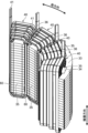
回転機としてのモータ10について、図1~5を参照して説明する。モータ10は、各種の製品に搭載される。例えば、モータ10は、電動車両の駆動源として利用される。電動車両の例としては、電気自動車、電動自転車、電動車椅子、電動カート及び電動配膳車が挙げられる。電気自動車は、ハイブリッド自動車を含む。モータ10は、ロータ20と、ステータ30とを備える(図1,2参照)。実施形態は、モータ10として内転型のブラシレスモータを例示する。<
The
ロータ20は、ロータコア21と、複数の永久磁石と、シャフト22とを備える。図1,2では、永久磁石の図示は省略されている。例えば、ロータコア21は、プレス機によって鋼板を打ち抜きつつ、打ち抜かれた鋼板を積層して形成される。鋼板としては、電磁鋼板が採用される。ロータコア21には、複数の永久磁石が設けられる。例えば、複数の永久磁石は、ロータコア21に形成された複数の空間にそれぞれ収納される。ロータ20がこのようなタイプのロータである場合、モータ10はIPM(Interior Permanent Magnet)モータと称される。複数の永久磁石は、ロータコア21の外周面に設けられてもよい。ロータ20がこのようなタイプのロータである場合、モータ10はSPM(Surface Permanent Magnet)モータと称される。
The
シャフト22は、ロータコア21の中心部に形成された貫通孔に固定される。シャフト22には、ロータコア21の両側に軸受が取り付けられる。軸受は、支持部に支持される。例えば、支持部は、ステータ30に設けられ、又はステータ30を支持する筐体に設けられる。図1,2では、軸受、支持部及び筐体の図示は省略されている。シャフト22は、ロータ20の回転軸となる。ロータ20は、シャフト22を中心として回転する。ロータ20は、公知のモータ(回転機)が備えるロータと同様である。従って、ロータ20に関するこの他の説明は省略する。
The
実施形態では、シャフト22(ロータ20の回転軸)を中心とする円周方向を「周方向」という。周方向は、回転方向及び反回転方向を含む。ロータ20は、回転方向に回転する。図1下段及び図2に示す次の矢印は回転方向を示す。前述の矢印は、図1下段ではロータ20の上側に示す円弧の矢印であり、図2ではロータ20の内部に示す円弧の矢印である。反回転方向は、回転方向とは反対である。シャフト22(ロータ20の回転軸)を中心とする放射方向を「径方向」という。
In the embodiment, the circumferential direction around the shaft 22 (rotation axis of the rotor 20) is referred to as the "circumferential direction." The circumferential direction includes a rotation direction and a counter-rotation direction. The
ステータ30は、ステータコア31と、複数のコイル40とを備える(図1,2参照)。更に、ステータ30は、絶縁部材60を備える(図3,4参照)。図1,2では、絶縁部材60の図示は省略されている。ステータコア31は、ヨーク32と、複数のティース35とを含む(図2参照)。内転型のモータ10で複数のティース35は、ヨーク32の内周で径方向の内側に突出する。ステータコア31には、ティース35と同数のスロット36が形成される。スロット36は、隣り合うティース35の間に形成された空間である。ステータ30でスロット数は、次の点を考慮して適宜決定される。前述の点の例としては、モータ10に対して要求される性能が挙げられる。
The
実施形態では、ステータコア31は、ヨーク32と複数のティース35とに分割させた態様を有する(図3参照)。ティース35の数は12本とする(図2参照)。この場合、スロット数は12個となる。ステータコア31では、12本のティース35は等角度間隔で設けられる。ヨーク32は、3個のヨーク片33に等分割させた態様を有する(図2~4参照)。1個のヨーク片33には、4本のティース35が設けられる(図4参照)。ステータコア31は、1個のヨーク片33に4本のティース35を装着し、3個のヨーク片33を環状に組み立てて形成される(図1~4参照)。ティース35の数、環状のヨーク32の分割数及び1個のヨーク片33に対するティース35の数は、実施形態とは異なる態様としてもよい。実施形態におけるこれらの数は例示である。
In the embodiment, the
ヨーク片33は、装着溝34を含む(図3,4参照)。装着溝34は、ティース35が設けられる径方向の内側に設けられる。ティース35の径方向の外側端は、装着溝34に嵌め込まれる。ヨーク片33には、装着溝34の内面に第一係合部を設けてもよく、ティース35には、径方向の外側端に第二係合部を設けてもよい。第二係合部は、第一係合部と係合する。即ち、ティース35は、径方向の外側端で装着溝34の内面と係合した状態でヨーク片33に装着される。実施形態では、第一係合部及び第二係合部の図示は省略されている。
The
例えば、ヨーク片33及びティース35は、プレス機によって鋼板を打ち抜きつつ、打ち抜かれた鋼板を積層して形成される。鋼板としては、電磁鋼板が採用される。実施形態では、ヨーク片33及びティース35で鋼板が積層される方向を「積層方向」という。ステータコア31が複数のヨーク片33及び複数のティース35で形成される場合(図1~4参照)、積層方向は、ステータコア31で鋼板が積層される方向ということもできる。積層方向は、ロータコア21で鋼板が積層される方向に一致する。ヨーク片33が装着溝34の内面に第一係合部を含み、ティース35が径方向の外側端に第二係合部を含むとする。この場合、ティース35のヨーク片33への装着は、積層方向の一方側から行ってもよい。
For example, the
コイル40は、平角導体によって形成される。複数のコイル40は、同じ平角導体によって形成され、同様のコイル構造を有する(図1,2,4参照)。複数のコイル40で採用されるコイル構造は、コイル40が千鳥構造(後述する図6,7及び図8上段参照)を採用する点を除き、上述した特許文献1で開示された巻線構造と同様である。千鳥構造については後述するコイル40のコイル構造の説明において後述する。実施形態では、千鳥構造を含むコイル40のコイル構造を単に「コイル構造」という。
コイル40は、絶縁部材60を介してティース35に設けられる(図3,4参照)。絶縁部材60は、電気絶縁性を有し、ティース35とコイル40とを電気的に絶縁する。即ち、ステータ30で複数のコイル40は、絶縁部材60によってステータコア31と電気的に絶縁される。実施形態では、絶縁部材60はスロット36内でティース35の周方向の両側面に設けられる。この場合、絶縁部材60は、スロット絶縁紙と称される。スロット絶縁紙は、公知のモータ(回転機)のステータでも採用される。この他、ステータ30では、公知のステータで採用されるインシュレータを含む絶縁構造を採用してもよい。インシュレータは、樹脂成形品であってもよい。ステータ30では、このような公知のステータと同様の絶縁部材を含む絶縁構造を採用することができる。ステータ30は、スロット絶縁紙及びインシュレータを共に含む絶縁構造を採用してもよい。従って、次の点に関するこの他の説明は省略する。前述の点は、絶縁部材60に関する。更に、前述の点は、絶縁部材60を用いたステータコア31とコイル40との電気的な絶縁構造に関する。
The
コイル40を形成する巻線方法の例としては、上述した特許文献1,3に開示された方法が挙げられる。この方法は、線材を螺旋状に変形させつつコイルを形成する。即ち、実施形態のコイル40は、特許文献1,3の装置と同様の巻線装置を用いつつ、これらに開示された方法に準じた巻線方法によって製造することができる。従って、コイル40の巻線方法に関する説明は適宜省略する。
Examples of the winding method for forming the
複数のコイル40は、U相、V相及びW相の何れかに分類される(図5参照)。実施形態では、U相のコイル40を「コイル40U」といい、V相のコイル40を「コイル40V」といい、W相のコイル40を「コイル40W」という。コイル40U,40V,40Wを区別しない場合又はこれらを総称する場合、「コイル40」という。コイル40の巻き初め側及び巻き終わり側では、コイル40を形成する平角導体がそれぞれ引き出される(図1~4参照)。実施形態では、この引き出された平角導体の部分を「引出線41U,41V,41W」という(図5参照)。引出線41Uは、コイル40Uを形成する平角導体によって形成される。引出線41Vは、コイル40Vを形成する平角導体によって形成される。引出線41Wは、コイル40Wを形成する平角導体によって形成される。引出線41U,41V,41Wを区別しない場合又はこれらを総称する場合、「引出線41」という。実施形態では、2本の引出線41のうち径方向の外側の引出線41を径方向の内側の引出線41より長くして示す。
The plurality of
複数のコイル40Uは、2本の引出線41Uのうちの所定の1本の引出線41Uの側で接続される(図5参照)。2本の引出線41Uのうちの残りの1本の引出線41Uは、U相の接続端子43Uに接続される。複数のコイル40Uは、U相のコイルユニット42Uを形成する。複数のコイル40Vは、2本の引出線41Vのうちの所定の1本の引出線41Vの側で接続される(図5参照)。2本の引出線41Vのうちの残りの1本の引出線41Vは、V相の接続端子43Vに接続される。複数のコイル40Vは、V相のコイルユニット42Vを形成する。複数のコイル40Wは、2本の引出線41Wのうちの所定の1本の引出線41Wの側で接続される(図5参照)。2本の引出線41Wのうちの残りの1本の引出線41Wは、W相の接続端子43Wに接続される。複数のコイル40Wは、W相のコイルユニット42Wを形成する。
The plurality of
実施形態では、コイルユニット42U,42V,42Wを区別しない場合又はこれらを総称する場合、「コイルユニット42」という。接続端子43U,43V,43Wを区別しない場合又はこれらを総称する場合、「接続端子43」という。引出線41と接続端子43とを接続する接続方法の例としては、かしめ及び溶接が挙げられる。
In the embodiment, when the
引出線41と接続端子43との接続は、第一連結導体44を介して行ってもよい(図5参照)。第一連結導体44は、引出線41とは別体の平角導体製としてもよい。第一連結導体44は、引出線41及び接続端子43に接続され、これらを電気的に接続する。次の第一接続方法の例としては、溶接が挙げられる。第一接続方法は、引出線41と第一連結導体44とを接続する。次の第二接続方法は、引出線41と接続端子43との接続の場合と同様である。第二接続方法は、接続端子43と第一連結導体44とを接続する。第一連結導体44は、コイル40と同じ平角導体製とすることが好ましい。但し、引出線41と接続端子43との接続は、次の態様としてもよい。前述の態様では、複数の引出線41Uは、それぞれ次の長さで引き出され、直接、接続端子43Uに接続される。前述の態様では、複数の引出線41Vは、それぞれ次の長さで引き出され、直接、接続端子43Vに接続される。前述の態様では、複数の引出線41Wは、それぞれ次の長さで引き出され、直接、接続端子43Wに接続される。前述の長さは、引出線41と同相の接続端子43に至る経路を考慮して決定される。
The connection between the
ステータ30では、1相分のコイルユニット42を形成する4個のコイル40は並列接続され、且つコイルユニット42U,42V,42Wはスター結線される(図5参照)。図5の中心に示す黒丸は、中性点を示す。同相の4個のコイル40の並列接続及びコイルユニット42U,42V,42Wのスター結線は、引出線41とは別体の平角導体製の第二連結導体45を介して行ってもよい(図5参照)。第二連結導体45は、同相の4個のコイル40の引出線41に接続され、コイルユニット42U,42V,42Wを電気的に接続する。次の第三接続方法は、引出線41と第一連結導体44との接続の場合と同様である。第三接続方法は、引出線41と第二連結導体45とを接続する。
In the
但し、コイルユニット42U,42V,42Wの結線態様は、スター結線でなくてもよい。スター結線とは異なる結線態様の例としては、デルタ結線が挙げられる。コイルユニット42U,42V,42Wの結線態様は、諸条件を考慮して適宜決定される。図1,2,4では、第一連結導体44及び第二連結導体45の図示は省略されている。
However, the connection mode of the
<コイル構造>
コイル構造について図1~4,6を参照して説明する。コイル40は、複数のコイル層50を含む。実施形態では、コイル40は、6個のコイル層50を含む(図3,6参照)。コイル40に設けるコイル層50の数は、2個以上5個以下としてもよく、又は7個以上としてもよい。コイル40のコイル層50の数は、諸条件を考慮して適宜決定される。実施形態では、6個のコイル層50を「コイル層51,52,53,54,55,56」という。コイル層51,52,53,54,55,56を区別しない場合又はこれらを総称する場合、「コイル層50」という。<Coil structure>
The coil structure will be explained with reference to FIGS. 1 to 4 and 6.
コイル層50は、平角導体を渦巻き状に巻回させた構造を有する(図3上段参照)。「渦巻き」は、「螺旋状に巻いた平面曲線の形」(広辞苑第七版 岩波書店)を意味する。複数のコイル層50の一部又は全部で平角導体のターン数は、異ならせてもよく(図1~4参照)、又は同じとしてもよい(図6及び後述する図7上段参照)。複数のコイル層50で平角導体のターン数は、諸条件を考慮して適宜決定される。
The
実施形態では、コイル層51,52,53,54,55,56で平角導体が重なり合う放射状の方向を「第一方向」といい、第一方向に直交する方向を「第二方向」という。第二方向の一方側を「第一側」といい、第二方向の他方側を「第二側」という。第二方向は、モータ10(回転機)の状態で径方向に一致してもよい。モータ10では、第二方向は径方向に一致する。モータ10(回転機)の状態は、ステータ30の状態を含む。更に、モータ10(回転機)の状態及びステータ30の状態は、コイル40がティース35に設けられた状態を含む。第二方向の第一側を径方向の内側とした場合、第二方向の第二側は径方向の外側となる(図3参照)。これとは異なり、第二方向の第一側を径方向の外側とした場合、第二方向の第二側は径方向の内側となる。
In the embodiment, the radial direction in which the rectangular conductors overlap in the coil layers 51, 52, 53, 54, 55, and 56 is referred to as a "first direction", and the direction orthogonal to the first direction is referred to as a "second direction". One side in the second direction is referred to as the "first side", and the other side in the second direction is referred to as the "second side". The second direction may coincide with the radial direction of the motor 10 (rotating machine). In the
実施形態では、コイル層51,52,53,54,55,56は、第二方向の第一側から第二側にこの順で設けられる(図3上段及び図6参照)。コイル層51,52,53,54,55,56の第二方向の第一側の側面を「第一側面」といい、コイル層51,52,53,54,55,56の第二方向の第二側の側面を「第二側面」という。コイル層50の第一側面は、コイル層51,52,53,54,55,56の一部又は全部の第一側面を意味する。コイル層50の第二側面は、コイル層51,52,53,54,55,56の一部又は全部の第二側面を意味する。
In the embodiment, the coil layers 51, 52, 53, 54, 55, and 56 are provided in this order from the first side to the second side in the second direction (see the upper part of FIG. 3 and FIG. 6). The first side surface of the coil layers 51, 52, 53, 54, 55, 56 in the second direction is referred to as the "first side surface"; The second side is called the "second side." The first side of the
実施形態では、放射状の第一方向として、次の「第一軸方向」及び「第二軸方向」を定義する。第二軸方向は、第一軸方向に直交する。モータ10を基準とした場合、第一軸方向は積層方向に一致することとし、第二軸方向は積層方向及び径方向の両方向に直交することとする。
In the embodiment, the following "first axial direction" and "second axial direction" are defined as the radial first direction. The second axial direction is perpendicular to the first axial direction. When the
コイル層52は、コイル40の内周側で平角導体によってコイル層51と繋がる。コイル層52は、第一側面でコイル層51の第二側面と接する(図3上段及び図6参照)。コイル層53は、コイル40の外周側で平角導体によってコイル層52と繋がる。コイル層53は、第一側面でコイル層52の第二側面と接する(図3上段及び図6参照)。コイル層54は、コイル40の内周側で平角導体によってコイル層53と繋がる。コイル層54は、第一側面でコイル層53の第二側面と接する(図3上段及び図6参照)。コイル層55は、コイル40の外周側で平角導体によってコイル層54と繋がる。コイル層55は、第一側面でコイル層54の第二側面と接する(図3上段及び図6参照)。コイル層56は、コイル40の内周側で平角導体によってコイル層55と繋がる。コイル層56は、第一側面でコイル層55の第二側面と接する(図3上段及び図6参照)。実施形態では、2個のコイル層50を繋ぐ平角導体の図示は次の一部を除き省略されている。前述の一部は、コイル層51,52を繋ぐ平角導体と、コイル層53,54を繋ぐ平角導体とである(図3上段の「コイル40の内周側」参照)。コイル40に対する2個のコイル層50を繋ぐ平角導体の配置は、諸条件を考慮して適宜決定される。
The
<千鳥構造>
コイル構造が採用する千鳥構造について、図3,6及び図8上段を参照して説明する。但し、この説明は、第二方向に接するコイル層51,52を対象とする。コイル40では、コイル層52,53、コイル層53,54、コイル層54,55及びコイル層55,56は、コイル層51,52と同様、第二方向に接する。説明は省略するが、コイル層52,53、コイル層53,54、コイル層54,55及びコイル層55,56でも、コイル層51,52と同様の構造が実現される。<staggered structure>
The staggered structure adopted by the coil structure will be described with reference to FIGS. 3 and 6 and the upper part of FIG. 8. However, this description focuses on the coil layers 51 and 52 that are in contact with each other in the second direction. In the
この説明では、コイル層52の第一側面とコイル層51の第二側面とが接した状態を「接触状態」という。コイル層51の部分を「第一部分A」及び「第二部分B」といい、コイル層52の部分を「第三部分C」及び「第四部分D」という(図6,7及び図8上段参照)。第一部分Aはコイル層51の2層目を形成し、第二部分Bはコイル層51の3層目を形成する。第三部分Cはコイル層52の2層目を形成し、第四部分Dはコイル層52の3層目を形成する。但し、コイル層51,52において、第一部分A、第二部分B、第三部分C及び第四部分Dは説明用の例示である。第二方向において隣り合う2個のコイル層50において、第一部分A、第二部分B、第三部分C及び第四部分Dに相当する4個の部分は、以下に説明する条件を満足する範囲で任意に設定することができる。
In this description, the state in which the first side surface of the
第二部分Bは、第一部分Aと連続し且つ内周面で第一部分Aの外周面と接する(図6,7及び図8上段参照)。換言すれば、第一部分Aは、第二部分Bと連続し且つ外周面で第二部分Bの内周面と接する。第四部分Dは、第三部分Cと連続し且つ内周面で第三部分Cの外周面と接する(図6,7及び図8上段参照)。換言すれば、第三部分Cは、第四部分Dと連続し且つ外周面で第四部分Dの内周面と接する。 The second portion B is continuous with the first portion A and contacts the outer peripheral surface of the first portion A at its inner peripheral surface (see FIGS. 6, 7 and the upper part of FIG. 8). In other words, the first portion A is continuous with the second portion B and contacts the inner peripheral surface of the second portion B with its outer peripheral surface. The fourth portion D is continuous with the third portion C and contacts the outer peripheral surface of the third portion C at its inner peripheral surface (see FIGS. 6, 7 and the upper part of FIG. 8). In other words, the third portion C is continuous with the fourth portion D and contacts the inner peripheral surface of the fourth portion D with its outer peripheral surface.
第三部分Cは、接触状態で、第一部分A及び第二部分Bと第二方向に隣り合う(図6,7及び図8上段参照)。第三部分Cの外周面は、接触状態で、第一部分Aの外周面より第一方向の外周側で且つ第二部分Bの外周面より第一方向の内周側に配置される。即ち、第三部分Cの外周面は、接触状態で、第一部分Aの外周面より第一軸方向の外周側で且つ第二部分Bの外周面より第一軸方向の内周側に配置される(図6参照)。更に、第三部分Cの外周面は、接触状態で、第一部分Aの外周面より第二軸方向の外周側で且つ第二部分Bの外周面より第二軸方向の内周側に配置される(図7参照)。 The third portion C is in contact with and adjoins the first portion A and the second portion B in the second direction (see FIGS. 6, 7 and the upper part of FIG. 8). The outer circumferential surface of the third portion C is arranged in contact with the outer circumferential surface of the first portion A on the outer circumferential side in the first direction and on the inner circumferential side in the first direction than the outer circumferential surface of the second portion B. That is, the outer circumferential surface of the third portion C is disposed in contact with the outer circumferential surface of the first portion A on the outer circumferential side in the first axial direction and on the inner circumferential side in the first axial direction than the outer circumferential surface of the second portion B. (See Figure 6). Furthermore, the outer circumferential surface of the third portion C is disposed in a contact state on the outer circumferential side of the outer circumferential surface of the first portion A in the second axial direction and on the inner circumferential side of the second axial direction than the outer circumferential surface of the second portion B. (See Figure 7).
第四部分Dは、接触状態で、第一部分Aと第二方向に隣り合わずに第二部分Bと第二方向に隣り合う(図6,7及び図8上段参照)。第四部分Dの外周面は、接触状態で、第二部分Bの外周面より第一方向の外周側に配置される。即ち、第四部分Dの外周面は、接触状態で、第二部分Bの外周面より第一軸方向の外周側に配置される(図6参照)。更に、第四部分Dの外周面は、接触状態で、第二部分Bの外周面より第二軸方向の外周側に配置される(図7参照)。 The fourth portion D is in contact with the second portion B in the second direction without being adjacent to the first portion A in the second direction (see FIGS. 6, 7 and the upper part of FIG. 8). The outer circumferential surface of the fourth portion D is arranged on the outer circumferential side in the first direction than the outer circumferential surface of the second portion B in a contacting state. That is, the outer circumferential surface of the fourth portion D is disposed on the outer circumferential side in the first axial direction than the outer circumferential surface of the second portion B in a contacting state (see FIG. 6). Furthermore, the outer circumferential surface of the fourth portion D is arranged on the outer circumferential side in the second axial direction than the outer circumferential surface of the second portion B in a contacting state (see FIG. 7).
即ち、コイル40では、次の第一コイル層の平角導体は、次の第二コイル層の平角導体と第一方向にずれて配置される(千鳥構造 図6,7及び図8上段参照)。コイル40の第一コイル層及び第二コイル層は、コイル層51,52,53,54,55,56のうち、第二方向に隣り合う2個のコイル層50である。コイル40では、第一コイル層の平角導体と第二コイル層の平角導体との第一方向の位置ずれは、第一軸方向の位置ずれと、第二軸方向の位置ずれとを含む(図6,7参照)。
That is, in the
コイル40が特許文献1,3に開示された巻線方法に準じて形成されるとする。平角導体を巻回し、第一部分A、第二部分B、第三部分C及び第四部分Dの第一軸部分E1、角部及び第二軸部分E2を順次形成する場合、平角導体は所定の送り量だけ送られる。第一軸部分E1は、第一部分A、第二部分B、第三部分C及び第四部分Dで第一軸方向に沿う。第二軸部分E2は、第一部分A、第二部分B、第三部分C及び第四部分Dで第二軸方向に沿う。角部は、第一軸部分E1と第二軸部分E2とを繋ぐ。巻線方法での平角導体の送り量は、諸条件を考慮して適宜決定される。例えば、第一部分A、第二部分B、第三部分C及び第四部分Dで第一軸部分E1及び第二軸部分E2を形成する場合、平角導体の送り量の関係は「第一部分A=第二部分B,第三部分C=第四部分D,第一部分A<第三部分C」であってもよい。例えば、第一部分A、第二部分B、第三部分C及び第四部分Dで角部を形成する場合、平角導体の送り量の関係は「第一部分A<第三部分C<第二部分B<第四部分D」であってもよい。
It is assumed that the
<実施形態の効果>
実施形態によれば、次のような効果を得ることができる。<Effects of embodiment>
According to the embodiment, the following effects can be obtained.
(1)コイル40は、複数のコイル層50を含む(図3上段及び図6参照)。コイル層50は、平角導体を渦巻き状に巻回させて形成される。複数のコイル層50は、平角導体によって繋がる。コイル層50を繋ぐ平角導体は、コイル層50と同じ平角導体であり、コイル層50を形成する平角導体と連続する。例えば、複数のコイル層50のうちのコイル層52は、第二方向の第一側の第一側面で複数のコイル層50のうちのコイル層51の第二方向の第二側の第二側面と接する。コイル層51は、第一部分Aと、第二部分Bとを含む(図6,7及び図8上段参照)。第二部分Bは、第一部分Aと連続し且つ内周面で第一部分Aの外周面と接する。コイル層52は、第三部分Cと、第四部分Dとを含む(図6,7及び図8上段参照)。第四部分Dは、第三部分Cと連続し且つ内周面で第三部分Cの外周面と接する。
(1) The
第三部分Cは、接触状態で、第一部分A及び第二部分Bと第二方向に隣り合う(図6,7及び図8上段参照)。第四部分Dは、接触状態で、第一部分Aと第二方向に隣り合わずに第二部分Bと第二方向に隣り合う(図6,7及び図8上段参照)。第三部分Cの外周面は、接触状態で、第一部分Aの外周面より第一方向の外周側で且つ第二部分Bの外周面より第一方向の内周側に配置される(図6,7及び図8上段参照)。第四部分Dの外周面は、接触状態で、第二部分Bの外周面より第一方向の外周側に配置される(図6,7及び図8上段参照)。 The third portion C is in contact with and adjoins the first portion A and the second portion B in the second direction (see FIGS. 6, 7 and the upper part of FIG. 8). The fourth portion D is in contact with the second portion B in the second direction without being adjacent to the first portion A in the second direction (see FIGS. 6, 7 and the upper part of FIG. 8). The outer circumferential surface of the third portion C is arranged in contact with the outer circumferential surface of the first portion A on the outer circumferential side in the first direction and on the inner circumferential side in the first direction than the outer circumferential surface of the second portion B (Fig. 6 , 7 and the upper part of FIG. 8). The outer circumferential surface of the fourth portion D is arranged on the outer circumferential side in the first direction than the outer circumferential surface of the second portion B in a contacting state (see FIGS. 6, 7 and the upper part of FIG. 8).
第三部分Cの外周面は、接触状態で、第一部分Aの外周面より第一軸方向の外周側で且つ第二部分Bの外周面より第一軸方向の内周側に配置される(図6参照)。第四部分Dの外周面は、接触状態で、第二部分Bの外周面より第一軸方向の外周側に配置される(図6参照)。第三部分Cの外周面は、接触状態で、第一部分Aの外周面より第二軸方向の外周側で且つ第二部分Bの外周面より第二軸方向の内周側に配置される(図7参照)。第四部分Dの外周面は、接触状態で、第二部分Bの外周面より第二軸方向の外周側に配置される(図7参照)。第一軸方向及び第二軸方向は、放射状の第一方向に含まれる。即ち、第一軸方向及び第二軸方向は、第一方向を含む仮想平面内に含まれる。更に、第二軸方向は、第一軸方向と直交する。 The outer circumferential surface of the third portion C is disposed in contact with the outer circumferential surface of the first portion A on the outer circumferential side in the first axial direction and on the inner circumferential side in the first axial direction than the outer circumferential surface of the second portion B. (See Figure 6). The outer circumferential surface of the fourth portion D is arranged on the outer circumferential side in the first axial direction than the outer circumferential surface of the second portion B in a contacting state (see FIG. 6). The outer circumferential surface of the third portion C is arranged in contact with the outer circumferential surface of the first portion A on the outer circumferential side in the second axial direction and on the inner circumferential side in the second axial direction than the outer circumferential surface of the second portion B ( (See Figure 7). The outer circumferential surface of the fourth portion D is arranged on the outer circumferential side in the second axial direction than the outer circumferential surface of the second portion B in a contacting state (see FIG. 7). The first axial direction and the second axial direction are included in the radial first direction. That is, the first axial direction and the second axial direction are included within a virtual plane that includes the first direction. Furthermore, the second axial direction is perpendicular to the first axial direction.
平角導体をティース35の外周形状に対応させて渦巻き状に巻回させた場合、上述した通り、平角導体には第一軸部分E1と第二軸部分E2とを繋ぐ部分に角部が形成される(図6参照)。発明者は、平角導体は角部の外周側では長さ方向に伸張し且つ角部の内周側では長さ方向に収縮することを知っている。発明者は、このような変形が生じることで角部を形成する平角導体は長方形状の断面形状が次の態様へと変形した状態になることを知っている(図8参照)。前述の態様は、内周側の辺が外周側の辺より長い台形状である。
When the rectangular conductor is spirally wound in accordance with the outer peripheral shape of the
コイルがコイル70であるとする(図8下段参照)。コイル70は、実施形態のコイル40に対する比較例である。コイル70は、連続する1本の平角導体をそれぞれ巻回させて形成されたコイル層71,72,73,74,75,76を含む。コイル層71,72,73,74,75,76は、前述した1本の平角導体によって繋がる。コイル層71,72,73,74,75,76は、第二方向の第一側から第二側にこの順で設けられる(図8下段参照)。コイル層72は、第一側面でコイル層71の第二側面と接する。コイル層73は、第一側面でコイル層72の第二側面と接する。コイル層74は、第一側面でコイル層73の第二側面と接する。コイル層75は、第一側面でコイル層74の第二側面と接する。コイル層76は、第一側面でコイル層75の第二側面と接する。コイル層71,72,73,74,75,76の第一側面は、コイル層50の第一側面と同様、コイル層71,72,73,74,75,76の第二方向の第一側を形成する。コイル層71,72,73,74,75,76の第二側面は、コイル層50の第二側面と同様、コイル層71,72,73,74,75,76の第二方向の第二側を形成する。コイル層71,72,73,74,75,76では、平角導体の第一方向の位置が同じとなる。この場合、次の2個の部分は、内周側で第二方向に接し、外周側では第二方向に接しない。前述の2個の部分は、第三コイル層の角部を形成し且つ断面形状が台形状に変形した平角導体の部分と、第四コイル層の角部を形成し且つ断面形状が台形状に変形した平角導体の部分とである。第三コイル層及び第四コイル層は、コイル層71,72,73,74,75,76のうち、第二方向に隣り合う2個のコイル層である。即ち、これら2個の部分の外周側には隙間Sが生じる(図8下段参照)。
Assume that the coil is a coil 70 (see the lower part of FIG. 8).
コイル40によれば、上述した比較例のコイル70の角部に生じるような隙間Sの発生を抑制することができる(図8上段参照)。即ち、コイル40では、平角導体の断面形状が台形状に変形することを利用して第二方向に隣り合うコイル層50同士を第二方向に密接させることができる。コイル40を第二方向に小型化することができる(図8の「ΔL」参照)。第二方向の寸法が大きな平角導体を採用することが可能となる。
According to the
(2)モータ10は、ロータ20と、ステータ30とを備える(図1,2参照)。ステータ30は、コイル40と、ステータコア31とを備える。ステータコア31は、鋼板を積層して形成される。ステータコア31は、ヨーク32と、ティース35とを含む。コイル40は、ティース35に設けられる。
(2) The
小型化されたモータ10とすることができる。モータ10では、占積率を向上させることが可能となる場合がある。占積率の向上によってモータ10の効率を向上させることができる。
The
<変形例>
実施形態は、次のようにすることもできる。以下に示す変形例のうちの幾つかの構成は、適宜組み合わせて採用することもできる。以下では、上記とは異なる点を説明することとし、同様の点についての説明は適宜省略する。<Modified example>
Embodiments can also be as follows. Some of the configurations of the modified examples shown below can also be employed in combination as appropriate. In the following, points different from the above will be explained, and explanations of similar points will be omitted as appropriate.
(1)回転機として内転型のモータ10を例示した。モータ10は、ステータ30にコイル40を備える(図1,2参照)。コイル40のコイル構造は、千鳥構造を含む(図6,7及び図8上段参照)。コイル40が採用するこのようなコイル構造は、外転型のモータのステータのコイルに採用することもできる。この他、コイル40のコイル構造は、発電機のステータのコイル及び変圧器のコイルに採用することもできる。
(1) An internal
(2)モータ10を基準とした場合、第一軸方向は積層方向に一致し、第二軸方向は積層方向及び径方向の両方向に直交する。第一軸方向及び第二軸方向の設定は、上記とは反対としてもよい。即ち、モータ10を基準とした場合、第一軸方向は積層方向及び径方向の両方向に直交してもよく、第二軸方向は積層方向に一致してもよい。
(2) When the
(3)ステータ30では、1相分のコイルユニット42を形成する複数のコイル40は並列接続される(図5参照)。1相分のコイルユニットで複数のコイルは、直列接続されてもよい。この場合、1相分のコイルユニットは、特許文献1,2で開示された技術を採用することで、連続する1本の平角導体によって形成することができる。1相分のコイルユニットは、特許文献1~3に開示された巻線装置と同様の巻線装置を用いてこれらに開示された巻線方法に準じた方法によって製造することができる。但し、コイルは、コイル40と同様、千鳥構造を含むコイル構造となるように巻線される。上述したステータ30と同様、ステータコアが12本のティースを含むとする。直列に設けられる複数のコイルを接続する平角導体を「渡り線」という。1相分のコイルユニットは、両端に引出線が1本ずつ設けられ、3本の渡り線によって接続された4個のコイルを含む。即ち、1相分のコイルユニットで4個のコイル、3本の渡り線及び2本の引出線は、引出線、コイル、渡り線、コイル、渡り線、コイル、渡り線、コイル及び引出線の順で連なる。U相、V相及びW相のコイルユニットの結線態様がスター結線であるとする。この場合、U相、V相及びW相のコイルユニットで、2本の引出線のうちの一方の引出線は、他の相のコイルユニットの一方の引出線と接続され、2本の引出線のうちの残りの1本の引出線は、対応する相の接続端子に接続される。
(3) In the
10 モータ、 20 ロータ、 21 ロータコア
22 シャフト、 30 ステータ、 31 ステータコア
32 ヨーク、 33 ヨーク片、 34 装着溝、 35 ティース
36 スロット、 40,40U,40V,40W コイル
41,41U,41V,41W 引出線
42,42U,42V,42W コイルユニット
43,43U,43V,43W 接続端子
44 第一連結導体、 45 第二連結導体
50,51,52,53,54,55,56 コイル層
60 絶縁部材、 70 コイル
71,72,73,74,75,76 コイル層
A 第一部分、 B 第二部分、 C 第三部分、 D 第四部分
E1 第一軸部分、 E2 第二軸部分、 S 隙間10 motor, 20 rotor, 21
Claims (4)
前記平角導体によって前記第一コイル層と繋がり、前記平角導体を渦巻き状に巻回させた第二コイル層と、を含み、
前記第二コイル層は、前記第二コイル層の前記第一コイル層及び前記第二コイル層で前記平角導体が重なり合う放射状の第一方向に直交する第二方向の第一側の第一側面で前記第一コイル層の前記第二方向の第二側の第二側面と接し、
前記第一コイル層は、
第一部分と、
前記第一部分と連続し且つ内周面で前記第一部分の外周面と接する第二部分と、を含み、
前記第一部分の前記第一方向としての第一軸方向に沿った第一軸部分と前記第一部分の前記第一軸方向に直交する前記第一方向としての第二軸方向に沿った第二軸部分とを繋ぐ前記第一部分の角部は、前記第一方向の内周側の辺が前記第一方向の外周側の辺より長い台形状の断面形状を有し、
前記第二部分の前記第一軸方向に沿った第一軸部分と前記第二部分の前記第二軸方向に沿った第二軸部分とを繋ぐ前記第二部分の角部は、前記第一方向の内周側の辺が前記第一方向の外周側の辺より長い台形状の断面形状を有し、
前記第二コイル層は、
第三部分と、
前記第三部分と連続し且つ内周面で前記第三部分の外周面と接する第四部分と、を含み、
前記第三部分の前記第一軸方向に沿った第一軸部分と前記第三部分の前記第二軸方向に沿った第二軸部分とを繋ぐ前記第三部分の角部は、前記第一方向の内周側の辺が前記第一方向の外周側の辺より長い台形状の断面形状を有し、
前記第四部分の前記第一軸方向に沿った第一軸部分と前記第四部分の前記第二軸方向に沿った第二軸部分とを繋ぐ前記第四部分の角部は、前記第一方向の内周側の辺が前記第一方向の外周側の辺より長い台形状の断面形状を有し、
前記第三部分は、前記第一側面と前記第二側面とが接した接触状態で、前記第一部分及び前記第二部分と前記第二方向に隣り合い、
前記第四部分は、前記接触状態で、前記第一部分と前記第二方向に隣り合わずに前記第二部分と前記第二方向に隣り合い、
前記第三部分の外周面は、前記接触状態で、前記第一部分の外周面より前記第一方向の外周側で且つ前記第二部分の外周面より前記第一方向の内周側に配置され、
前記第四部分の外周面は、前記接触状態で、前記第二部分の外周面より前記第一方向の外周側に配置され、
前記第二部分の角部の前記第一方向の内周側は、前記第四部分の角部の内周面と、前記第一方向の外周側から内周側に向かって前記第二方向の第二側から第一側に傾斜した前記第三部分の角部の前記第二方向の第一側の傾斜面と、によって囲まれた領域に配置され、
前記第三部分の角部の前記第一方向の内周側は、前記第二部分の角部の内周面と、前記第一方向の外周側から内周側に向かって前記第二方向の第一側から第二側に傾斜した前記第一部分の角部の前記第二方向の第二側の傾斜面と、によって囲まれた領域に配置される、コイル。 a first coil layer in which a rectangular conductor is spirally wound;
a second coil layer connected to the first coil layer by the rectangular conductor and having the rectangular conductor spirally wound;
The second coil layer is a first side surface of the second coil layer on a first side in a second direction perpendicular to a radial first direction in which the rectangular conductor overlaps in the first coil layer and the second coil layer. in contact with a second side surface of the second side of the first coil layer in the second direction;
The first coil layer is
The first part and
a second part that is continuous with the first part and whose inner peripheral surface contacts the outer peripheral surface of the first part,
a first axial portion of the first portion along a first axial direction as the first direction; and a second axis of the first portion along a second axial direction as the first direction orthogonal to the first axial direction. The corner of the first part that connects the first part has a trapezoidal cross-sectional shape in which the inner peripheral side in the first direction is longer than the outer peripheral side in the first direction,
A corner of the second portion that connects a first shaft portion of the second portion along the first axis direction and a second shaft portion of the second portion along the second axis direction is having a trapezoidal cross-sectional shape in which the inner circumferential side in the direction is longer than the outer circumferential side in the first direction;
The second coil layer is
a third part;
a fourth part that is continuous with the third part and whose inner peripheral surface contacts the outer peripheral surface of the third part,
A corner of the third portion connecting a first axis portion of the third portion along the first axis direction and a second axis portion of the third portion along the second axis direction is having a trapezoidal cross-sectional shape in which the inner circumferential side in the direction is longer than the outer circumferential side in the first direction;
A corner of the fourth portion connecting a first axis portion of the fourth portion along the first axis direction and a second axis portion of the fourth portion along the second axis direction is having a trapezoidal cross-sectional shape in which the inner circumferential side in the direction is longer than the outer circumferential side in the first direction;
The third portion is adjacent to the first portion and the second portion in the second direction with the first side surface and the second side surface in contact with each other,
The fourth portion is adjacent to the second portion in the second direction without being adjacent to the first portion in the second direction in the contact state,
The outer circumferential surface of the third portion is arranged in the contact state on the outer circumferential side in the first direction than the outer circumferential surface of the first portion and on the inner circumferential side in the first direction than the outer circumferential surface of the second portion,
The outer circumferential surface of the fourth portion is arranged on the outer circumferential side in the first direction than the outer circumferential surface of the second portion in the contact state ,
The inner circumferential side of the corner of the second portion in the first direction is connected to the inner circumferential surface of the corner of the fourth portion from the outer circumferential side in the first direction to the inner circumferential side in the second direction. and an inclined surface on the first side in the second direction of the corner of the third portion inclined from the second side to the first side,
The inner circumferential side of the corner of the third portion in the first direction is connected to the inner circumferential surface of the corner of the second portion in the second direction from the outer circumferential side to the inner circumferential side in the first direction. and an inclined surface on a second side in the second direction of a corner of the first portion that is inclined from the first side to the second side.
前記第四部分の外周面は、前記接触状態で、前記第二部分の外周面より前記第一軸方向の外周側に配置される、請求項1に記載のコイル。 In the contact state, the outer circumferential surface of the third portion is arranged on the outer circumferential side in the first axial direction than the outer circumferential surface of the first portion and on the inner circumferential side in the first axial direction than the outer circumferential surface of the second portion. is,
The coil according to claim 1, wherein the outer circumferential surface of the fourth portion is arranged on the outer circumferential side in the first axial direction than the outer circumferential surface of the second portion in the contact state.
前記第四部分の外周面は、前記接触状態で、前記第二部分の外周面より前記第二軸方向の外周側に配置される、請求項2に記載のコイル。 In the contact state, the outer circumferential surface of the third portion is on the outer circumferential side in the second axial direction than the outer circumferential surface of the first portion and on the inner circumferential side in the second axial direction than the outer circumferential surface of the second portion. placed,
The coil according to claim 2, wherein the outer circumferential surface of the fourth portion is arranged on the outer circumferential side in the second axial direction than the outer circumferential surface of the second portion in the contact state.
ステータと、を備え、
前記ステータは、
請求項1から請求項3の何れか1項に記載のコイルと、
鋼板を積層して形成され、ヨークと、前記ヨークから前記ロータの側に向かって前記第二方向に突出するティースと、を含むステータコアと、を備え、
前記コイルは、前記ティースに設けられる、回転機。 rotor and
comprising a stator;
The stator is
The coil according to any one of claims 1 to 3,
a stator core formed by laminating steel plates and including a yoke and teeth protruding from the yoke toward the rotor side in the second direction;
The coil is a rotating machine provided on the teeth.
Applications Claiming Priority (3)
| Application Number | Priority Date | Filing Date | Title |
|---|---|---|---|
| JP2021081283 | 2021-05-12 | ||
| JP2021081283 | 2021-05-12 | ||
| PCT/JP2022/016022 WO2022239561A1 (en) | 2021-05-12 | 2022-03-30 | Coil and rotary machine |
Publications (2)
| Publication Number | Publication Date |
|---|---|
| JPWO2022239561A1 JPWO2022239561A1 (en) | 2022-11-17 |
| JP7380997B2 true JP7380997B2 (en) | 2023-11-15 |
Family
ID=84028251
Family Applications (1)
| Application Number | Title | Priority Date | Filing Date |
|---|---|---|---|
| JP2023514847A Active JP7380997B2 (en) | 2021-05-12 | 2022-03-30 | Coil and rotating machine |
Country Status (4)
| Country | Link |
|---|---|
| US (1) | US12567777B2 (en) |
| EP (1) | EP4340183A4 (en) |
| JP (1) | JP7380997B2 (en) |
| WO (1) | WO2022239561A1 (en) |
Families Citing this family (1)
| Publication number | Priority date | Publication date | Assignee | Title |
|---|---|---|---|---|
| WO2021230084A1 (en) * | 2020-05-14 | 2021-11-18 | 東芝産業機器システム株式会社 | Insulator, stator, and rotating electric machine |
Citations (2)
| Publication number | Priority date | Publication date | Assignee | Title |
|---|---|---|---|---|
| JP2005304244A (en) | 2004-04-15 | 2005-10-27 | Toyota Motor Corp | Coil for rotating electrical machine, rotating electrical machine, and method for manufacturing coil |
| WO2014068695A1 (en) | 2012-10-31 | 2014-05-08 | 三菱電機株式会社 | Coil for rotary electric machine and rotary electric machine |
Family Cites Families (6)
| Publication number | Priority date | Publication date | Assignee | Title |
|---|---|---|---|---|
| JP5386265B2 (en) * | 2009-08-05 | 2014-01-15 | 日立オートモティブシステムズ株式会社 | Rotating electric machine and vehicle |
| JP5555933B2 (en) | 2012-11-02 | 2014-07-23 | 福井県 | Winding manufacturing method and manufacturing apparatus |
| JP5499349B2 (en) | 2012-11-02 | 2014-05-21 | 福井県 | Winding structure and electrical equipment using the same |
| JP6276041B2 (en) * | 2014-01-21 | 2018-02-07 | トヨタ自動車株式会社 | Rotating electrical machine stator |
| JP5768305B1 (en) | 2014-09-19 | 2015-08-26 | 福井県 | Stator manufacturing method and apparatus |
| FI20186094A1 (en) | 2018-12-17 | 2020-06-18 | Lappeenrannan Teknillinen Yliopisto | A tangle for the winding of an electric machine |
-
2022
- 2022-03-30 EP EP22807265.8A patent/EP4340183A4/en active Pending
- 2022-03-30 JP JP2023514847A patent/JP7380997B2/en active Active
- 2022-03-30 WO PCT/JP2022/016022 patent/WO2022239561A1/en not_active Ceased
- 2022-03-30 US US18/290,060 patent/US12567777B2/en active Active
Patent Citations (2)
| Publication number | Priority date | Publication date | Assignee | Title |
|---|---|---|---|---|
| JP2005304244A (en) | 2004-04-15 | 2005-10-27 | Toyota Motor Corp | Coil for rotating electrical machine, rotating electrical machine, and method for manufacturing coil |
| WO2014068695A1 (en) | 2012-10-31 | 2014-05-08 | 三菱電機株式会社 | Coil for rotary electric machine and rotary electric machine |
Also Published As
| Publication number | Publication date |
|---|---|
| US12567777B2 (en) | 2026-03-03 |
| US20240243633A1 (en) | 2024-07-18 |
| JPWO2022239561A1 (en) | 2022-11-17 |
| EP4340183A1 (en) | 2024-03-20 |
| EP4340183A4 (en) | 2025-05-07 |
| WO2022239561A1 (en) | 2022-11-17 |
Similar Documents
| Publication | Publication Date | Title |
|---|---|---|
| USRE46265E1 (en) | Rotating electric apparatus and method for connecting stator coils thereof | |
| CN105210267B (en) | Electric rotating machine and its manufacturing method | |
| CN106464059B (en) | The manufacturing method of stator coil, stator, calutron and stator coil | |
| US8779643B2 (en) | Stator for electric rotating machine and method of manufacturing same | |
| CN104584391B (en) | Rotary electric machine and manufacturing method therefor | |
| JP5472057B2 (en) | Stator winding winding method, stator winding winding device and stator winding manufacturing apparatus | |
| US8203247B2 (en) | Stator for electric rotating machine | |
| KR20120041127A (en) | Stator, brushless motor, and manufacturing method of the same | |
| US20100148621A1 (en) | Stator for electric rotating machine | |
| JP6165260B2 (en) | Rotating electric machine | |
| CN110445268B (en) | Stator for rotating electric machine | |
| JP2016152752A (en) | Stator for rotary electric machine | |
| JP5235634B2 (en) | Manufacturing method of rotating electrical machine | |
| US8659201B2 (en) | Stator for electric rotating machine | |
| JP6065436B2 (en) | Electric motor | |
| CN106464054A (en) | Rotating electric machine and method for manufacturing same | |
| JP2012095488A (en) | Rotor for rotary electric machine and rotary electric machine using the same | |
| JP7380997B2 (en) | Coil and rotating machine | |
| EP4604365A1 (en) | Rotating machine and series coil group | |
| JP6331978B2 (en) | Stator winding manufacturing method | |
| JP6968215B2 (en) | Rotating machine | |
| JP7836539B2 (en) | Rotating machinery and series coil group | |
| US12463474B2 (en) | Stator for rotating electrical machine and method for manufacturing stator for rotating electrical machine | |
| JP7790037B2 (en) | Motor | |
| JP2011160572A (en) | Method for manufacturing stator of rotary electric machine |
Legal Events
| Date | Code | Title | Description |
|---|---|---|---|
| A621 | Written request for application examination |
Free format text: JAPANESE INTERMEDIATE CODE: A621 Effective date: 20230302 |
|
| A871 | Explanation of circumstances concerning accelerated examination |
Free format text: JAPANESE INTERMEDIATE CODE: A871 Effective date: 20230302 |
|
| A131 | Notification of reasons for refusal |
Free format text: JAPANESE INTERMEDIATE CODE: A131 Effective date: 20230530 |
|
| A521 | Request for written amendment filed |
Free format text: JAPANESE INTERMEDIATE CODE: A523 Effective date: 20230726 |
|
| TRDD | Decision of grant or rejection written | ||
| A01 | Written decision to grant a patent or to grant a registration (utility model) |
Free format text: JAPANESE INTERMEDIATE CODE: A01 Effective date: 20231017 |
|
| A61 | First payment of annual fees (during grant procedure) |
Free format text: JAPANESE INTERMEDIATE CODE: A61 Effective date: 20231024 |
|
| R150 | Certificate of patent or registration of utility model |
Ref document number: 7380997 Country of ref document: JP Free format text: JAPANESE INTERMEDIATE CODE: R150 |