JP6065436B2 - Electric motor - Google Patents
Electric motor Download PDFInfo
- Publication number
- JP6065436B2 JP6065436B2 JP2012160364A JP2012160364A JP6065436B2 JP 6065436 B2 JP6065436 B2 JP 6065436B2 JP 2012160364 A JP2012160364 A JP 2012160364A JP 2012160364 A JP2012160364 A JP 2012160364A JP 6065436 B2 JP6065436 B2 JP 6065436B2
- Authority
- JP
- Japan
- Prior art keywords
- coil
- diameter side
- insulator
- electric motor
- inner diameter
- Prior art date
- Legal status (The legal status is an assumption and is not a legal conclusion. Google has not performed a legal analysis and makes no representation as to the accuracy of the status listed.)
- Expired - Fee Related
Links
Images


Description
本発明は、電動モータに関するものである。 The present invention relates to an electric motor.
従来より、分割された複数のステータコアでステータを構成した電動モータが知られており、例えば、電動パワーステアリング装置(EPS)に適用されている。この電動モータのステータは、複数のステータコアを環状に配置した構造であり、ステータコアのティースを覆う絶縁体であるインシュレータ、およびインシュレータにコイル線(導線)が巻回されて形成されたコイルを有する。このようなモータでは、コイル線の直径が大きくなるほど、モータの効率を向上させる必要があり、コイル線を隙間なく整列させて巻回してコイルの占積率を上げる方法が提案されている。例えば、特許文献1では、ステータコアのティースにコイル線をガイドするためのガイド溝を形成することにより、ティースの両側面における1段目(第1層)のコイル線の位置ずれを防止するようになっている。また、特許文献2では、インシュレータの両端近傍の側面にコイル線を回転軸線方向にガイドするガイド溝を設けることにより、コイル線を平行に巻回するとともに、インシュレータの両端において回転軸側および反対側に当接する突出部を設けることにより、コイル線の巻き崩れを抑制するようになっている。
Conventionally, an electric motor in which a stator is constituted by a plurality of divided stator cores is known, and is applied to, for example, an electric power steering device (EPS). The stator of this electric motor has a structure in which a plurality of stator cores are arranged in an annular shape, and includes an insulator that is an insulator covering the teeth of the stator core, and a coil that is formed by winding a coil wire (conductive wire) around the insulator. In such a motor, it is necessary to improve the efficiency of the motor as the diameter of the coil wire increases, and a method for increasing the space factor of the coil by aligning and winding the coil wires without any gap has been proposed. For example, in
しかしながら、上記のインシュレータに巻線用のガイド溝を設けた電動モータのステータにおいては、インシュレータの両端に一体形成された一端の突出部(側壁)は、巻き始めの導線が外径側の導線に干渉し外径側壁を押圧する。また、インシュレータの最内径側の導線が内径側の導線に干渉し内径側壁に乗り上げる。このため、インシュレータの側壁にかかる応力により割れ等が発生し、インシュレータが破損する可能性がある。さらに、インシュレータの軸線方向両端部のガイド溝がステータコアのティース部の突出方向に対して直角かつ互いに平行に形成されている場合には、一方の端面において、導線を周回ごとに内径方向にずらして傾斜させて配列するためにガイド溝の壁を乗り越えて巻回する必要がある。これにより、インシュレータの端面においてコイル線の巻き崩れが生じてコイル線を円滑に巻回できない場合がある。 However, in the stator of the electric motor in which the guide groove for winding is provided in the insulator, the protruding part (side wall) at one end formed integrally at both ends of the insulator has the lead wire at the beginning of winding as the lead wire on the outer diameter side. Interfering and pressing the outer diameter side wall. Also, the conductor on the innermost diameter side of the insulator interferes with the conductor on the inner diameter side and rides on the inner diameter side wall. For this reason, a crack etc. generate | occur | produce by the stress concerning the side wall of an insulator, and an insulator may be damaged. Furthermore, when the guide grooves at both ends in the axial direction of the insulator are formed at right angles to and parallel to the protruding direction of the teeth of the stator core, the conductor is shifted in the inner diameter direction for each turn on one end face. In order to arrange in an inclined manner, it is necessary to wind over the wall of the guide groove. Thereby, the coil wire may collapse on the end face of the insulator, and the coil wire may not be wound smoothly.
本発明は、上記課題を解決するためになされたものであり、その目的は、ステータコアに設けるコイルの巻き崩れを防止し、コイルの占積率を高めることができる電動モータを提供することにある。 The present invention has been made to solve the above-described problems, and an object of the present invention is to provide an electric motor that can prevent the coil provided in the stator core from collapsing and increase the coil space factor. .
上記課題を解決するために、請求項1の電動モータは、円弧状のヨーク部と前記ヨーク部から径方向内側に突出するティース部とを有して、回転軸線の回りに環状に配置される複数のステータコアと、前記各ステータコアを覆うインシュレータと、前記各ステータコアの前記ティース部に前記インシュレータ上から多層に導線を巻回することにより設けられたコイルと、を備えてハウジング内に固定されたステータと、前記ステータの前記ティース部の内側先端の磁極部で形成される内周面と対向しながら前記ハウジングで回転可能に支承された前記回転軸線上のロータと、を備えた電動モータにおいて、前記インシュレータは、前記回転軸線の方向の側面外周に形成され前記導線の直径にほぼ等しいピッチで平行に配列されて前記コイルをガイドするガイド溝と、前記回転軸線の方向の両端部において、前記電動モータの外径側および内径側に一体形成され、前記導線の積層方向に突出して設けられるとともに、前記導線の巻き付け位置を規制し前記コイルに当接する突出部と、を有し、前記インシュレータの少なくとも一端部において、前記導線が前記ガイド溝に向かうように傾斜した外径側前記突出部の当接部位の先端部と前記コイルの外径側端部との間に前記ガイド溝の前記ピッチの1/2の隙間を有し、前記コイルの内径側内側最終列の前記導線が前記コイルの内径側端部に向かうように当接する内径側前記突出部の径方向外側傾斜面の端部が前記コイルの内径側端部と径方向にほぼ同一の高さになるように形成されていることを要旨とする。 In order to solve the above-described problem, an electric motor according to a first aspect of the present invention has an arcuate yoke portion and a teeth portion protruding radially inward from the yoke portion, and is arranged annularly around a rotation axis. A stator fixed in a housing, comprising: a plurality of stator cores; an insulator that covers each stator core; and a coil that is provided by winding a conductive wire in multiple layers from above the insulator around the teeth portion of each stator core. An electric motor comprising: a rotor on the rotational axis that is rotatably supported by the housing while facing an inner peripheral surface formed by a magnetic pole portion at an inner tip of the teeth portion of the stator, Insulators are formed on the outer periphery of the side surface in the direction of the rotation axis, and are arranged in parallel at a pitch substantially equal to the diameter of the conducting wire. The guide groove and the both ends in the direction of the rotation axis are integrally formed on the outer diameter side and the inner diameter side of the electric motor, and are provided so as to protrude in the stacking direction of the conductors, and regulate the winding position of the conductors And at least one end portion of the insulator, the leading end portion of the abutting portion of the projecting portion on the outer diameter side inclined so that the lead wire faces the guide groove, and the coil The guide groove has a gap of 1/2 of the pitch between the outer diameter side end of the coil and the conductor in the inner diameter side inner last row of the coil contacts the inner diameter side end of the coil. The gist is that the end portion of the radially outer inclined surface of the projecting portion on the inner diameter side in contact with the inner diameter side end portion of the coil is formed to have substantially the same height in the radial direction .
上記構成によれば、電動モータのステータコアのティース部を覆うインシュレータの突出部は、回転軸の径方向に外径側突出部の先端部とコイル外径側端部との間に1/2ピッチの隙間を設けるように形成され、内径側突出部の径方向外側傾斜面の端部とコイル内径側端部とは径方向にほぼ同じ高さになるように形成されているので、外径側での巻き始めの導線の干渉、および内径側で導線が内径側突出部に乗り上げることが抑制される。その結果、インシュレータの突出部にかかる応力が減少し、インシュレータの破損を防止できる。 According to the above configuration, the protrusion of the insulator that covers the teeth portion of the stator core of the electric motor has a 1/2 pitch between the distal end of the outer diameter side protrusion and the outer diameter side end of the coil in the radial direction of the rotating shaft. The end of the radially outer inclined surface of the inner diameter side protruding portion and the inner diameter side end of the coil are formed to have substantially the same height in the radial direction. The interference of the conducting wire at the beginning of winding and the running of the conducting wire on the inner diameter side protruding portion on the inner diameter side are suppressed. As a result, the stress applied to the protruding portion of the insulator is reduced, and damage to the insulator can be prevented.
請求項2に記載の発明は、請求項1に記載の電動モータにおいて、前記インシュレータは、前記一端部において、周回ごとに傾斜して前記ピッチにて平行に巻回される前記導線が係合する係合部が平面状に形成されていることを要旨とする。 According to a second aspect of the present invention, in the electric motor according to the first aspect of the invention, the insulator engages with the conductive wire that is inclined at each end and wound in parallel at the pitch at the one end. The gist is that the engaging portion is formed in a planar shape.
上記構成によれば、電動モータのインシュレータの一端部において、導線を周回ごとに内径方向に傾斜させる導線との係合部を平面状に形成したので、導線の巻き崩れを抑制し整列して巻回できる。その結果、コイルの占積率が向上し、電動モータを小型化できる。 According to the above configuration, since the engaging portion with the conducting wire that inclines the conducting wire in the inner diameter direction for each turn at the one end portion of the insulator of the electric motor is formed in a flat shape, the winding of the conducting wire is suppressed and aligned and wound. I can turn. As a result, the space factor of the coil is improved, and the electric motor can be reduced in size.
本発明によれば、ステータコアに設けるコイルの巻き崩れを防止し、コイルの占積率を高めることができる電動モータを提供できる。 ADVANTAGE OF THE INVENTION According to this invention, the electric motor which can prevent the coil collapse provided in a stator core and can raise the space factor of a coil can be provided.
以下、本発明の実施形態の一例として、電動パワーステアリング装置に使用される電動モータについて、図に基づいて説明する。
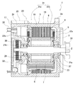
図1は、本発明の一実施形態に係る電動モータの概略構成を示す縦断面図である。電動モータ(以下、ブラシレスモータという)1は、インナーロータ型のブラシレスモータである。図1に示すように、ブラシレスモータ1は、回転軸2に同行回転可能に連結された環状のロータ3と、ロータ3の周囲を取り囲む環状のステータ4と、ロータ3およびステータ4を収容する第1のハウジング16と第2のハウジング17とで構成される筒状のハウジング(以下、モータハウジングという)5とを備えている。例えば、コラムアシストタイプEPS用モータの場合、図1中、ブラシレスモータ1の軸線方向右側に図示しないウォーム減速機、左側に図示しないECUが配置されている。
Hereinafter , as an example of an embodiment of the present invention, an electric motor used in an electric power steering apparatus will be described with reference to the drawings.
FIG. 1 is a longitudinal sectional view showing a schematic configuration of an electric motor according to an embodiment of the present invention. An electric motor (hereinafter, referred to as a brushless motor) 1 is a inner over-rotor brushless motor. As shown in FIG. 1, the
ロータ3は、回転軸2に同軸的に連結された環状のロータコア6と、このロータコア6の外周に固定された複数枚の永久磁石7とを備えている。永久磁石7は、複数のセグメント磁極を有する多極磁石であり、永久磁石7の外周面の磁極は、N極およびS極が永久磁石7の周方向に交互に入れ替わっている。永久磁石7は、例えば10極のセグメント磁極を有している。
The
ステータ4は、環状のステータコア8と、このステータコア8に巻回された複数のコイル9とを含む。ステータコア8は、電磁鋼板を打ち抜いて所定の形状に形成された複数枚の薄板がロータ3の回転軸2の軸線方向に積層固定された積層体である。すなわち、ステータコア8は、鉄を含む材料により形成されている。電磁鋼板としては、例えば、表面に絶縁処理が施された珪素鋼板等を用いることができる。
The stator 4 includes an annular stator core 8 and a plurality of
図1を参照して、モータハウジング5は、一端が開放された筒状の第1のハウジング16と、この第1のハウジング16に嵌合された筒状の第2のハウジング17とを含む。第1のハウジング16および第2のハウジング17は、それぞれ例えば、炭素鋼等の鉄、または、アルミニウムを含む材料によって形成されている。
Referring to FIG. 1, the
第1のハウジング16は、第1の筒状部19と、この第1の筒状部19の一端から第1の筒状部19の径方向外方に突出する第1のフランジ部20と、第1の筒状部19の他端から第1の筒状部19の径方向内方に延び回転軸2が挿通する第1の挿通孔21aが中心部に形成された環状部22aとを含む。環状部22aの内周部には、軸受37が保持された軸受保持部23が形成されている。
The
第1のハウジング16の、第1の筒状部19は、軸線方向に関してステータコア8よりも長くされている。第1の筒状部19の内周には、焼嵌めまたは圧入によってステータコア8が固定されている。すなわち、第1のハウジング16とステータコア8とは嵌合により接合されている。
The first
第2のハウジング17は、第1のハウジング16の第1の筒状部19の外周部に沿って連結された第2の筒状部24と、第2の筒状部24の後方端部から第2の筒状部24の径方向内方に延び回転軸2が挿通する第2の挿通孔21bが中心部に形成された第2の環状部22bと、この第2の筒状部24の外周面から第2の筒状部24の径方向外方に突出する第2のフランジ部25とを含む。第2のハウジング17の環状部22bのステータコア8側の中心部には、軸受38が保持された軸受保持部29が形成されている。また、環状部22bの反対側には回転軸2に装着されたレゾルバ32がロータ3の回転位置を検出する回転角センサとして配置されている。そして、回転軸2は、軸受保持部23に保持された軸受37と、軸受保持部29に保持された軸受38とを介して回転可能にモータハウジング5に保持されている。
The
第2のフランジ部25は、第1のフランジ部20に重なり合わされている。第1のフランジ部20および第2のフランジ部25は、固定手段としての図示しない複数(例えば、本実施形態では、3箇所)のボルトおよび第2のフランジ部25に設けられたねじ部によって、締結固定されている。
The
これにより、第1のハウジング16の一端および第2のハウジング17の一端が固定され、第1のハウジング16に対する第2のハウジング17の回転が防止されている。すなわち、複数のボルトおよびナット、ならびに、第1のフランジ部20および第2のフランジ部25は、第1のハウジング16に対する第2のハウジング17の回転を防止する回転防止手段として機能している。
Thereby, one end of the
また、ブラシレスモータ1を制御するための図示しないECUが第2のハウジング17の環状部22bの後方端面(図1中、左側)に取り付けられ第2のフランジ部25にねじ止め固定されている。各コイル9と接続されインシュレータ31に絶縁支持されたブラシレスモータ1の各相の出力端子である金属製のバスバー30は、ECUの基板に挿通され、基板上のインバータ回路部にねじ止めして接続されている。そして、上記構成により、ECUによって制御された駆動電流がブラシレスモータ1の各コイル9に供給される。これにより、コイル9に回転磁界が発生し、永久磁石7にトルクが生じてロータ3が回転駆動される。また、レゾルバ32も同様に信号入出力端子であるリード線がECUの基板にハンダ付けにより接続されている。
An ECU (not shown) for controlling the
ブラシレスモータ1は、第1のハウジング16の第1の筒状部19の軸線方向左端から第1の筒状部19の径方向外方に突出する第3のフランジ部28により、例えば、コラムアシストタイプの電動パワーステアリング装置において、図示しないウォーム減速機に取り付け固定され、回転軸2に取り付けられたトルクを伝達するボス33を介してウォーム軸回転軸に結合されている。
The
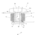
次に、コイル9(図1参照)が設けられる前のステータ4の図を示す。図2は、図1のステータの概略構成を示す平面図である。ステータ4では、複数(本実施形態では、12個)のステータコア8のティース部11が、環状の外径部(ヨーク部)10から回転軸2(図1参照)に向って突出して設けられており、各ティース部11の内側先端には、回転軸2を中心として周方向において両側に広がる磁極部12が設けられる。積層された各ティース部11の回転軸2の軸線方向の長さは、ティース部11の周方向の幅よりも大きく、また、周方向における各ティース部11の両側面は、回転軸2の軸線方向に平行とされる。
Next, the figure of the stator 4 before the coil 9 (refer FIG. 1) is provided is shown. FIG. 2 is a plan view showing a schematic configuration of the stator of FIG. In stator 4, a plurality (in this embodiment, twelve)
図2に示すように、各ティース部11は、インシュレータ31により覆われている。また、ヨーク部10の軸線方向端面の一部、磁極部12の軸線方向端面のほぼ全体は、インシュレータ31により覆われている。ヨーク部10、ティース部11および磁極部12は、これらに対応する形状の珪素鋼板が軸線方向に複数枚積層されて形成されている。インシュレータ31は、各ティース部11およびその周辺部と、コイル9との電気的絶縁を図るために設けられ、ステータコア8の軸線方向両端に装着されている。インシュレータ31は、樹脂材料(例えば、ガラス繊維強化PPS)により形成されている。
As shown in FIG. 2, each
各インシュレータ31は、図2に示すように、ティース部11の上端を覆うヨーク部10において、コイル9を形成するコイル線(導線、後述する)の直径にほぼ等しいピッチにて平行に配列されてコイル線の巻き付け位置を規制する複数のガイド溝14を備えている。複数のガイド溝14は、回転軸2に平行であってティース部11の回転軸中心J1に向って垂直な面に対して平行に設けられる。1つのガイド溝14は、軸線方向にティース部11の一方側の端面および両側面にわたって連続して形成されている。また、ティース部11の図示しない反対側の端面および両側面にわたってもガイド溝14が連続して形成されている。
As shown in FIG. 2, the
次に、図3および図4は、図2中において最も上側に位置するインシュレータ31近傍を拡大して示す図である。図3は、インシュレータを示す平面図、図4は、インシュレータを示す側面図である。インシュレータ31は、ティース部11の軸線方向における中央から一方側(図1中、左側)を覆う複数のガイド溝14が設けられた樹脂成形品である第1インシュレータ31aおよび第1インシュレータ31aを反転して配置した他方側(図1中、右側)を覆う第2インシュレータ31bからなり、分割された第1,2インシュレータ31a,31bが軸線方向両側からティース部11(図2参照)に嵌め込まれて形成されている。ここで、第1インシュレータ31aは、コイル線13の巻き始め、および巻き終り側のインシュレータである。
Next, FIGS. 3 and 4 are enlarged views showing the vicinity of the
コイル9が形成される際には、図3に示す第1インシュレータ31aの端部において、1段目のコイル線13が左側から右側へとガイド溝14に沿って第1インシュレータ31aに巻き付けられる(図3中、一点鎖線にて示す)。ここで、各コイル線13はガイド溝14のピッチdに等しく内径側にずれた傾きをもって平行に巻き付けられる。これにより、各コイル線13は、第1インシュレータ31aの外周を1周する毎に1ピッチ分だけ内径方向に移動するように巻回される。続いて、2段目のコイル線13が1段目のコイル線13と交差して巻き付けられる。また、第1インシュレータ31aとは反対側の第2インシュレータ31bの端部において、各コイル線13はガイド溝14に沿って水平方向に巻き付けられる。
When the
図3、4に示すように、第1インシュレータ31aの端部には、複数のガイド溝14上に軸線方向に積層されるコイル線13が側方に崩れることを防止するための2つの側壁(突出部)26,27が設けられている。以下、インシュレータ31の外径側に設けられた側壁を外径側壁26といい、内径側に設けられた側壁を内径側壁27という。側壁26,27は、コイル線13の積層方向である軸線方向Zに延びている。
As shown in FIGS. 3 and 4, at the end of the
図3に示すように、第1インシュレータ31aの外径側壁26は、径方向内側にそれぞれ傾斜した当接部位34,35を備えている。図3の一点鎖線に示すように、巻き始めにおいて、当接部位34はコイル線13がガイド溝14に向かうように傾斜している。当接部位35は逆方向に同角度に傾斜し、巻き終りのコイル線13をガイドする。この内面の当接部位34,35の頂点(先端部P)がコイル9の外径側端部Bとの間にガイド溝14のピッチdのほぼ1/2の隙間を有している。また、内径側壁27は、回転軸中心J1に向かって垂直な径方向外側の傾斜面Cの水平端部Dがコイル9の内径側端部Aとほぼ同一の高さhになるように形成されている。コイル9の1段目は、巻き始めのコイル線13が当接部位34と接し、最終列のコイル線13が当接部位36と接して巻回方向(図3中、右方向)にガイドされる。また、4段目は、巻き終りのコイル線13が当接部位35と接してガイドされ取り出される。
As shown in FIG. 3, the outer
さらに、図4に示すように、第1インシュレータ31aの端部において、コイル線13は1周毎に内径方向に次の列に移って巻回され、コイル線13が係合する係合部15は、ガイド溝14がない平面状に形成されている。1段目の各コイル線13は、周回ごとに第1インシュレータ31a端部の平面状の係合部15に接して、ガイド溝14のピッチdにて傾斜して平行に配列され、隣接するコイル線13と互いに接するように隙間なく巻回される(図4中、一点鎖線にて示す)。巻回方向に導かれたコイル線13は、第1インシュレータ31a側面に軸線方向と平行に設けられたガイド溝14に沿って図4中、右方向へ延びて巻回されている。そして、図3中の巻き始めの一点鎖線と巻き終りの一点鎖線とは、先端部P付近で交差する位置Eをなすようにステータコア8(図2参照)に巻回される。
Further, as shown in FIG. 4, at the end of the
次に、上記のように構成された本実施形態であるブラシレスモータ1の作用および効果について説明する。
Next, operations and effects of the
上記構成によれば、第1インシュレータ31aの外径側壁26は、径方向内側にそれぞれ傾斜した当接部位34,35を備え、巻き始めにおいて、当接部位34はコイル線13がガイド溝14に向かうように傾斜し、当接部位35は逆方向に同角度に傾斜し、巻き終りのコイル線13をガイドする。この内面の当接部位34,35の先端部Pがコイル9の外径側端部Bとの間にガイド溝14のピッチdのほぼ1/2の隙間を有している。また、内径側壁27は、径方向外側の傾斜面Cの水平端部Dがコイル9の内径側端部Aとほぼ同一の高さhになるように形成されている。さらに、第1インシュレータ31aの端部において、コイル線13は1周毎に内径方向に次の列に移って巻回され、コイル線13が係合する係合部15は、ガイド溝14がない平面状に形成されている。1段目の各コイル線13は、周回ごとに第1インシュレータ31a端部の平面状の係合部15に接して、ガイド溝14のピッチdにて傾斜して平行に配列され、隣接するコイル線13と互いに接するように隙間なく巻回される。巻回方向に導かれたコイル線13は、第1インシュレータ31a側面に軸線方向と平行に設けられたガイド溝14に沿って巻回されている。そして、巻き始めのコイル線14と巻き終りのコイル線14とは、先端部P付近で交差する位置Eをなすようにステータコア8に巻回される。
According to the above configuration, the outer
これにより、外径側での巻き始めのコイル線13が1段目のコイル線13に干渉、および内径側で最終列のコイル線13が内径側壁27に乗り上げることが抑制される。その結果、第1インシュレータ31aの外径側壁26および内径側壁27にかかる応力が減少し、インシュレータ31aの破損を防止できる。また、コイル線13の巻き崩れを抑制し整列して巻回できる。その結果、コイル9の占積率が向上し、ブラシレスモータ1を小型化できるとともに、ブラシレスモータ1の性能向上につながる。
As a result, the
さらに、第1および第2インシュレータ31a,31bを共通化して製造することにより、あるいはインシュレータ31の樹脂強度に影響を与えるガラスフィラー等の添加量を削減できることにより低価格の部材が選定可能になり、製造コストの低減を図ることができる。
Furthermore, by making the first and
以上のように、本実施形態によれば、ステータコアに設けるコイルの巻き崩れを防止し、コイルの占積率を高めることができるブラシレスモータを提供できる。 As described above, according to the present embodiment, it is possible to provide a brushless motor that can prevent the coil provided on the stator core from collapsing and increase the coil space factor.
以上、本発明に係る実施形態について説明したが、本発明はさらに他の形態で実施することも可能である。
上記実施形態では、第1および第2インシュレータ31a,31bに同じ形状の部品を使用したが、これに限らず、第2インシュレータ31bの端部に平行なガイド溝14を設け、さらに、外径および内径側壁26,27の内面側は、水平に形成されていてもよい。
As mentioned above, although embodiment which concerns on this invention was described, this invention can also be implemented with another form.
In the above embodiment, parts having the same shape are used for the first and
また、上記実施形態では、複数のティース部11に装着されるインシュレータ31は、分割形状を示したが、これに限らず、円環状に連結あるいは一体成形された第1インシュレータ31aと同じく連結あるいは一体成形された第2インシュレータ31bとにより構成されていてもよい。また、インシュレータ31は、ステータコア8に樹脂モールドすることにより形成されていてもよい。
Moreover, in the said embodiment, although the
上記実施形態では、ステータ4は、分割型コアとしたが、これに限らず、一体型コアであってもよい。また、ステータ4が設けられるブラシレスモータ1は、インナーロータ型に限定されず、アウターロータ型であってもよい。
In the above embodiment, the stator 4 is a split core, but is not limited thereto, and may be an integral core. The
また、上記実施形態では、ブラシレスモータ1を電動パワーステアリング装置(EPS)のいわゆるコラムアシストタイプに適用した例を示したが、これに限らず、ピニオンアシストタイプやラックアシストタイプの電動パワーステアリング装置に適用してもよい。また、同様のブラシレスモータを用いた他の装置(例えば、電動オイルポンプ装置等)に適用してもよい。
In the above embodiment, the
1:ブラシレスモータ(電動モータ)、2:回転軸、3:ロータ、4:ステータ、
5:モータハウジング、6:ロータコア、7:永久磁石、8:ステータコア、
9:コイル、10:ヨーク部、11:ティース部、12:磁極部、
13:コイル線(導線)、14:ガイド溝、15:係合部、16:第1のハウジング、
17:第2のハウジング、19:第1の筒状部、20,25,28:フランジ部、
21a,21b:挿通孔、22a,22b:環状部、23,29:軸受保持部、
24:第2の筒状部、26:外径側壁(突出部)、27:内径側壁(突出部)、
30:バスバー、31:インシュレータ、31a,31b:第1,第2インシュレータ、32:レゾルバ、33:ボス、34,35:外径側壁の当接部位、
36:内径側壁の当接部位、37,38:軸受、J1:回転軸中心、
d:ピッチ、A:コイル内径側端部、B:コイル外径側端部、C:内径側壁傾斜面、
D:内径側壁傾斜面の水平端部、E:巻き始めと巻き終りの交点、P:先端部、
Z:コイルの積層方向である軸線方向
1: brushless motor (electric motor), 2: rotating shaft, 3: rotor, 4: stator,
5: motor housing, 6: rotor core, 7: permanent magnet, 8: stator core,
9: Coil, 10: Yoke part, 11: Teeth part, 12: Magnetic pole part,
13: Coil wire (conductive wire), 14: Guide groove, 15: Engaging portion, 16: First housing,
17: 2nd housing, 19: 1st cylindrical part, 20, 25, 28: Flange part,
21a, 21b: insertion hole, 22a, 22b: annular part, 23, 29: bearing holding part,
24: 2nd cylindrical part, 26: Outer diameter side wall (protrusion part), 27: Inner diameter side wall (protrusion part),
30: Bus bar, 31: Insulator, 31a, 31b: First and second insulators, 32: Resolver, 33: Boss, 34, 35: Abutting portion of outer diameter side wall,
36: contact part of inner diameter side wall, 37, 38: bearing, J1: center of rotation axis,
d: pitch, A: a coil inner diameter side end portion, B: coil outer diameter end, C: inner diameter side wall inclined surface,
D: horizontal edge of the inner diameter side wall inclined surface, E: winding start and winding the intersection of end, P: tip,
Z: Axial direction which is the lamination direction of coils
Claims (2)
前記各ステータコアを覆うインシュレータと、
前記各ステータコアの前記ティース部に前記インシュレータ上から多層に導線を巻回することにより設けられたコイルと、を備えてハウジング内に固定されたステータと、
前記ステータの前記ティース部の内側先端の磁極部で形成される内周面と対向しながら前記ハウジングで回転可能に支承された前記回転軸線上のロータと、を備えた電動モータにおいて、
前記インシュレータは、前記回転軸線の方向の側面外周に形成され前記導線の直径にほぼ等しいピッチで平行に配列されて前記コイルをガイドするガイド溝と、
前記回転軸線の方向の両端部において、前記電動モータの外径側および内径側に一体形成され、前記導線の積層方向に突出して設けられるとともに、前記導線の巻き付け位置を規制し前記コイルに当接する突出部と、を有し、
前記インシュレータの少なくとも一端部において、前記導線が前記ガイド溝に向かうように傾斜した外径側前記突出部の当接部位の先端部と前記コイルの外径側端部との間に前記ガイド溝の前記ピッチの1/2の隙間を有し、前記コイルの内径側内側最終列の前記導線が前記コイルの内径側端部に向かうように当接する内径側前記突出部の径方向外側傾斜面の端部が前記コイルの内径側端部と径方向にほぼ同一の高さになるように形成されていることを特徴とする電動モータ。 A plurality of stator cores each having an arcuate yoke portion and a teeth portion projecting radially inward from the yoke portion, and arranged annularly around a rotation axis;
An insulator covering each stator core;
A coil provided by winding a conductive wire in multiple layers from the insulator on the teeth portion of each stator core; and a stator fixed in a housing;
An electric motor comprising: a rotor on the rotational axis that is rotatably supported by the housing while facing an inner peripheral surface formed by a magnetic pole portion at an inner tip of the teeth portion of the stator.
The insulator is formed on the outer periphery of the side surface in the direction of the rotation axis, and is arranged in parallel at a pitch substantially equal to the diameter of the conducting wire to guide the coil, and
At both ends in the direction of the rotation axis, the electric motor is integrally formed on the outer diameter side and the inner diameter side, and is provided so as to protrude in the laminating direction of the conductive wire, and regulates the winding position of the conductive wire and contacts the coil. A protrusion, and
In at least one end of the insulator, the guide groove is formed between the tip of the contact portion of the protruding portion on the outer diameter side and the outer diameter side end of the coil inclined so that the lead wire faces the guide groove. An end of the radially outer inclined surface of the projecting portion on the inner diameter side , which has a gap of 1/2 of the pitch, and contacts the inner diameter side inner last row of the coil toward the inner diameter side end of the coil The electric motor is characterized in that the portion is formed to have substantially the same height in the radial direction as the inner diameter side end of the coil.
前記インシュレータは、前記一端部において、周回ごとに傾斜して前記ピッチにて平行に巻回される前記導線が係合する係合部が平面状に形成されていることを特徴とする電動モータ。 The electric motor according to claim 1,
The electric motor according to claim 1, wherein an engaging portion is formed in a planar shape at the one end portion to engage with the conducting wire that is inclined at each turn and wound in parallel at the pitch.
Priority Applications (1)
| Application Number | Priority Date | Filing Date | Title |
|---|---|---|---|
| JP2012160364A JP6065436B2 (en) | 2012-07-19 | 2012-07-19 | Electric motor |
Applications Claiming Priority (1)
| Application Number | Priority Date | Filing Date | Title |
|---|---|---|---|
| JP2012160364A JP6065436B2 (en) | 2012-07-19 | 2012-07-19 | Electric motor |
Publications (3)
| Publication Number | Publication Date |
|---|---|
| JP2014023299A JP2014023299A (en) | 2014-02-03 |
| JP2014023299A5 JP2014023299A5 (en) | 2015-09-10 |
| JP6065436B2 true JP6065436B2 (en) | 2017-01-25 |
Family
ID=50197624
Family Applications (1)
| Application Number | Title | Priority Date | Filing Date |
|---|---|---|---|
| JP2012160364A Expired - Fee Related JP6065436B2 (en) | 2012-07-19 | 2012-07-19 | Electric motor |
Country Status (1)
| Country | Link |
|---|---|
| JP (1) | JP6065436B2 (en) |
Families Citing this family (2)
| Publication number | Priority date | Publication date | Assignee | Title |
|---|---|---|---|---|
| JP7194624B2 (en) * | 2019-03-27 | 2022-12-22 | 株式会社山田製作所 | insulator |
| JP7445914B2 (en) | 2020-02-07 | 2024-03-08 | パナソニックIpマネジメント株式会社 | Winding frame member, stator, motor, and method for manufacturing the winding frame member including the same |
Family Cites Families (4)
| Publication number | Priority date | Publication date | Assignee | Title |
|---|---|---|---|---|
| JPS5346538U (en) * | 1976-09-25 | 1978-04-20 | ||
| JPH02209703A (en) * | 1989-02-09 | 1990-08-21 | Matsushita Electric Ind Co Ltd | Coil bobbin |
| JP4402976B2 (en) * | 2004-02-12 | 2010-01-20 | 三工機器株式会社 | Insulator for stator core and winding method for stator core |
| JP5273448B2 (en) * | 2008-06-17 | 2013-08-28 | 日本電産株式会社 | motor |
-
2012
- 2012-07-19 JP JP2012160364A patent/JP6065436B2/en not_active Expired - Fee Related
Also Published As
| Publication number | Publication date |
|---|---|
| JP2014023299A (en) | 2014-02-03 |
Similar Documents
| Publication | Publication Date | Title |
|---|---|---|
| US8030812B2 (en) | Rotating electric apparatus and method for connecting stator coils thereof | |
| JP5028869B2 (en) | Brushless motor | |
| JP5070248B2 (en) | Rotating electric machine and manufacturing method thereof | |
| US9680358B2 (en) | Method for manufacturing a winding body that is used in an armature winding for an electric machine | |
| US20160218578A1 (en) | Bus bar unit, method for manufacturing bus bar unit, and brushless motor | |
| JP5523112B2 (en) | Brushless motor | |
| EP2940834B1 (en) | Motor | |
| JP6120987B2 (en) | Armature of electric machine | |
| WO2013145976A1 (en) | Stator structure for rotary electric machine | |
| WO2009119734A1 (en) | Motor | |
| US20150311760A1 (en) | Brushless motor | |
| US20110084562A1 (en) | Motor | |
| EP2445088A2 (en) | Brushless motor and electric power steering system | |
| JPWO2015029579A1 (en) | Rotating electric machine | |
| WO2016006310A1 (en) | Stator coil, stator, electromagnetic device, and production method for stator coil | |
| US10547219B2 (en) | Rotating electric machine having air core coil with curved end surfaces | |
| JP2009213283A (en) | Brushless motor | |
| JP2011135733A (en) | Rotating electric machine | |
| JP6065436B2 (en) | Electric motor | |
| JP5948392B2 (en) | Rotating electric machine, stator and stator winding | |
| JP5667803B2 (en) | Rotating electrical machine rotor | |
| JP6373494B2 (en) | Rotating electric machine | |
| US11223246B2 (en) | Stator | |
| JP2014023299A5 (en) | ||
| JP2009213282A (en) | Brushless motor |
Legal Events
| Date | Code | Title | Description |
|---|---|---|---|
| A621 | Written request for application examination |
Free format text: JAPANESE INTERMEDIATE CODE: A621 Effective date: 20150623 |
|
| A521 | Request for written amendment filed |
Free format text: JAPANESE INTERMEDIATE CODE: A523 Effective date: 20150721 |
|
| A977 | Report on retrieval |
Free format text: JAPANESE INTERMEDIATE CODE: A971007 Effective date: 20160510 |
|
| A131 | Notification of reasons for refusal |
Free format text: JAPANESE INTERMEDIATE CODE: A131 Effective date: 20160524 |
|
| A521 | Request for written amendment filed |
Free format text: JAPANESE INTERMEDIATE CODE: A523 Effective date: 20160623 |
|
| TRDD | Decision of grant or rejection written | ||
| A01 | Written decision to grant a patent or to grant a registration (utility model) |
Free format text: JAPANESE INTERMEDIATE CODE: A01 Effective date: 20161129 |
|
| A61 | First payment of annual fees (during grant procedure) |
Free format text: JAPANESE INTERMEDIATE CODE: A61 Effective date: 20161212 |
|
| R150 | Certificate of patent or registration of utility model |
Ref document number: 6065436 Country of ref document: JP Free format text: JAPANESE INTERMEDIATE CODE: R150 |
|
| LAPS | Cancellation because of no payment of annual fees |