EP3200323B1 - Motor for use in refrigerant environment - Google Patents
Motor for use in refrigerant environment Download PDFInfo
- Publication number
- EP3200323B1 EP3200323B1 EP17153201.3A EP17153201A EP3200323B1 EP 3200323 B1 EP3200323 B1 EP 3200323B1 EP 17153201 A EP17153201 A EP 17153201A EP 3200323 B1 EP3200323 B1 EP 3200323B1
- Authority
- EP
- European Patent Office
- Prior art keywords
- stator
- motor
- shell
- accordance
- coils
- Prior art date
- Legal status (The legal status is an assumption and is not a legal conclusion. Google has not performed a legal analysis and makes no representation as to the accuracy of the status listed.)
- Active
Links
Images


Classifications
-
- F—MECHANICAL ENGINEERING; LIGHTING; HEATING; WEAPONS; BLASTING
- F25—REFRIGERATION OR COOLING; COMBINED HEATING AND REFRIGERATION SYSTEMS; HEAT PUMP SYSTEMS; MANUFACTURE OR STORAGE OF ICE; LIQUEFACTION SOLIDIFICATION OF GASES
- F25B—REFRIGERATION MACHINES, PLANTS OR SYSTEMS; COMBINED HEATING AND REFRIGERATION SYSTEMS; HEAT PUMP SYSTEMS
- F25B31/00—Compressor arrangements
- F25B31/02—Compressor arrangements of motor-compressor units
- F25B31/026—Compressor arrangements of motor-compressor units with compressor of rotary type
-
- H—ELECTRICITY
- H02—GENERATION; CONVERSION OR DISTRIBUTION OF ELECTRIC POWER
- H02K—DYNAMO-ELECTRIC MACHINES
- H02K15/00—Processes or apparatus specially adapted for manufacturing, assembling, maintaining or repairing of dynamo-electric machines
- H02K15/02—Processes or apparatus specially adapted for manufacturing, assembling, maintaining or repairing of dynamo-electric machines of stator or rotor bodies
- H02K15/021—Magnetic cores
- H02K15/026—Wound cores
-
- H—ELECTRICITY
- H02—GENERATION; CONVERSION OR DISTRIBUTION OF ELECTRIC POWER
- H02K—DYNAMO-ELECTRIC MACHINES
- H02K3/00—Details of windings
- H02K3/04—Windings characterised by the conductor shape, form or construction, e.g. with bar conductors
- H02K3/28—Layout of windings or of connections between windings
-
- H—ELECTRICITY
- H02—GENERATION; CONVERSION OR DISTRIBUTION OF ELECTRIC POWER
- H02K—DYNAMO-ELECTRIC MACHINES
- H02K3/00—Details of windings
- H02K3/30—Windings characterised by the insulating material
-
- H—ELECTRICITY
- H02—GENERATION; CONVERSION OR DISTRIBUTION OF ELECTRIC POWER
- H02K—DYNAMO-ELECTRIC MACHINES
- H02K3/00—Details of windings
- H02K3/44—Protection against moisture or chemical attack; Windings specially adapted for operation in liquid or gas
-
- H—ELECTRICITY
- H02—GENERATION; CONVERSION OR DISTRIBUTION OF ELECTRIC POWER
- H02K—DYNAMO-ELECTRIC MACHINES
- H02K3/00—Details of windings
- H02K3/46—Fastening of windings on the stator or rotor structure
- H02K3/48—Fastening of windings on the stator or rotor structure in slots
- H02K3/487—Slot-closing devices
-
- H—ELECTRICITY
- H02—GENERATION; CONVERSION OR DISTRIBUTION OF ELECTRIC POWER
- H02K—DYNAMO-ELECTRIC MACHINES
- H02K3/00—Details of windings
- H02K3/46—Fastening of windings on the stator or rotor structure
- H02K3/50—Fastening of winding heads, equalising connectors, or connections thereto
Definitions
- the present invention relates to electric motors for use in an ammonia environment. More specifically, the present invention relates to motors for use in an ammonia environment.
- EP 1291528 A2 discloses a scroll compressor and a refrigerating system using an ammonia group refrigerant.
- US 3,688,137 A discloses in a general way electric machines of the open type intended to operate in a fluid medium or in a corrosive atmosphere.
- US 2009/191074 A1 discloses an electrically powered pump that has an electric motor arrangement for driving a pump arrangement.
- a motor for use in a refrigerant atmosphere is defined in claim 1.
- FIG. 1 illustrates a refrigeration system 10 that includes a compressor chamber 15 that contains a compressor 20 driven by an electric motor 25.
- the refrigeration system 10 also includes an evaporator 31, a condenser 32, and an expansion valve 33.
- the refrigeration system 10 is adapted for use with a refrigeration fluid such as ammonia.
- the ammonia is refrigerant grade R-717 ammonia.
- the compressor 20 could include one of a variety of different types of compressors including rotary screw, reciprocating, scroll, centrifugal, and the like.
- the actual style of compressor employed is not critical to the invention. Rather, all that is required is that the compressor 20 includes a stationary portion and a rotary portion coupled to a compressor shaft.
- the motor 25 may be a hermetic motor specifically designed to be submerged within a refrigerant atmosphere.
- the motor 25 can utilize an external power supply that can be line-fed or inverter-fed.
- Motors 25 for ammonia compressors 20 are typically located outside the compressor chamber 15 and use either a shaft seal or a magnetic coupling to connect the motor 25 to the compressor shaft. This has been necessary because of the chemical aggressiveness of refrigerant (e.g., ammonia) towards standard materials of motor construction. Additionally, exposure to high temperature/pressure ammonia causes typical insulation materials to lose their resistance, which in turn causes premature motor failure.
- the present invention constructs the motor 25 out of materials that are more resistant to ammonia and uses techniques and arrangements that enhance the effectiveness of the materials, thereby allowing the motor 25 to be placed in the ammonia environment while operating satisfactorily for a sufficient length of time.
- the motor 25 and the compressor 20 are positioned inside the compressor chamber 15 to save space and provide the motor 25 the benefit of cooling from the refrigerant.
- This cooling of the motor 25 potentially allows for the use of smaller motors to achieve the same performance.
- placing the motor 25 inside the compressor chamber 15 eliminates any potential leakage paths through external shaft seals.
- placing the motor 25 inside the compressor chamber 15 allows for a lower cost unit due to the elimination of duplicate brackets and bearings required to connect the motor externally.
- the compressor shaft can also be made shorter, shaft seals are eliminated, and magnetic couplings are not needed.
- the motor 25 employs a Variable Frequency Drive (VFD) 30 to improve the efficiency of the refrigeration system 10 when compared to more conventional line-fed systems.
- VFD 30 utilizes a control system that is sensitive to motor current draw and system leakage current.
- the motor construction must be modified to assure that there are little or no areas in which the ammonia can make contact with electrically conductive areas within the motor windings or inter-pole connections. Because ammonia has a higher conductivity to electrical current then typical refrigerants used in hermetic compressors and because the motor stator resides in the ammonia, leakage current that might occur will likely be larger than on a motor not disposed in ammonia. Such current leakages would be more likely to cause the VFD motor protection to remove power to the motor 25. To reduce this likelihood, the motor 25 incorporates a stator winding in which no internal connections are present (i.e., each phase winding is continuous). The elimination of internal connections reduces the likelihood of any potential for leakage current to exist due to the ammonia refrigerant.
- the motor 25 includes a stator 35 and a rotor 40 disposed adjacent the stator 35 and drivingly connected to the driven shaft of the compressor 20.
- the rotor 40 includes a portion disposed within a cavity 45 of the stator 35.
- other motor arrangements could also be employed to drive the compressor 20.
- the electric motor 25 is positioned within the refrigeration system 10 such that it is directly coupled to the compressor 20 and such that it is directly exposed to the refrigerant, in the illustrated example ammonia. Positioning the motor 25 in this way provides for more efficient transfer of power between the motor 25 and the compressor 20 and also provides more effective cooling of the motor 25 using the refrigerant as a coolant. However, refrigerant can be detrimental to many typical motor components.
- the stator 35 defines a cavity 45 that receives a portion of the rotor 40.
- the stator 35 includes a core 50 defining opposite end portions 55, 60.
- the stator core 50 includes a plurality of circumferentially spaced stacked metal laminations 65 disposed parallel to a centerline 70 of the cavity 45.
- the metal laminations 65 may consist of electrical grade lamination steel with other materials or constructions such as powdered metal portions being possible.
- the stator core 50 includes a plurality of teeth 75 that each defines a pair of circumferentially spaced longitudinal slot walls 80.
- the slot walls 80 of adjacent teeth 75 cooperate with one another to define longitudinal slots 85 in the periphery of the stator 35.
- Each tooth also defines two hooks 90.
- Circumferentially spaced coils are arranged with each coil disposed on one of the teeth 75 such that each coil is disposed at least partially in two slots 85.
- Each coil consists of a plurality of windings of wire 95 with portions of the windings of wire 95 extending longitudinally in the slots 85 in which the coil resides.
- each coil is defined by a plurality of windings of the wire 95 repeatedly passing through a first slot 85a, around the first end portion 55, passing through a second slot 85b adjacent the first slot 85a, around the second end portion 60, and again through the first slot 85a.
- the wire 95 consists of conductive material 100 immediately surrounded by wire insulation 105.
- copper or aluminum wire 100 is used as the conductor 100 with aluminum being favored in an ammonia environment.
- Polyetheretherketone (PEEK) material may be used to form the insulation 105. While some constructions may use conductors 100 coated with PEEK insulation 105, extruded PEEK insulation 105 may also be used as testing has shown significant performance increases using this construction. Specifically, the extruded PEEK insulation 105 exhibits improved toughness and superior dielectric properties when compared to coated insulation.
- Slot liners 110 are provided in the slots 85 between the windings of wire 95 and the respective slot walls 80 to further insulate the windings 95 from the magnetic core 50.
- the slot liners 110 are formed from sheets of polyphenylene sulfide (PPS). While various thicknesses of slot liners 110 are possible, slot liners 110 that are between about 0.01 and about 0.02 inches (0.25 to 0.5 mm) in thickness may be used in some constructions. The sheet material provides better formability and more robust properties than other materials that were tested.
- the stator 35 may include interphase insulators 115, sometimes referred to as phase paper, between the coils to further insulate the different phases of the motor 25.
- phase paper 15 is employed and is made using sheets of a polyphenylene sulfide (PPS) material similar to that of the slot liners 110. As with the slot liners 110, the sheets provided improved characteristics when compared to other material choices.
- PPS polyphenylene sulfide
- wedges 120 are typically positioned within the slots 85 to take up this space, assure that the individual windings of wire 95 are packed as tightly as possible, and to limit unwanted movement of the wires 95.
- longitudinally extending wedges 120 are employed. Each wedge 120 is positioned between a respective slot liner 110 and the stack of windings 95 within the slot 85. The wedge 120 engages the underside of two adjacent hooks 90 formed as part of the adjacent teeth 75 to apply a compressive force to the wires 95.
- pegs are positioned between the wires 95 and the wedge 120 to take up additional space and to provide a flatter engagement surface for the wedges 120. While many materials are available for wedges 120 and pegs, some constructions may employ wedges 120, and pegs if used, that are formed from one of an epoxide laminate, a polyphenylene sulfide (PPS), and a polyetheretherketone (PEEK) material. The wedges 120 and pegs (if employed) are secured in interlocking relationship with the stator core 50 to prevent radially outward movement of the coils 95 relative to the stator core 50. It should be noted that any combination of the three identified materials could be employed for the construction of the stator 35.
- pegs could be formed from a PEEK material with wedges 120 formed from PPS if desired.
- components could be manufactured as composites.
- pegs or wedges 120 could be formed with a wood core that is coated or covered with extruded PEEK, PPS, or epoxide laminate material.
- the stator 35 includes lacing cord 125 laced about the end turns of the coils.
- the lacing 125 tightly secures the end turns of the coils, thereby reducing unwanted movement or vibration.
- Lacing tape 125 may be formed from a NOMEX ® tape.
- other constructions may use other materials (e.g., KEVLAR ® , other meta-aramids, para-aramids, etc.) for lacing 125.
- the stator 35 also includes lead wire 130 that provides for a connection between the coils and the source of electrical power.
- the lead wire 130 includes conductive material 125 (e.g., copper, aluminum, etc.) immediately surrounded by lead wire insulation 140.
- conductive material 125 e.g., copper, aluminum, etc.
- lead wire insulation 140 e.g., one construction employs conductive material 135 consisting of wound strands of aluminum with lead wire insulation 140 formed from a fluoropolymer such as TEFLON ® (i.e., polytetrafluoroethylene (PTFE)).
- TEFLON ® i.e., polytetrafluoroethylene (PTFE)
- the insulating material is provided in the form of a tape that is wrapped in overlapping relationship about the conductor 135 such that the proportion of tape overlap is at least about 50%.
- the lead wire insulation 140 may include TEFLON ® tape wrapped in overlapping relationship and strands or filaments of fiberglass overbraided over the TEFLON ® tape.
- the fiberglass filaments provide a flexible abrasion-resistant covering over the TEFLON ® tape.
- the motor can be leadless, such that the wire is directly connected to power terminals.
- the stator 35 may also include sleeving 145 which protects the lead wire 130 and further insulates the lead wires 130 from each other at crossovers between the coils.
- the sleeving 145 consists of a fluoropolymer such as TEFLON ® (i.e., polytetrafluoroethylene (PTFE)).
- the shell 150 encapsulates substantially the entire stator 25.
- the shell 150 is free of apertures to reduce the amount of current leakage.
- the shell 150 may be opaque.
- the shell 150 may have any characteristics that enable the motor 25 to operate as described herein.
- the shell 150 includes a low-viscosity epoxy in the form of an amine cured 100% solids epoxy topcoat, such as that available from ARCOR TM Epoxy Technologies, Inc. of South Dennis, MA under the trade name ARCOR TM EE11.
- the shell 150 has an average thickness in a range from about 4 mm to about 10 mm.
- the shell 150 is formed by coating the end turns of the coils and all exposed surfaces of the stator 35 with a liquid that cures to form the shell 150.
- the stator 35 is coated by dipping the stator 35 at least partially in the liquid which adheres to the stator 35 and solidifies to form the shell 150.
- the stator 35 may be coated by trickle application of a liquid that solidifies to form the shell 150.
- the shell 150 may also be formed in any manner that enables the motor 25 to operate as described herein.
- the shell 150 can be used to seal the coils from the ammonia environment, bond the wires 95 together to reduce movement of the wires 95 relative to one another, reduce noise from the motor 25, coat and bond the laminations 65 in the stator 35, and anchor the interphase insulation.
- the shell 150 facilitates protecting the end turns of the coils from nicks or abrasions as the stator 35 is placed in the compressor chamber 15 and during operation of the refrigeration system 10. As a result, the shell 150 increases the resistance of the motor 25 to the ammonia environment and reduces the risk of current leakage from the coils of the stator 35.
- the rotor 40 is formed using conventional materials and techniques.
- the rotor 40 illustrated in FIG. 6 includes a rotor core 155 formed from laminations of electrical grade steel or aluminum stacked along the rotational axis 70 to a desired length. In other constructions, portions of the core 155 may be formed from powdered metal or other components.
- Rotor bars 160 extend the length of the core 155 and are coupled to end rings 165, 170 disposed at each end of the core 155. Bars 160 and end rings 165, 170 may be formed using aluminum with other materials being possible.
- the motor 25 formed of the indicated materials is more resistant to attack by ammonia than prior motors.
- the motor 25 can be mounted in the refrigeration system 10 in contact with ammonia, and the refrigeration system 10 is suitable for operation with the motor 25 in contact with ammonia. Therefore, the refrigeration system 10 can be simply and inexpensively constructed without sealing the motor 25 from the ammonia.
Landscapes
- Engineering & Computer Science (AREA)
- Power Engineering (AREA)
- Manufacturing & Machinery (AREA)
- Physics & Mathematics (AREA)
- Mechanical Engineering (AREA)
- Thermal Sciences (AREA)
- General Engineering & Computer Science (AREA)
- Insulation, Fastening Of Motor, Generator Windings (AREA)
Description
- This application claims priority to
Chinese Patent Application No. 201610055583.7, filed 27 January 2016 U.S. Patent Application No. 15/049937, filed 22 February 2016 (which is a continuation in part ofU.S. Non-provisional Application No. 14/166424, filed 28 January 2014 U.S. Provisional Application No. 61/757380, filed 28 January 2013 - The present invention relates to electric motors for use in an ammonia environment. More specifically, the present invention relates to motors for use in an ammonia environment.
-
EP 1291528 A2 discloses a scroll compressor and a refrigerating system using an ammonia group refrigerant. -
US 3,688,137 A discloses in a general way electric machines of the open type intended to operate in a fluid medium or in a corrosive atmosphere.US 2009/191074 A1 discloses an electrically powered pump that has an electric motor arrangement for driving a pump arrangement. - In one aspect, a motor for use in a refrigerant atmosphere is defined in claim 1.
- In another aspect, a method of assembling a motor for use in a refrigerant atmosphere is defined in claim 3.
- Other aspects of the invention will become apparent by consideration of the detailed description and accompanying drawings.
-
-
FIG. 1 is a schematic illustration of a refrigeration system including a compressor and a motor; -
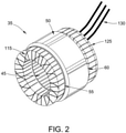
FIG. 2 is a perspective view of a stator; -
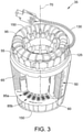
FIG. 3 is a more detailed perspective view of the stator ofFIG. 2 ; -
FIG. 4 is an end view of one of the slots illustrating the wire windings; -
FIG. 5 is a cross-section of one of the winding wires; -
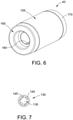
FIG. 6 is a perspective view of a rotor; and -
FIG. 7 is a cross-section of a lead wire. - Before any embodiments of the invention are explained in detail, it is to be understood that the invention is not limited in its application to the details of construction and the arrangement of components set forth in the following description or illustrated in the following drawings. The invention is capable of other embodiments and of being practiced or of being carried out in various ways, within the scope of the invention, which is defined by the appended claims. Also, it is to be understood that the phraseology and terminology used herein is for the purpose of description and should not be regarded as limiting. The use of "including," "comprising," or "having" and variations thereof herein is meant to encompass the items listed thereafter and equivalents thereof as well as additional items. Unless specified or limited otherwise, the terms "mounted," "connected," "supported," and "coupled" and variations thereof are used broadly and encompass both direct and indirect mountings, connections, supports, and couplings. Further, "connected" and "coupled" are not restricted to physical or mechanical connections or couplings.
-
FIG. 1 illustrates arefrigeration system 10 that includes acompressor chamber 15 that contains acompressor 20 driven by anelectric motor 25. Therefrigeration system 10 also includes anevaporator 31, acondenser 32, and anexpansion valve 33. Therefrigeration system 10 is adapted for use with a refrigeration fluid such as ammonia. In one embodiment, the ammonia is refrigerant grade R-717 ammonia. - The
compressor 20 could include one of a variety of different types of compressors including rotary screw, reciprocating, scroll, centrifugal, and the like. The actual style of compressor employed is not critical to the invention. Rather, all that is required is that thecompressor 20 includes a stationary portion and a rotary portion coupled to a compressor shaft. - The
motor 25 may be a hermetic motor specifically designed to be submerged within a refrigerant atmosphere. Themotor 25 can utilize an external power supply that can be line-fed or inverter-fed. -
Motors 25 forammonia compressors 20 are typically located outside thecompressor chamber 15 and use either a shaft seal or a magnetic coupling to connect themotor 25 to the compressor shaft. This has been necessary because of the chemical aggressiveness of refrigerant (e.g., ammonia) towards standard materials of motor construction. Additionally, exposure to high temperature/pressure ammonia causes typical insulation materials to lose their resistance, which in turn causes premature motor failure. The present invention constructs themotor 25 out of materials that are more resistant to ammonia and uses techniques and arrangements that enhance the effectiveness of the materials, thereby allowing themotor 25 to be placed in the ammonia environment while operating satisfactorily for a sufficient length of time. - As illustrated in
FIG. 1 , themotor 25 and thecompressor 20 are positioned inside thecompressor chamber 15 to save space and provide themotor 25 the benefit of cooling from the refrigerant. This cooling of themotor 25 potentially allows for the use of smaller motors to achieve the same performance. Additionally, placing themotor 25 inside thecompressor chamber 15 eliminates any potential leakage paths through external shaft seals. Finally, placing themotor 25 inside thecompressor chamber 15 allows for a lower cost unit due to the elimination of duplicate brackets and bearings required to connect the motor externally. The compressor shaft can also be made shorter, shaft seals are eliminated, and magnetic couplings are not needed. - In an example not forming part of the claimed invention, the
motor 25 employs a Variable Frequency Drive (VFD) 30 to improve the efficiency of therefrigeration system 10 when compared to more conventional line-fed systems. TheVFD 30 utilizes a control system that is sensitive to motor current draw and system leakage current. - The motor construction must be modified to assure that there are little or no areas in which the ammonia can make contact with electrically conductive areas within the motor windings or inter-pole connections. Because ammonia has a higher conductivity to electrical current then typical refrigerants used in hermetic compressors and because the motor stator resides in the ammonia, leakage current that might occur will likely be larger than on a motor not disposed in ammonia. Such current leakages would be more likely to cause the VFD motor protection to remove power to the
motor 25. To reduce this likelihood, themotor 25 incorporates a stator winding in which no internal connections are present (i.e., each phase winding is continuous). The elimination of internal connections reduces the likelihood of any potential for leakage current to exist due to the ammonia refrigerant. - The
motor 25 includes astator 35 and arotor 40 disposed adjacent thestator 35 and drivingly connected to the driven shaft of thecompressor 20. In the illustrated construction, therotor 40 includes a portion disposed within acavity 45 of thestator 35. However, other motor arrangements could also be employed to drive thecompressor 20. - The
electric motor 25 is positioned within therefrigeration system 10 such that it is directly coupled to thecompressor 20 and such that it is directly exposed to the refrigerant, in the illustrated example ammonia. Positioning themotor 25 in this way provides for more efficient transfer of power between themotor 25 and thecompressor 20 and also provides more effective cooling of themotor 25 using the refrigerant as a coolant. However, refrigerant can be detrimental to many typical motor components. - With reference to
FIGS. 2-4 , thestator 35 defines acavity 45 that receives a portion of therotor 40. Thestator 35 includes a core 50 definingopposite end portions stator core 50 includes a plurality of circumferentially spaced stackedmetal laminations 65 disposed parallel to acenterline 70 of thecavity 45. Themetal laminations 65 may consist of electrical grade lamination steel with other materials or constructions such as powdered metal portions being possible. As is best illustrated inFIG. 4 , thestator core 50 includes a plurality ofteeth 75 that each defines a pair of circumferentially spacedlongitudinal slot walls 80. Theslot walls 80 ofadjacent teeth 75 cooperate with one another to define longitudinal slots 85 in the periphery of thestator 35. Each tooth also defines twohooks 90. - Circumferentially spaced coils are arranged with each coil disposed on one of the
teeth 75 such that each coil is disposed at least partially in two slots 85. Each coil consists of a plurality of windings ofwire 95 with portions of the windings ofwire 95 extending longitudinally in the slots 85 in which the coil resides. Thus, each coil is defined by a plurality of windings of thewire 95 repeatedly passing through afirst slot 85a, around thefirst end portion 55, passing through asecond slot 85b adjacent thefirst slot 85a, around thesecond end portion 60, and again through thefirst slot 85a. - As best shown in
FIG. 5 , thewire 95 consists ofconductive material 100 immediately surrounded bywire insulation 105. In the illustrated construction, copper oraluminum wire 100 is used as theconductor 100 with aluminum being favored in an ammonia environment. Polyetheretherketone (PEEK) material may be used to form theinsulation 105. While some constructions may useconductors 100 coated withPEEK insulation 105, extrudedPEEK insulation 105 may also be used as testing has shown significant performance increases using this construction. Specifically, the extrudedPEEK insulation 105 exhibits improved toughness and superior dielectric properties when compared to coated insulation. -
Slot liners 110 are provided in the slots 85 between the windings ofwire 95 and therespective slot walls 80 to further insulate thewindings 95 from themagnetic core 50. According to the invention, theslot liners 110 are formed from sheets of polyphenylene sulfide (PPS). While various thicknesses ofslot liners 110 are possible,slot liners 110 that are between about 0.01 and about 0.02 inches (0.25 to 0.5 mm) in thickness may be used in some constructions. The sheet material provides better formability and more robust properties than other materials that were tested. - In high voltage, multi-phase applications, the
stator 35 may includeinterphase insulators 115, sometimes referred to as phase paper, between the coils to further insulate the different phases of themotor 25. According to one construction,phase paper 15 is employed and is made using sheets of a polyphenylene sulfide (PPS) material similar to that of theslot liners 110. As with theslot liners 110, the sheets provided improved characteristics when compared to other material choices. - When winding the
stator 35, there is typically space within the slots 85 that is not filled.Wedges 120 are typically positioned within the slots 85 to take up this space, assure that the individual windings ofwire 95 are packed as tightly as possible, and to limit unwanted movement of thewires 95. Although severaldifferent wedges 120 can be used to fill the desired space, in the illustrated construction longitudinally extendingwedges 120 are employed. Eachwedge 120 is positioned between arespective slot liner 110 and the stack ofwindings 95 within the slot 85. Thewedge 120 engages the underside of twoadjacent hooks 90 formed as part of theadjacent teeth 75 to apply a compressive force to thewires 95. In some constructions, pegs are positioned between thewires 95 and thewedge 120 to take up additional space and to provide a flatter engagement surface for thewedges 120. While many materials are available forwedges 120 and pegs, some constructions may employwedges 120, and pegs if used, that are formed from one of an epoxide laminate, a polyphenylene sulfide (PPS), and a polyetheretherketone (PEEK) material. Thewedges 120 and pegs (if employed) are secured in interlocking relationship with thestator core 50 to prevent radially outward movement of thecoils 95 relative to thestator core 50. It should be noted that any combination of the three identified materials could be employed for the construction of thestator 35. For example, pegs could be formed from a PEEK material withwedges 120 formed from PPS if desired. Alternatively, components could be manufactured as composites. For example, pegs orwedges 120 could be formed with a wood core that is coated or covered with extruded PEEK, PPS, or epoxide laminate material. - In some constructions, the
stator 35 includeslacing cord 125 laced about the end turns of the coils. The lacing 125 tightly secures the end turns of the coils, thereby reducing unwanted movement or vibration.Lacing tape 125 may be formed from a NOMEX® tape. Of course, other constructions may use other materials (e.g., KEVLAR®, other meta-aramids, para-aramids, etc.) for lacing 125. - The
stator 35 also includeslead wire 130 that provides for a connection between the coils and the source of electrical power. As illustrated inFIG. 7 , thelead wire 130 includes conductive material 125 (e.g., copper, aluminum, etc.) immediately surrounded bylead wire insulation 140. For example, one construction employsconductive material 135 consisting of wound strands of aluminum withlead wire insulation 140 formed from a fluoropolymer such as TEFLON® (i.e., polytetrafluoroethylene (PTFE)). Theinsulation 140 can be formed over the motor leads to seal the leads and provide the desired insulation. In some constructions, the insulating material is provided in the form of a tape that is wrapped in overlapping relationship about theconductor 135 such that the proportion of tape overlap is at least about 50%. Thelead wire insulation 140 may include TEFLON® tape wrapped in overlapping relationship and strands or filaments of fiberglass overbraided over the TEFLON® tape. The fiberglass filaments provide a flexible abrasion-resistant covering over the TEFLON® tape. The motor can be leadless, such that the wire is directly connected to power terminals. - The
stator 35 may also includesleeving 145 which protects thelead wire 130 and further insulates thelead wires 130 from each other at crossovers between the coils. In one embodiment, thesleeving 145 consists of a fluoropolymer such as TEFLON® (i.e., polytetrafluoroethylene (PTFE)). - The
shell 150 encapsulates substantially theentire stator 25. In the invention, theshell 150 is free of apertures to reduce the amount of current leakage. Theshell 150 may be opaque. Theshell 150 may have any characteristics that enable themotor 25 to operate as described herein. - The
shell 150 includes a low-viscosity epoxy in the form of an amine cured 100% solids epoxy topcoat, such as that available from ARCOR™ Epoxy Technologies, Inc. of South Dennis, MA under the trade name ARCOR™ EE11. - In the invention, the
shell 150 has an average thickness in a range from about 4 mm to about 10 mm. - Moreover, the
shell 150 is formed by coating the end turns of the coils and all exposed surfaces of thestator 35 with a liquid that cures to form theshell 150. Thestator 35 is coated by dipping thestator 35 at least partially in the liquid which adheres to thestator 35 and solidifies to form theshell 150. Thestator 35 may be coated by trickle application of a liquid that solidifies to form theshell 150. Theshell 150 may also be formed in any manner that enables themotor 25 to operate as described herein. Theshell 150 can be used to seal the coils from the ammonia environment, bond thewires 95 together to reduce movement of thewires 95 relative to one another, reduce noise from themotor 25, coat and bond thelaminations 65 in thestator 35, and anchor the interphase insulation. Moreover, theshell 150 facilitates protecting the end turns of the coils from nicks or abrasions as thestator 35 is placed in thecompressor chamber 15 and during operation of therefrigeration system 10. As a result, theshell 150 increases the resistance of themotor 25 to the ammonia environment and reduces the risk of current leakage from the coils of thestator 35. - The
rotor 40 is formed using conventional materials and techniques. Therotor 40, illustrated inFIG. 6 includes arotor core 155 formed from laminations of electrical grade steel or aluminum stacked along therotational axis 70 to a desired length. In other constructions, portions of thecore 155 may be formed from powdered metal or other components. Rotor bars 160 extend the length of thecore 155 and are coupled to endrings core 155.Bars 160 and end rings 165, 170 may be formed using aluminum with other materials being possible. - The
motor 25 formed of the indicated materials is more resistant to attack by ammonia than prior motors. Themotor 25 can be mounted in therefrigeration system 10 in contact with ammonia, and therefrigeration system 10 is suitable for operation with themotor 25 in contact with ammonia. Therefore, therefrigeration system 10 can be simply and inexpensively constructed without sealing themotor 25 from the ammonia. - The invention is defined by the appended claims.
Claims (14)
- A motor (25) for use in a refrigerant atmosphere, the motor comprising:a rotor (40) configured to rotate about an axis;a stator (35) adjacent said rotor and including a surface defining a cavity (45) configured to receive at least a portion of said rotor, said stator comprising:a core (50) defining an end;a plurality of teeth (75) defining a plurality of slots (80);a plurality of slot liners (110) positioned within the plurality of slots (80) and formed of polyphenylene sulfide; anda plurality of coils wrapped around said plurality of teeth such that each coil of said plurality of coils comprises a pair of slot portions (85) and a pair of end turns, said pair of slot portions extending at least partially through adjacent slots of the plurality of slots and at least partially through said plurality of slot liners (110), each of said end turns extending between said pair of slot portions and at least partially across said end; anda shell (150) encapsulating said stator such that said end turns of said plurality of coils and the surface are substantially sealed from the refrigerant atmosphere, wherein said shell is formed by coating said end turns and said surface at least partially with a liquid which adheres to said stator and cures to form said shell, wherein said stator is substantially entirely encapsulated by said shell, and wherein said shell is substantially free of apertures to reduce current leakage from said stator, and wherein said shell has an average thickness in a range from about 4 millimeters (mm) to about 10 mm, and the shell further includes an amine cured 100% solids epoxy topcoat.
- The motor in accordance with Claim 1, wherein said shell is opaque.
- The motor in accordance with Claim 1, wherein the stator further includes a lead wire that provides a connection between the plurality of coils and a source of electrical power, the lead wire being surrounded by lead wire insulation formed of fluoropolymer.
- The motor in accordance with claim 1, wherein the stator further includes a lacing cord (125) laced about the end turns of the plurality of coils.
- The motor in accordance with claim 1, wherein the stator further comprises a plurality of interphase insulators (115) positioned between the plurality of coils to further insulate different phases of the motor.
- The motor in accordance with claim 1, wherein the stator further comprises a plurality of wedges positioned within the plurality of slots.
- The motor in accordance with claim 1 or claim 6, wherein the stator comprises a plurality of pegs positioned within the plurality of slots.
- The motor in accordance with any of claims 5, 6 or 7, wherein the plurality of interphase insulators, plurality of wedges, or plurality of pegs are formed of polyphenylene sulfide.
- A method of assembling a motor (25) for use in a refrigerant atmosphere, the method comprising:forming a stator (35) including a surface defining a cavity (45) configured to receive at least a portion of a rotor (40), a core (50), and a plurality of teeth (75) defining a plurality of slots, the core defining an end of the stator;positioning a plurality of slot liners (110) in the plurality of slots, the plurality of slot liners (110) formed of polyphenylene sulfide;wrapping a plurality of coils around the plurality of teeth such that end turns of the plurality of coils extend across the end; andforming a shell (150) over the stator by coating the end turns and the surface at least partially with a liquid which adheres to the stator and cures to form the shell such that the end turns of the plurality of coils and the end of the stator and the surface are substantially sealed from the refrigerant atmosphere, wherein the stator is substantially entirely encapsulated by the shell, and wherein the shell is substantially free of apertures to reduce current leakage from the stator, and wherein said shell has an average thickness in a range from about 4 millimeters (mm) to about 10 mm, and the shell further includes an amine cured 100% solids epoxy topcoat.
- The method in accordance with Claim 9, wherein forming the stator comprises stacking a plurality of laminations to form a stack, the shell extending at least partially onto the stack.
- The method in accordance with Claim 9, wherein forming the shell comprises coating the end of the stator with a liquid mixture and allowing the liquid mixture to at least partially solidify.
- The method in accordance with Claim 11, wherein coating the end comprises positioning the end in a pool of the liquid mixture.
- A refrigeration system comprising:a compressor chamber configured to contain refrigerant;a compressor disposed in the compressor chamber and configured to draw in refrigerant at a pressure from the compressor chamber and discharge the refrigerant at a higher pressure; andthe motor of any of claims 1 to 8 disposed within the compressor chamber and coupled to the compressor to drive the compressor.
- The refrigerant system in accordance with claim 13, wherein the refrigerant system is adapted for use with ammonia.
Applications Claiming Priority (2)
| Application Number | Priority Date | Filing Date | Title |
|---|---|---|---|
| CN201610055583.7A CN107017722B (en) | 2016-01-27 | 2016-01-27 | Motor for use in refrigerant environments |
| US15/049,937 US10670310B2 (en) | 2013-01-28 | 2016-02-22 | Motor for use in refrigerant environment |
Publications (2)
| Publication Number | Publication Date |
|---|---|
| EP3200323A1 EP3200323A1 (en) | 2017-08-02 |
| EP3200323B1 true EP3200323B1 (en) | 2022-03-16 |
Family
ID=57906524
Family Applications (1)
| Application Number | Title | Priority Date | Filing Date |
|---|---|---|---|
| EP17153201.3A Active EP3200323B1 (en) | 2016-01-27 | 2017-01-26 | Motor for use in refrigerant environment |
Country Status (4)
| Country | Link |
|---|---|
| US (1) | US10670310B2 (en) |
| EP (1) | EP3200323B1 (en) |
| DK (1) | DK3200323T3 (en) |
| ES (1) | ES2910078T3 (en) |
Families Citing this family (3)
| Publication number | Priority date | Publication date | Assignee | Title |
|---|---|---|---|---|
| US10886809B2 (en) * | 2016-12-23 | 2021-01-05 | Vestas Wind Systems A/S | Electrical isolation mounting of electrical machine stator |
| FR3083652B1 (en) * | 2018-07-05 | 2021-01-08 | Leroy Somer Moteurs | ELECTRIC MOTOR STATOR |
| DE102018219817A1 (en) * | 2018-11-19 | 2020-05-20 | Mahle International Gmbh | Electrical machine, in particular for a vehicle |
Citations (10)
| Publication number | Priority date | Publication date | Assignee | Title |
|---|---|---|---|---|
| CH341908A (en) * | 1955-09-20 | 1959-10-31 | Ciba Geigy | Process for the liquid-tight and electrically insulating embedding of current-carrying conductor bundles |
| US4352897A (en) * | 1978-12-20 | 1982-10-05 | Hitachi, Ltd. | Resin molded stators |
| EP0729214A2 (en) * | 1995-02-21 | 1996-08-28 | A.O. Smith Corporation | Electric motor for operation in ammonia and refrigeration system including same |
| JPH08284829A (en) * | 1995-04-14 | 1996-10-29 | Kuraray Co Ltd | Electric motor for refrigerant compressor |
| US20030205945A1 (en) * | 2002-05-01 | 2003-11-06 | Nobuyasu Ioi | Electric motor |
| JP2008125277A (en) * | 2006-11-14 | 2008-05-29 | Sumitomo Electric Ind Ltd | Stator and winding of rotating electrical machine |
| US20090191074A1 (en) * | 2008-01-29 | 2009-07-30 | Denso Corporation | Electrically powered pump |
| US20120161571A1 (en) * | 2010-12-24 | 2012-06-28 | Kabushiki Kaisha Toyota Jidoshokki | Motor |
| US20140210302A1 (en) * | 2013-01-28 | 2014-07-31 | Regal Beloit America, Inc. | Motor for use in refrigerant environment |
| WO2016006310A1 (en) * | 2014-07-08 | 2016-01-14 | 日立オートモティブシステムズ株式会社 | Stator coil, stator, electromagnetic device, and production method for stator coil |
Family Cites Families (43)
| Publication number | Priority date | Publication date | Assignee | Title |
|---|---|---|---|---|
| US2465820A (en) * | 1947-12-17 | 1949-03-29 | Gen Electric | Dynamoelectric machine member |
| CA540233A (en) * | 1953-09-03 | 1957-04-30 | T. Stafford Linn | Supporting of coil end turns |
| US3256590A (en) * | 1963-11-04 | 1966-06-21 | Emerson Electric Co | Method of assembling a stator structure |
| CH511531A (en) * | 1969-07-04 | 1971-08-15 | Sulzer Ag | Electrical device with at least one stationary electrical winding |
| US3601646A (en) * | 1970-02-06 | 1971-08-24 | Gen Electric | Rotor coil end turn bracing and insulation system |
| FR2087126A5 (en) | 1970-05-05 | 1971-12-31 | Brissonneau & Lotz | |
| USRE28705E (en) * | 1970-07-21 | 1976-02-03 | General Electric Company | Stator slot and winding arrangements |
| US3710437A (en) * | 1970-08-05 | 1973-01-16 | Westinghouse Electric Corp | Method of preparing insulated coil in slotted core |
| US3748510A (en) * | 1971-10-26 | 1973-07-24 | Gen Electric | Dynamoelectric machine winding connection insulator |
| US4250419A (en) * | 1973-04-02 | 1981-02-10 | General Electric Company | Holder for overload protector |
| JPS52137601A (en) * | 1976-05-12 | 1977-11-17 | Hitachi Ltd | Resin mold stator |
| JPS5442603A (en) * | 1977-09-09 | 1979-04-04 | Hitachi Ltd | Plastic resin moulded electric motor |
| US4291455A (en) | 1979-07-23 | 1981-09-29 | Emerson Electric Co. | Method of making an extended life, moisture resistant electric motor and method of making same |
| JPS57189246U (en) * | 1981-05-26 | 1982-12-01 | ||
| JPH0354365U (en) * | 1989-06-01 | 1991-05-27 | ||
| JPH05256267A (en) * | 1992-03-16 | 1993-10-05 | Seiko Epson Corp | Compressor for refrigerating cycle |
| DE4439780A1 (en) | 1994-11-07 | 1996-05-09 | Sep Tech Studien | Compressor chiller |
| JPH10112949A (en) | 1996-10-04 | 1998-04-28 | Sanyo Electric Co Ltd | Ammonia refrigerant electric compressor |
| JPH10141226A (en) | 1996-11-12 | 1998-05-26 | Hitachi Ltd | Hermetic compressor |
| JPH11128899A (en) | 1997-10-31 | 1999-05-18 | Matsushita Electric Ind Co Ltd | Method for recovering copper resources in mold parts |
| JP3357607B2 (en) | 1998-09-04 | 2002-12-16 | 株式会社前川製作所 | Rotary electric machine combined with ammonia rotary machine |
| DE19902837C1 (en) | 1999-01-20 | 2000-08-10 | Siemens Ag | Rotating electrical machine with permanently excited rotor |
| US6634182B2 (en) | 1999-09-17 | 2003-10-21 | Hitachi, Ltd. | Ammonia refrigerator |
| JP2001091069A (en) | 1999-09-17 | 2001-04-06 | Hitachi Ltd | Ammonia refrigeration equipment |
| JP2001115957A (en) | 1999-10-18 | 2001-04-27 | Matsushita Refrig Co Ltd | Closed type motor-driven compressor |
| US6509665B1 (en) * | 1999-10-25 | 2003-01-21 | Matsushita Electric Industial Co., Ltd. | Motor having stator with insulator of high heat-conductivity |
| JP3730461B2 (en) * | 1999-10-28 | 2006-01-05 | 山洋電気株式会社 | Waterproof brushless fan motor |
| JP2003184775A (en) | 2001-09-10 | 2003-07-03 | Hitachi Ltd | Scroll compressor and refrigeration system for ammonia-based refrigerant |
| JP2003134712A (en) | 2001-10-23 | 2003-05-09 | Hitachi Ltd | Rotating electric machine, method for manufacturing the same, and ammonia refrigerant compressor |
| JP4290436B2 (en) | 2002-05-29 | 2009-07-08 | 株式会社前川製作所 | Rotating electrical machine combined with ammonia rotary machine |
| US7042124B2 (en) * | 2003-10-03 | 2006-05-09 | Franklin Electric Co., Inc. | Electric motors for washdown, food processing, and chemical applications |
| JP2005171943A (en) | 2003-12-15 | 2005-06-30 | Hitachi Ltd | Hermetic compressor for ammonia refrigerant |
| US7081697B2 (en) | 2004-06-16 | 2006-07-25 | Visteon Global Technologies, Inc. | Dynamoelectric machine stator core with mini caps |
| TWI344253B (en) * | 2005-10-13 | 2011-06-21 | Delta Electronics Inc | Stator structure and manufacturing method thereof |
| JP4281733B2 (en) * | 2005-11-21 | 2009-06-17 | トヨタ自動車株式会社 | Electric motor split stator |
| JP4859923B2 (en) * | 2006-05-25 | 2012-01-25 | 三菱電機株式会社 | Rotating electric machine stator |
| FR2903246B1 (en) | 2006-06-30 | 2008-10-17 | Leroy Somer Moteurs | ELECTRIC MOTOR |
| US7786635B2 (en) * | 2007-12-13 | 2010-08-31 | Regal Beloit Corporation | Motor for high moisture applications |
| JP5486890B2 (en) * | 2009-09-30 | 2014-05-07 | ミネベア株式会社 | Fan motor |
| US8508083B2 (en) * | 2010-07-27 | 2013-08-13 | Nidec Motor Corporation | Cooling tower motor having improved moisture protection |
| WO2012081151A1 (en) | 2010-12-17 | 2012-06-21 | パナソニック株式会社 | Molded structural body and motor having same |
| JP5929991B2 (en) * | 2014-09-29 | 2016-06-08 | 株式会社豊田自動織機 | Electric compressor |
| CN105207419B (en) | 2015-09-17 | 2018-06-22 | 贵州航天林泉电机有限公司 | A kind of corrosion-resistant motor |
-
2016
- 2016-02-22 US US15/049,937 patent/US10670310B2/en active Active
-
2017
- 2017-01-26 DK DK17153201.3T patent/DK3200323T3/en active
- 2017-01-26 ES ES17153201T patent/ES2910078T3/en active Active
- 2017-01-26 EP EP17153201.3A patent/EP3200323B1/en active Active
Patent Citations (10)
| Publication number | Priority date | Publication date | Assignee | Title |
|---|---|---|---|---|
| CH341908A (en) * | 1955-09-20 | 1959-10-31 | Ciba Geigy | Process for the liquid-tight and electrically insulating embedding of current-carrying conductor bundles |
| US4352897A (en) * | 1978-12-20 | 1982-10-05 | Hitachi, Ltd. | Resin molded stators |
| EP0729214A2 (en) * | 1995-02-21 | 1996-08-28 | A.O. Smith Corporation | Electric motor for operation in ammonia and refrigeration system including same |
| JPH08284829A (en) * | 1995-04-14 | 1996-10-29 | Kuraray Co Ltd | Electric motor for refrigerant compressor |
| US20030205945A1 (en) * | 2002-05-01 | 2003-11-06 | Nobuyasu Ioi | Electric motor |
| JP2008125277A (en) * | 2006-11-14 | 2008-05-29 | Sumitomo Electric Ind Ltd | Stator and winding of rotating electrical machine |
| US20090191074A1 (en) * | 2008-01-29 | 2009-07-30 | Denso Corporation | Electrically powered pump |
| US20120161571A1 (en) * | 2010-12-24 | 2012-06-28 | Kabushiki Kaisha Toyota Jidoshokki | Motor |
| US20140210302A1 (en) * | 2013-01-28 | 2014-07-31 | Regal Beloit America, Inc. | Motor for use in refrigerant environment |
| WO2016006310A1 (en) * | 2014-07-08 | 2016-01-14 | 日立オートモティブシステムズ株式会社 | Stator coil, stator, electromagnetic device, and production method for stator coil |
Also Published As
| Publication number | Publication date |
|---|---|
| US20190003753A9 (en) | 2019-01-03 |
| DK3200323T3 (en) | 2022-06-20 |
| US10670310B2 (en) | 2020-06-02 |
| ES2910078T3 (en) | 2022-05-11 |
| EP3200323A1 (en) | 2017-08-02 |
| US20170241680A1 (en) | 2017-08-24 |
Similar Documents
| Publication | Publication Date | Title |
|---|---|---|
| US20140210302A1 (en) | Motor for use in refrigerant environment | |
| US4833354A (en) | Oil-filled submergible electric pump motor with unvarnished stator structure | |
| RU2442880C2 (en) | Coil of submersible electric motor encapsulated into heat shrink tube | |
| US7902713B2 (en) | Self-starting type permanent magnet synchronous motor and a compressor using the same | |
| US8450901B2 (en) | Motor for compressor and hermetic compressor having the same | |
| US20170045268A1 (en) | Electric motor, hermetic compressor, and refrigeration cycle apparatus | |
| EP3200323B1 (en) | Motor for use in refrigerant environment | |
| JP7285097B2 (en) | Open wound motors, compressors, and refrigeration cycle equipment | |
| JP2009191761A (en) | Hermetic electric compressor | |
| CN112673171A (en) | Electric compressor | |
| US6836204B2 (en) | Electric motor winding insulation method and apparatus | |
| CN107017722B (en) | Motor for use in refrigerant environments | |
| JP2020072579A (en) | Compressor | |
| EP2914851B1 (en) | Semi-hermetic compressor motor for ammonia service | |
| KR101550100B1 (en) | Motor stator, motor, sealed compressor, and rotary machine | |
| EP0729214A2 (en) | Electric motor for operation in ammonia and refrigeration system including same | |
| CA2709597C (en) | End coil tie downs | |
| CN111512522A (en) | Electric compressor | |
| JP2019527007A (en) | Motor with ammonia resistance for hermetic refrigeration compressor | |
| JP3900994B2 (en) | Electric motor for hermetic compressor | |
| MX2012009505A (en) | Polyphase dynamoelectric machines and stators with phase windings formed of different conductor material(s). | |
| US12021429B2 (en) | Motor, compressor, and motor manufacturing method | |
| WO2022195916A1 (en) | Stator and rotating electric machine having same | |
| JP6874588B2 (en) | Rotating machine stator | |
| JP6906329B2 (en) | Manufacture method of stator, rotary electric machine, stator, and manufacturing method of rotary electric machine |
Legal Events
| Date | Code | Title | Description |
|---|---|---|---|
| PUAI | Public reference made under article 153(3) epc to a published international application that has entered the european phase |
Free format text: ORIGINAL CODE: 0009012 |
|
| STAA | Information on the status of an ep patent application or granted ep patent |
Free format text: STATUS: THE APPLICATION HAS BEEN PUBLISHED |
|
| AK | Designated contracting states |
Kind code of ref document: A1 Designated state(s): AL AT BE BG CH CY CZ DE DK EE ES FI FR GB GR HR HU IE IS IT LI LT LU LV MC MK MT NL NO PL PT RO RS SE SI SK SM TR |
|
| AX | Request for extension of the european patent |
Extension state: BA ME |
|
| STAA | Information on the status of an ep patent application or granted ep patent |
Free format text: STATUS: REQUEST FOR EXAMINATION WAS MADE |
|
| 17P | Request for examination filed |
Effective date: 20180202 |
|
| RBV | Designated contracting states (corrected) |
Designated state(s): AL AT BE BG CH CY CZ DE DK EE ES FI FR GB GR HR HU IE IS IT LI LT LU LV MC MK MT NL NO PL PT RO RS SE SI SK SM TR |
|
| STAA | Information on the status of an ep patent application or granted ep patent |
Free format text: STATUS: EXAMINATION IS IN PROGRESS |
|
| 17Q | First examination report despatched |
Effective date: 20180406 |
|
| GRAP | Despatch of communication of intention to grant a patent |
Free format text: ORIGINAL CODE: EPIDOSNIGR1 |
|
| STAA | Information on the status of an ep patent application or granted ep patent |
Free format text: STATUS: GRANT OF PATENT IS INTENDED |
|
| RIC1 | Information provided on ipc code assigned before grant |
Ipc: H02K 3/44 20060101AFI20210604BHEP Ipc: H02K 3/50 20060101ALI20210604BHEP Ipc: F25B 31/02 20060101ALI20210604BHEP Ipc: H02K 3/28 20060101ALI20210604BHEP Ipc: H02K 3/30 20060101ALI20210604BHEP Ipc: H02K 3/487 20060101ALI20210604BHEP Ipc: H02K 15/02 20060101ALI20210604BHEP |
|
| INTG | Intention to grant announced |
Effective date: 20210624 |
|
| GRAJ | Information related to disapproval of communication of intention to grant by the applicant or resumption of examination proceedings by the epo deleted |
Free format text: ORIGINAL CODE: EPIDOSDIGR1 |
|
| STAA | Information on the status of an ep patent application or granted ep patent |
Free format text: STATUS: EXAMINATION IS IN PROGRESS |
|
| GRAP | Despatch of communication of intention to grant a patent |
Free format text: ORIGINAL CODE: EPIDOSNIGR1 |
|
| STAA | Information on the status of an ep patent application or granted ep patent |
Free format text: STATUS: GRANT OF PATENT IS INTENDED |
|
| INTC | Intention to grant announced (deleted) | ||
| INTG | Intention to grant announced |
Effective date: 20211122 |
|
| GRAS | Grant fee paid |
Free format text: ORIGINAL CODE: EPIDOSNIGR3 |
|
| GRAA | (expected) grant |
Free format text: ORIGINAL CODE: 0009210 |
|
| STAA | Information on the status of an ep patent application or granted ep patent |
Free format text: STATUS: THE PATENT HAS BEEN GRANTED |
|
| AK | Designated contracting states |
Kind code of ref document: B1 Designated state(s): AL AT BE BG CH CY CZ DE DK EE ES FI FR GB GR HR HU IE IS IT LI LT LU LV MC MK MT NL NO PL PT RO RS SE SI SK SM TR |
|
| REG | Reference to a national code |
Ref country code: GB Ref legal event code: FG4D |
|
| REG | Reference to a national code |
Ref country code: CH Ref legal event code: EP |
|
| REG | Reference to a national code |
Ref country code: DE Ref legal event code: R096 Ref document number: 602017054561 Country of ref document: DE |
|
| REG | Reference to a national code |
Ref country code: IE Ref legal event code: FG4D |
|
| REG | Reference to a national code |
Ref country code: AT Ref legal event code: REF Ref document number: 1476586 Country of ref document: AT Kind code of ref document: T Effective date: 20220415 |
|
| REG | Reference to a national code |
Ref country code: ES Ref legal event code: FG2A Ref document number: 2910078 Country of ref document: ES Kind code of ref document: T3 Effective date: 20220511 |
|
| REG | Reference to a national code |
Ref country code: FI Ref legal event code: FGE |
|
| REG | Reference to a national code |
Ref country code: DK Ref legal event code: T3 Effective date: 20220616 |
|
| REG | Reference to a national code |
Ref country code: LT Ref legal event code: MG9D |
|
| REG | Reference to a national code |
Ref country code: NL Ref legal event code: MP Effective date: 20220316 |
|
| PG25 | Lapsed in a contracting state [announced via postgrant information from national office to epo] |
Ref country code: SE Free format text: LAPSE BECAUSE OF FAILURE TO SUBMIT A TRANSLATION OF THE DESCRIPTION OR TO PAY THE FEE WITHIN THE PRESCRIBED TIME-LIMIT Effective date: 20220316 Ref country code: RS Free format text: LAPSE BECAUSE OF FAILURE TO SUBMIT A TRANSLATION OF THE DESCRIPTION OR TO PAY THE FEE WITHIN THE PRESCRIBED TIME-LIMIT Effective date: 20220316 Ref country code: NO Free format text: LAPSE BECAUSE OF FAILURE TO SUBMIT A TRANSLATION OF THE DESCRIPTION OR TO PAY THE FEE WITHIN THE PRESCRIBED TIME-LIMIT Effective date: 20220616 Ref country code: LT Free format text: LAPSE BECAUSE OF FAILURE TO SUBMIT A TRANSLATION OF THE DESCRIPTION OR TO PAY THE FEE WITHIN THE PRESCRIBED TIME-LIMIT Effective date: 20220316 Ref country code: HR Free format text: LAPSE BECAUSE OF FAILURE TO SUBMIT A TRANSLATION OF THE DESCRIPTION OR TO PAY THE FEE WITHIN THE PRESCRIBED TIME-LIMIT Effective date: 20220316 Ref country code: BG Free format text: LAPSE BECAUSE OF FAILURE TO SUBMIT A TRANSLATION OF THE DESCRIPTION OR TO PAY THE FEE WITHIN THE PRESCRIBED TIME-LIMIT Effective date: 20220616 |
|
| PG25 | Lapsed in a contracting state [announced via postgrant information from national office to epo] |
Ref country code: LV Free format text: LAPSE BECAUSE OF FAILURE TO SUBMIT A TRANSLATION OF THE DESCRIPTION OR TO PAY THE FEE WITHIN THE PRESCRIBED TIME-LIMIT Effective date: 20220316 Ref country code: GR Free format text: LAPSE BECAUSE OF FAILURE TO SUBMIT A TRANSLATION OF THE DESCRIPTION OR TO PAY THE FEE WITHIN THE PRESCRIBED TIME-LIMIT Effective date: 20220617 |
|
| PG25 | Lapsed in a contracting state [announced via postgrant information from national office to epo] |
Ref country code: NL Free format text: LAPSE BECAUSE OF FAILURE TO SUBMIT A TRANSLATION OF THE DESCRIPTION OR TO PAY THE FEE WITHIN THE PRESCRIBED TIME-LIMIT Effective date: 20220316 |
|
| PG25 | Lapsed in a contracting state [announced via postgrant information from national office to epo] |
Ref country code: SM Free format text: LAPSE BECAUSE OF FAILURE TO SUBMIT A TRANSLATION OF THE DESCRIPTION OR TO PAY THE FEE WITHIN THE PRESCRIBED TIME-LIMIT Effective date: 20220316 Ref country code: SK Free format text: LAPSE BECAUSE OF FAILURE TO SUBMIT A TRANSLATION OF THE DESCRIPTION OR TO PAY THE FEE WITHIN THE PRESCRIBED TIME-LIMIT Effective date: 20220316 Ref country code: RO Free format text: LAPSE BECAUSE OF FAILURE TO SUBMIT A TRANSLATION OF THE DESCRIPTION OR TO PAY THE FEE WITHIN THE PRESCRIBED TIME-LIMIT Effective date: 20220316 Ref country code: PT Free format text: LAPSE BECAUSE OF FAILURE TO SUBMIT A TRANSLATION OF THE DESCRIPTION OR TO PAY THE FEE WITHIN THE PRESCRIBED TIME-LIMIT Effective date: 20220718 Ref country code: EE Free format text: LAPSE BECAUSE OF FAILURE TO SUBMIT A TRANSLATION OF THE DESCRIPTION OR TO PAY THE FEE WITHIN THE PRESCRIBED TIME-LIMIT Effective date: 20220316 Ref country code: CZ Free format text: LAPSE BECAUSE OF FAILURE TO SUBMIT A TRANSLATION OF THE DESCRIPTION OR TO PAY THE FEE WITHIN THE PRESCRIBED TIME-LIMIT Effective date: 20220316 |
|
| PG25 | Lapsed in a contracting state [announced via postgrant information from national office to epo] |
Ref country code: PL Free format text: LAPSE BECAUSE OF FAILURE TO SUBMIT A TRANSLATION OF THE DESCRIPTION OR TO PAY THE FEE WITHIN THE PRESCRIBED TIME-LIMIT Effective date: 20220316 Ref country code: IS Free format text: LAPSE BECAUSE OF FAILURE TO SUBMIT A TRANSLATION OF THE DESCRIPTION OR TO PAY THE FEE WITHIN THE PRESCRIBED TIME-LIMIT Effective date: 20220716 Ref country code: AL Free format text: LAPSE BECAUSE OF FAILURE TO SUBMIT A TRANSLATION OF THE DESCRIPTION OR TO PAY THE FEE WITHIN THE PRESCRIBED TIME-LIMIT Effective date: 20220316 |
|
| REG | Reference to a national code |
Ref country code: DE Ref legal event code: R097 Ref document number: 602017054561 Country of ref document: DE |
|
| PLBE | No opposition filed within time limit |
Free format text: ORIGINAL CODE: 0009261 |
|
| STAA | Information on the status of an ep patent application or granted ep patent |
Free format text: STATUS: NO OPPOSITION FILED WITHIN TIME LIMIT |
|
| 26N | No opposition filed |
Effective date: 20221219 |
|
| PG25 | Lapsed in a contracting state [announced via postgrant information from national office to epo] |
Ref country code: SI Free format text: LAPSE BECAUSE OF FAILURE TO SUBMIT A TRANSLATION OF THE DESCRIPTION OR TO PAY THE FEE WITHIN THE PRESCRIBED TIME-LIMIT Effective date: 20220316 |
|
| REG | Reference to a national code |
Ref country code: CH Ref legal event code: PL |
|
| PG25 | Lapsed in a contracting state [announced via postgrant information from national office to epo] |
Ref country code: LU Free format text: LAPSE BECAUSE OF NON-PAYMENT OF DUE FEES Effective date: 20230126 |
|
| REG | Reference to a national code |
Ref country code: BE Ref legal event code: MM Effective date: 20230131 |
|
| PG25 | Lapsed in a contracting state [announced via postgrant information from national office to epo] |
Ref country code: LI Free format text: LAPSE BECAUSE OF NON-PAYMENT OF DUE FEES Effective date: 20230131 Ref country code: CH Free format text: LAPSE BECAUSE OF NON-PAYMENT OF DUE FEES Effective date: 20230131 |
|
| PG25 | Lapsed in a contracting state [announced via postgrant information from national office to epo] |
Ref country code: BE Free format text: LAPSE BECAUSE OF NON-PAYMENT OF DUE FEES Effective date: 20230131 |
|
| PG25 | Lapsed in a contracting state [announced via postgrant information from national office to epo] |
Ref country code: IE Free format text: LAPSE BECAUSE OF NON-PAYMENT OF DUE FEES Effective date: 20230126 |
|
| PG25 | Lapsed in a contracting state [announced via postgrant information from national office to epo] |
Ref country code: MC Free format text: LAPSE BECAUSE OF FAILURE TO SUBMIT A TRANSLATION OF THE DESCRIPTION OR TO PAY THE FEE WITHIN THE PRESCRIBED TIME-LIMIT Effective date: 20220316 |
|
| PG25 | Lapsed in a contracting state [announced via postgrant information from national office to epo] |
Ref country code: MC Free format text: LAPSE BECAUSE OF FAILURE TO SUBMIT A TRANSLATION OF THE DESCRIPTION OR TO PAY THE FEE WITHIN THE PRESCRIBED TIME-LIMIT Effective date: 20220316 |
|
| PGFP | Annual fee paid to national office [announced via postgrant information from national office to epo] |
Ref country code: DE Payment date: 20250129 Year of fee payment: 9 |
|
| PGFP | Annual fee paid to national office [announced via postgrant information from national office to epo] |
Ref country code: DK Payment date: 20250127 Year of fee payment: 9 Ref country code: FI Payment date: 20250127 Year of fee payment: 9 |
|
| PGFP | Annual fee paid to national office [announced via postgrant information from national office to epo] |
Ref country code: ES Payment date: 20250203 Year of fee payment: 9 |
|
| PGFP | Annual fee paid to national office [announced via postgrant information from national office to epo] |
Ref country code: AT Payment date: 20250102 Year of fee payment: 9 |
|
| PGFP | Annual fee paid to national office [announced via postgrant information from national office to epo] |
Ref country code: FR Payment date: 20250127 Year of fee payment: 9 |
|
| PGFP | Annual fee paid to national office [announced via postgrant information from national office to epo] |
Ref country code: GB Payment date: 20250127 Year of fee payment: 9 Ref country code: IT Payment date: 20250121 Year of fee payment: 9 |
|
| PGFP | Annual fee paid to national office [announced via postgrant information from national office to epo] |
Ref country code: TR Payment date: 20250117 Year of fee payment: 9 |
|
| PG25 | Lapsed in a contracting state [announced via postgrant information from national office to epo] |
Ref country code: CY Free format text: LAPSE BECAUSE OF FAILURE TO SUBMIT A TRANSLATION OF THE DESCRIPTION OR TO PAY THE FEE WITHIN THE PRESCRIBED TIME-LIMIT; INVALID AB INITIO Effective date: 20170126 |
|
| PG25 | Lapsed in a contracting state [announced via postgrant information from national office to epo] |
Ref country code: HU Free format text: LAPSE BECAUSE OF FAILURE TO SUBMIT A TRANSLATION OF THE DESCRIPTION OR TO PAY THE FEE WITHIN THE PRESCRIBED TIME-LIMIT; INVALID AB INITIO Effective date: 20170126 |