WO2016006191A1 - 包装材用積層体、真空断熱材用包装材及び真空断熱材 - Google Patents
包装材用積層体、真空断熱材用包装材及び真空断熱材 Download PDFInfo
- Publication number
- WO2016006191A1 WO2016006191A1 PCT/JP2015/003228 JP2015003228W WO2016006191A1 WO 2016006191 A1 WO2016006191 A1 WO 2016006191A1 JP 2015003228 W JP2015003228 W JP 2015003228W WO 2016006191 A1 WO2016006191 A1 WO 2016006191A1
- Authority
- WO
- WIPO (PCT)
- Prior art keywords
- packaging material
- laminate
- vacuum heat
- heat insulating
- filling space
- Prior art date
- Legal status (The legal status is an assumption and is not a legal conclusion. Google has not performed a legal analysis and makes no representation as to the accuracy of the status listed.)
- Ceased
Links
Images





Classifications
-
- B—PERFORMING OPERATIONS; TRANSPORTING
- B32—LAYERED PRODUCTS
- B32B—LAYERED PRODUCTS, i.e. PRODUCTS BUILT-UP OF STRATA OF FLAT OR NON-FLAT, e.g. CELLULAR OR HONEYCOMB, FORM
- B32B27/00—Layered products comprising a layer of synthetic resin
- B32B27/34—Layered products comprising a layer of synthetic resin comprising polyamides
-
- B—PERFORMING OPERATIONS; TRANSPORTING
- B65—CONVEYING; PACKING; STORING; HANDLING THIN OR FILAMENTARY MATERIAL
- B65D—CONTAINERS FOR STORAGE OR TRANSPORT OF ARTICLES OR MATERIALS, e.g. BAGS, BARRELS, BOTTLES, BOXES, CANS, CARTONS, CRATES, DRUMS, JARS, TANKS, HOPPERS, FORWARDING CONTAINERS; ACCESSORIES, CLOSURES, OR FITTINGS THEREFOR; PACKAGING ELEMENTS; PACKAGES
- B65D81/00—Containers, packaging elements, or packages, for contents presenting particular transport or storage problems, or adapted to be used for non-packaging purposes after removal of contents
- B65D81/38—Containers, packaging elements, or packages, for contents presenting particular transport or storage problems, or adapted to be used for non-packaging purposes after removal of contents with thermal insulation
-
- F—MECHANICAL ENGINEERING; LIGHTING; HEATING; WEAPONS; BLASTING
- F16—ENGINEERING ELEMENTS AND UNITS; GENERAL MEASURES FOR PRODUCING AND MAINTAINING EFFECTIVE FUNCTIONING OF MACHINES OR INSTALLATIONS; THERMAL INSULATION IN GENERAL
- F16L—PIPES; JOINTS OR FITTINGS FOR PIPES; SUPPORTS FOR PIPES, CABLES OR PROTECTIVE TUBING; MEANS FOR THERMAL INSULATION IN GENERAL
- F16L59/00—Thermal insulation in general
- F16L59/02—Shape or form of insulating materials, with or without coverings integral with the insulating materials
-
- F—MECHANICAL ENGINEERING; LIGHTING; HEATING; WEAPONS; BLASTING
- F16—ENGINEERING ELEMENTS AND UNITS; GENERAL MEASURES FOR PRODUCING AND MAINTAINING EFFECTIVE FUNCTIONING OF MACHINES OR INSTALLATIONS; THERMAL INSULATION IN GENERAL
- F16L—PIPES; JOINTS OR FITTINGS FOR PIPES; SUPPORTS FOR PIPES, CABLES OR PROTECTIVE TUBING; MEANS FOR THERMAL INSULATION IN GENERAL
- F16L59/00—Thermal insulation in general
- F16L59/06—Arrangements using an air layer or vacuum
- F16L59/065—Arrangements using an air layer or vacuum using vacuum
-
- B—PERFORMING OPERATIONS; TRANSPORTING
- B32—LAYERED PRODUCTS
- B32B—LAYERED PRODUCTS, i.e. PRODUCTS BUILT-UP OF STRATA OF FLAT OR NON-FLAT, e.g. CELLULAR OR HONEYCOMB, FORM
- B32B1/00—Layered products having a non-planar shape
Definitions
- This invention relates to the laminated body for packaging materials, the packaging material for vacuum heat insulating materials, and a vacuum heat insulating material.
- a packaging material laminate for forming a vacuum insulation material packaging material for forming a vacuum insulation material for example, there are laminates described in Patent Documents 1 and 2. And this patent document 1 is disclosing the structure which improved rigidity and bending resistance as a structure which laminated
- a laminate for packaging material having a configuration substantially the same as that of the above-described laminate for a packaging material but having a different purpose of use a laminate for packaging material forming a packaging material for a lithium ion battery (hereinafter simply referred to as “Li battery packaging material” Also referred to as a “laminated product”.
- Patent Documents 3 and 4 The structure of this laminated body for Li battery packaging materials is described in Patent Documents 3 and 4, for example. And in this patent document 3, 4, if it is a laminated body for Li battery packaging materials described in the said patent document, it is possible to prevent the occurrence of pinholes and cracks during the molding of the packaging material for Li batteries. It is disclosed.
- the nylon film constituting the laminate for packaging material generally has high hygroscopicity. For this reason, when the laminated body for packaging materials according to the prior art is laminated with two or more layers of nylon films as in the configuration disclosed in Patent Document 1, the rigidity and flex resistance of the laminated body are lowered early and packaging. Pinholes and cracks may occur when forming the material. For this reason, the vacuum heat insulating material manufactured using the said laminated body for packaging materials has the subject that sufficient heat insulation performance cannot be obtained.
- the packaging material for vacuum heat insulating materials is formed using the laminated body for Li battery packaging materials described in patent documents 3 and 4 is assumed.
- the Li battery has a lower pressure than the atmospheric pressure (normal pressure) or the pressure in the vacuum heat insulating material.
- the function (hereinafter also simply referred to as “pinhole prevention capability”) required for the laminated body for Li battery packaging material to prevent the occurrence of pinholes and cracks during the formation of the packaging material is an atmospheric pressure environment. It is sufficient if oxygen and moisture can be prevented from entering the underlying Li battery.
- the pinhole prevention capability required for the laminated body for packaging material forming the packaging material for vacuum insulation material is required to maintain the reduced pressure environment (high vacuum state) in the manufactured vacuum insulation material. This is higher than the pinhole prevention capability provided in the laminate for a Li battery packaging material according to the prior art.
- the laminated body for packaging material for forming the packaging material for vacuum heat insulating material prevents the occurrence of fine pinholes and fine cracks more than the laminated body for Li battery packaging material according to the prior art. Function is required. For this reason, when the packaging material for vacuum heat insulating materials was formed using the laminated body for Li battery packaging materials with low pinhole prevention capability described in patent documents 3 and 4, the reduced pressure environment ( There is a possibility that a vacuum heat insulating material that cannot maintain a high vacuum state) and does not have sufficient heat insulating performance may be manufactured.
- the present invention is intended to solve such problems, and is a laminate for packaging material capable of improving rigidity and bending resistance, and a vacuum insulation material formed by the laminate for packaging material. It aims at providing the vacuum heat insulating material provided with the packaging material and the packaging material for the vacuum heat insulating material. More specifically, by improving rigidity and bending resistance, it is possible to prevent the occurrence of pinholes and cracks during the formation of packaging materials for vacuum insulation, and maintain the reduced pressure environment (high vacuum state) inside the vacuum insulation. It aims at providing the vacuum insulation material provided with the packaging material for vacuum insulation materials formed from the laminated body for packaging materials which can be formed, the lamination body for packaging materials, and the packaging material for vacuum insulation materials.
- one embodiment of the present invention is a vacuum insulation in which two outer peripheral portions combined are joined together by heat welding, and a filling space in which a core material can be filled in a vacuum state is formed inside
- a laminate for packaging material forming a packaging material for material It is formed by laminating a heat welding layer, a gas barrier layer, and a protective layer in order,
- the protective layer passes through one preset point, extends radially along the surface of the protective layer, and has a breaking strength in a direction along four imaginary lines having an interval of 45 ° between adjacent lines. Is formed of a stretched nylon film of 100 N / mm 2 or more.
- a protective layer disposed outside the gas barrier layer is formed of a stretched nylon film having a breaking strength of 100 N / mm 2 or more. For this reason, a protective layer having a high breaking strength by a single layer of stretched nylon film having a breaking strength of 100 N / mm 2 or more in eight directions radially extending through one preset point among the protective layers. Can be formed.
- the vacuum heat insulating material provided with sufficient heat insulation performance can be provided.
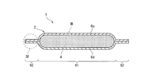
- FIG. 2 is a sectional view taken along line II-II in FIG.
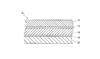
- FIG. 3 is an enlarged view of a range surrounded by a circle III in FIG. 2.
- FIG. 4 is an enlarged view of a range surrounded by a circle IV in FIG. 2.
- It is a figure which shows the measurement state of the average particle diameter of an aluminum crystal.
- It is a figure which shows the measurement state of the average particle diameter of an aluminum crystal.
- the vacuum heat insulating material 1 includes a vacuum heat insulating material packaging material 2 and a core material 4.
- the packaging material 2 for vacuum heat insulating material combines two rectangular laminates 6 (laminates for packaging material), and joins the outer peripheral portions of the combined laminates 6 to seal the outer peripheral side in a plan view. It is divided into a region 8 and a filling space forming region 10 inside the seal region 8.
- the two laminated bodies 6 forming the vacuum heat insulating material packaging material 2 are respectively arranged on the upper side in FIG. 2 and on the upper side in FIG. It may be indicated as 6d.
- the thickness of the stacked body 6 is exaggerated for the sake of explanation.
- 1st embodiment demonstrates the case where the laminated body 6 and the packaging material 2 for vacuum heat insulating materials are formed in the square by planar view as an example.
- the seal region 8 is a region for forming a seal portion 80 that thermally welds and joins the heat-welding layers 20 included in the two laminates 6 at the outer peripheral portion of the two laminates 6.
- the seal portion 80 is formed by four orthogonal straight lines surrounding the filling space forming region 10. That is, the seal part 80 is formed in a frame shape in plan view.
- the filling space forming region 10 is a portion surrounded by the seal region 8 among the two laminated bodies 6 combined, and is disposed on the inner peripheral side of the seal region 8 and is formed in a rectangular shape in plan view. .
- the filling space forming region 10 is formed in a square shape in a plan view will be described.
- the filling space forming region 10 is separated from the heat-welded layers 20 provided in the two laminates 6.
- a space formed by separating the heat-welding layers 20 provided in each of the two laminates 6 is a space in which the core material 4 can be filled in a vacuum state (hereinafter referred to as “filling space”). May be). That is, the filling space forming region 10 is a region in the filling material 2 for vacuum heat insulating material that forms a filling space.
- the filling space forming region 10 corresponds to the filling space by performing press working (molding) on at least one of the two laminated bodies 6u and 6d before heat welding the heat welding layers 20 to each other. It can be formed into a shape (such as a deep drawing shape). That is, at least one of the two laminates 6 includes a filling space forming part 61 and a seal region forming part 62. More specifically, the filling space forming part 61 is formed into a shape corresponding to the filling space by pressing, and forms a portion corresponding to the filling space forming region 10 in the laminated body 6 subjected to pressing. Yes.
- seal region forming portion 62 is a flat plate-like portion formed on the outer peripheral side of the filling space forming portion 61 and forms a portion corresponding to the seal region 8.
- press working molding
- the male mold and the female mold are closed in a state where the laminated body 6 is disposed between the male mold having the convex portion and the female mold having the concave portion, and the filling space forming region 10 in the laminated body 6 is closed.
- This is a process of deforming (stretching) the sectioned area to a shape corresponding to the filling space. Therefore, the convex part which a male type has, and the concave part which a female type have are made into the shape corresponding to filling space.
- the distance (depth of deep drawing) along the thickness direction of the stacked body 6 between the center of the filling space forming region 10 deformed by press working and the seal region 8 is as follows. The case where it is in the range of 5 mm or more and 10 mm or less will be described.
- each laminate 6 is formed in a sheet shape, and includes a protective layer 12, a first adhesive layer 14, a gas barrier layer 16, a second adhesive layer 18, and a heat welding layer 20.
- each component included in the stacked body 6u may be described with a symbol “u”.
- each component included in the stacked body 6d may be described with a symbol “d”.
- the protective layer 12 is a layer for the purpose of protecting the gas barrier layer 16 when the vacuum insulating packaging material 2 is bent, and constitutes the outermost layer of the laminate 6. The detailed configuration of the protective layer 12 will be described later.
- the first adhesive layer 14 is disposed between the protective layer 12 and the gas barrier layer 16 and adheres the protective layer 12 and the gas barrier layer 16.
- the first adhesive layer 14 is a laminating adhesive that enables dry laminating, and requires a strong laminating strength between aluminum and a polymer film. Therefore, the adhesive is preferably composed of a main agent and a curing agent. An adhesive having a polyester polyurethane bond is used. More specifically, the main agent includes, for example, an acid component containing at least two or more selected from sebacic acid, isophthalic acid, terephthalic acid, octatanic acid, nonannic acid, undecanoic acid, and palmitic acid, ethylene glycol, It is a blend of a polyester resin composed of an alcohol component containing at least one selected from hexanediol and diethylene glycol, and a bisphenol A epoxy resin.
- the curing agent is an adhesive containing a polyisocyanate component (eg, tolylene diisocyanate (TDI), diphenylmethane diisocyanate (MDI), isophorone diisocyanate (IPDI), hexamethylene diisocyanate (HDI), xylylene diisocyanate (XDI). It is an agent.
- the gas barrier layer 16 is a layer for the purpose of preventing water vapor or air from entering the filling space.
- a material for example, a film obtained by depositing a metal or an oxide on polyethylene terephthalate, an aluminum foil, or the like It is formed using the metal material which has the spreadability, and has airtightness.
- TDI tolylene diisocyanate
- MDI diphenylmethane diisocyanate
- IPDI isophorone diisocyanate
- HDI hexamethylene diisocyanate
- XDI xylylene diiso
- the thickness of the gas barrier layer 16 is 7 ⁇ m or more.
- the thickness of the gas barrier layer 16 may be in the range of 7 ⁇ m to 40 ⁇ m, preferably in the range of 9 ⁇ m to 20 ⁇ m, and more preferably in the range of 9 ⁇ m to 12 ⁇ m. This is because if the thickness of the gas barrier layer 16 is less than 7 ⁇ m, there is a high possibility that pinholes are generated in the gas barrier layer 16 when the laminate 6 is pressed, and the thickness of the gas barrier layer 16 is increased. If the thickness exceeds 40 ⁇ m, the ductility and malleability of the gas barrier layer 16 with respect to the press working will be lower than values suitable for the press working.
- the thickness of the gas barrier layer 16 is in a range of 12 ⁇ m or more and 40 ⁇ m or less.
- the material of aluminum used as the material of the gas barrier layer 16 is preferably excellent in flexibility.
- the material of the gas barrier layer 16 is, for example, in the range of 0.3% by mass or more and 9.0% by mass or less, preferably in the range of 0.7% by mass or more and 2.0% by mass or less, and more preferably.
- the aluminum alloy used as the material of the gas barrier layer 16 is preferably a soft and flexible processed product that has been annealed.
- the aluminum alloy used as the material for the gas barrier layer 16 is preferably, for example, if the average grain size of aluminum crystals is in the range of 6 ⁇ m to 12 ⁇ m and is in the range of 6 ⁇ m to 10 ⁇ m.
- the reason why the average grain size of aluminum crystals is in the range of 6 ⁇ m or more and 12 ⁇ m or less is that when the average grain size is less than 6 ⁇ m, it is difficult to adjust the annealing temperature and time of the aluminum alloy.
- the average grain size of the aluminum crystal exceeds 12 ⁇ m, the ductility and malleability of the aluminum alloy for press working are reduced from values suitable for press work.
- JIS is used as the aluminum alloy that contains iron in the range of 0.7% by mass or more and 1.7% by mass or less and the average grain size of the aluminum crystals is in the range of 6 ⁇ m or more and 12 ⁇ m or less.
- “8079” or “8021” defined in H 4160 is used.
- the average particle diameter of aluminum crystals is equal to or less than the thickness of the gas barrier layer 16 will be described.
- FIG. 5 and 6 A method for measuring the average grain size of aluminum crystals will be described with reference to FIGS. 1 to 4 and FIGS. 5 and 6.
- FIG. The average particle diameter of the aluminum crystal is a value measured by a fluorescent X-ray analyzer. Specifically, as shown in FIGS. 5 and 6, an aluminum crystal Alc is obtained in a plan view of the gas barrier layer 16 using a fluorescent X-ray analyzer with respect to an aluminum alloy foil Alf that is a sheet-like aluminum alloy. The average particle size of is measured.
- the length of “100 ⁇ m” is indicated by a bidirectional arrow as the length indicating the reference value.
- the aluminum alloy foil Alf having a small average particle diameter of the aluminum crystal Alc shown in FIG. 5 is compared with the aluminum alloy foil Alf having a large average particle diameter of the aluminum crystal Alc shown in FIG. Is small. For this reason, the aluminum alloy foil Alf having a small average particle size has a gap in which the aluminum crystal Alc moves during press working, that is, when the aluminum alloy foil is extended, as compared with the aluminum alloy foil Alf having a large average particle size. Since it is wide, ductility and malleability with respect to press working are increased.
- the second adhesive layer 18 is disposed between the gas barrier layer 16 and the heat welding layer 20 and adheres the gas barrier layer 16 and the heat welding layer 20. Further, the second adhesive layer 18 is a laminating adhesive that enables dry laminating processing similarly to the first adhesive layer 14, and preferably requires a strong laminating strength between aluminum and a polymer film.
- the adhesive consists of a main agent and a curing agent, and an adhesive having a polyester polyurethane bond is used. More specifically, the main agent and the curing agent may be the same as the main agent and the curing agent of the laminate adhesive constituting the first adhesive layer 14.
- the main component of the laminating adhesive constituting the second adhesive layer 18 is, for example, at least two or more selected from sebacic acid, isophthalic acid, terephthalic acid, octatanic acid, nonannic acid, undecanoic acid, and palmitic acid.
- the curing agent of the laminate adhesive constituting the second adhesive layer 18 is a polyisocyanate component (for example, tolylene diisocyanate (TDI), diphenylmethane diisocyanate (MDI), isophorone diisocyanate (IPDI), hexamethylene diisocyanate (HDI), An adhesive containing xylylene diisocyanate (XDI).
- TDI tolylene diisocyanate
- MDI diphenylmethane diisocyanate
- IPDI isophorone diisocyanate
- HDI hexamethylene diisocyanate
- XDI An adhesive containing xylylene diisocyanate
- the heat welding layer 20 is a layer for sealing the core material 4 filled in the filling space in a vacuum state by forming the seal region 8, and has a material capable of heat welding, for example, thermoplasticity. It is formed using a polyolefin polymer material. Further, the heat-welded layer 20u included in the stacked body 6u is a heat-welded layer in which the surface opposite to the surface facing the second adhesive layer 18 is combined with the two stacked bodies 6u and 6d. In surface contact with layer 20d. In the first embodiment, as an example, a case where the material of the heat welding layer 20 is a polyolefin polymer material will be described. Moreover, the material which can be heat-welded which forms the heat-welding layer 20 uses, for example, a resin containing cast polypropylene when heat resistance of 100 ° C. or higher is required as the use condition of the vacuum heat insulating material 1.
- the thickness of the heat-welded layer 20 is in the range of 10 ⁇ m to 100 ⁇ m, and the melting point of the resin is 70 ° C. The above is preferred. This is because if the thickness of the heat-welded layer 20 is less than 10 ⁇ m, the heat seal strength in heat-welding is insufficient, so that cracks are easily generated with respect to impact.
- the core material 4 is formed using, for example, a material having fine voids such as glass wool, foamed polyurethane, and silica powder, and is filled in the filling space in a vacuum state.
- the protective layer 12 is formed using a stretched nylon film as a material.
- a stretched nylon film for example, a nylon film having a polyamide resin as a basic skeleton is used.
- the nylon film having a polyamide resin as a basic skeleton includes, for example, nylon 6, nylon 66, a copolymer of nylon 6 and nylon 66, metaxylylene adipamide (MXD6), and the like.
- the stretched nylon film which is the material of the protective layer 12 is manufactured by simultaneous biaxial stretching.
- the simultaneous biaxial stretching process is performed by stretching the film simultaneously in the film flow direction (MD direction) and in the vertical direction (TD direction) perpendicular to the film flow direction when the film is stretched. It is the processing method to manufacture.
- the stretched nylon film passes through one preset point, extends radially along the surface of the protective layer 12, and has four imaginary lines (virtual lines) having an interval of 45 ° between adjacent lines.
- Each stretch strength in the direction along the straight line) was 100 N / mm 2 or more, and the stretched nylon film had an elongation percentage in the direction along the phantom line of 80% or more.
- the measuring method of the breaking strength (tensile strength) of the above-mentioned stretched nylon film will be described later.
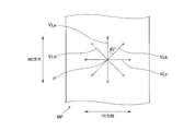
- it passes along the width direction center P of the material film MF which is one point preset, and it extends radially along the surface of the protective layer 12, and is adjacent.
- Four imaginary lines VL that are 45 ° apart from the line pass through the center P in the width direction of the material film MF, and the four directions (0 ° direction, 45 degrees, 90 degrees, and 135 degrees directions).
- the material film MF is a stretched nylon film before the protective layer 12 is formed. Further, the center P in the width direction of the material film MF is set to an area of the laminate 6 that is partitioned into the filling space forming area 10.
- virtual lines VL in four directions are represented by a virtual line VLa in the 0 ° direction with respect to the MD direction, and a virtual line VLb in the 45 ° direction in the clockwise direction with reference to the MD direction.
- one of the four imaginary lines (VLa to VLd) (the imaginary line VLa) is, in plan view, the conveyance direction (MD direction) at the time of manufacturing the stretched nylon film.
- the thickness of the protective layer 12 is at least 6 ⁇ m or more.
- the thickness of the protective layer 12 is in the range of 9 ⁇ m to 50 ⁇ m. This is because if the thickness of the protective layer 12 is less than 9 ⁇ m, the stretched nylon film has insufficient elongation performance, and the gas barrier layer 16 is necked and broken when the vacuum heat insulating packaging material 2 is bent. Because.
- the breaking strength of the stretched nylon film was measured in accordance with JIS K7127 under the conditions of a test piece of 15 mm, a chuck interval of 50 mm, and a test speed of 200 mm / min.
- the manufacturing method of the vacuum heat insulating material 1 has a laminated body press process, the bag body production process which is a post process of a laminated body press process, and the vacuum filling process which is a post process of a bag body production process.
- Laminate pressing step In the laminate pressing step, at least one of the two laminates 6u, 6d is pressed (molded) between the male die and the female die to form a filling space.
- the formation region 10 has a shape (such as a deep drawing shape) corresponding to the filling space.
- a process of clearly partitioning the shape of the portion constituting the seal region 8 and the shape of the portion constituting the filling space forming region 10 is performed on the two stacked bodies 6u and 6d.
- a process of clearly partitioning the shape of the portion (filling space forming portion 61) constituting the region 10 is performed. Further, by pressing the laminate 6, an edge (edge) that is continuous in a frame shape in a plan view is formed in a portion constituting the filling space forming region 10 in the laminate 6 to be pressed. .
- Bag body production process In the bag body production process, the two laminated bodies 6u and 6d are overlapped in a matched state, and the thermal welding layers 20 included in each of the three outer sides are opposed to each other. First heat welding is performed. As a result, the heat-welded layers 20 are joined together to form a portion composed of three orthogonal straight lines in the seal portion 80 formed of four orthogonal straight lines surrounding the filling space forming region 10. Then, a bag body in which the other side of the outer peripheral portion is opened is created.
- the core material 4 is inserted into the space formed between the two laminated bodies 6u and 6d from the opening formed in the bag body creation process, and the core material 4 is further inserted.
- the pressure in the space is reduced to 200 Pa or less, heat welding is performed on the remaining one side that has not been heat-welded in the bag forming process.
- the filling space forming region 10 the filling space, and the frame-shaped seal portion 80 are formed, and the core material 4 is filled in the filling space in a vacuum state.
- the protective layer 12 included in the laminated body 6 extends radially along the surface of the protective layer 12 through the center P in the width direction of the material film MF, which is a preset point
- each layer is formed of a stretched nylon film having a breaking strength of 100 N / mm 2 or more in a direction along four virtual lines (VLa to VLd) having an interval of 45 ° between adjacent lines.
- VLa to VLd virtual lines
- the nylon film makes it possible to form the protective layer 12 having a high breaking strength.
- a representative breaking strength of the eight directions extending radially, as 100 N / mm 2 or more, the breaking strength of the entire protective layer 12, and can be a 100 N / mm 2 or more Become.
- the vacuum heat insulating material 1 As a result, it is possible to improve the rigidity and bending resistance of the vacuum heat insulating packaging material 2, and it is possible to suppress a decrease in the rigidity and bending resistance of the protective layer 12 due to moisture absorption.
- the gas barrier It becomes possible to suppress the occurrence of damage such as cracks in the layer 16. With such a laminate for packaging material, it becomes possible to prevent the occurrence of pinholes and cracks during the formation of the packaging material for vacuum insulation material, and the reduced pressure environment (high vacuum state) in the manufactured vacuum insulation material ) Can be held. Therefore, if it is the laminated body 6 for packaging materials which concerns on 1st embodiment, the vacuum heat insulating material 1 provided with sufficient heat insulation performance can be provided.
- VLa imaginary line
- MD direction transport direction
- the stretched nylon film forming the protective layer 12 is a film having an elongation rate in the direction along the imaginary line VL of 80% or more. For this reason, in the protective layer 12, it is possible to set the elongation rate in the representative eight directions extending radially to 80% or more and the overall elongation rate of the protective layer 12 to 80% or more.
- the thickness of the protective layer 12 is in the range of 9 ⁇ m to 50 ⁇ m. For this reason, it becomes possible to form the highly durable protective layer 12 with only one layer of stretched nylon film.
- the stretched nylon film forming the protective layer 12 is manufactured by simultaneous biaxial stretching. For this reason, it becomes possible to simplify the manufacturing process of the laminated body 6 compared with the case where a stretched nylon film is manufactured by sequential biaxial stretching, and the manufacturing process of the packaging material 2 for vacuum heat insulating materials is simplified. It becomes possible.
- the filling space forming region 10 is formed by pressing the stacked body 6. For this reason, it becomes possible to manufacture the packaging material 2 for vacuum heat insulating materials by the continuous process with respect to the laminated body 6 conveyed.
- the vacuum heat insulating material 1 passes through the center P in the width direction of the material film MF, which is one point set in advance, and extends radially along the surface of the protective layer 12, and the distance between adjacent lines is 45 °.
- the laminate 6 (laminate for packaging material) has rigidity, bending resistance, and high breaking strength
- the laminate 6 (laminate for packaging material) is press-molded (pressing and molding). Even if it is a case where it uses and is used for the packaging material 2 for vacuum heat insulating materials, it becomes possible to suppress generation
- the gas barrier layer 16 is formed of an aluminum alloy having an average particle diameter of aluminum crystals in the range of 6 ⁇ m to 12 ⁇ m and containing iron in the range of 0.7 mass% to 1.7 mass%. May be. In this case, it becomes possible to increase the ductility and malleability of the aluminum alloy with respect to the press work, suppress the damage of the gas barrier layer 16 due to the press work, and form the filling space formed by the press work on the laminate 6. It becomes possible to improve the freedom degree of the shape of the part 61.
- the vacuum that can correspond to the shape of the vacuum heat insulating material 1 It becomes possible to form the packaging material 2 for heat insulating materials.
- the ductility and malleability of the gas barrier layer 16 can be increased, even if the gas barrier layer 16 is stretched when the seal region 8 is bent, generation of pinholes in the gas barrier layer 16 is prevented. It becomes possible to suppress.
- the thickness of the gas barrier layer 16 may be in the range of 9 ⁇ m to 20 ⁇ m. In this case, compared with the case where the thickness of the gas barrier layer 16 is less than 9 ⁇ m, the possibility that pinholes are generated in the gas barrier layer 16 when the laminate 6 is pressed is reduced. It becomes possible. In addition to this, it is possible to reduce the thermal conductivity of the laminated body 6 and to improve the heat insulating performance of the vacuum heat insulating material 1 as compared with the case where the thickness of the gas barrier layer 16 exceeds 20 ⁇ m. .
- the average grain size of the aluminum crystals contained in the aluminum alloy forming the gas barrier layer 16 may be 10 ⁇ m or less. In this case, it becomes possible to increase the ductility and malleability of the aluminum alloy with respect to press working, compared to the case where the average grain size of the aluminum crystal contained in the aluminum alloy exceeds 10 ⁇ m. As a result, damage to the gas barrier layer 16 due to press working can be suppressed, so that the degree of freedom of the shape of the filling space forming region 10 formed by press working on the stacked body 6 can be improved. .
- the average particle diameter of the aluminum crystal contained in the aluminum alloy forming the gas barrier layer 16 may be a value measured by fluorescent X-ray diffraction with respect to the aluminum alloy in a plan view of the gas barrier layer 16. In this case, the average particle diameter of the aluminum crystal contained in the aluminum alloy is measured by fluorescent X-ray diffraction before the laminated body 6 is manufactured, and the physical properties of the aluminum alloy are appropriate as the material of the gas barrier layer 16. It is possible to determine whether or not there is.
- the vacuum heat insulating material 1 includes the vacuum heat insulating packaging material 2 including the filling space forming portion 61 formed by pressing the laminated body 6 including the gas barrier layer 16 formed of an aluminum alloy, and in a vacuum state. You may provide the core material 4 with which filling space is filled.
- the gas barrier layer 16 is made of an aluminum alloy having an average grain size of aluminum crystals in the range of 6 ⁇ m to 12 ⁇ m and containing iron in the range of 0.7 mass% to 1.7 mass%. It may be formed.
- the degree of freedom of the shape of the filling space forming portion 61 is different even when the requirements for the shape of the vacuum heat insulating material 1 differ depending on the use such as for home appliances, equipment, and buildings. It becomes possible to form the vacuum heat insulating material 1 of the shape according to a use using the packaging material 2 for vacuum heat insulating materials with high.
- the stretched nylon film forming the protective layer 12 passes through a preset point and extends radially along the surface of the protective layer 12 and has an interval of 45 ° between adjacent lines.
- the stretched nylon film has a breaking strength of 100 N / mm 2 or more in the direction along the four imaginary lines VL, but is not limited thereto. That is, for example, as shown in FIG. 8, the stretched nylon film that forms the protective layer 12 passes through the center P in the width direction of the material film MF, which is a preset point, and is transported during production in a plan view.
- the stretched nylon film may have a breaking strength of 100 N / mm 2 or more in the direction along two virtual lines VL inclined by 45 ° from the direction (MD direction).
- the filling space forming region 10 of the filling space forming region 10 is folded when the vacuum heat insulating material packaging material 2 is bent.
- High rigidity can be exhibited with respect to the stress generated at the corner, that is, higher than the stress generated at other portions. For this reason, it becomes possible to improve the rigidity of the packaging material 2 for vacuum heat insulating materials.
- VLMD a virtual line indicating the MD direction
- VLMD a virtual line VL inclined 45 ° clockwise (clockwise) from the MD direction
- VL2 a virtual line VL indicated by “VL1” and inclined by 45 ° counterclockwise (counterclockwise) from the MD direction
- the stretched nylon film that forms the protective layer 12 passes through a preset point, extends radially along the surface of the protective layer 12, and is an imaginary line that overlaps the diagonal line of the filling space forming region 10 in plan view. It is good also as a stretched nylon film whose each breaking strength of the direction along is 100 N / mm ⁇ 2 > or more.
- the present invention is not limited to this. That is, press working may be performed on only one of the two laminated bodies 6u and 6d. In this case, rigidity is required for the laminate 6 to be pressed.
- the laminated body 6 to be pressed is the laminated body 6 of the first embodiment, that is, the protective layer 12 passes through the center P in the width direction of the material film MF, which is one point set in advance.
- the laminated body 6 on the side not subjected to press working only needs to include the protective layer 12, the gas barrier layer 16, and the heat welding layer 20 having a configuration different from that of the first embodiment.
- the two laminated bodies 6u and 6d are both protected by the laminated body 6 of the first embodiment, that is, the protective layer 12 passes through the center P in the width direction of the material film MF, which is a preset point.
- Each layer is formed of a stretched nylon film having a breaking strength of 100 N / mm 2 or more in a direction along four imaginary lines extending radially along the surface of the layer 12 and having an interval of 45 ° between adjacent lines. It is preferable to use the laminated body 6.
- the thickness of the gas barrier layer 16 is in the range of 9 ⁇ m to 20 ⁇ m, but is not limited thereto. That is, the upper limit value of the thickness of the gas barrier layer 16 may be 12 ⁇ m. In this case, compared to the case where the upper limit value of the thickness of the gas barrier layer 16 exceeds 12 ⁇ m, the thermal conductivity of the laminate 6 can be reduced, and the heat insulating performance of the vacuum heat insulating material 1 can be improved. It becomes.
- the present invention is not limited to this. That is, the aluminum alloy forming the gas barrier layer 16 contains iron within the range of 0.7% by mass or more and 1.7% by mass or less, and the average grain size of the aluminum crystals is within the range of 6 ⁇ m or more and 12 ⁇ m or less.
- the alloy is not limited to “8079” or “8021” defined in JIS H 4160.
- FIG. 9 will be used to explain the vacuum heat insulating material 1 of the present invention example and the comparative example according to examples described below.
- the vacuum heat insulating material 1 of the example has the same structure as the first embodiment described above, the protective layer 12, the first adhesive layer 14, the gas barrier layer 16, the second adhesive layer 18, the thermal welding layer 20, Each layer is formed by laminating by dry laminating. Moreover, the specific structure of each layer except the protective layer 12 shall be shown below.
- First adhesive layer 14 A polyester polyurethane adhesive (LX500 manufactured by DIC) is used as a main agent, and an aromatic isocyanate (KW75 manufactured by DIC) is used as a curing agent.
- -Gas barrier layer 16 The aluminum alloy (8021 by Toyo Aluminum Co., Ltd.) prescribed
- Second adhesive layer 18 A polyester polyurethane adhesive (LX500 manufactured by DIC) is used as a main agent, and an aromatic isocyanate (KW75 manufactured by DIC) is used as a curing agent.
- -Thermal welding layer 20 Low density linear polyethylene (LLDPE: TUX-FCS manufactured by Mitsui Chemicals, Inc.) manufactured by casting is used as a material.
- Example 1 The vacuum heat insulating material 1 of Example 1 of the present invention was manufactured by an inflation method as a material of the protective layer 12 and had a thickness of 25 ⁇ m and passed through a preset point indicated as “stretched nylon 1” in Table 1. Then, the breaking strength in the direction along the four virtual lines VL extending radially along the surface of the protective layer 12 and having an interval of 45 ° between the adjacent lines, and the direction along the virtual line VL A stretched nylon film having an elongation rate is used.
- the vacuum heat insulating material 1 of Example 1 of the present invention has a thickness of 12 ⁇ m as a material of the gas barrier layer 16 and contains 1.0 mass% of iron, and the average particle diameter of the aluminum crystal Alc is 10 ⁇ m.
- the aluminum alloy is used.
- the direction of the virtual line VL is the same as that in the first embodiment.
- the aluminum alloy is also referred to as “aluminum alloy 1”.
- “1” of the AL type shown in Table 2 refers to the aluminum alloy.
- “0 °” shown in Table 1 indicates the direction along the imaginary line VLa in FIG. 7, and “45 °” shown in Table 1 indicates the direction along the imaginary line VLb in FIG. Show. Further, “90 °” shown in Table 1 indicates the direction along the virtual line VLc in FIG. 7, and “135 °” shown in Table 1 indicates the direction along the virtual line VLd in FIG. Show.
- Example 2 The vacuum heat insulating material 1 of Example 2 of the present invention was manufactured by an inflation method as a material of the protective layer 12 and had a thickness of 25 ⁇ m and passed through a preset point indicated as “stretched nylon 1” in Table 1. Then, the breaking strength in the direction along the four virtual lines VL extending radially along the surface of the protective layer 12 and having an interval of 45 ° between the adjacent lines, and the direction along the virtual line VL A stretched nylon film having an elongation rate is used.
- the vacuum heat insulating material 1 of Example 2 of the present invention has a thickness of 20 ⁇ m as a material of the gas barrier layer 16 and contains 1.0% by mass of iron, and the average particle diameter of the aluminum crystal Alc is 10 ⁇ m.
- An aluminum alloy (aluminum alloy 1) is used.
- the direction of the virtual line VL is the same as that in the first embodiment.
- the vacuum heat insulating material 1 of Example 3 of the present invention was manufactured by an inflation method as a material for the protective layer 12 and had a thickness of 25 ⁇ m and passed through a preset point indicated as “stretched nylon 1” in Table 1. Then, the breaking strength in the direction along the four virtual lines VL extending radially along the surface of the protective layer 12 and having an interval of 45 ° between the adjacent lines, and the direction along the virtual line VL A stretched nylon film having an elongation rate is used.
- the vacuum heat insulating material 1 of Example 3 of the present invention is an aluminum alloy having a thickness of 20 ⁇ m and a very low iron content (for example, less than 0.1% by mass) as a material of the gas barrier layer 16.
- the aluminum alloy is also referred to as “aluminum alloy 2”. Further, “2” of the AL type shown in Table 2 refers to the aluminum alloy.
- Example 4 The vacuum heat insulating material 1 of Example 4 of the present invention was manufactured by an inflation method as a material of the protective layer 12 and had a thickness of 15 ⁇ m and passed through a preset point indicated as “stretched nylon 2” in Table 1. Then, the breaking strength in the direction along the four virtual lines VL extending radially along the surface of the protective layer 12 and having an interval of 45 ° between the adjacent lines, and the direction along the virtual line VL A stretched nylon film having an elongation rate is used.
- the vacuum heat insulating material 1 of Example 4 of the present invention has a thickness of 20 ⁇ m as a material of the gas barrier layer 16 and contains 1.0% by mass of iron, and the average particle diameter of the aluminum crystal Alc is 10 ⁇ m.
- An aluminum alloy (aluminum alloy 1) is used.
- the direction of the virtual line VL is the same as that in the first embodiment.
- the vacuum heat insulating material 1 of the invention example 5 is manufactured by an inflation method as a material of the protective layer 12 and has a thickness of 15 ⁇ m, and passes a preset one point indicated as “stretched nylon 2” in Table 1. Then, the breaking strength in the direction along the four virtual lines VL extending radially along the surface of the protective layer 12 and having an interval of 45 ° between the adjacent lines, and the direction along the virtual line VL A stretched nylon film having an elongation rate is used.
- the vacuum heat insulating material 1 of Example 5 of the present invention is an aluminum alloy having a thickness of 40 ⁇ m and a very low iron content (for example, less than 0.1% by mass) as a material of the gas barrier layer 16. (For example, 1N30 defined in JIS H 4160) (aluminum alloy 2) is used.
- the direction of the virtual line VL is the same as that in the first embodiment.
- the vacuum heat insulating material 1 of Example 6 of the present invention was manufactured by an inflation method as a material of the protective layer 12 and had a thickness of 15 ⁇ m and passed through a preset point indicated as “stretched nylon 2” in Table 1. Then, the breaking strength in the direction along the four virtual lines VL extending radially along the surface of the protective layer 12 and having an interval of 45 ° between the adjacent lines, and the direction along the virtual line VL A stretched nylon film having an elongation rate is used.
- the vacuum heat insulating material 1 of Example 6 of the present invention is an aluminum alloy having a thickness of 20 ⁇ m and a very low iron content (for example, less than 0.1% by mass) as a material of the gas barrier layer 16. (For example, 1N30 defined in JIS H 4160) (aluminum alloy 2) is used.
- the direction of the virtual line VL is the same as that in the first embodiment.
- Example 7 The vacuum heat insulating material 1 of Example 7 of the present invention was manufactured by an inflation method as a material of the protective layer 12 and had a thickness of 15 ⁇ m and passed through a preset point indicated as “stretched nylon 2” in Table 1. Then, the breaking strength in the direction along the four virtual lines VL extending radially along the surface of the protective layer 12 and having an interval of 45 ° between the adjacent lines, and the direction along the virtual line VL A stretched nylon film having an elongation rate is used.
- the vacuum heat insulating material 1 of Example 7 of the present invention has a thickness of 12 ⁇ m as a material of the gas barrier layer 16 and contains 1.0 mass% of iron, and the average particle diameter of the aluminum crystal Alc is 10 ⁇ m.
- An aluminum alloy (aluminum alloy 1) is used.
- the direction of the virtual line VL is the same as that in the first embodiment.
- the vacuum heat insulating material 1 of Example 8 of the present invention was manufactured by an inflation method as a material for the protective layer 12 and had a thickness of 15 ⁇ m and passed through a preset point indicated as “stretched nylon 2” in Table 1. Then, the breaking strength in the direction along the four virtual lines VL extending radially along the surface of the protective layer 12 and having an interval of 45 ° between the adjacent lines, and the direction along the virtual line VL A stretched nylon film having an elongation rate is used.
- the vacuum heat insulating material 1 of Example 8 of the present invention is an aluminum alloy having a thickness of 12 ⁇ m and a very low iron content (for example, less than 0.1% by mass) as a material of the gas barrier layer 16. (For example, 1N30 defined in JIS H 4160) (aluminum alloy 2) is used.
- the direction of the virtual line VL is the same as that in the first embodiment.
- the vacuum heat insulating material 1 of the comparative example 1 was manufactured by a casting method as a material of the protective layer 12 and had a thickness of 15 ⁇ m, and passed a preset one point indicated as “stretched nylon 3” in Table 1.
- the rupture strength in the direction along the four imaginary lines VL extending radially along the surface of the protective layer 12 and having an interval of 45 ° between adjacent lines, and the extension in the direction along the imaginary line VL A stretched nylon film having a rate is used.
- the vacuum heat insulating material 1 of Comparative Example 1 is an aluminum alloy (as a material for the gas barrier layer 16) having a thickness of 20 ⁇ m and a very low iron content (for example, less than 0.1% by mass) (for example, 1N30) (aluminum alloy 2) defined in JIS H 4160 is used.
- the direction of the virtual line VL is the same as that in the first embodiment.
- the vacuum heat insulating material 1 of Comparative Example 2 was manufactured by a casting method as a material for the protective layer 12 and had a thickness of 15 ⁇ m, and passed a preset one point indicated as “stretched nylon 3” in Table 1.
- the rupture strength in the direction along the four imaginary lines VL extending radially along the surface of the protective layer 12 and having an interval of 45 ° between adjacent lines, and the extension in the direction along the imaginary line VL A stretched nylon film having a rate is used.
- the vacuum heat insulating material 1 of Comparative Example 2 has a thickness of 40 ⁇ m as a material of the gas barrier layer 16, contains 1.0 mass% of iron, and has an average particle diameter of aluminum crystal Alc of 10 ⁇ m.
- An aluminum alloy (aluminum alloy 1) is used.
- the direction of the virtual line VL is the same as that in the first embodiment.
- Comparative Example 3 The vacuum heat insulating material 1 of Comparative Example 3 was manufactured by a casting method as a material of the protective layer 12 and had a thickness of 15 ⁇ m, and passed a preset one point indicated as “stretched nylon 3” in Table 1. The rupture strength in the direction along the four imaginary lines VL extending radially along the surface of the protective layer 12 and having an interval of 45 ° between adjacent lines, and the extension in the direction along the imaginary line VL A stretched nylon film having a rate is used.
- the vacuum heat insulating material 1 of Comparative Example 3 is an aluminum alloy having a thickness of 40 ⁇ m and a very low iron content (for example, less than 0.1% by mass) as a material of the gas barrier layer 16 (for example, 1N30) (aluminum alloy 2) defined in JIS H 4160 is used.
- the direction of the virtual line VL is the same as that in the first embodiment.
- the maximum deep drawing distance 1 indicates the maximum deep drawing distance when measured without applying a lubricant (erucic acid amide) to the surface of the vacuum heat insulating material 1.
- the “state during 6 mm deep drawing” indicates a pinhole situation when 6 mm deep drawing is performed without applying a lubricant to the surface of the vacuum heat insulating material 1.
- “Maximum deep drawing distance 2” indicates the maximum deep drawing distance when a lubricant (erucamide) is applied and measured in order to make the friction coefficient of the surface of the vacuum heat insulating material 1 uniform between samples. Is. The results of each measurement are shown in Table 2. In Table 2, items indicated by “ ⁇ ” and blanks indicate that measurement was impossible or measurement was impossible. Further, Comparative Example 1 in Table 2 corresponds to the difference in the type of nylon of Example 3. Comparative Example 3 corresponds to the difference in the type of nylon of Example 5.
- the deep drawability of the laminate 6 was measured using a deep draw verifying machine 22 shown in FIG.
- the deep drawing verifying machine 22 includes a male mold 24, a female mold 26, and a stripper plate 28.
- the male mold 24 includes a convex portion 30 that protrudes downward toward the female mold 26.
- the female die 26 is arranged below the male die 24, and a convex arrangement space 32 in which the convex part 30 can be arranged is formed.
- the stripper plate 28 is a plate-like member for pressing the laminated body 6 against the flat portion 34 in which the convex arrangement space 32 is not formed in the female die 26, and is movable in the vertical direction.
- the male die 24 and the female die 26 are opened with the male die 24 and the female die 26 opened (die opening state).
- the laminate 6 disposed between the two is pressed against the flat portion 34 by the stripper plate 28 and fixed.
- the distance between the male mold 24 and the female mold 26 is decreased, and the stacked body 6 is pushed (pressed) downward by the convex portion 30, and further, the downward moving distance of the convex portion 30 in the convex portion arrangement space 32. (Deep drawing distance) is changed, and an average distance until a pinhole is generated in the gas barrier layer 16 is calculated.
- the deep drawing distance (mm) shown in Table 2 is calculated from the average distance until pinholes are generated in the gas barrier layer 16.
- this deep drawing distance is determined when the lubricant is not applied to the surface of the vacuum heat insulating material 1 (maximum deep drawing distance 1) and when the lubricant is applied to the surface of the vacuum heat insulating material 1 (maximum depth). The measurement was performed separately for the aperture distance 2).
- erucic acid amide was used as the lubricant.
- positioning space 32 shall be 1 mm, and the hard type
- the change speed of the deep drawing distance (that is, the deep drawing speed) was constant (10 mm / min).
- the holding time of the laminated body 6 was 2 seconds, and the pressing pressure of the laminated body 6 was 0.8 MPa.
- the laminate 6 was heated periodically, and the thermal conductivity of the laminate 6 was measured using an AC heating method in which the response of heat according to the frequency and the amplitude at the distance from the measurement location was measured.
- a phenomenon that heat is conducted through the film a phenomenon called a thermal bridge
- Table 2 it can be seen that Examples 1 to 6 of the present invention have a larger maximum deep drawing distance than Comparative Examples 1 and 2. It can also be seen that the maximum deep drawing distance is similarly increased by increasing the thickness of the aluminum foil as the gas barrier layer 16. However, when the thickness of the aluminum foil is increased by the gas barrier layer 16, the value of the thermal conductivity increases, which is not desirable.
- the packaging material for vacuum heat insulating materials As mentioned above, if it is the laminated body for packaging materials which concerns on 1st embodiment, the packaging material for vacuum heat insulating materials, and a vacuum heat insulating material, the subject which this invention will solve can be solved.
- peripheral technologies and related technologies of the invention according to the first embodiment of the present invention will be described.
- a vacuum heat insulating material As a heat insulating material having excellent heat insulating performance, a vacuum heat insulating material is provided with a packaging material for vacuum heat insulating material formed by combining two laminates having gas tightness (gas barrier properties) and a core material having fine voids. There is a vacuum heat insulating material formed by vacuum filling a core material inside the packaging material.
- the vacuum heat insulating material exhibits high heat insulating performance by maintaining the inside of the vacuum heat insulating packaging material at a high degree of vacuum and suppressing heat transfer due to gas convection. For this reason, the packaging material for vacuum heat insulating materials is required to have high gas barrier properties.
- the core material such as glass wool into the vacuum insulating material packaging material
- it is filled by applying pressure from above in the vacuum chamber.
- glass wool is a material obtained by processing glass into a fiber shape of 10 ⁇ m or less.
- the core material may break through the laminate from the inside. For this reason, rigidity is requested
- Patent Document 1 includes a configuration in which two or more layers of nylon films having excellent mechanical properties such as rigidity and bending resistance are laminated to improve rigidity and bending resistance. It is disclosed.
- SYMBOLS 1 Vacuum heat insulating material, 2 ... Packaging material (packaging material for vacuum heat insulating material), 4 ... Core material, 6 ... Laminated body (laminated body for packaging material), 8 ... Sealing area, 10 ... Filling space formation area, 12 ... Protective layer, 14 ... first adhesive layer, 16 ... gas barrier layer, 18 ... second adhesive layer, 20 ... thermal weld layer, 22 ... deep drawing verifier, 24 ... male type, 26 ... female type, 28 ... stripper plate, DESCRIPTION OF SYMBOLS 30 ... Convex part, 32 ... Convex part arrangement space, 34 ... Plane part, 61 ... Filling space formation part, 62 ... Seal area formation part, 80 ... Seal part, VL ... Virtual line, MF ... Material film, P ... Material film Center of width direction of MF, Alf ... aluminum alloy foil, Alc ... aluminum crystal
Landscapes
- Engineering & Computer Science (AREA)
- General Engineering & Computer Science (AREA)
- Mechanical Engineering (AREA)
- Thermal Insulation (AREA)
- Wrappers (AREA)
- Laminated Bodies (AREA)
Abstract
剛性及び耐屈曲性を向上させることが可能な包装材用積層体、包装材用積層体で形成した真空断熱材用包装材、真空断熱材用包装材を備えた真空断熱材を提供する。本発明に係る包装材用積層体は、熱溶着層とガスバリア層と保護層とを順に積層した二枚の包装材用積層体の外周部を熱溶着で接合し、真空状態で芯材を充填可能な充填空間が内部に形成される真空断熱材用包装材を形成する包装材用積層体であって、保護層は、予め設定した一点である材料フィルム(MF)の幅方向中心(P)を通過して保護層の面に沿って放射状に延び、且つ隣り合う線との間隔が45°である四本の仮想線(VL)に沿った方向の各破断強度が100N/mm2以上の延伸ナイロンフィルムで形成されている包装材用積層体である。
Description
本発明は、包装材用積層体、真空断熱材用包装材及び真空断熱材に関する。
真空断熱材形成用の真空断熱材用包装材を形成する包装材用積層体には、例えば、特許文献1、2に記載された積層体がある。そして、この特許文献1には、剛性や耐屈曲性等の機械的特性に優れたナイロンフィルムを、二層以上積層した構成として、剛性及び耐屈曲性を向上させた構成が開示されている。
また、上記包装材用積層体と構成は略同じであるが使用目的が異なる包装材用積層体として、リチウムイオン電池の包装材を形成する包装材用積層体(以下、単に「Li電池包装材用積層体」ともいう。)がある。このLi電池包装材用積層体の構成は、例えば、特許文献3、4に記載されている。そして、この特許文献3、4には、当該特許文献に記載のLi電池包装材用積層体であれば、Li電池の包装材の成形時におけるピンホールやクラックの発生を防止可能である旨が開示されている。
また、上記包装材用積層体と構成は略同じであるが使用目的が異なる包装材用積層体として、リチウムイオン電池の包装材を形成する包装材用積層体(以下、単に「Li電池包装材用積層体」ともいう。)がある。このLi電池包装材用積層体の構成は、例えば、特許文献3、4に記載されている。そして、この特許文献3、4には、当該特許文献に記載のLi電池包装材用積層体であれば、Li電池の包装材の成形時におけるピンホールやクラックの発生を防止可能である旨が開示されている。
上記包装材用積層体を構成するナイロンフィルムは、一般に吸湿性が高い。このため、従来技術に係る包装材用積層体は、特許文献1に開示されている構成のように、二層以上のナイロンフィルムを積層すると、その剛性及び耐屈曲性が早期に低下して包装材を形成する際にピンホールやクラックが発生することがある。このため、上記包装材用積層体を用いて製造した真空断熱材には、十分な断熱性能が得られないものがあるという課題がある。
ここで、特許文献3、4に記載されたLi電池包装材用積層体を用いて、真空断熱材用包装材を形成した場合を想定する。その場合には、真空断熱材用包装材を形成する際に、真空断熱材用包装材にピンホールやクラックが発生し、製造した真空断熱材内の減圧環境(高真空状態)を保持できない可能性がある。その結果、上記Li電池包装材用積層体を用いて製造した真空断熱材は、十分な断熱性能が得られない可能性がある。以下、この点について、より詳しく説明する。
ここで、特許文献3、4に記載されたLi電池包装材用積層体を用いて、真空断熱材用包装材を形成した場合を想定する。その場合には、真空断熱材用包装材を形成する際に、真空断熱材用包装材にピンホールやクラックが発生し、製造した真空断熱材内の減圧環境(高真空状態)を保持できない可能性がある。その結果、上記Li電池包装材用積層体を用いて製造した真空断熱材は、十分な断熱性能が得られない可能性がある。以下、この点について、より詳しく説明する。
一般に、Li電池内は、大気圧(常圧)または上記真空断熱材内の圧力に比べて低圧となっている。このため、Li電池包装材用積層体に要求される、包装材の形成時におけるピンホールやクラックの発生を防止する機能(以下、単に「ピンホール防止能」ともいう。)は、大気圧環境下にあるLi電池内に酸素や水分の侵入を阻止可能であれば十分である。これに対し、真空断熱材用包装材を形成する包装材用積層体に要求されるピンホール防止能は、製造した真空断熱材内の減圧環境(高真空状態)を保持する必要があるために、従来技術に係るLi電池包装材用積層体が備えるピンホール防止能に比べて高い。換言すると、真空断熱材用包装材を形成するための包装材用積層体には、従来技術に係るLi電池包装材用積層体よりも、さらに微小なピンホールや微細なクラックの発生を防止する機能が要求される。このため、特許文献3、4に記載された、ピンホール防止能が低いLi電池包装材用積層体を用いて真空断熱材用包装材を形成した場合には、真空断熱材内の減圧環境(高真空状態)を保持できず、十分な断熱性能を備えない真空断熱材が製造される可能性がある。
本発明は、このような問題点を解決しようとするものであり、剛性及び耐屈曲性を向上させることが可能な包装材用積層体と、その包装材用積層体で形成した真空断熱材用包装材と、その真空断熱材用包装材を備えた真空断熱材を提供することを目的とする。より詳しくは、剛性及び耐屈曲性を向上させることで真空断熱材用包装材の形成時におけるピンホールやクラックの発生を防止可能とし、真空断熱材内の減圧環境下(高真空状態)を保持可能な包装材用積層体と、その包装材用積層体で形成した真空断熱材用包装材と、その真空断熱材用包装材を備えた真空断熱材を提供することを目的とする。
上記の目的を達成するために、本発明の一態様は、組み合わせた二枚の外周部同士を熱溶着で接合し、真空状態で芯材を充填可能な充填空間が内部に形成される真空断熱材用包装材を形成する包装材用積層体であって、
熱溶着層とガスバリア層と保護層とを順に積層して形成され、
前記保護層は、予め設定した一点を通過して前記保護層の面に沿って放射状に延び、且つ隣り合う線との間隔が45°である四本の仮想線に沿った方向の各破断強度が100N/mm2以上の延伸ナイロンフィルムで形成されていることを特徴とするものである。
熱溶着層とガスバリア層と保護層とを順に積層して形成され、
前記保護層は、予め設定した一点を通過して前記保護層の面に沿って放射状に延び、且つ隣り合う線との間隔が45°である四本の仮想線に沿った方向の各破断強度が100N/mm2以上の延伸ナイロンフィルムで形成されていることを特徴とするものである。
本発明の一態様であれば、予め設定した一点を通過して保護層の面に沿って放射状に延び、且つ隣り合う線との間隔が45°である四本の仮想線に沿った方向の各破断強度が100N/mm2以上の延伸ナイロンフィルムにより、ガスバリア層よりも外側に配置した保護層が形成されている。
このため、保護層のうち、予め設定した一点を通過して放射状に伸びる八方向への、100N/mm2以上の破断強度を有する、一層のみの延伸ナイロンフィルムにより、高い破断強度を有する保護層を形成することが可能となる。これにより、真空断熱材用包装材の剛性及び耐屈曲性を向上させることが可能となるとともに、吸湿による、保護層の剛性及び耐屈曲性の低下を抑制することが可能となる。
このような包装材用積層体であれば、真空断熱材用包装材の形成時におけるピンホールやクラックの発生を防止することが可能となり、製造した真空断熱材内の減圧環境下(高真空状態)を保持することが可能となる。よって、本発明の一態様に係る包装材用積層体であれば、十分な断熱性能を備えた真空断熱材を提供することができる。
このため、保護層のうち、予め設定した一点を通過して放射状に伸びる八方向への、100N/mm2以上の破断強度を有する、一層のみの延伸ナイロンフィルムにより、高い破断強度を有する保護層を形成することが可能となる。これにより、真空断熱材用包装材の剛性及び耐屈曲性を向上させることが可能となるとともに、吸湿による、保護層の剛性及び耐屈曲性の低下を抑制することが可能となる。
このような包装材用積層体であれば、真空断熱材用包装材の形成時におけるピンホールやクラックの発生を防止することが可能となり、製造した真空断熱材内の減圧環境下(高真空状態)を保持することが可能となる。よって、本発明の一態様に係る包装材用積層体であれば、十分な断熱性能を備えた真空断熱材を提供することができる。
以下、本発明の第一実施形態について、図面を参照しつつ説明する。なお、以下の詳細な説明では、本発明の実施形態の完全な理解を提供するように多くの特定の細部について記載される。しかしながら、かかる特定の細部がなくても1つ以上の実施形態が実施できることは明らかであろう。他にも、図面を簡潔にするために、周知の構造及び装置が略図で示されている。また、各図において、同様又は類似した機能を発揮する構成要素には同一の参照符号を付し、重複する説明は省略する。
(第一実施形態)
以下、本発明の第一実施形態について、図面を参照しつつ説明する。
(構成)
図1から図4中に示すように、真空断熱材1は、真空断熱材用包装材2と、芯材4を備えている。
真空断熱材用包装材2は、矩形状の積層体6(包装材用積層体)を二枚組み合わせて、組み合わせた積層体6の外周部を接合することで、平面視で、外周側のシール領域8と、シール領域8よりも内側の充填空間形成領域10に区画されている。なお、以降の説明では、真空断熱材用包装材2を形成する二枚の積層体6を、それぞれ、図2中で上方に配置する積層体6uと、図2中で上方に配置する積層体6dと示す場合がある。また、図2から図4中では、説明のために、積層体6の厚さを誇張して示している。また、第一実施形態では、一例として、積層体6及び真空断熱材用包装材2を、平面視で正方形に形成した場合について説明する。
以下、本発明の第一実施形態について、図面を参照しつつ説明する。
(構成)
図1から図4中に示すように、真空断熱材1は、真空断熱材用包装材2と、芯材4を備えている。
真空断熱材用包装材2は、矩形状の積層体6(包装材用積層体)を二枚組み合わせて、組み合わせた積層体6の外周部を接合することで、平面視で、外周側のシール領域8と、シール領域8よりも内側の充填空間形成領域10に区画されている。なお、以降の説明では、真空断熱材用包装材2を形成する二枚の積層体6を、それぞれ、図2中で上方に配置する積層体6uと、図2中で上方に配置する積層体6dと示す場合がある。また、図2から図4中では、説明のために、積層体6の厚さを誇張して示している。また、第一実施形態では、一例として、積層体6及び真空断熱材用包装材2を、平面視で正方形に形成した場合について説明する。
シール領域8は、二枚の積層体6の外周部において、二枚の積層体6がそれぞれ備える熱溶着層20同士を熱溶着して接合するシール部80を形成するための領域である。
シール部80は、充填空間形成領域10を取り囲む4本の直交する直線で形成されている。すなわち、シール部80は、平面視で枠状に形成されている。
充填空間形成領域10は、組み合わせた二枚の積層体6のうち、シール領域8で囲まれた部分であり、シール領域8の内周側に配置され、平面視で矩形状に形成されている。なお、第一実施形態では、一例として、充填空間形成領域10を、平面視で正方形に形成した場合について説明する。
また、充填空間形成領域10は、シール領域8と異なり、二枚の積層体6がそれぞれ備える熱溶着層20同士が離間している。また、二枚の積層体6がそれぞれ備える熱溶着層20同士が離間して形成された空間は、真空状態で芯材4を充填可能な空間(以降の説明では、「充填空間」と記載する場合がある)である。すなわち、充填空間形成領域10は、真空断熱材用包装材2のうち、充填空間を形成する領域である。
シール部80は、充填空間形成領域10を取り囲む4本の直交する直線で形成されている。すなわち、シール部80は、平面視で枠状に形成されている。
充填空間形成領域10は、組み合わせた二枚の積層体6のうち、シール領域8で囲まれた部分であり、シール領域8の内周側に配置され、平面視で矩形状に形成されている。なお、第一実施形態では、一例として、充填空間形成領域10を、平面視で正方形に形成した場合について説明する。
また、充填空間形成領域10は、シール領域8と異なり、二枚の積層体6がそれぞれ備える熱溶着層20同士が離間している。また、二枚の積層体6がそれぞれ備える熱溶着層20同士が離間して形成された空間は、真空状態で芯材4を充填可能な空間(以降の説明では、「充填空間」と記載する場合がある)である。すなわち、充填空間形成領域10は、真空断熱材用包装材2のうち、充填空間を形成する領域である。
また、充填空間形成領域10は、熱溶着層20同士を熱溶着させる前に、二枚の積層体6u、6dのうち少なくとも一方に対するプレス加工(モールド成形)を行うことにより、充填空間に対応する形状(深絞り形状等)に形成することが可能となる。すなわち、二枚の積層体6のうち少なくとも一方は、充填空間形成部61と、シール領域形成部62を備えている。より詳しくは、充填空間形成部61は、プレス加工により充填空間に対応する形状に形成されており、プレス加工を行った積層体6のうち、充填空間形成領域10に対応する部分を形成している。また、シール領域形成部62は、充填空間形成部61の外周側に形成された平板状の部分であり、シール領域8に対応する部分を形成している。
なお、第一実施形態では、一例として、二枚の積層体6u、6dに対し、共に、プレス加工(モールド成形)を行う場合について説明する。
なお、第一実施形態では、一例として、二枚の積層体6u、6dに対し、共に、プレス加工(モールド成形)を行う場合について説明する。
プレス加工は、凸部を有する雄型と凹部を有する雌型との間に積層体6を配置した状態で、雄型と雌型とを閉じ合わせ、積層体6のうち充填空間形成領域10に区画される領域を変形させ(伸ばし)て、充填空間に対応する形状とする加工である。したがって、雄型が有する凸部と、雌型が有する凹部は、充填空間に対応する形状とする。なお、第一実施形態では、一例として、プレス加工により変形した充填空間形成領域10の中心とシール領域8との、積層体6の厚さ方向に沿った距離(深絞りの深さ)を、5mm以上10mm以下の範囲内とする場合について説明する。
また、積層体6及び充填空間形成領域10は、平面視で矩形状である。
各積層体6は、シート状に形成されており、保護層12と、第一接着層14と、ガスバリア層16と、第二接着層18と、熱溶着層20を備えている。なお、以降の説明では、積層体6uが備える各構成に、符号「u」を付して記載する場合がある。同様に、以降の説明では、積層体6dが備える各構成に、符号「d」を付して記載する場合がある。
保護層12は、真空断熱材用包装材2に屈曲が生じたときにガスバリア層16を保護することを目的とした層であり、積層体6の最外層を構成している。なお、保護層12の詳細な構成については、後述する。
第一接着層14は、保護層12とガスバリア層16との間に配置されており、保護層12とガスバリア層16とを接着している。
各積層体6は、シート状に形成されており、保護層12と、第一接着層14と、ガスバリア層16と、第二接着層18と、熱溶着層20を備えている。なお、以降の説明では、積層体6uが備える各構成に、符号「u」を付して記載する場合がある。同様に、以降の説明では、積層体6dが備える各構成に、符号「d」を付して記載する場合がある。
保護層12は、真空断熱材用包装材2に屈曲が生じたときにガスバリア層16を保護することを目的とした層であり、積層体6の最外層を構成している。なお、保護層12の詳細な構成については、後述する。
第一接着層14は、保護層12とガスバリア層16との間に配置されており、保護層12とガスバリア層16とを接着している。
また、第一接着層14は、ドライラミネート加工を可能とするラミネート接着剤であり、アルミニウムと高分子フィルムとの強固なラミネート強度を必要とするため、好ましくは、接着剤が主剤と硬化剤からなり、ポリエステルポリウレタン結合を有する接着剤を用いる。より詳しくは、上記主剤は、例えば、セバシン酸、イソフタル酸、テレフタル酸、オクタンニ酸、ノナンニ酸、ウンデカンニ酸、及び、パルミチン酸のうちから選ばれる少なくとも2種類以上を含む酸成分と、エチレングリコール、ヘキサンジオール、及び、ジエチレングリコールのうちから選ばれる少なくとも1種を含むアルコール成分とからなるポリエステル系樹脂と、ビスフェノールAエポキシ樹脂とのブレンド体である。また、上記硬化剤は、ポリイソシアネート成分(例えば、トリレンジイソシアネート(TDI)、ジフェニルメタンジイソシアネート(MDI)、イソホロンジイソシアネート(IPDI)、ヘキサメチレンジイソシアネート(HDI)、キシリレンジイソシアネート(XDI))を含んだ接着剤である。
ガスバリア層16は、水蒸気や空気が充填空間内へ侵入することを防ぐことを目的とした層であり、材料として、例えば、ポリエチレンテレフタラートに金属または酸化物を蒸着させたフィルムや、アルミニウム箔等の、延展性を有する金属材料を用いて形成されており、気密性を有している。以下、このガスバリア層16の一例について説明する。
ガスバリア層16は、水蒸気や空気が充填空間内へ侵入することを防ぐことを目的とした層であり、材料として、例えば、ポリエチレンテレフタラートに金属または酸化物を蒸着させたフィルムや、アルミニウム箔等の、延展性を有する金属材料を用いて形成されており、気密性を有している。以下、このガスバリア層16の一例について説明する。
(ガスバリア層16の構成の一例)
図1から図4を参照しつつ、図5を用いて、ガスバリア層16の構成の一例を説明する。
ガスバリア層16の厚さは、7μm以上とする。なお、ガスバリア層16の厚さは、7μm以上40μm以下の範囲内、好ましくは、9μm以上20μm以下の範囲内、さらに好ましくは、9μm以上12μm以下の範囲内としてもよい。これは、ガスバリア層16の厚さを7μm未満とすると、積層体6にプレス加工を行った際に、ガスバリア層16にピンホールが発生する可能性が高くなり、また、ガスバリア層16の厚さが40μmを超えると、プレス加工に対するガスバリア層16の延性及び展性が、プレス加工に適した値よりも低下するためである。
図1から図4を参照しつつ、図5を用いて、ガスバリア層16の構成の一例を説明する。
ガスバリア層16の厚さは、7μm以上とする。なお、ガスバリア層16の厚さは、7μm以上40μm以下の範囲内、好ましくは、9μm以上20μm以下の範囲内、さらに好ましくは、9μm以上12μm以下の範囲内としてもよい。これは、ガスバリア層16の厚さを7μm未満とすると、積層体6にプレス加工を行った際に、ガスバリア層16にピンホールが発生する可能性が高くなり、また、ガスバリア層16の厚さが40μmを超えると、プレス加工に対するガスバリア層16の延性及び展性が、プレス加工に適した値よりも低下するためである。
第一実施形態では、一例として、ガスバリア層16の厚さを、12μm以上40μm以下の範囲内とした場合について説明する。
ガスバリア層16の材料として用いるアルミニウムの材質は、屈曲性に優れていることが望ましい。このため、ガスバリア層16の材料としては、例えば、0.3質量%以上9.0質量%以下の範囲内、好ましくは、0.7質量%以上2.0質量%以下の範囲内、さらに好ましくは、0.7質量%以上1.7質量%以下の範囲内で鉄を含有するアルミニウム合金を用いる。これは、鉄の含有量が0.3質量%未満であると、アルミニウム合金の延展性が失われ、また、鉄の含有量が9.0質量%を超えると、アルミニウム合金の柔軟性が阻害されて、真空断熱材用包装材2の製造効率が低下するためである。
ガスバリア層16の材料として用いるアルミニウムの材質は、屈曲性に優れていることが望ましい。このため、ガスバリア層16の材料としては、例えば、0.3質量%以上9.0質量%以下の範囲内、好ましくは、0.7質量%以上2.0質量%以下の範囲内、さらに好ましくは、0.7質量%以上1.7質量%以下の範囲内で鉄を含有するアルミニウム合金を用いる。これは、鉄の含有量が0.3質量%未満であると、アルミニウム合金の延展性が失われ、また、鉄の含有量が9.0質量%を超えると、アルミニウム合金の柔軟性が阻害されて、真空断熱材用包装材2の製造効率が低下するためである。
また、ガスバリア層16の材料として用いるアルミニウム合金は、焼きなましを行った、柔軟性がある軟質処理品が好適である。
また、ガスバリア層16の材料として用いるアルミニウム合金は、例えば、アルミニウム結晶の平均粒径が6μm以上12μm以下の範囲内にあり、6μm以上10μm以下の範囲内であれば好ましい。
また、アルミニウム結晶の平均粒径を6μm以上12μm以下の範囲内とする理由は、平均粒径が6μm未満であると、アルミニウム合金の焼きなまし温度や時間の調整が困難となるためである。さらに、アルミニウム結晶の平均粒径が12μmを超えると、アルミニウム合金のプレス加工に対する延性及び展性が、プレス加工に適した値よりも低下するためである。
また、ガスバリア層16の材料として用いるアルミニウム合金は、例えば、アルミニウム結晶の平均粒径が6μm以上12μm以下の範囲内にあり、6μm以上10μm以下の範囲内であれば好ましい。
また、アルミニウム結晶の平均粒径を6μm以上12μm以下の範囲内とする理由は、平均粒径が6μm未満であると、アルミニウム合金の焼きなまし温度や時間の調整が困難となるためである。さらに、アルミニウム結晶の平均粒径が12μmを超えると、アルミニウム合金のプレス加工に対する延性及び展性が、プレス加工に適した値よりも低下するためである。
なお、第一実施形態では、0.7質量%以上1.7質量%以下の範囲内で鉄を含有し、アルミニウム結晶の平均粒径が6μm以上12μm以下の範囲内であるアルミニウム合金として、JIS H 4160に規定されている「8079」、または、「8021」を用いる。
また、第一実施形態では、一例として、アルミニウム結晶の平均粒径が、ガスバリア層16の厚さ以下である場合を説明する。
また、第一実施形態では、一例として、アルミニウム結晶の平均粒径が、ガスバリア層16の厚さ以下である場合を説明する。
(アルミニウム結晶の平均粒径を測定する方法)
図1から図4を参照しつつ、図5及び図6を用いて、アルミニウム結晶の平均粒径を測定する方法について説明する。
アルミニウム結晶の平均粒径は、蛍光X線分析装置により測定した値である。
具体的には、図5及び図6中に示すように、シート状のアルミニウム合金であるアルミニウム合金箔Alfに対し、蛍光X線分析装置を用いて、ガスバリア層16の平面視で、アルミニウム結晶Alcの平均粒径を測定する。なお、図5及び図6中には、基準値を示す長さとして、「100μm」の長さを双方向矢印で示している。
図1から図4を参照しつつ、図5及び図6を用いて、アルミニウム結晶の平均粒径を測定する方法について説明する。
アルミニウム結晶の平均粒径は、蛍光X線分析装置により測定した値である。
具体的には、図5及び図6中に示すように、シート状のアルミニウム合金であるアルミニウム合金箔Alfに対し、蛍光X線分析装置を用いて、ガスバリア層16の平面視で、アルミニウム結晶Alcの平均粒径を測定する。なお、図5及び図6中には、基準値を示す長さとして、「100μm」の長さを双方向矢印で示している。
図5中に示す、アルミニウム結晶Alcの平均粒径が小さいアルミニウム合金箔Alfは、図6中に示す、アルミニウム結晶Alcの平均粒径が大きいアルミニウム合金箔Alfと比較して、アルミニウム結晶Alcの密度が小さい。
このため、平均粒径が小さいアルミニウム合金箔Alfは、平均粒径が大きいアルミニウム合金箔Alfと比較して、プレス加工時、すなわち、アルミニウム合金箔を延ばす際に、アルミニウム結晶Alcが移動する隙間が広いため、プレス加工時に対する延性及び展性が高くなる。
このため、平均粒径が小さいアルミニウム合金箔Alfは、平均粒径が大きいアルミニウム合金箔Alfと比較して、プレス加工時、すなわち、アルミニウム合金箔を延ばす際に、アルミニウム結晶Alcが移動する隙間が広いため、プレス加工時に対する延性及び展性が高くなる。
第二接着層18は、ガスバリア層16と熱溶着層20との間に配置されており、ガスバリア層16と熱溶着層20とを接着している。
また、第二接着層18は、第一接着層14と同様、ドライラミネート加工を可能とするラミネート接着剤であり、アルミニウムと高分子フィルムとの強固なラミネート強度を必要とするため、好ましくは、接着剤が主剤と硬化剤からなり、ポリエステルポリウレタン結合を有する接着剤を用いる。より詳しくは、上記主剤及び硬化剤は、第一接着層14を構成するラミネート接着剤の主剤及び硬化剤と同じであってもよい。つまり、第二接着層18を構成するラミネート接着剤の主剤は、例えば、セバシン酸、イソフタル酸、テレフタル酸、オクタンニ酸、ノナンニ酸、ウンデカンニ酸、及び、パルミチン酸のうちから選ばれる少なくとも2種類以上を含む酸成分と、エチレングリコール、ヘキサンジオール、及び、ジエチレングリコールのうちから選ばれる少なくとも1種を含むアルコール成分とからなるポリエステル系樹脂と、ビスフェノールAエポキシ樹脂とのブレンド体である。また、第二接着層18を構成するラミネート接着剤の硬化剤は、ポリイソシアネート成分(例えば、トリレンジイソシアネート(TDI)、ジフェニルメタンジイソシアネート(MDI)、イソホロンジイソシアネート(IPDI)、ヘキサメチレンジイソシアネート(HDI)、キシリレンジイソシアネート(XDI))を含んだ接着剤である。
また、第二接着層18は、第一接着層14と同様、ドライラミネート加工を可能とするラミネート接着剤であり、アルミニウムと高分子フィルムとの強固なラミネート強度を必要とするため、好ましくは、接着剤が主剤と硬化剤からなり、ポリエステルポリウレタン結合を有する接着剤を用いる。より詳しくは、上記主剤及び硬化剤は、第一接着層14を構成するラミネート接着剤の主剤及び硬化剤と同じであってもよい。つまり、第二接着層18を構成するラミネート接着剤の主剤は、例えば、セバシン酸、イソフタル酸、テレフタル酸、オクタンニ酸、ノナンニ酸、ウンデカンニ酸、及び、パルミチン酸のうちから選ばれる少なくとも2種類以上を含む酸成分と、エチレングリコール、ヘキサンジオール、及び、ジエチレングリコールのうちから選ばれる少なくとも1種を含むアルコール成分とからなるポリエステル系樹脂と、ビスフェノールAエポキシ樹脂とのブレンド体である。また、第二接着層18を構成するラミネート接着剤の硬化剤は、ポリイソシアネート成分(例えば、トリレンジイソシアネート(TDI)、ジフェニルメタンジイソシアネート(MDI)、イソホロンジイソシアネート(IPDI)、ヘキサメチレンジイソシアネート(HDI)、キシリレンジイソシアネート(XDI))を含んだ接着剤である。
熱溶着層20は、シール領域8を形成することにより、充填空間内に真空状態で充填した芯材4を封止するための層であり、熱溶着が可能な材料、例えば、熱可塑性を有するポリオレフィン系の高分子材料を用いて形成されている。また、積層体6uが備える熱溶着層20uは、二枚の積層体6u、6dを組み合わせた状態で、第二接着層18と対向する面と反対側の面が、積層体6dが備える熱溶着層20dと面接触する。なお、第一実施形態では、一例として、熱溶着層20の材料を、ポリオレフィン系の高分子材料とした場合について説明する。
また、熱溶着層20を形成する熱溶着が可能な材料は、例えば、真空断熱材1の使用条件として、100℃以上の耐熱性を要求される場合では、キャストポリプロピレンを含む樹脂を用いる。
また、熱溶着層20を形成する熱溶着が可能な材料は、例えば、真空断熱材1の使用条件として、100℃以上の耐熱性を要求される場合では、キャストポリプロピレンを含む樹脂を用いる。
さらに、真空断熱材1を住宅の底材(床内に配置する断熱材等)として使用する場合、熱溶着層20の厚さは、10μm以上100μm以下の範囲内とし、樹脂の融点が70℃以上のものが好適である。これは、熱溶着層20の厚さが10μm未満であると、熱溶着におけるヒートシール強度が不十分であるため、衝撃に対して簡単にクラックが生じてしまうためである。また、熱溶着層20の厚さが100μmを超えると、ヒートシール強度は変化しないものの、熱溶着層20のバリア性が低いために、長期保存環境下における酸素及び水蒸気の透過が懸念されるためである。
芯材4は、例えば、ガラスウール、発泡ポリウレタン、シリカ粉末等の微細な空隙を有する材料を用いて形成されており、充填空間内に真空状態で充填されている。
芯材4は、例えば、ガラスウール、発泡ポリウレタン、シリカ粉末等の微細な空隙を有する材料を用いて形成されており、充填空間内に真空状態で充填されている。
(保護層12の詳細な構成)
図1から図4を参照しつつ、図7を用いて、保護層12の詳細な構成を説明する。
保護層12は、材料として、延伸ナイロンフィルムを用いて形成されている。延伸ナイロンフィルムとしては、例えば、ポリアミド樹脂を基本骨格としたナイロンフィルムを用いる。
なお、ポリアミド樹脂を基本骨格としたナイロンフィルムとは、例えば、ナイロン6、ナイロン66、ナイロン6とナイロン66との共重合体、メタキシリレンアジパミド(MXD6)等である。
また、保護層12の材料である延伸ナイロンフィルムは、同時二軸延伸加工により製造されている。
なお、同時二軸延伸加工は、フィルムの延伸時に、フィルムの流れ方向(MD方向)と、フィルムの流れ方向と直交する垂直方向(TD方向)へ、フィルムを同時に延伸させて、延伸ナイロンフィルムを製造する加工方法である。
図1から図4を参照しつつ、図7を用いて、保護層12の詳細な構成を説明する。
保護層12は、材料として、延伸ナイロンフィルムを用いて形成されている。延伸ナイロンフィルムとしては、例えば、ポリアミド樹脂を基本骨格としたナイロンフィルムを用いる。
なお、ポリアミド樹脂を基本骨格としたナイロンフィルムとは、例えば、ナイロン6、ナイロン66、ナイロン6とナイロン66との共重合体、メタキシリレンアジパミド(MXD6)等である。
また、保護層12の材料である延伸ナイロンフィルムは、同時二軸延伸加工により製造されている。
なお、同時二軸延伸加工は、フィルムの延伸時に、フィルムの流れ方向(MD方向)と、フィルムの流れ方向と直交する垂直方向(TD方向)へ、フィルムを同時に延伸させて、延伸ナイロンフィルムを製造する加工方法である。
第一実施形態では、延伸ナイロンフィルムを、予め設定した一点を通過して保護層12の面に沿って放射状に延び、且つ隣り合う線との間隔が45°である四本の仮想線(仮想直線)に沿った方向の各破断強度が100N/mm2以上であるとともに、仮想線に沿った方向での伸び率が、80%以上である延伸ナイロンフィルムとした。なお、上述の延伸ナイロンフィルムの破断強度(引張強度)の測定方法については、後述する。
また、第一実施形態では、図7中に示すように、予め設定した一点である材料フィルムMFの幅方向中心Pを通過して、保護層12の面に沿って放射状に延び、且つ隣り合う線との間隔が45°である四本の仮想線VLを、材料フィルムMFの幅方向中心Pを通過し、MD方向を基準「0°」とした45°間隔で四方向(0°方向、45°方向、90°方向、135°方向)に延在する線とした。
また、第一実施形態では、図7中に示すように、予め設定した一点である材料フィルムMFの幅方向中心Pを通過して、保護層12の面に沿って放射状に延び、且つ隣り合う線との間隔が45°である四本の仮想線VLを、材料フィルムMFの幅方向中心Pを通過し、MD方向を基準「0°」とした45°間隔で四方向(0°方向、45°方向、90°方向、135°方向)に延在する線とした。
なお、材料フィルムMFは、保護層12を形成する前の延伸ナイロンフィルムである。
また、材料フィルムMFの幅方向中心Pは、積層体6のうち、充填空間形成領域10に区画される領域に設定する。
また、図7中では、説明のために、四方向の仮想線VLを、MD方向を基準とした0°方向の仮想線VLa、MD方向を基準とした時計回りで45°方向の仮想線VLb、MD方向を基準とした90°方向の仮想線VLc、MD方向を基準とした時計回りで135°方向の仮想線VLdと示す。
また、材料フィルムMFの幅方向中心Pは、積層体6のうち、充填空間形成領域10に区画される領域に設定する。
また、図7中では、説明のために、四方向の仮想線VLを、MD方向を基準とした0°方向の仮想線VLa、MD方向を基準とした時計回りで45°方向の仮想線VLb、MD方向を基準とした90°方向の仮想線VLc、MD方向を基準とした時計回りで135°方向の仮想線VLdと示す。
すなわち、第一実施形態では、一例として、四方向の仮想線(VLa~VLd)のうち一つ(仮想線VLa)が、平面視で、延伸ナイロンフィルムの製造時の搬送方向(MD方向)と平行に延びている場合について説明する。
保護層12の厚さは、少なくとも6μm以上である。
第一実施形態では、一例として、保護層12の厚さを、9μm以上50μm以下の範囲内とした場合について説明する。これは、保護層12の厚さを9μm未満とすると、延伸ナイロンフィルムの伸び性能が不足してしまい、真空断熱材用包装材2の屈曲時に、ガスバリア層16がネッキングを生じて破断してしまうためである。
保護層12の厚さは、少なくとも6μm以上である。
第一実施形態では、一例として、保護層12の厚さを、9μm以上50μm以下の範囲内とした場合について説明する。これは、保護層12の厚さを9μm未満とすると、延伸ナイロンフィルムの伸び性能が不足してしまい、真空断熱材用包装材2の屈曲時に、ガスバリア層16がネッキングを生じて破断してしまうためである。
(延伸ナイロンフィルムの破断強度の測定方法)
延伸ナイロンフィルムの破断強度は、JIS K7127に従い、試験片15mm、チャック間50mm、試験速度200mm/minの条件で測定した。
延伸ナイロンフィルムの破断強度は、JIS K7127に従い、試験片15mm、チャック間50mm、試験速度200mm/minの条件で測定した。
(真空断熱材1の製造方法)
図1から図7を参照して、第一実施形態に係る真空断熱材1の製造方法について説明する。
真空断熱材1の製造方法は、積層体プレス工程と、積層体プレス工程の後工程である袋体作成工程と、袋体作成工程の後工程である真空充填工程を有する。
1.積層体プレス工程
積層体プレス工程では、二枚の積層体6u、6dの少なくとも一方に対し、雄型と雌型との間に配置した積層体6をプレス加工(モールド成形)して、充填空間形成領域10を充填空間に対応する形状(深絞り形状等)とする。
これにより、二枚の積層体6u、6dに対し、シール領域8を構成する部分の形状と、充填空間形成領域10を構成する部分の形状とを、明確に区画する処理を行う。換言すると、積層体プレス工程では、二枚の積層体6u、6dのうちプレス加工を行う積層体6に対し、シール領域8を構成する部分の形状(シール領域形成部62)と、充填空間形成領域10を構成する部分(充填空間形成部61)の形状とを、明確に区画する処理を行う。また、積層体6にプレス加工を行うことにより、プレス加工を行う積層体6に対し、充填空間形成領域10を構成する部分に、平面視で枠状に連続するエッジ(縁部)を形成する。
図1から図7を参照して、第一実施形態に係る真空断熱材1の製造方法について説明する。
真空断熱材1の製造方法は、積層体プレス工程と、積層体プレス工程の後工程である袋体作成工程と、袋体作成工程の後工程である真空充填工程を有する。
1.積層体プレス工程
積層体プレス工程では、二枚の積層体6u、6dの少なくとも一方に対し、雄型と雌型との間に配置した積層体6をプレス加工(モールド成形)して、充填空間形成領域10を充填空間に対応する形状(深絞り形状等)とする。
これにより、二枚の積層体6u、6dに対し、シール領域8を構成する部分の形状と、充填空間形成領域10を構成する部分の形状とを、明確に区画する処理を行う。換言すると、積層体プレス工程では、二枚の積層体6u、6dのうちプレス加工を行う積層体6に対し、シール領域8を構成する部分の形状(シール領域形成部62)と、充填空間形成領域10を構成する部分(充填空間形成部61)の形状とを、明確に区画する処理を行う。また、積層体6にプレス加工を行うことにより、プレス加工を行う積層体6に対し、充填空間形成領域10を構成する部分に、平面視で枠状に連続するエッジ(縁部)を形成する。
2.袋体作成工程
袋体作成工程では、二枚の積層体6u、6dを合致させた状態で重ね合わせ、外周部のうち三辺に対し、それぞれが備える熱溶着層20同士を対向させた状態で、一回目の熱溶着を行う。
これにより、熱溶着層20同士を結合させて、充填空間形成領域10を取り囲む4本の直交する直線で形成されているシール部80のうち、3本の直交する直線からなる部分を形成するとともに、外周部のうち残りの一辺が開口している袋体を作成する。
袋体作成工程では、二枚の積層体6u、6dを合致させた状態で重ね合わせ、外周部のうち三辺に対し、それぞれが備える熱溶着層20同士を対向させた状態で、一回目の熱溶着を行う。
これにより、熱溶着層20同士を結合させて、充填空間形成領域10を取り囲む4本の直交する直線で形成されているシール部80のうち、3本の直交する直線からなる部分を形成するとともに、外周部のうち残りの一辺が開口している袋体を作成する。
3.真空充填工程
真空充填工程では、袋体作成工程で形成した開口部から、二枚の積層体6u、6d間に形成された空間内へ芯材4を挿入し、さらに、芯材4を挿入した空間内を、例えば、200Pa以下に減圧しながら、袋体作成工程で熱溶着を行っていない残りの一辺に対し、熱溶着を行う。
これにより、充填空間形成領域10と、充填空間と、枠状のシール部80を形成するとともに、芯材4を真空状態で充填空間に充填する。
真空充填工程では、袋体作成工程で形成した開口部から、二枚の積層体6u、6d間に形成された空間内へ芯材4を挿入し、さらに、芯材4を挿入した空間内を、例えば、200Pa以下に減圧しながら、袋体作成工程で熱溶着を行っていない残りの一辺に対し、熱溶着を行う。
これにより、充填空間形成領域10と、充填空間と、枠状のシール部80を形成するとともに、芯材4を真空状態で充填空間に充填する。
(第一実施形態の効果)
(1)積層体6(包装材用積層体)が備える保護層12が、予め設定した一点である材料フィルムMFの幅方向中心Pを通過して保護層12の面に沿って放射状に延び、且つ隣り合う線との間隔が45°である四本の仮想線(VLa~VLd)に沿った方向の各破断強度が100N/mm2以上の延伸ナイロンフィルムで形成されている。
このため、保護層12のうち、予め設定した一点である材料フィルムMFの幅方向中心Pを通過して放射状に伸びる八方向への、100N/mm2以上の破断強度を有する、一層のみの延伸ナイロンフィルムにより、高い破断強度を有する保護層12を形成することが可能となる。
これにより、保護層12のうち、放射状に伸びる代表的な八方向への破断強度を、100N/mm2以上として、保護層12全体の破断強度を、100N/mm2以上とすることが可能となる。
(1)積層体6(包装材用積層体)が備える保護層12が、予め設定した一点である材料フィルムMFの幅方向中心Pを通過して保護層12の面に沿って放射状に延び、且つ隣り合う線との間隔が45°である四本の仮想線(VLa~VLd)に沿った方向の各破断強度が100N/mm2以上の延伸ナイロンフィルムで形成されている。
このため、保護層12のうち、予め設定した一点である材料フィルムMFの幅方向中心Pを通過して放射状に伸びる八方向への、100N/mm2以上の破断強度を有する、一層のみの延伸ナイロンフィルムにより、高い破断強度を有する保護層12を形成することが可能となる。
これにより、保護層12のうち、放射状に伸びる代表的な八方向への破断強度を、100N/mm2以上として、保護層12全体の破断強度を、100N/mm2以上とすることが可能となる。
その結果、真空断熱材用包装材2の剛性及び耐屈曲性を向上させることが可能となるとともに、吸湿による、保護層12の剛性及び耐屈曲性の低下を抑制することが可能となる。
また、保護層12の耐久性及び耐屈曲性の低下を抑制して、真空断熱材用包装材2の耐久性及び耐屈曲性を、長期間に亘って保持することが可能となるため、ガスバリア層16における、クラック等の損傷の発生を抑制することが可能となる。
このような包装材用積層体であれば、真空断熱材用包装材の形成時におけるピンホールやクラックの発生を防止することが可能となり、製造した真空断熱材内の減圧環境下(高真空状態)を保持することが可能となる。よって、第一実施形態に係る包装材用積層体6であれば、十分な断熱性能を備えた真空断熱材1を提供することができる。
また、保護層12の耐久性及び耐屈曲性の低下を抑制して、真空断熱材用包装材2の耐久性及び耐屈曲性を、長期間に亘って保持することが可能となるため、ガスバリア層16における、クラック等の損傷の発生を抑制することが可能となる。
このような包装材用積層体であれば、真空断熱材用包装材の形成時におけるピンホールやクラックの発生を防止することが可能となり、製造した真空断熱材内の減圧環境下(高真空状態)を保持することが可能となる。よって、第一実施形態に係る包装材用積層体6であれば、十分な断熱性能を備えた真空断熱材1を提供することができる。
(2)四方向の仮想線(VLa~VLd)のうち一つ(仮想線VLa)が、平面視で、延伸ナイロンフィルムの製造時の搬送方向(MD方向)と平行に延びている。
このため、積層体6を、延伸ナイロンフィルムの製造時の搬送方向を基準とした矩形状に形成し、充填空間形成領域10及び真空断熱材用包装材2を矩形状に形成した場合に、平面視で、真空断熱材用包装材2の中心から放射状に伸びる八方向に対して高い破断強度を有する、真空断熱材用包装材2を形成することが可能となる。
このため、積層体6を、延伸ナイロンフィルムの製造時の搬送方向を基準とした矩形状に形成し、充填空間形成領域10及び真空断熱材用包装材2を矩形状に形成した場合に、平面視で、真空断熱材用包装材2の中心から放射状に伸びる八方向に対して高い破断強度を有する、真空断熱材用包装材2を形成することが可能となる。
(3)保護層12を形成する延伸ナイロンフィルムが、仮想線VLに沿った方向での伸び率が、80%以上のフィルムである。
このため、保護層12のうち、放射状に伸びる代表的な八方向への伸び率を80%以上として、保護層12全体の伸び率を80%以上とすることが可能となる。
(4)保護層12の厚さが、9μm以上50μm以下の範囲内である。
このため、一層のみの延伸ナイロンフィルムにより、耐久性の高い保護層12を形成することが可能となる。
このため、保護層12のうち、放射状に伸びる代表的な八方向への伸び率を80%以上として、保護層12全体の伸び率を80%以上とすることが可能となる。
(4)保護層12の厚さが、9μm以上50μm以下の範囲内である。
このため、一層のみの延伸ナイロンフィルムにより、耐久性の高い保護層12を形成することが可能となる。
(5)保護層12を形成する延伸ナイロンフィルムが、同時二軸延伸加工で製造されている。
このため、逐次二軸延伸加工で延伸ナイロンフィルムを製造する場合と比較して、積層体6の製造工程を簡略化することが可能となり、真空断熱材用包装材2の製造工程を簡略化することが可能となる。
(6)充填空間形成領域10が、積層体6に対するプレス加工で形成されている。
このため、搬送されてくる積層体6に対する連続的な加工により、真空断熱材用包装材2を製造することが可能となる。
このため、逐次二軸延伸加工で延伸ナイロンフィルムを製造する場合と比較して、積層体6の製造工程を簡略化することが可能となり、真空断熱材用包装材2の製造工程を簡略化することが可能となる。
(6)充填空間形成領域10が、積層体6に対するプレス加工で形成されている。
このため、搬送されてくる積層体6に対する連続的な加工により、真空断熱材用包装材2を製造することが可能となる。
(7)真空断熱材1が、予め設定した一点である材料フィルムMFの幅方向中心Pを通過して保護層12の面に沿って放射状に延び、且つ隣り合う線との間隔が45°である四本の仮想線VLに沿った方向の各破断強度が100N/mm2以上の延伸ナイロンフィルムで形成されている保護層12を備える真空断熱材用包装材2と、真空状態で充填空間に充填される芯材4を備えている。
このため、真空断熱材1の剛性及び耐屈曲性を向上させることが可能となるとともに、真空断熱材1の耐久性及び耐屈曲性を、長期間に亘って保持することが可能となる。
このため、真空断熱材1の剛性及び耐屈曲性を向上させることが可能となるとともに、真空断熱材1の耐久性及び耐屈曲性を、長期間に亘って保持することが可能となる。
(8)積層体6(包装材用積層体)が、剛性及び耐屈曲性、高い破断強度を備えているため、積層体6(包装材用積層体)にプレス成型(プレス加工、モールド成形)を行って真空断熱材用包装材2に使用した場合であっても、亀裂やピンホールの発生を抑制することが可能となる。
したがって、長期に亘る耐久性及び耐屈曲性を、真空断熱材1に与えることが可能となる。
したがって、長期に亘る耐久性及び耐屈曲性を、真空断熱材1に与えることが可能となる。
(9)アルミニウム結晶の平均粒径が6μm以上12μm以下の範囲内であるとともに、0.7質量%以上1.7質量%以下の範囲内で鉄を含有するアルミニウム合金で、ガスバリア層16を形成してもよい。
この場合には、プレス加工に対するアルミニウム合金の延性及び展性を増加させることが可能となり、プレス加工によるガスバリア層16の損傷を抑制して、積層体6へのプレス加工で形成する、充填空間形成部61の、形状の自由度を向上させることが可能となる。
その結果、家電製品用、設備機器用、建築物用等の用途に応じて、真空断熱材1の形状への要求が異なる場合であっても、真空断熱材1の形状に対応が可能な真空断熱材用包装材2を形成することが可能となる。
また、ガスバリア層16の延性及び展性を増加させることが可能となるため、シール領域8を折り曲げたときにガスバリア層16が伸ばされた場合であっても、ガスバリア層16におけるピンホールの発生を抑制することが可能となる。
この場合には、プレス加工に対するアルミニウム合金の延性及び展性を増加させることが可能となり、プレス加工によるガスバリア層16の損傷を抑制して、積層体6へのプレス加工で形成する、充填空間形成部61の、形状の自由度を向上させることが可能となる。
その結果、家電製品用、設備機器用、建築物用等の用途に応じて、真空断熱材1の形状への要求が異なる場合であっても、真空断熱材1の形状に対応が可能な真空断熱材用包装材2を形成することが可能となる。
また、ガスバリア層16の延性及び展性を増加させることが可能となるため、シール領域8を折り曲げたときにガスバリア層16が伸ばされた場合であっても、ガスバリア層16におけるピンホールの発生を抑制することが可能となる。
(10)ガスバリア層16の厚さが、9μm以上20μm以下の範囲内であってもよい。
この場合には、ガスバリア層16の厚さが9μm未満である場合と比較して、積層体6にプレス加工を行った際に、ガスバリア層16にピンホールが発生する可能性を低減させることが可能となる。これに加え、ガスバリア層16の厚さが20μmを超える場合と比較して、積層体6の熱伝導率を低下させることが可能となり、真空断熱材1の断熱性能を向上させることが可能となる。
この場合には、ガスバリア層16の厚さが9μm未満である場合と比較して、積層体6にプレス加工を行った際に、ガスバリア層16にピンホールが発生する可能性を低減させることが可能となる。これに加え、ガスバリア層16の厚さが20μmを超える場合と比較して、積層体6の熱伝導率を低下させることが可能となり、真空断熱材1の断熱性能を向上させることが可能となる。
(11)ガスバリア層16を形成するアルミニウム合金が含有するアルミニウム結晶の平均粒径が、10μm以下であってもよい。
この場合には、アルミニウム合金が含有するアルミニウム結晶の平均粒径が、10μmを超える場合と比較して、プレス加工に対するアルミニウム合金の延性及び展性を増加させることが可能となる。
これにより、プレス加工によるガスバリア層16の損傷を抑制することが可能となるため、積層体6へのプレス加工で形成する、充填空間形成領域10の形状の自由度を向上させることが可能となる。
この場合には、アルミニウム合金が含有するアルミニウム結晶の平均粒径が、10μmを超える場合と比較して、プレス加工に対するアルミニウム合金の延性及び展性を増加させることが可能となる。
これにより、プレス加工によるガスバリア層16の損傷を抑制することが可能となるため、積層体6へのプレス加工で形成する、充填空間形成領域10の形状の自由度を向上させることが可能となる。
(12)ガスバリア層16を形成するアルミニウム合金が含有するアルミニウム結晶の平均粒径が、ガスバリア層16の平面視で、アルミニウム合金に対する蛍光X線回折により測定した値であってもよい。
この場合には、積層体6を製造する前等に、アルミニウム合金が含有するアルミニウム結晶の平均粒径を、蛍光X線回折で測定して、アルミニウム合金の物性がガスバリア層16の材料として適切であるか否かを判定することが可能となる。
この場合には、積層体6を製造する前等に、アルミニウム合金が含有するアルミニウム結晶の平均粒径を、蛍光X線回折で測定して、アルミニウム合金の物性がガスバリア層16の材料として適切であるか否かを判定することが可能となる。
(13)真空断熱材1が、アルミニウム合金で形成されたガスバリア層16を備える積層体6へのプレス加工で形成された充填空間形成部61を備える真空断熱材用包装材2と、真空状態で充填空間に充填される芯材4を備えてもよい。これに加え、アルミニウム結晶の平均粒径が6μm以上12μm以下の範囲内であるとともに、0.7質量%以上1.7質量%以下の範囲内で鉄を含有するアルミニウム合金で、ガスバリア層16を形成してもよい。
この場合には、家電製品用、設備機器用、建築物用等の用途に応じて、真空断熱材1の形状への要求が異なる場合であっても、充填空間形成部61の形状の自由度が高い真空断熱材用包装材2を用いて、用途に応じた形状の真空断熱材1を形成することが可能となる。
この場合には、家電製品用、設備機器用、建築物用等の用途に応じて、真空断熱材1の形状への要求が異なる場合であっても、充填空間形成部61の形状の自由度が高い真空断熱材用包装材2を用いて、用途に応じた形状の真空断熱材1を形成することが可能となる。
(第一実施形態の変形例)
以下、第一実施形態の変形例を記載する。
(1)第一実施形態では、保護層12を形成する延伸ナイロンフィルムを、予め設定した一点を通過して保護層12の面に沿って放射状に延び、且つ隣り合う線との間隔が45°である四本の仮想線VLに沿った方向の各破断強度が100N/mm2以上の延伸ナイロンフィルムとしたが、これに限定するものではない。
すなわち、例えば、図8中に示すように、保護層12を形成する延伸ナイロンフィルムを、予め設定した一点である材料フィルムMFの幅方向中心Pを通過し、且つ平面視で、製造時の搬送方向(MD方向)からそれぞれ45°傾斜した二本の仮想線VLに沿った方向の各破断強度が100N/mm2以上である延伸ナイロンフィルムとしてもよい。
以下、第一実施形態の変形例を記載する。
(1)第一実施形態では、保護層12を形成する延伸ナイロンフィルムを、予め設定した一点を通過して保護層12の面に沿って放射状に延び、且つ隣り合う線との間隔が45°である四本の仮想線VLに沿った方向の各破断強度が100N/mm2以上の延伸ナイロンフィルムとしたが、これに限定するものではない。
すなわち、例えば、図8中に示すように、保護層12を形成する延伸ナイロンフィルムを、予め設定した一点である材料フィルムMFの幅方向中心Pを通過し、且つ平面視で、製造時の搬送方向(MD方向)からそれぞれ45°傾斜した二本の仮想線VLに沿った方向の各破断強度が100N/mm2以上である延伸ナイロンフィルムとしてもよい。
この場合、積層体6、充填空間形成領域10及び真空断熱材用包装材2を、MD方向を基準とした矩形状に形成すると、真空断熱材用包装材2の折り曲げ時に充填空間形成領域10の角部で発生する応力、すなわち、他の部分で発生する応力よりも高い応力に対して、高い剛性を発揮することが可能となる。このため、真空断熱材用包装材2の剛性を向上させることが可能となる。
なお、図8中では、説明のために、MD方向を示す仮想線VLを、符号「VLMD」で示し、MD方向から時計回り(右回り)方向へ45°傾斜した仮想線VLを、符号「VL1」で示し、MD方向から反時計回り(左回り)方向へ45°傾斜した仮想線VLを、符号「VL2」で示す。
なお、図8中では、説明のために、MD方向を示す仮想線VLを、符号「VLMD」で示し、MD方向から時計回り(右回り)方向へ45°傾斜した仮想線VLを、符号「VL1」で示し、MD方向から反時計回り(左回り)方向へ45°傾斜した仮想線VLを、符号「VL2」で示す。
(2)第一実施形態では、充填空間形成領域10を、平面視で正方形に形成した場合について説明したが、これに限定するものではない。すなわち、充填空間形成領域10を、平面視で長方形に形成してもよい。
この場合、保護層12を形成する延伸ナイロンフィルムを、予め設定した一点を通過して保護層12の面に沿って放射状に延び、且つ平面視で充填空間形成領域10の対角線と重なる仮想線に沿った方向の各破断強度が100N/mm2以上の延伸ナイロンフィルムとしてもよい。
この場合、保護層12を形成する延伸ナイロンフィルムを、予め設定した一点を通過して保護層12の面に沿って放射状に延び、且つ平面視で充填空間形成領域10の対角線と重なる仮想線に沿った方向の各破断強度が100N/mm2以上の延伸ナイロンフィルムとしてもよい。
(3)第一実施形態では、延伸ナイロンフィルムが同時二軸延伸加工で製造されている場合について説明したが、これに限定するものではない。すなわち、保護層12を平面視で45°間隔に区分した仮想線VLにおける破断強度が100N/mm2以上の延伸ナイロンフィルムを形成することが可能であれば、逐次二軸延伸加工で延伸ナイロンフィルムを製造してもよい。
なお、逐次二軸延伸加工は、フィルムの延伸時に、MD方向、または、TD方向に延伸をさせていく際に、同時に延伸させず、MD方向及びTD方向のうち一方へフィルムを延伸させた後に、MD方向及びTD方向のうち他方へフィルムを延伸させて、延伸ナイロンフィルムを製造する加工方法である。
この場合、同時二軸延伸加工と比較して、簡易な構成の装置で製造した延伸ナイロンフィルムを用いて、保護層12を形成することが可能となり、真空断熱材用包装材2の製造工程を簡略化することが可能となる。
なお、逐次二軸延伸加工は、フィルムの延伸時に、MD方向、または、TD方向に延伸をさせていく際に、同時に延伸させず、MD方向及びTD方向のうち一方へフィルムを延伸させた後に、MD方向及びTD方向のうち他方へフィルムを延伸させて、延伸ナイロンフィルムを製造する加工方法である。
この場合、同時二軸延伸加工と比較して、簡易な構成の装置で製造した延伸ナイロンフィルムを用いて、保護層12を形成することが可能となり、真空断熱材用包装材2の製造工程を簡略化することが可能となる。
(4)第一実施形態では、二枚の積層体6u、6dに対し、共に、プレス加工(モールド成形)を行う場合について説明したが、これに限定するものではない。すなわち、二枚の積層体6u、6dのうち一方にのみ、プレス加工を行ってもよい。
この場合、プレス加工を行う積層体6には剛性が要求される。このため、プレス加工を行う積層体6は、第一実施形態の積層体6、すなわち、保護層12が、予め設定した一点である材料フィルムMFの幅方向中心Pを通過して保護層12の面に沿って放射状に延び、且つ隣り合う線との間隔が45°である四本の仮想線に沿った方向の各破断強度が100N/mm2以上の延伸ナイロンフィルムで形成されている積層体6とする。また、プレス加工を行わない側の積層体6は、第一実施形態とは異なる構成の保護層12、ガスバリア層16、熱溶着層20を備えていればよい。
この場合、プレス加工を行う積層体6には剛性が要求される。このため、プレス加工を行う積層体6は、第一実施形態の積層体6、すなわち、保護層12が、予め設定した一点である材料フィルムMFの幅方向中心Pを通過して保護層12の面に沿って放射状に延び、且つ隣り合う線との間隔が45°である四本の仮想線に沿った方向の各破断強度が100N/mm2以上の延伸ナイロンフィルムで形成されている積層体6とする。また、プレス加工を行わない側の積層体6は、第一実施形態とは異なる構成の保護層12、ガスバリア層16、熱溶着層20を備えていればよい。
なお、積層体6に対するプレス加工を行わない場合は、二枚の積層体6u、6dのいずれについても、芯材4の厚みに起因する変形が生じる。このため、二枚の積層体6u、6dは、共に、第一実施形態の積層体6、すなわち、保護層12が、予め設定した一点である材料フィルムMFの幅方向中心Pを通過して保護層12の面に沿って放射状に延び、且つ隣り合う線との間隔が45°である四本の仮想線に沿った方向の各破断強度が100N/mm2以上の延伸ナイロンフィルムで形成されている積層体6とすることが好適である。
(5)第一実施形態では、ガスバリア層16の厚さを、9μm以上20μm以下の範囲内としたが、これに限定するものではない。すなわち、ガスバリア層16の厚さの上限値を、12μmとしてもよい。
この場合、ガスバリア層16の厚さの上限値が12μmを超える場合と比較して、積層体6の熱伝導率を低下させることが可能となり、真空断熱材1の断熱性能を向上させることが可能となる。
この場合、ガスバリア層16の厚さの上限値が12μmを超える場合と比較して、積層体6の熱伝導率を低下させることが可能となり、真空断熱材1の断熱性能を向上させることが可能となる。
(6)第一実施形態では、0.7質量%以上1.7質量%以下の範囲内で鉄を含有し、アルミニウム結晶の平均粒径が6μm以上12μm以下の範囲内であるアルミニウム合金として、JIS H 4160に規定されている「8079」、または、「8021」を用いたが、これに限定するものではない。すなわち、ガスバリア層16を形成するアルミニウム合金は、0.7質量%以上1.7質量%以下の範囲内で鉄を含有し、アルミニウム結晶の平均粒径が6μm以上12μm以下の範囲内であるアルミニウム合金であれば、JIS H 4160に規定されている「8079」、または、「8021」に限定するものではない。
(第一実施形態の実施例)
上述した第一実施形態の図1から図8を参照しつつ、図9を用いて、以下に記載する実施例により、本発明例及び比較例の真空断熱材1について説明する。
(構成)
実施例の真空断熱材1は、積層体6の構成を、上述した第一実施形態と同様、保護層12、第一接着層14、ガスバリア層16、第二接着層18、熱溶着層20、を備える構成とし、各層をドライラミネート加工により積層させて形成する。また、保護層12を除く各層の具体的な構成は、以下に示すものとする。
・第一接着層14:ポリエステルポリウレタン系接着剤(DIC社製 LX500)を主剤とし、芳香族イソシアネート(DIC社製 KW75)を硬化剤として構成する。
・ガスバリア層16:JIS H 4000で規定されているアルミニウム合金(東洋アルミニウム社製 8021)を材料として用いる。
・第二接着層18:ポリエステルポリウレタン系接着剤(DIC社製 LX500)を主剤とし、芳香族イソシアネート(DIC社製 KW75)を硬化剤として構成する。
・熱溶着層20:キャスト加工により製膜された低密度直鎖型ポリエチレン(LLDPE:三井化学東セロ社製 TUX-FCS)を材料として用いる。
上述した第一実施形態の図1から図8を参照しつつ、図9を用いて、以下に記載する実施例により、本発明例及び比較例の真空断熱材1について説明する。
(構成)
実施例の真空断熱材1は、積層体6の構成を、上述した第一実施形態と同様、保護層12、第一接着層14、ガスバリア層16、第二接着層18、熱溶着層20、を備える構成とし、各層をドライラミネート加工により積層させて形成する。また、保護層12を除く各層の具体的な構成は、以下に示すものとする。
・第一接着層14:ポリエステルポリウレタン系接着剤(DIC社製 LX500)を主剤とし、芳香族イソシアネート(DIC社製 KW75)を硬化剤として構成する。
・ガスバリア層16:JIS H 4000で規定されているアルミニウム合金(東洋アルミニウム社製 8021)を材料として用いる。
・第二接着層18:ポリエステルポリウレタン系接着剤(DIC社製 LX500)を主剤とし、芳香族イソシアネート(DIC社製 KW75)を硬化剤として構成する。
・熱溶着層20:キャスト加工により製膜された低密度直鎖型ポリエチレン(LLDPE:三井化学東セロ社製 TUX-FCS)を材料として用いる。
(本発明例1)
本発明例1の真空断熱材1は、保護層12の材料として、インフレーション法で製造された、厚さが25μmであり、表1中に「延伸ナイロン1」と示す、予め設定した一点を通過して保護層12の面に沿って放射状に延び、且つ隣り合う線との間隔が45°である四本の仮想線VLに沿った方向の破断強度と、仮想線VLに沿った方向での伸び率を有する延伸ナイロンフィルムを用いる。
これに加え、本発明例1の真空断熱材1は、ガスバリア層16の材料として、厚さが12μmであり、1.0質量%の鉄を含有するとともに、アルミニウム結晶Alcの平均粒径が10μmのアルミニウム合金を用いる。なお、仮想線VLの方向は、第一実施形態と同様である。以降、上記アルミニウム合金を「アルミニウム合金1」とも表記する。また、表2中に示されたAL種類の「1」とは、上記アルミニウム合金を指す。
本発明例1の真空断熱材1は、保護層12の材料として、インフレーション法で製造された、厚さが25μmであり、表1中に「延伸ナイロン1」と示す、予め設定した一点を通過して保護層12の面に沿って放射状に延び、且つ隣り合う線との間隔が45°である四本の仮想線VLに沿った方向の破断強度と、仮想線VLに沿った方向での伸び率を有する延伸ナイロンフィルムを用いる。
これに加え、本発明例1の真空断熱材1は、ガスバリア層16の材料として、厚さが12μmであり、1.0質量%の鉄を含有するとともに、アルミニウム結晶Alcの平均粒径が10μmのアルミニウム合金を用いる。なお、仮想線VLの方向は、第一実施形態と同様である。以降、上記アルミニウム合金を「アルミニウム合金1」とも表記する。また、表2中に示されたAL種類の「1」とは、上記アルミニウム合金を指す。

なお、表1中に示す「0°」は、図7中の仮想線VLaに沿った方向を示し、表1中に示す「45°」は、図7中の仮想線VLbに沿った方向を示す。また、表1中に示す「90°」は、図7中の仮想線VLcに沿った方向を示し、表1中に示す「135°」は、図7中の仮想線VLdに沿った方向を示す。
(本発明例2)
本発明例2の真空断熱材1は、保護層12の材料として、インフレーション法で製造された、厚さが25μmであり、表1中に「延伸ナイロン1」と示す、予め設定した一点を通過して保護層12の面に沿って放射状に延び、且つ隣り合う線との間隔が45°である四本の仮想線VLに沿った方向の破断強度と、仮想線VLに沿った方向での伸び率を有する延伸ナイロンフィルムを用いる。
これに加え、本発明例2の真空断熱材1は、ガスバリア層16の材料として、厚さが20μmであり、1.0質量%の鉄を含有するとともに、アルミニウム結晶Alcの平均粒径が10μmのアルミニウム合金(アルミニウム合金1)を用いる。なお、仮想線VLの方向は、第一実施形態と同様である。
本発明例2の真空断熱材1は、保護層12の材料として、インフレーション法で製造された、厚さが25μmであり、表1中に「延伸ナイロン1」と示す、予め設定した一点を通過して保護層12の面に沿って放射状に延び、且つ隣り合う線との間隔が45°である四本の仮想線VLに沿った方向の破断強度と、仮想線VLに沿った方向での伸び率を有する延伸ナイロンフィルムを用いる。
これに加え、本発明例2の真空断熱材1は、ガスバリア層16の材料として、厚さが20μmであり、1.0質量%の鉄を含有するとともに、アルミニウム結晶Alcの平均粒径が10μmのアルミニウム合金(アルミニウム合金1)を用いる。なお、仮想線VLの方向は、第一実施形態と同様である。
(本発明例3)
本発明例3の真空断熱材1は、保護層12の材料として、インフレーション法で製造された、厚さが25μmであり、表1中に「延伸ナイロン1」と示す、予め設定した一点を通過して保護層12の面に沿って放射状に延び、且つ隣り合う線との間隔が45°である四本の仮想線VLに沿った方向の破断強度と、仮想線VLに沿った方向での伸び率を有する延伸ナイロンフィルムを用いる。
これに加え、本発明例3の真空断熱材1は、ガスバリア層16の材料として、厚さが20μmであり、鉄の含有量が非常に少ない(例えば、0.1質量%未満)のアルミニウム合金(例えば、JIS H 4160に規定されている1N30)を用いる。なお、仮想線VLの方向は、第一実施形態と同様である。以降、上記アルミニウム合金を「アルミニウム合金2」とも表記する。また、表2中に示されたAL種類の「2」とは、上記アルミニウム合金を指す。
本発明例3の真空断熱材1は、保護層12の材料として、インフレーション法で製造された、厚さが25μmであり、表1中に「延伸ナイロン1」と示す、予め設定した一点を通過して保護層12の面に沿って放射状に延び、且つ隣り合う線との間隔が45°である四本の仮想線VLに沿った方向の破断強度と、仮想線VLに沿った方向での伸び率を有する延伸ナイロンフィルムを用いる。
これに加え、本発明例3の真空断熱材1は、ガスバリア層16の材料として、厚さが20μmであり、鉄の含有量が非常に少ない(例えば、0.1質量%未満)のアルミニウム合金(例えば、JIS H 4160に規定されている1N30)を用いる。なお、仮想線VLの方向は、第一実施形態と同様である。以降、上記アルミニウム合金を「アルミニウム合金2」とも表記する。また、表2中に示されたAL種類の「2」とは、上記アルミニウム合金を指す。
(本発明例4)
本発明例4の真空断熱材1は、保護層12の材料として、インフレーション法で製造された、厚さが15μmであり、表1中に「延伸ナイロン2」と示す、予め設定した一点を通過して保護層12の面に沿って放射状に延び、且つ隣り合う線との間隔が45°である四本の仮想線VLに沿った方向の破断強度と、仮想線VLに沿った方向での伸び率を有する延伸ナイロンフィルムを用いる。
これに加え、本発明例4の真空断熱材1は、ガスバリア層16の材料として、厚さが20μmであり、1.0質量%の鉄を含有するとともに、アルミニウム結晶Alcの平均粒径が10μmのアルミニウム合金(アルミニウム合金1)を用いる。なお、仮想線VLの方向は、第一実施形態と同様である。
本発明例4の真空断熱材1は、保護層12の材料として、インフレーション法で製造された、厚さが15μmであり、表1中に「延伸ナイロン2」と示す、予め設定した一点を通過して保護層12の面に沿って放射状に延び、且つ隣り合う線との間隔が45°である四本の仮想線VLに沿った方向の破断強度と、仮想線VLに沿った方向での伸び率を有する延伸ナイロンフィルムを用いる。
これに加え、本発明例4の真空断熱材1は、ガスバリア層16の材料として、厚さが20μmであり、1.0質量%の鉄を含有するとともに、アルミニウム結晶Alcの平均粒径が10μmのアルミニウム合金(アルミニウム合金1)を用いる。なお、仮想線VLの方向は、第一実施形態と同様である。
(本発明例5)
本発明例5の真空断熱材1は、保護層12の材料として、インフレーション法で製造された、厚さが15μmであり、表1中に「延伸ナイロン2」と示す、予め設定した一点を通過して保護層12の面に沿って放射状に延び、且つ隣り合う線との間隔が45°である四本の仮想線VLに沿った方向の破断強度と、仮想線VLに沿った方向での伸び率を有する延伸ナイロンフィルムを用いる。
これに加え、本発明例5の真空断熱材1は、ガスバリア層16の材料として、厚さが40μmであり、鉄の含有量が非常に少ない(例えば、0.1質量%未満)のアルミニウム合金(例えば、JIS H 4160に規定されている1N30)(アルミニウム合金2)を用いる。なお、仮想線VLの方向は、第一実施形態と同様である。
本発明例5の真空断熱材1は、保護層12の材料として、インフレーション法で製造された、厚さが15μmであり、表1中に「延伸ナイロン2」と示す、予め設定した一点を通過して保護層12の面に沿って放射状に延び、且つ隣り合う線との間隔が45°である四本の仮想線VLに沿った方向の破断強度と、仮想線VLに沿った方向での伸び率を有する延伸ナイロンフィルムを用いる。
これに加え、本発明例5の真空断熱材1は、ガスバリア層16の材料として、厚さが40μmであり、鉄の含有量が非常に少ない(例えば、0.1質量%未満)のアルミニウム合金(例えば、JIS H 4160に規定されている1N30)(アルミニウム合金2)を用いる。なお、仮想線VLの方向は、第一実施形態と同様である。
(本発明例6)
本発明例6の真空断熱材1は、保護層12の材料として、インフレーション法で製造された、厚さが15μmであり、表1中に「延伸ナイロン2」と示す、予め設定した一点を通過して保護層12の面に沿って放射状に延び、且つ隣り合う線との間隔が45°である四本の仮想線VLに沿った方向の破断強度と、仮想線VLに沿った方向での伸び率を有する延伸ナイロンフィルムを用いる。
これに加え、本発明例6の真空断熱材1は、ガスバリア層16の材料として、厚さが20μmであり、鉄の含有量が非常に少ない(例えば、0.1質量%未満)のアルミニウム合金(例えば、JIS H 4160に規定されている1N30)(アルミニウム合金2)を用いる。なお、仮想線VLの方向は、第一実施形態と同様である。
本発明例6の真空断熱材1は、保護層12の材料として、インフレーション法で製造された、厚さが15μmであり、表1中に「延伸ナイロン2」と示す、予め設定した一点を通過して保護層12の面に沿って放射状に延び、且つ隣り合う線との間隔が45°である四本の仮想線VLに沿った方向の破断強度と、仮想線VLに沿った方向での伸び率を有する延伸ナイロンフィルムを用いる。
これに加え、本発明例6の真空断熱材1は、ガスバリア層16の材料として、厚さが20μmであり、鉄の含有量が非常に少ない(例えば、0.1質量%未満)のアルミニウム合金(例えば、JIS H 4160に規定されている1N30)(アルミニウム合金2)を用いる。なお、仮想線VLの方向は、第一実施形態と同様である。
(本発明例7)
本発明例7の真空断熱材1は、保護層12の材料として、インフレーション法で製造された、厚さが15μmであり、表1中に「延伸ナイロン2」と示す、予め設定した一点を通過して保護層12の面に沿って放射状に延び、且つ隣り合う線との間隔が45°である四本の仮想線VLに沿った方向の破断強度と、仮想線VLに沿った方向での伸び率を有する延伸ナイロンフィルムを用いる。
これに加え、本発明例7の真空断熱材1は、ガスバリア層16の材料として、厚さが12μmであり、1.0質量%の鉄を含有するとともに、アルミニウム結晶Alcの平均粒径が10μmのアルミニウム合金(アルミニウム合金1)を用いる。なお、仮想線VLの方向は、第一実施形態と同様である。
本発明例7の真空断熱材1は、保護層12の材料として、インフレーション法で製造された、厚さが15μmであり、表1中に「延伸ナイロン2」と示す、予め設定した一点を通過して保護層12の面に沿って放射状に延び、且つ隣り合う線との間隔が45°である四本の仮想線VLに沿った方向の破断強度と、仮想線VLに沿った方向での伸び率を有する延伸ナイロンフィルムを用いる。
これに加え、本発明例7の真空断熱材1は、ガスバリア層16の材料として、厚さが12μmであり、1.0質量%の鉄を含有するとともに、アルミニウム結晶Alcの平均粒径が10μmのアルミニウム合金(アルミニウム合金1)を用いる。なお、仮想線VLの方向は、第一実施形態と同様である。
(本発明例8)
本発明例8の真空断熱材1は、保護層12の材料として、インフレーション法で製造された、厚さが15μmであり、表1中に「延伸ナイロン2」と示す、予め設定した一点を通過して保護層12の面に沿って放射状に延び、且つ隣り合う線との間隔が45°である四本の仮想線VLに沿った方向の破断強度と、仮想線VLに沿った方向での伸び率を有する延伸ナイロンフィルムを用いる。
これに加え、本発明例8の真空断熱材1は、ガスバリア層16の材料として、厚さが12μmであり、鉄の含有量が非常に少ない(例えば、0.1質量%未満)のアルミニウム合金(例えば、JIS H 4160に規定されている1N30)(アルミニウム合金2)を用いる。なお、仮想線VLの方向は、第一実施形態と同様である。
本発明例8の真空断熱材1は、保護層12の材料として、インフレーション法で製造された、厚さが15μmであり、表1中に「延伸ナイロン2」と示す、予め設定した一点を通過して保護層12の面に沿って放射状に延び、且つ隣り合う線との間隔が45°である四本の仮想線VLに沿った方向の破断強度と、仮想線VLに沿った方向での伸び率を有する延伸ナイロンフィルムを用いる。
これに加え、本発明例8の真空断熱材1は、ガスバリア層16の材料として、厚さが12μmであり、鉄の含有量が非常に少ない(例えば、0.1質量%未満)のアルミニウム合金(例えば、JIS H 4160に規定されている1N30)(アルミニウム合金2)を用いる。なお、仮想線VLの方向は、第一実施形態と同様である。
(比較例1)
比較例1の真空断熱材1は、保護層12の材料として、キャスト法で製造された、厚さが15μmであり、表1中に「延伸ナイロン3」と示す、予め設定した一点を通過して保護層12の面に沿って放射状に延び、且つ隣り合う線との間隔が45°である四本の仮想線VLに沿った方向の破断強度と、仮想線VLに沿った方向での伸び率を有する延伸ナイロンフィルムを用いる。
これに加え、比較例1の真空断熱材1は、ガスバリア層16の材料として、厚さが20μmであり、鉄の含有量が非常に少ない(例えば、0.1質量%未満)のアルミニウム合金(例えば、JIS H 4160に規定されている1N30)(アルミニウム合金2)を用いる。なお、仮想線VLの方向は、第一実施形態と同様である。
比較例1の真空断熱材1は、保護層12の材料として、キャスト法で製造された、厚さが15μmであり、表1中に「延伸ナイロン3」と示す、予め設定した一点を通過して保護層12の面に沿って放射状に延び、且つ隣り合う線との間隔が45°である四本の仮想線VLに沿った方向の破断強度と、仮想線VLに沿った方向での伸び率を有する延伸ナイロンフィルムを用いる。
これに加え、比較例1の真空断熱材1は、ガスバリア層16の材料として、厚さが20μmであり、鉄の含有量が非常に少ない(例えば、0.1質量%未満)のアルミニウム合金(例えば、JIS H 4160に規定されている1N30)(アルミニウム合金2)を用いる。なお、仮想線VLの方向は、第一実施形態と同様である。
(比較例2)
比較例2の真空断熱材1は、保護層12の材料として、キャスト法で製造された、厚さが15μmであり、表1中に「延伸ナイロン3」と示す、予め設定した一点を通過して保護層12の面に沿って放射状に延び、且つ隣り合う線との間隔が45°である四本の仮想線VLに沿った方向の破断強度と、仮想線VLに沿った方向での伸び率を有する延伸ナイロンフィルムを用いる。
これに加え、比較例2の真空断熱材1は、ガスバリア層16の材料として、厚さが40μmであり、1.0質量%の鉄を含有するとともに、アルミニウム結晶Alcの平均粒径が10μmのアルミニウム合金(アルミニウム合金1)を用いる。なお、仮想線VLの方向は、第一実施形態と同様である。
比較例2の真空断熱材1は、保護層12の材料として、キャスト法で製造された、厚さが15μmであり、表1中に「延伸ナイロン3」と示す、予め設定した一点を通過して保護層12の面に沿って放射状に延び、且つ隣り合う線との間隔が45°である四本の仮想線VLに沿った方向の破断強度と、仮想線VLに沿った方向での伸び率を有する延伸ナイロンフィルムを用いる。
これに加え、比較例2の真空断熱材1は、ガスバリア層16の材料として、厚さが40μmであり、1.0質量%の鉄を含有するとともに、アルミニウム結晶Alcの平均粒径が10μmのアルミニウム合金(アルミニウム合金1)を用いる。なお、仮想線VLの方向は、第一実施形態と同様である。
(比較例3)
比較例3の真空断熱材1は、保護層12の材料として、キャスト法で製造された、厚さが15μmであり、表1中に「延伸ナイロン3」と示す、予め設定した一点を通過して保護層12の面に沿って放射状に延び、且つ隣り合う線との間隔が45°である四本の仮想線VLに沿った方向の破断強度と、仮想線VLに沿った方向での伸び率を有する延伸ナイロンフィルムを用いる。
これに加え、比較例3の真空断熱材1は、ガスバリア層16の材料として、厚さが40μmであり、鉄の含有量が非常に少ない(例えば、0.1質量%未満)のアルミニウム合金(例えば、JIS H 4160に規定されている1N30)(アルミニウム合金2)を用いる。なお、仮想線VLの方向は、第一実施形態と同様である。
比較例3の真空断熱材1は、保護層12の材料として、キャスト法で製造された、厚さが15μmであり、表1中に「延伸ナイロン3」と示す、予め設定した一点を通過して保護層12の面に沿って放射状に延び、且つ隣り合う線との間隔が45°である四本の仮想線VLに沿った方向の破断強度と、仮想線VLに沿った方向での伸び率を有する延伸ナイロンフィルムを用いる。
これに加え、比較例3の真空断熱材1は、ガスバリア層16の材料として、厚さが40μmであり、鉄の含有量が非常に少ない(例えば、0.1質量%未満)のアルミニウム合金(例えば、JIS H 4160に規定されている1N30)(アルミニウム合金2)を用いる。なお、仮想線VLの方向は、第一実施形態と同様である。
(測定結果)
各構成における真空断熱材の評価として、最大深絞り距離1(mm)と、6mm深絞り時の様子、最大深絞り距離2(mm)、成型の様子及び熱伝導率(W/mK)を算出した。ここで、「最大深絞り距離1」とは、真空断熱材1の表面に滑剤(エルカ酸アミド)を塗布せずに測定した場合の最大深絞り距離を示すものである。また、「6mm深絞り時の様子」とは、真空断熱材1の表面に滑剤を塗布せずに6mm深絞りを実施した場合におけるピンホール状況を示すものである。また、「最大深絞り距離2」とは、真空断熱材1の表面の摩擦係数を試料間で均一にするため、滑剤(エルカ酸アミド)を塗布して測定した場合の最大深絞り距離を示すものである。
以下、各測定の結果を表2に示す。なお、表2中の「-」で示された項目や空欄は、測定不能又は計測不能だったことを示す。また、表2中の比較例1は、本実施例3のナイロンの種類違いに相当するものである。また、比較例3は、本実施例5のナイロンの種類違いに相当するものである。
各構成における真空断熱材の評価として、最大深絞り距離1(mm)と、6mm深絞り時の様子、最大深絞り距離2(mm)、成型の様子及び熱伝導率(W/mK)を算出した。ここで、「最大深絞り距離1」とは、真空断熱材1の表面に滑剤(エルカ酸アミド)を塗布せずに測定した場合の最大深絞り距離を示すものである。また、「6mm深絞り時の様子」とは、真空断熱材1の表面に滑剤を塗布せずに6mm深絞りを実施した場合におけるピンホール状況を示すものである。また、「最大深絞り距離2」とは、真空断熱材1の表面の摩擦係数を試料間で均一にするため、滑剤(エルカ酸アミド)を塗布して測定した場合の最大深絞り距離を示すものである。
以下、各測定の結果を表2に示す。なお、表2中の「-」で示された項目や空欄は、測定不能又は計測不能だったことを示す。また、表2中の比較例1は、本実施例3のナイロンの種類違いに相当するものである。また、比較例3は、本実施例5のナイロンの種類違いに相当するものである。
(最大深絞り距離1、2の算出)
積層体6の深絞り性は、図9中に示す深絞り検証機22を用いて測定した。
深絞り検証機22は、雄型24と、雌型26と、ストリッパプレート28を備えている。
雄型24は、雌型26へ向けて下方へ突出する凸部30を備えている。
雌型26は、雄型24の下方に配置され、凸部30を配置可能な凸部配置空間32が形成されている。
ストリッパプレート28は、雌型26のうち凸部配置空間32が形成されていない平面部34に積層体6を押さえ付けるための板状部材であり、上下方向へ移動可能である。
積層体6の深絞り性は、図9中に示す深絞り検証機22を用いて測定した。
深絞り検証機22は、雄型24と、雌型26と、ストリッパプレート28を備えている。
雄型24は、雌型26へ向けて下方へ突出する凸部30を備えている。
雌型26は、雄型24の下方に配置され、凸部30を配置可能な凸部配置空間32が形成されている。
ストリッパプレート28は、雌型26のうち凸部配置空間32が形成されていない平面部34に積層体6を押さえ付けるための板状部材であり、上下方向へ移動可能である。
深絞り検証機22を用いて積層体6の深絞り性を測定する際には、まず、雄型24と雌型26を開いた状態(型開き状態)で、雄型24と雌型26との間に配置した積層体6を、ストリッパプレート28により平面部34に押し付けて固定する。そして、雄型24と雌型26との距離を減少させて凸部30により積層体6を下方へ押し(プレスし)、さらに、凸部配置空間32内における凸部30の下方への移動距離(深絞り距離)を変化させ、ガスバリア層16にピンホールが発生するまでの平均距離を算出する。これにより、表2中に示す深絞り距離(mm)を、ガスバリア層16にピンホールが発生するまでの平均距離から算出する。本発明例及び比較例では、この深絞り距離を、真空断熱材1の表面に滑剤を塗布しない場合(最大深絞り距離1)と、真空断熱材1の表面に滑剤を塗布した場合(最大深絞り距離2)とに分けて測定した。なお、上記滑剤にはエルカ酸アミドを用いた。
なお、凸部30及び凸部配置空間32のコーナー部における曲率半径Rは1mmとし、雄型24及び雌型26には、硬質クロムメッキを施している。また、全ての比較例及び本発明例において、深絞り距離の変化速度(つまり、深絞り速度)は一定(10mm/分)とした。また、積層体6の保持時間は2秒間とし、積層体6の押え圧力は0.8MPaとした。
なお、凸部30及び凸部配置空間32のコーナー部における曲率半径Rは1mmとし、雄型24及び雌型26には、硬質クロムメッキを施している。また、全ての比較例及び本発明例において、深絞り距離の変化速度(つまり、深絞り速度)は一定(10mm/分)とした。また、積層体6の保持時間は2秒間とし、積層体6の押え圧力は0.8MPaとした。
(6mm深絞り時におけるピンホールの様子)
上記で示した深絞り検証機22を用い、雄型24が6mm下がっている(凸部30の凸部配置空間32内への進入深さが6mm)状態で、積層体6に発生したピンホールの様子を、暗室で300ルクス以上のLEDライトを用いて、目視で観察した。
上記で示した深絞り検証機22を用い、雄型24が6mm下がっている(凸部30の凸部配置空間32内への進入深さが6mm)状態で、積層体6に発生したピンホールの様子を、暗室で300ルクス以上のLEDライトを用いて、目視で観察した。
(成型の様子)
最大深絞り距離2を測定した場合、つまり、真空断熱材1の表面に滑剤(エルカ酸アミド)を塗布して最大深絞り距離を測定した場合に、深絞りされた領域の角が潰れているか否かを観察した。なお、深絞りしても角が潰れなかった場合を「○」とし、深絞りにより角が潰れた場合を「×」と評価した。
本実施例及び比較例の結果から、ガスバリア層16に備わるアルミニウム箔が薄いと強度が足りず、保護層12に備わるナイロンの張力に負けて角が丸まってしまい、きれいに成型できないということが分かった。
最大深絞り距離2を測定した場合、つまり、真空断熱材1の表面に滑剤(エルカ酸アミド)を塗布して最大深絞り距離を測定した場合に、深絞りされた領域の角が潰れているか否かを観察した。なお、深絞りしても角が潰れなかった場合を「○」とし、深絞りにより角が潰れた場合を「×」と評価した。
本実施例及び比較例の結果から、ガスバリア層16に備わるアルミニウム箔が薄いと強度が足りず、保護層12に備わるナイロンの張力に負けて角が丸まってしまい、きれいに成型できないということが分かった。
(熱伝導率)
積層体6を周期的に加熱させ、その周波数と測定箇所からの距離での振幅による熱の応答を測定する交流加熱法を用いて、積層体6の熱伝導率を測定した。積層体6における熱伝導率が高いと、フィルムを介して熱が伝導してしまう現象(熱橋と呼ばれる現象)が生じてしまうため、積層体6の熱伝導率は、低いことが望ましいとされる。
また、表2中に示されるように、本発明例1から6は、比較例1及び2に対し、最大深絞り距離が大きいことが分かる。さらに、ガスバリア層16として、アルミニウム箔の厚さを増加させることにより、最大深絞り距離も同様に大きくなることも分かる。しかし、ガスバリア層16でアルミニウム箔の厚さを増加させると、熱伝導率の値も大きくなってしまい、望ましくない。
積層体6を周期的に加熱させ、その周波数と測定箇所からの距離での振幅による熱の応答を測定する交流加熱法を用いて、積層体6の熱伝導率を測定した。積層体6における熱伝導率が高いと、フィルムを介して熱が伝導してしまう現象(熱橋と呼ばれる現象)が生じてしまうため、積層体6の熱伝導率は、低いことが望ましいとされる。
また、表2中に示されるように、本発明例1から6は、比較例1及び2に対し、最大深絞り距離が大きいことが分かる。さらに、ガスバリア層16として、アルミニウム箔の厚さを増加させることにより、最大深絞り距離も同様に大きくなることも分かる。しかし、ガスバリア層16でアルミニウム箔の厚さを増加させると、熱伝導率の値も大きくなってしまい、望ましくない。
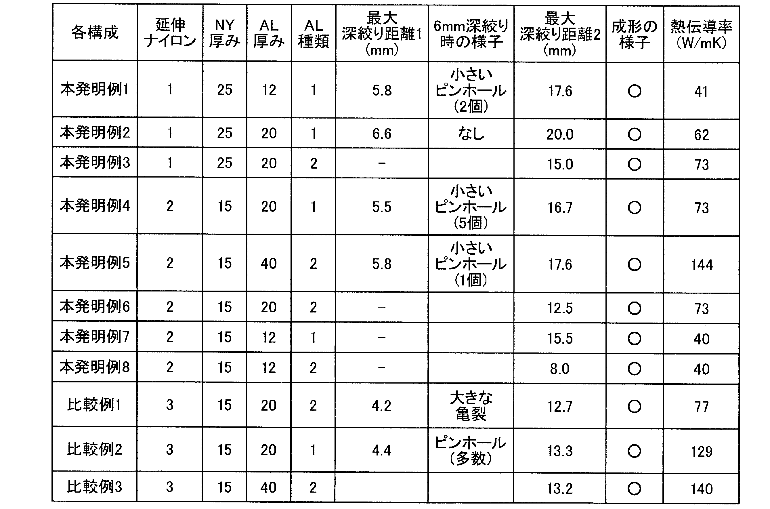
以上のように、第一実施形態に係る包装材用積層体、真空断熱材用包装材及び真空断熱材であれば、本発明が解決しようとする課題を解決し得る。以下、本発明の第一実施形態に係る発明の周辺技術や関連技術について説明する。
家電製品、設備機器、住宅等の建築物における省エネルギー化、特に、住宅用途としては、夏や冬における冷暖房のエネルギーを抑制することを目的として、優れた断熱性能を有する断熱材による、省エネルギー化への推進が求められている。また、高齢化社会で懸念される、風呂場、トイレ、脱衣所等での温度差による心臓への負荷から発生するヒートショックによる心筋梗塞や脳梗塞のリスクを低減させることを目的として、優れた断熱性能を有する断熱材が要求されている。
優れた断熱性能を有する断熱材としては、気密性(ガスバリア性)を有する二枚の積層体を組み合わせて形成した真空断熱材用包装材と、微細な空隙を有する芯材とを備え、真空断熱材用包装材の内部に芯材を真空充填して形成された真空断熱材がある。
真空断熱材は、真空断熱材用包装材の内部を高い真空度に保持し、気体の対流による熱の移動を抑制することによって、高い断熱性能を発揮する。このため、真空断熱材用包装材には、高いガスバリア性が要求されることとなる。
真空断熱材は、真空断熱材用包装材の内部を高い真空度に保持し、気体の対流による熱の移動を抑制することによって、高い断熱性能を発揮する。このため、真空断熱材用包装材には、高いガスバリア性が要求されることとなる。
また、真空断熱材用包装材の内部に、ガラスウール等の芯材を真空充填する際には、真空チャンバー内で上部から圧力を掛けて充填をする。ここで、ガラスウールは、ガラスを10μm以下の繊維状に加工した素材である。
しかしながら、真空チャンバー内で上部から圧力を掛けて、真空断熱材用包装材の内部に芯材を真空充填すると、芯材が内部から積層体を突き破る可能性がある。このため、真空断熱材用包装材には、剛性が要求される。
しかしながら、真空チャンバー内で上部から圧力を掛けて、真空断熱材用包装材の内部に芯材を真空充填すると、芯材が内部から積層体を突き破る可能性がある。このため、真空断熱材用包装材には、剛性が要求される。
また、真空断熱材の使用時にはシール領域を折り曲げる必要があり、シール領域を折り曲げたときに、バリア層にピンホールと呼ばれるクラックが発生してしまうと、真空断熱材の内部が大気圧となり、断熱性能が低下する。このため、真空断熱材用包装材には、耐屈曲性が要求される。
これらの要求に対し、例えば、特許文献1には、剛性や耐屈曲性等の機械的特性に優れたナイロンフィルムを、二層以上積層した構成として、剛性及び耐屈曲性を向上させた構成が開示されている。
これらの要求に対し、例えば、特許文献1には、剛性や耐屈曲性等の機械的特性に優れたナイロンフィルムを、二層以上積層した構成として、剛性及び耐屈曲性を向上させた構成が開示されている。
以上で、特定の実施形態を参照して本発明を説明したが、これら説明によって発明を限定することを意図するものではない。本発明の説明を参照することにより、当業者には、開示された実施形態の種々の変形例とともに本発明の別の実施形態も明らかである。従って、請求の範囲は、本発明の範囲及び要旨に含まれるこれらの変形例または実施形態も網羅すると解すべきである。
1…真空断熱材、2…包装材(真空断熱材用包装材)、4…芯材、6…積層体(包装材用積層体)、8…シール領域、10…充填空間形成領域、12…保護層、14…第一接着層、16…ガスバリア層、18…第二接着層、20…熱溶着層、22…深絞り検証機、24…雄型、26…雌型、28…ストリッパプレート、30…凸部、32…凸部配置空間、34…平面部、61…充填空間形成部、62…シール領域形成部、80…シール部、VL…仮想線、MF…材料フィルム、P…材料フィルムMFの幅方向中心、Alf…アルミニウム合金箔、Alc…アルミニウム結晶
Claims (13)
- 組み合わせた二枚の外周部同士を熱溶着で接合し、真空状態で芯材を充填可能な充填空間が内部に形成される真空断熱材用包装材を形成する包装材用積層体であって、
熱溶着層とガスバリア層と保護層とを順に積層して形成され、
前記保護層は、予め設定した一点を通過して前記保護層の面に沿って放射状に延び、且つ隣り合う線との間隔が45°である四本の仮想線に沿った方向の各破断強度が100N/mm2以上の延伸ナイロンフィルムで形成されていることを特徴とする包装材用積層体。 - 前記仮想線のうち一つは、平面視で、前記延伸ナイロンフィルムの製造時の搬送方向と平行に延びていることを特徴とする請求項1に記載した包装材用積層体。
- 前記延伸ナイロンフィルムは、前記仮想線に沿った方向での伸び率が、80%以上であることを特徴とする請求項1又は請求項2に記載した包装材用積層体。
- 前記保護層の厚さは、9μm以上50μm以下の範囲内であることを特徴とする請求項1から請求項3のうちいずれか1項に記載した包装材用積層体。
- 前記ガスバリア層は、0.7質量%以上1.7質量%以下の範囲内で鉄を含有するアルミニウム合金で形成され、
前記アルミニウム合金が含有するアルミニウム結晶の平均粒径は、6μm以上12μm以下の範囲内であることを特徴とする請求項1から請求項4のうちいずれか1項に記載した包装材用積層体。 - 前記平均粒径が、10μm以下であることを特徴とする請求項5に記載した包装材用積層体。
- 前記平均粒径は、前記ガスバリア層の平面視で、前記アルミニウム合金に対する蛍光X線回折により測定した値であることを特徴とする請求項5又は請求項6に記載した包装材用積層体。
- 前記ガスバリア層の厚さは、9μm以上20μm以下の範囲内であることを特徴とする請求項1から請求項7のうちいずれか1項に記載した包装材用積層体。
- 前記ガスバリア層の厚さは、12μm以下であることを特徴とする請求項8に記載した包装材用積層体。
- 平面視で、前記熱溶着で接合したシール部を形成するための外周側のシール領域と、前記充填空間を形成するための充填空間形成領域と、に区画され、
前記充填空間に対応する形状に形成された充填空間形成部は、前記充填空間形成領域をプレス加工して形成されることを特徴とする請求項1から請求項9のうちいずれか1項に記載した包装材用積層体。 - 組み合わせた二枚の積層体の外周部同士を熱溶着で接合し、真空状態で芯材を充填可能な充填空間が内部に形成された真空断熱材用包装材であって、
前記二枚の積層体のうち少なくとも一方は、請求項1から請求項10のうちいずれか1項に記載した包装材用積層体であることを特徴とする真空断熱材用包装材。 - 前記二枚の積層体のうち少なくとも一方の前記包装材用積層体は、プレス加工により前記充填空間に対応する形状に形成された充填空間形成部を備えることを特徴とする請求項11に記載した真空断熱材用包装材。
- 前記真空断熱材用包装材と、
真空状態で前記充填空間に充填される芯材と、を備え、
組み合わせた二枚の包装材用積層体のうち少なくとも一方は、請求項1から請求項10のうちいずれか1項に記載した包装材用積層体であることを特徴とする真空断熱材。
Priority Applications (1)
| Application Number | Priority Date | Filing Date | Title |
|---|---|---|---|
| JP2016532421A JPWO2016006191A1 (ja) | 2014-07-09 | 2015-06-26 | 包装材用積層体、真空断熱材用包装材及び真空断熱材 |
Applications Claiming Priority (2)
| Application Number | Priority Date | Filing Date | Title |
|---|---|---|---|
| JP2014141158 | 2014-07-09 | ||
| JP2014-141158 | 2014-07-09 |
Publications (1)
| Publication Number | Publication Date |
|---|---|
| WO2016006191A1 true WO2016006191A1 (ja) | 2016-01-14 |
Family
ID=55063847
Family Applications (1)
| Application Number | Title | Priority Date | Filing Date |
|---|---|---|---|
| PCT/JP2015/003228 Ceased WO2016006191A1 (ja) | 2014-07-09 | 2015-06-26 | 包装材用積層体、真空断熱材用包装材及び真空断熱材 |
Country Status (2)
| Country | Link |
|---|---|
| JP (1) | JPWO2016006191A1 (ja) |
| WO (1) | WO2016006191A1 (ja) |
Cited By (4)
| Publication number | Priority date | Publication date | Assignee | Title |
|---|---|---|---|---|
| WO2018062048A1 (ja) * | 2016-09-30 | 2018-04-05 | 大日本印刷株式会社 | 真空断熱材用外包材、真空断熱材、および真空断熱材付き物品 |
| JP2019152284A (ja) * | 2018-03-05 | 2019-09-12 | 大日本印刷株式会社 | 真空断熱材用外包材、真空断熱材、および真空断熱材付き物品 |
| WO2021010416A1 (ja) * | 2019-07-18 | 2021-01-21 | 大日本印刷株式会社 | 真空断熱材用外包材、真空断熱材、および真空断熱材付き物品 |
| KR20240107665A (ko) * | 2022-12-30 | 2024-07-09 | 율촌화학 주식회사 | 고성형성 및 안전성을 가지는 이차전지용 파우치 필름, 이를 이용한 이차전지 및 그 제조 방법 |
Citations (6)
| Publication number | Priority date | Publication date | Assignee | Title |
|---|---|---|---|---|
| JP2003262296A (ja) * | 2002-03-11 | 2003-09-19 | Matsushita Refrig Co Ltd | 真空断熱材、および真空断熱材を使用した冷蔵庫 |
| JP2005022336A (ja) * | 2003-07-04 | 2005-01-27 | Showa Denko Packaging Co Ltd | 成形性に優れた包装用材料及びそれを用いて成形された包装容器 |
| JP2006021429A (ja) * | 2004-07-08 | 2006-01-26 | Matsushita Electric Ind Co Ltd | 真空断熱材 |
| JP2011163415A (ja) * | 2010-02-08 | 2011-08-25 | Sekisui Plastics Co Ltd | 真空断熱材連設シートの製造方法 |
| JP2011181394A (ja) * | 2010-03-02 | 2011-09-15 | Kohjin Co Ltd | 二軸延伸ナイロンフィルムを含む冷間成形用電池ケース包材 |
| WO2013125564A1 (ja) * | 2012-02-20 | 2013-08-29 | 株式会社クラレ | ポリビニルアルコール系蒸着フィルム |
Family Cites Families (3)
| Publication number | Priority date | Publication date | Assignee | Title |
|---|---|---|---|---|
| US6736911B1 (en) * | 1999-07-09 | 2004-05-18 | Toyo Aluminium Kabushiki Kaisha | Aluminum alloy, aluminum alloy foil, container and method of preparing aluminum alloy foil |
| JP2008093933A (ja) * | 2006-10-11 | 2008-04-24 | Matsushita Electric Ind Co Ltd | 真空断熱材 |
| JP2010190304A (ja) * | 2009-02-17 | 2010-09-02 | Fujifilm Corp | 断熱材 |
-
2015
- 2015-06-26 JP JP2016532421A patent/JPWO2016006191A1/ja active Pending
- 2015-06-26 WO PCT/JP2015/003228 patent/WO2016006191A1/ja not_active Ceased
Patent Citations (6)
| Publication number | Priority date | Publication date | Assignee | Title |
|---|---|---|---|---|
| JP2003262296A (ja) * | 2002-03-11 | 2003-09-19 | Matsushita Refrig Co Ltd | 真空断熱材、および真空断熱材を使用した冷蔵庫 |
| JP2005022336A (ja) * | 2003-07-04 | 2005-01-27 | Showa Denko Packaging Co Ltd | 成形性に優れた包装用材料及びそれを用いて成形された包装容器 |
| JP2006021429A (ja) * | 2004-07-08 | 2006-01-26 | Matsushita Electric Ind Co Ltd | 真空断熱材 |
| JP2011163415A (ja) * | 2010-02-08 | 2011-08-25 | Sekisui Plastics Co Ltd | 真空断熱材連設シートの製造方法 |
| JP2011181394A (ja) * | 2010-03-02 | 2011-09-15 | Kohjin Co Ltd | 二軸延伸ナイロンフィルムを含む冷間成形用電池ケース包材 |
| WO2013125564A1 (ja) * | 2012-02-20 | 2013-08-29 | 株式会社クラレ | ポリビニルアルコール系蒸着フィルム |
Cited By (15)
| Publication number | Priority date | Publication date | Assignee | Title |
|---|---|---|---|---|
| CN109790952B (zh) * | 2016-09-30 | 2021-08-13 | 大日本印刷株式会社 | 真空绝热材料用外包装材料、真空绝热材料和带真空绝热材料的物品 |
| JP2018059532A (ja) * | 2016-09-30 | 2018-04-12 | 大日本印刷株式会社 | 真空断熱材用外包材、真空断熱材、および真空断熱材付き物品 |
| CN109790952A (zh) * | 2016-09-30 | 2019-05-21 | 大日本印刷株式会社 | 真空绝热材料用外包装材料、真空绝热材料和带真空绝热材料的物品 |
| WO2018062048A1 (ja) * | 2016-09-30 | 2018-04-05 | 大日本印刷株式会社 | 真空断熱材用外包材、真空断熱材、および真空断熱材付き物品 |
| EP3763988A4 (en) * | 2018-03-05 | 2021-11-17 | Dai Nippon Printing Co., Ltd. | PACKAGING MATERIAL FOR VACUUM THERMAL INSULATION, VACUUM THERMAL INSULATION AND ARTICLES WITH VACUUM THERMAL INSULATION |
| CN111788425A (zh) * | 2018-03-05 | 2020-10-16 | 大日本印刷株式会社 | 真空绝热材料用外包装材料、真空绝热材料和带有真空绝热材料的物品 |
| WO2019172180A1 (ja) * | 2018-03-05 | 2019-09-12 | 大日本印刷株式会社 | 真空断熱材用外包材、真空断熱材、および真空断熱材付き物品 |
| JP2019152284A (ja) * | 2018-03-05 | 2019-09-12 | 大日本印刷株式会社 | 真空断熱材用外包材、真空断熱材、および真空断熱材付き物品 |
| CN111788425B (zh) * | 2018-03-05 | 2022-06-28 | 大日本印刷株式会社 | 真空绝热材料用外包装材料、真空绝热材料和带有真空绝热材料的物品 |
| US11655932B2 (en) * | 2018-03-05 | 2023-05-23 | Dai Nippon Printing Co., Ltd. | Outer packing material for vacuum insulation material, vacuum insulation material, and article provided with vacuum insulation material |
| WO2021010416A1 (ja) * | 2019-07-18 | 2021-01-21 | 大日本印刷株式会社 | 真空断熱材用外包材、真空断熱材、および真空断熱材付き物品 |
| JP2021017905A (ja) * | 2019-07-18 | 2021-02-15 | 大日本印刷株式会社 | 真空断熱材用外包材、真空断熱材、および真空断熱材付き物品 |
| JP7047820B2 (ja) | 2019-07-18 | 2022-04-05 | 大日本印刷株式会社 | 真空断熱材用外包材、真空断熱材、および真空断熱材付き物品 |
| KR20240107665A (ko) * | 2022-12-30 | 2024-07-09 | 율촌화학 주식회사 | 고성형성 및 안전성을 가지는 이차전지용 파우치 필름, 이를 이용한 이차전지 및 그 제조 방법 |
| KR102686970B1 (ko) * | 2022-12-30 | 2024-07-22 | 율촌화학 주식회사 | 고성형성 및 안전성을 가지는 이차전지용 파우치 필름, 이를 이용한 이차전지 및 그 제조 방법 |
Also Published As
| Publication number | Publication date |
|---|---|
| JPWO2016006191A1 (ja) | 2017-04-27 |
Similar Documents
| Publication | Publication Date | Title |
|---|---|---|
| US20230290995A1 (en) | Packaging material for battery | |
| JP6717190B2 (ja) | 蓄電装置用外装材、蓄電装置、及びエンボスタイプ外装材の製造方法 | |
| KR101739637B1 (ko) | 전지 케이스용 포재 및 전지용 케이스 | |
| TWI671186B (zh) | 蓄電裝置用外裝材料、及使用其之蓄電裝置 | |
| US20150225615A1 (en) | Heat-insulation film for high temperature molding, vacuum thermal insulator using same and process for fabricating vacuum thermal insulator | |
| KR102839019B1 (ko) | 축전 디바이스용 외장재 및 당해 외장재를 사용한 축전 디바이스 | |
| JP5999674B2 (ja) | 冷間成形用二軸延伸ナイロンフィルム | |
| US9464430B2 (en) | Vacuum insulation material | |
| TWI760335B (zh) | 蓄電裝置用外裝材及其製造方法 | |
| US12592436B2 (en) | Battery packaging material, manufacturing method therefor, battery, and aluminum alloy foil | |
| KR101752307B1 (ko) | 성형성이 우수한 셀 파우치 | |
| CN205752264U (zh) | 二次电池用外包装材料及二次电池 | |
| JP2019061938A (ja) | 蓄電デバイス用外装材、蓄電デバイス用外装ケース及び蓄電デバイス | |
| JPWO2016006191A1 (ja) | 包装材用積層体、真空断熱材用包装材及び真空断熱材 | |
| TWI760450B (zh) | 蓄電裝置用外裝材及其製造方法 | |
| JP6202174B1 (ja) | 真空断熱材用外包材、真空断熱材、および真空断熱材付き物品 | |
| US10001320B2 (en) | Laminated structure and vacuum insulating material including the same | |
| TW202135360A (zh) | 電池之外裝材用密封薄膜 | |
| JP5467387B2 (ja) | 二軸延伸ナイロンフィルムを含む冷間成形用電池ケース包材 | |
| KR102033006B1 (ko) | 고온 진공단열패널용 난연성 외피재, 이를 이용한 고온 진공단열패널 및 이의 제조방법 | |
| CN116323177A (zh) | 蓄电器件用外包装材料、其制造方法和蓄电器件 | |
| KR101722570B1 (ko) | 진공단열재용 복합강화 난연성 외포재, 이의 제조방법 및 이를 포함하는 진공단열재 | |
| JP2023065303A (ja) | 電池用包装材 | |
| JP2016008706A (ja) | 真空断熱材用包装材及びそれを備えた真空断熱材 | |
| JP6213422B2 (ja) | 包装材 |
Legal Events
| Date | Code | Title | Description |
|---|---|---|---|
| 121 | Ep: the epo has been informed by wipo that ep was designated in this application |
Ref document number: 15819376 Country of ref document: EP Kind code of ref document: A1 |
|
| ENP | Entry into the national phase |
Ref document number: 2016532421 Country of ref document: JP Kind code of ref document: A |
|
| NENP | Non-entry into the national phase |
Ref country code: DE |
|
| 122 | Ep: pct application non-entry in european phase |
Ref document number: 15819376 Country of ref document: EP Kind code of ref document: A1 |