WO2016006073A1 - エンジンカバー - Google Patents
エンジンカバー Download PDFInfo
- Publication number
- WO2016006073A1 WO2016006073A1 PCT/JP2014/068351 JP2014068351W WO2016006073A1 WO 2016006073 A1 WO2016006073 A1 WO 2016006073A1 JP 2014068351 W JP2014068351 W JP 2014068351W WO 2016006073 A1 WO2016006073 A1 WO 2016006073A1
- Authority
- WO
- WIPO (PCT)
- Prior art keywords
- engine
- cover
- mounting portion
- attachment
- engine cover
- Prior art date
- Legal status (The legal status is an assumption and is not a legal conclusion. Google has not performed a legal analysis and makes no representation as to the accuracy of the status listed.)
- Ceased
Links
Images


Classifications
-
- F—MECHANICAL ENGINEERING; LIGHTING; HEATING; WEAPONS; BLASTING
- F02—COMBUSTION ENGINES; HOT-GAS OR COMBUSTION-PRODUCT ENGINE PLANTS
- F02F—CYLINDERS, PISTONS OR CASINGS, FOR COMBUSTION ENGINES; ARRANGEMENTS OF SEALINGS IN COMBUSTION ENGINES
- F02F7/00—Casings, e.g. crankcases
- F02F7/006—Camshaft or pushrod housings
-
- B—PERFORMING OPERATIONS; TRANSPORTING
- B60—VEHICLES IN GENERAL
- B60R—VEHICLES, VEHICLE FITTINGS, OR VEHICLE PARTS, NOT OTHERWISE PROVIDED FOR
- B60R13/00—Elements for body-finishing, identifying, or decorating; Arrangements or adaptations for advertising purposes
- B60R13/08—Insulating elements, e.g. for sound insulation
- B60R13/0838—Insulating elements, e.g. for sound insulation for engine compartments
-
- F—MECHANICAL ENGINEERING; LIGHTING; HEATING; WEAPONS; BLASTING
- F02—COMBUSTION ENGINES; HOT-GAS OR COMBUSTION-PRODUCT ENGINE PLANTS
- F02B—INTERNAL-COMBUSTION PISTON ENGINES; COMBUSTION ENGINES IN GENERAL
- F02B77/00—Component parts, details or accessories, not otherwise provided for
- F02B77/11—Thermal or acoustic insulation
- F02B77/13—Acoustic insulation
Definitions
- the present invention relates to an engine cover that covers an upper portion of an engine in an engine room covered with a bonnet.
- an engine cover is employed for the purpose of reducing the emission of sound emitted by the engine.
- the engine cover is formed of a synthetic resin or the like, and a cover body that covers the upper part of the engine is attached to the upper surface of the engine at a mounting portion that protrudes toward the engine, and is disposed between the engine and the hood in the engine room. ing.
- the engine cover arranged between the bonnet and the engine is required to have a buffering performance in order to protect pedestrians and the like in the event of a collision. That is, in Japanese Patent No. 4062524 (Patent Document 1), the attachment portion of the engine cover to the engine is broken when an impact load is input, and the cover body is displaced so as to sink into the engine side. The load exerted on the colliding pedestrian or the like is reduced.
- the present invention has been made in the background of the above-mentioned circumstances, and the solution to the problem is a novel that can realize buffering performance at the time of collision and avoidance of contact with a vehicle member in a small space. It is to provide an engine cover of structure.
- a first aspect of the present invention is an engine cover having a cover body that covers an upper part of an engine, and an attachment portion that protrudes from the cover body toward the engine side and is attached to the engine side.
- the mounting portion is integrally formed of urethane foam, and a weak portion is provided on the periphery of the mounting portion. When the load is input to the cover body, the mounting portion is deformed in a specific direction by the weak portion. It is characterized by being able to squeeze.
- the deformation direction of the mounting portion with respect to the load input to the cover body is specified by the weakened portion formed in the mounting portion.
- the mounting portion is easily tilted or bent to the side where the weakened portion is formed on the circumference, so that the displacement of the mounting portion and the cover body with respect to a load input due to a collision of a pedestrian or the like can be achieved. Can be controlled to prevent the engine cover from contacting the vehicle parts.
- the cover body and the mounting part are made of foamed urethane, even if a pedestrian collides with the bonnet and the deformed or displaced bonnet comes into contact with the cover body, the pedestrian or the like The impact force exerted on the engine can be prevented from increasing due to the rigidity of the engine cover. Accordingly, the distance between the bonnet and the cover main body can be reduced, and the engine cover can be employed without requiring a large arrangement space in the engine room.
- the cover body and mounting part are made of urethane foam that is flexible, elastic, and has excellent damping performance. It can be absorbed by the energy attenuating action accompanying the deformation of the cover.
- the fragile portion is constituted by a hollow portion that partially opens on the outer periphery of the mounting portion on the circumference. is there.
- the attachment portion by forming the hollow portion opening on the outer peripheral surface of the attachment portion, when a compressive load in the protruding direction is input to the attachment portion, the attachment portion is opened on the opening side of the hollow portion. Therefore, the cover main body and the attachment portion can be deformed in a specific direction.
- the weakened portion can be easily provided by forming the thinned concave portion and changing the shape of the mounting portion on the circumference.
- the fuel system vehicle component or the electrical system vehicle component is disposed on the side opposite to the opening direction of the lightening recess, so that the attachment portion is deformed so as to be bent at the opening portion of the lightening recess. Even so, it is possible to prevent the deformed mounting portion from coming into contact with the fuel system vehicle component or the electrical system vehicle component.
- the cover body when the mounting portion is deformed so as to be bent at the opening portion of the lightening recess, a moment in a specific direction acts on the cover body, and on the side opposite to the opening portion of the lightening recess on the periphery of the mounting portion, the cover Since the main body is easily deformed so as to be separated from the engine side, the cover main body is also less likely to come into contact with the fuel-based vehicle parts and the electrical system-based vehicle parts. Therefore, it is possible to prevent the fuel system vehicle parts and the electrical system system vehicle parts from being damaged by the contact with the engine cover, thereby avoiding the risk of fuel leakage or electrical leakage.
- each of the plurality of attachment portions is provided with the fragile portion, and the fragile portion is provided.
- the deformation directions induced by the fragile portion in the plurality of attachment portions are the same as each other.
- the cover body due to the deformation of each mounting portion by load input to the engine side, the cover body is not only displaced to the engine side but also accompanied by displacement in a specific direction orthogonal to the load input direction, Displaces to the engine side. Therefore, the cover main body becomes difficult to contact the vehicle parts arranged on the engine side, and damage to the vehicle parts is avoided, and the cover main body becomes difficult to contact the engine side, so that the shock due to the deformation of the engine cover can be avoided. The effect is effectively demonstrated with a large stroke.
- each of the plurality of attachment portions is provided with the fragile portion, and the plurality of attachment portions provided with the fragile portion.
- the deformation rigidity is different from each other.
- the mounting portions having different deformation rigidity are deformed in different deformation modes, so that a further excellent buffering effect is exhibited, and the impact force acting on the colliding pedestrian or the like can be reduced. it can.
- both the improvement of the buffering action at the initial stage of the collision and the prevention of the contact of the cover main body with the engine side can be advantageously realized by the stepwise deformation of the attachment portions having different deformation rigidity.
- the mounting parts having different deformation rigidity with respect to the assumed input are deformed at the same time, the impact force acting on the colliding pedestrian and the like is effectively reduced by the buffering action accompanying the deformation of the entire engine cover. Can be done.
- an elastic engagement body formed of a urethane elastomer is fixed to the mounting portion.
- the attachment portion is attached to the engine side by mutually engaging an elastic engagement body and an engagement member provided on the engine side.
- the engine cover is attached to the engine side with sufficient durability and stability of the attachment state by engaging the elastic engagement body fixed to the attachment portion with the engagement member on the engine side.
- the elastic engagement body is formed of a urethane elastomer, the elastic engagement body can be easily and firmly fixed to the mounting portion formed of urethane foam.
- the impact force acting on a pedestrian or the like that has collided with the bonnet is reduced by the deformation of the cover main body and the mounting portion. Is reduced. Furthermore, since the weak part is provided in the attachment part and the deformation direction of the attachment part with respect to the input of the load is specified, it is easy to avoid contact of the cover body and the attachment part with the vehicle parts at the time of load input. Damage to vehicle parts is prevented.
- FIG. 3 The bottom view which shows the engine cover as 1st embodiment of this invention.
- Sectional drawing which shows the deformation
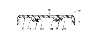
- the engine cover 10 has a structure in which four attachment portions 14, 14, 14, 14 are integrally formed on the cover body 12.
- the up and down direction means the up and down direction in FIG. 2 which is a substantially vertical up and down direction when the vehicle is mounted, and the front and back direction is the left and right direction in FIG.
- the left-right direction means the left-right direction in FIG. 2 that is substantially the left-right direction of the vehicle when the vehicle is mounted.
- the cover main body 12 has a plate shape extending in the front-rear direction and the left-right direction, and is formed of a semi-rigid foam of urethane foam, so that it is lightweight and has a certain degree of rigidity and an excellent shock absorption capacity ( (High attenuation characteristics)
- the cover body 12 can easily achieve the required rigidity and damping performance by adopting closed-cell foamed urethane.
- the open-cell type may be used, and closed-cell and open-cell are mixed. May be.
- the cover body 12 of the present embodiment has a substantially rounded rectangular shape in plan view, and a reinforcing rib 16 that protrudes downward is formed integrally on the outer peripheral end portion continuously over the entire circumference. Has been.
- the urethane foam forming the cover body 12 can be obtained, for example, by forming a foam with a gas generated by the reaction of a glycol component and a diisocyanate component with water during the synthesis of polyurethane. Furthermore, in order to realize a predetermined expansion ratio and expansion mode, a foaming agent, a foam uniformizing agent, or the like may be added. Note that the urethane foam forming the cover body 12 may be either polyether or polyester. Further, in order to effectively obtain a buffering action at the time of collision described later, the urethane foam has a density of 0.08 to 0.15 g / cm 3 .
- a cover layer 18 is formed on the surface (upper surface and outer peripheral surface) of the cover main body 12.
- the covering layer 18 is a thin-walled skin formed of urethane paint, and the lack of the surface of the cover body 12 is covered with the covering layer 18. Note that the covering layer 18 is formed with non-foaming or a remarkably small expansion ratio with respect to the cover main body 12, and a smooth surface can be obtained as compared with the cover main body 12.
- the mounting portion 14 is integrally formed of the same foamed urethane as that of the cover main body 12 and has a substantially truncated cone shape in the reverse direction as shown in FIGS. 1 to 4, and is tapered downward from the cover main body 12. It protrudes at.
- the attachment portion 14 is formed with a meat recess 20 as a fragile portion.
- the cutout recess 20 is a notch-like recess that opens in the outer peripheral surface of the mounting portion 14, and is partially formed on the periphery of the mounting portion 14 as shown in FIG. 1.
- the inner surface of the hollow recess 20 of the present embodiment is composed of a peripheral wall inner surface 22, an upper wall inner surface 24, and a pair of end wall inner surfaces 26, 26. It spreads substantially horizontally perpendicular to the direction.
- each of the four attachment portions 14, 14, 14, and 14 is formed with a lightening recess 20, and each of the lightening recesses 20 opens toward the vehicle rear side.
- the shape of the cut-out recess 20b to be made is different from each other. Specifically, in the hollow recess 20a, the inclination angle of the peripheral wall inner surface 22 with respect to the outer peripheral surface of the mounting portion 14 and the length in the circumferential direction are both smaller than the hollow recess 20b.
- the mounting portion 14 is narrow in the circumferential direction and shallow in the radial direction. Thereby, the mounting portion 14a on the front side of the vehicle in which the thinning recess 20a is formed and the mounting portion 14b on the rear side of the vehicle in which the thinning recess 20b is formed have different deformation rigidity. In the embodiment, the deformation rigidity of the attachment portion 14a is larger than that of the attachment portion 14b.
- an elastic engagement body 28 is attached to the protruding tip portion of the attachment portion 14.
- the elastic engagement body 28 is formed of a urethane-based elastomer and is a rotating body having the cross-sectional shape shown in FIG. More specifically, the elastic engagement body 28 is provided with a central fitting portion 32 having a substantially bottomed cylindrical shape in the opposite direction on the inner peripheral side of the outer peripheral fixing portion 30 having a substantially cylindrical shape.
- the lower end portions of the outer peripheral fixing portion 30 and the central fitting portion 32 have an integrated structure in which they are connected to each other by a taper-shaped intermediate guide portion 34 that gradually increases in diameter downward.
- An annular plate-shaped flange portion 36 that extends to the outer peripheral side is integrally formed at the upper end portion of the outer peripheral fixing portion 30.
- the elastic engagement body 28 is fixed to the lower end portion of the attachment portion 14 in an embedded state in which only the lower surface is exposed. In addition, since the lower surface of the elastic engagement body 28 is exposed from the attachment portion 14, the central hole of the central fitting portion 32 opens on the lower surface of the attachment portion 14.
- the elastic engagement body 28 is fixed to the mounting portion 14 without requiring a special bonding process when the mounting portion 14 is molded. Below, the manufacturing method of the engine cover 10 is demonstrated.
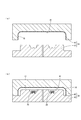
- the coating layer 18 is formed on the cavity inner surface 41 of the upper mold 40 constituting the mold 38 with urethane paint, thereby completing the molding process of the coating layer 18.
- the coating layer 18 can be formed, for example, by spraying urethane coating on the cavity inner surface 41 of the upper mold 40 with a predetermined thickness by spraying or the like and curing it.
- the urethane foam cover is formed by, for example, a casting foam molding method in which the forming material (liquid raw material) of the cover body 12 and the attachment portion 14 is injected into the cavity 44 of the mold 38 and foamed.
- the main body 12 and the attachment portion 14 are molded.
- both the coating layer 18 and the elastic engagement body 28 are formed of a urethane-based material
- the cover layer 12 and the mounting portion 14 made of urethane foam have high affinity, and a special adhesive is used. It is firmly fixed to the cover main body 12 and the mounting portion 14 without requiring application or the like.
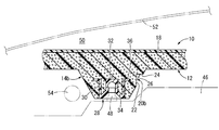
- the engine cover 10 having such a structure is mounted on a vehicle as shown in FIG. That is, the engaging protrusion 48 provided on the upper surface of the engine 46 is fitted into and engaged with the elastic engagement body 28 provided on the mounting portion 14 of the engine cover 10, so that the mounting portion 14 is engaged with the engine 46.
- the cover main body 12 is supported so as to cover the upper side of the engine 46.
- the engagement protrusions 48 on the engine side are engaged with the elastic engagement bodies 28 formed of non-foamed urethane elastomer, the engagement protrusions are formed on the mounting portions 14 formed of foamed urethane. The durability and the stability of the attached state are improved as compared with the case where 48 is directly engaged and attached.
- the engine cover 10 is housed in the engine room 50 and is covered with a hood 52 at the top.
- the bonnet 52 and the engine cover 10 are disposed at a predetermined distance in the vertical direction.
- the sound radiated from the engine 46 is absorbed by the engine cover 10 and the transmission to the hood 52 is reduced.
- both the cover main body 12 and the mounting portion 14 are formed of urethane foam, transmission of sound is more effectively prevented.
- one mounting portion 14b is shown in an enlarged manner, but the four mounting portions 14a, 14a, 14b, 14b are fixed to the engine 46 in the same manner, and the engine cover 10 is It is supported by the engine 46 at several points.
- a fuel pipe 54 as a fuel-based vehicle component is disposed extending left and right.
- the fuel pipe 54 is provided on the side opposite to the formation direction of the thinning recess 20b on the circumference of the mounting portion 14b on the vehicle rear side, and the mounting portion on the vehicle rear side with respect to the mounting portion 14a on the vehicle front side. It is arranged at a position close to 14b.
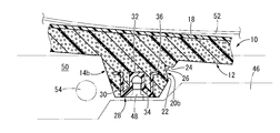
- each mounting portion 14 is formed with a hollow recess 20 that opens to the rear side of the vehicle, and when a large axial compressive force is exerted on the mounting portion 14, as shown in FIG. 14 is deformed so that the opening side of the meat recess 20 is bent in a valley shape, and the upper side from the meat recess 20 is in a specific direction (rear of the vehicle) with respect to the mounting surface of the mounting portion 14 to the engine 46. Can be tilted.
- the cover main body 12 is displaced downward on the vehicle rear side of the mounting portion 14, while being displaced upward on the vehicle front side of the mounting portion 14.
- the fuel pipe 54 is illustrated as a vehicle part that is prevented from contacting the cover body 12, but in addition to the fuel-based vehicle part in which fuel flows or is stored, such as the fuel pipe 54, It is desirable that electrical vehicle components such as a wire harness that is electrically connected to a power source such as an in-vehicle battery and that is energized to avoid contact with the cover body 12. This is because if the lid is covered and the fuel system vehicle component or the electrical system vehicle component is damaged due to contact with the cover body 12, there is a risk of fuel leakage or fire due to electrical leakage.
- electrical vehicle components such as a wire harness that is electrically connected to a power source such as an in-vehicle battery and that is energized to avoid contact with the cover body 12. This is because if the lid is covered and the fuel system vehicle component or the electrical system vehicle component is damaged due to contact with the cover body 12, there is a risk of fuel leakage or fire due to electrical leakage.
- the mounting portion 14 falls to the vehicle rear side and is easily deformed.
- the displacement of the cover body 12 occurs obliquely downward with sliding toward the vehicle rear side.
- the input direction of the collision load with respect to the bonnet 52 is usually inclined toward the rear side of the vehicle, so that the mounting portion 14 is liable to fall down toward the rear side of the vehicle. Therefore, it is possible to ensure a large stroke until the cover body 12 comes into contact with the vehicle parts such as the fuel pipe 54, and it is possible to effectively prevent damage to the vehicle parts due to the contact with the cover body 12 in a space-saving manner. .
- all of the meat recesses 20 formed in the four attachment portions 14, 14, 14, and 14 are open to the vehicle rear side.
- each of the mounting portions 14 is easily deformed to the vehicle rear side, and the cover main body 12 is displaced downward with a slide displacement toward the vehicle rear side, so that the cover main body 12 is made to the fuel pipe 54 and the like. It is difficult to contact the vehicle parts.
- the engine cover 10 is formed of urethane foam that is flexible and excellent in shock absorption capability, as a whole of the cover main body 12 and the mounting portion 14. Therefore, even when the bonnet 52 and the engine cover 10 are arranged close to each other and easily come into contact with each other, the impact force acting on a pedestrian or the like that has collided with the bonnet 52 causes the energy attenuation caused by the deformation of the engine cover 10. Reduced by the action, the safety of pedestrians and the like is improved.
- the hollow recess 20a formed in the mounting portion 14a on the front side of the vehicle and the hollow recess 20b formed on the mounting portion 14b on the rear side of the vehicle have different shapes.
- the deformation rigidity of the mounting portion 14a is larger than the deformation rigidity of the mounting portion 14b.
- the deformation rigidity of the attachment portion 14a located on the vehicle front side is made larger than the deformation rigidity of the attachment portion 14b located on the vehicle rear side.
- the fragile portion is not necessarily limited to the one constituted by the hollow portion, and the peripheral portion of the mounting portion can be formed by changing the material of the forming portion and the foaming ratio partially from the other portions on the circumference.
- a weak part can also be provided on the top.
- the reinforcing member is partially fixed on the circumference of the mounting portion, and a portion where the reinforcing member is removed is made a weak portion, or the shape of the elastic engagement body 28 is changed in the circumferential direction so that the circumference of the mounting portion is changed. It is also possible to provide a fragile part on the surface.
- the structure of the weak part provided in each attachment part does not need to be the same mutually, and may differ.
- the fragile portion is not necessarily provided on the circumference of the mounting portion, and a plurality of fragile portions can be provided so that the deformation of the mounting portion is specified when a load is input.
- the fragile portion is constituted by a hollow recess
- the shape, size, opening direction, number, etc. of the hollow recess are not particularly limited.
- the opening directions of the hollowing recesses formed in the mounting portions may be different from each other.
- the thinning recess 20 is formed in the intermediate portion of the mounting portion 14 in the protruding direction.
- the thinning recess is formed at the end of the mounting portion 14 on the cover body 12 side. You may do it.
- the attachment portion 14 when the attachment portion 14 is compressed by a load input to the cover body 12, the attachment portion 14 is deformed and displaced in a specific direction so as to be inclined with respect to the cover body 12.
- a hollow portion may be formed at the end of the mounting portion 14 on the engine 46 side, and in that case, the displacement of the mounting portion 14 is inclined so as to be inclined with respect to the engine 46 by inputting a compression load. To do.
- the structure in which the weak portions are provided in all the attachment portions 14, 14, 14, 14 is exemplified, but in the present invention, at least one of the attachment portions may be provided with the weak portion,
- the fragile portion can be selectively provided only at the attachment portion provided at a position close to the fuel system vehicle component or the electrical system vehicle component.
- the number of attachment portions 14 is not limited to four. Furthermore, the formation position of the attachment portion 14 with respect to the cover main body 12 is not particularly limited, and can be appropriately provided at an arbitrary position.
- cover main body 12 and the attachment portion 14 in the above embodiment are merely examples, and are not particularly limited.
- the plurality of mounting portions may have different shapes, and the protruding length from the cover body 12, the radial dimension, the cross-sectional shape perpendicular to the axis, and the like may be different from each other.
Landscapes
- Engineering & Computer Science (AREA)
- Mechanical Engineering (AREA)
- Physics & Mathematics (AREA)
- Acoustics & Sound (AREA)
- Chemical & Material Sciences (AREA)
- Combustion & Propulsion (AREA)
- General Engineering & Computer Science (AREA)
- Superstructure Of Vehicle (AREA)
- Cylinder Crankcases Of Internal Combustion Engines (AREA)
Abstract
Description
Claims (6)
- エンジンの上方を覆うカバー本体と、該カバー本体から該エンジン側に突出して該エンジン側に取り付けられる取付部とを、有するエンジンカバーにおいて、
前記カバー本体と前記取付部が発泡ウレタンによって一体形成されていると共に、
該取付部の周上には脆弱部が設けられており、該カバー本体への荷重入力時に該取付部が該脆弱部によって特定方向に変形せしめられるようにしたことを特徴とするエンジンカバー。 - 前記脆弱部が前記取付部の外周面に周上で部分的に開口する肉抜凹部によって構成されている請求項1に記載のエンジンカバー。
- 前記取付部の外周側における前記肉抜凹部の開口とは反対側に燃料系車両部品および電装系車両部品の少なくとも一方が配置されている請求項2に記載のエンジンカバー。
- 複数の前記取付部にそれぞれ前記脆弱部が設けられていると共に、該脆弱部を備えるそれら複数の取付部において該脆弱部によって誘導される変形方向が相互に同じとされている請求項1~3の何れか一項に記載のエンジンカバー。
- 複数の前記取付部にそれぞれ前記脆弱部が設けられていると共に、それら複数の取付部の少なくとも二つにおいて変形剛性が相互に異ならされている請求項4に記載のエンジンカバー。
- 前記取付部にはウレタン系エラストマで形成された弾性係合体が固着されており、該弾性係合体と前記エンジン側に設けられた係合部材とが相互に係合されることによって該取付部が該エンジン側に取り付けられるようにした請求項1~5の何れか一項に記載のエンジンカバー。
Priority Applications (5)
| Application Number | Priority Date | Filing Date | Title |
|---|---|---|---|
| PCT/JP2014/068351 WO2016006073A1 (ja) | 2014-07-09 | 2014-07-09 | エンジンカバー |
| CN201480080506.6A CN106536910B (zh) | 2014-07-09 | 2014-07-09 | 发动机罩 |
| DE112014006868.3T DE112014006868B4 (de) | 2014-07-09 | 2014-07-09 | Motorabdeckung zur Verformung in eine spezifische Richtung |
| JP2015555331A JP6232451B2 (ja) | 2014-07-09 | 2014-07-09 | エンジンカバー |
| US14/974,717 US9995243B2 (en) | 2014-07-09 | 2015-12-18 | Engine cover |
Applications Claiming Priority (1)
| Application Number | Priority Date | Filing Date | Title |
|---|---|---|---|
| PCT/JP2014/068351 WO2016006073A1 (ja) | 2014-07-09 | 2014-07-09 | エンジンカバー |
Related Child Applications (1)
| Application Number | Title | Priority Date | Filing Date |
|---|---|---|---|
| US14/974,717 Continuation US9995243B2 (en) | 2014-07-09 | 2015-12-18 | Engine cover |
Publications (1)
| Publication Number | Publication Date |
|---|---|
| WO2016006073A1 true WO2016006073A1 (ja) | 2016-01-14 |
Family
ID=55063748
Family Applications (1)
| Application Number | Title | Priority Date | Filing Date |
|---|---|---|---|
| PCT/JP2014/068351 Ceased WO2016006073A1 (ja) | 2014-07-09 | 2014-07-09 | エンジンカバー |
Country Status (5)
| Country | Link |
|---|---|
| US (1) | US9995243B2 (ja) |
| JP (1) | JP6232451B2 (ja) |
| CN (1) | CN106536910B (ja) |
| DE (1) | DE112014006868B4 (ja) |
| WO (1) | WO2016006073A1 (ja) |
Cited By (2)
| Publication number | Priority date | Publication date | Assignee | Title |
|---|---|---|---|---|
| JP2020046028A (ja) * | 2018-09-20 | 2020-03-26 | 住友理工株式会社 | カバー装着用グロメット及びカバー |
| JP2022107683A (ja) * | 2017-07-14 | 2022-07-22 | 株式会社イノアックコーポレーション | エンジンカバー |
Families Citing this family (4)
| Publication number | Priority date | Publication date | Assignee | Title |
|---|---|---|---|---|
| GB2562230B (en) * | 2017-05-08 | 2019-12-11 | Jaguar Land Rover Ltd | Thermal encapsulation apparatus |
| US10495024B2 (en) * | 2017-10-05 | 2019-12-03 | Ford Global Technologies, Llc | Reinforced vehicle component cover |
| JP2019094807A (ja) * | 2017-11-21 | 2019-06-20 | 株式会社マーレ フィルターシステムズ | カバー部材 |
| IT202100005282A1 (it) * | 2021-03-08 | 2022-09-08 | Iltar Italbox Ind Riunite S P A | Pannello di copertura funzionale per un motore elettrico di un autoveicolo a propulsione elettrica e procedimento per la sua fabbricazione. |
Citations (4)
| Publication number | Priority date | Publication date | Assignee | Title |
|---|---|---|---|---|
| JP2005153809A (ja) * | 2003-11-27 | 2005-06-16 | Kojima Press Co Ltd | 車両用樹脂部品 |
| JP2011094547A (ja) * | 2009-10-30 | 2011-05-12 | Toyoda Gosei Co Ltd | エンジンカバー |
| JP2012166639A (ja) * | 2011-02-14 | 2012-09-06 | Pacific Ind Co Ltd | 制振用車両部品 |
| JP2014055529A (ja) * | 2012-09-11 | 2014-03-27 | Tokai Rubber Ind Ltd | エンジンカバー |
Family Cites Families (21)
| Publication number | Priority date | Publication date | Assignee | Title |
|---|---|---|---|---|
| USRE31635E (en) * | 1979-06-18 | 1984-07-24 | Gas Spring Corporation | Socket assembly for a ball and socket coupling |
| DE4118557C2 (de) * | 1991-06-06 | 1993-10-14 | Daimler Benz Ag | Kurbelgehäuseentlüftung für eine Brennkraftmaschine |
| ES2191234T3 (es) * | 1997-09-12 | 2003-09-01 | Bollhoff Gmbh | Acoplamiento por enchufe. |
| DE10119892C2 (de) * | 2001-04-24 | 2003-04-03 | Skf Ab | Deckel, insbesondere zur Dämpfung des Geräusches eines Verbrennungsmotors |
| WO2004033930A1 (ja) * | 2002-10-10 | 2004-04-22 | Bridgestone Corporation | Ea材の取付構造 |
| US7004665B2 (en) * | 2002-11-08 | 2006-02-28 | Automotive Components Holdings, Llc | Snap together automotive coupler |
| JP4296493B2 (ja) * | 2003-02-28 | 2009-07-15 | 東海ゴム工業株式会社 | カバーの取付構造 |
| US7082919B2 (en) * | 2003-03-28 | 2006-08-01 | Toyoda Gosei Co., Ltd. | Mounting structure for engine cover |
| JP4062524B2 (ja) * | 2003-03-28 | 2008-03-19 | 豊田合成株式会社 | エンジンカバー |
| DE10317305B4 (de) * | 2003-04-14 | 2006-04-13 | Carcoustics Tech Center Gmbh | Abdeckung für ein Aggregat im Motorraum eines Kraftfahrzeuges |
| JP4285301B2 (ja) * | 2004-03-31 | 2009-06-24 | 豊田合成株式会社 | エンジンカバーの取付構造 |
| JP4296502B2 (ja) * | 2004-10-01 | 2009-07-15 | 豊田合成株式会社 | エンジンカバーの取付構造 |
| JP2006331539A (ja) * | 2005-05-26 | 2006-12-07 | Fujifilm Holdings Corp | 磁気記録媒体およびその製造方法 |
| JP2007170241A (ja) * | 2005-12-21 | 2007-07-05 | Toyota Industries Corp | エンジンカバー構造 |
| JP2008240625A (ja) * | 2007-03-27 | 2008-10-09 | Toyoda Gosei Co Ltd | エンジンカバーの取付け構造 |
| JP5121021B2 (ja) * | 2008-09-30 | 2013-01-16 | 株式会社やまびこ | 内燃エンジン付き作業機 |
| DE102010014079A1 (de) * | 2010-04-07 | 2011-10-13 | Gm Global Technology Operations Llc (N.D.Ges.D. Staates Delaware) | Befestigungseinrichtung einer Abdeckung an einem feststehenden, im Frontbereich angeordneten Bauteil eines Kraftfahrzeuges |
| KR20120094244A (ko) * | 2011-02-16 | 2012-08-24 | (주)대한솔루션 | 흡기장치의 공명기능을 갖는 차량용 엔진커버 |
| JP5654926B2 (ja) * | 2011-03-30 | 2015-01-14 | 住友理工株式会社 | エンジンカバー並びにエンジンの防音構造 |
| DE102011052190A1 (de) * | 2011-07-27 | 2013-01-31 | Böllhoff Verbindungstechnik GmbH | Steckkupplung und Verfahren zu ihrer Herstellung |
| JP6054782B2 (ja) * | 2013-03-19 | 2016-12-27 | スタンレー電気株式会社 | 車両用灯具のピボットホルダ構造 |
-
2014
- 2014-07-09 DE DE112014006868.3T patent/DE112014006868B4/de active Active
- 2014-07-09 WO PCT/JP2014/068351 patent/WO2016006073A1/ja not_active Ceased
- 2014-07-09 JP JP2015555331A patent/JP6232451B2/ja active Active
- 2014-07-09 CN CN201480080506.6A patent/CN106536910B/zh not_active Expired - Fee Related
-
2015
- 2015-12-18 US US14/974,717 patent/US9995243B2/en active Active
Patent Citations (4)
| Publication number | Priority date | Publication date | Assignee | Title |
|---|---|---|---|---|
| JP2005153809A (ja) * | 2003-11-27 | 2005-06-16 | Kojima Press Co Ltd | 車両用樹脂部品 |
| JP2011094547A (ja) * | 2009-10-30 | 2011-05-12 | Toyoda Gosei Co Ltd | エンジンカバー |
| JP2012166639A (ja) * | 2011-02-14 | 2012-09-06 | Pacific Ind Co Ltd | 制振用車両部品 |
| JP2014055529A (ja) * | 2012-09-11 | 2014-03-27 | Tokai Rubber Ind Ltd | エンジンカバー |
Cited By (4)
| Publication number | Priority date | Publication date | Assignee | Title |
|---|---|---|---|---|
| JP2022107683A (ja) * | 2017-07-14 | 2022-07-22 | 株式会社イノアックコーポレーション | エンジンカバー |
| JP7281581B2 (ja) | 2017-07-14 | 2023-05-25 | 株式会社イノアックコーポレーション | エンジンカバー |
| JP2020046028A (ja) * | 2018-09-20 | 2020-03-26 | 住友理工株式会社 | カバー装着用グロメット及びカバー |
| WO2020059636A1 (ja) * | 2018-09-20 | 2020-03-26 | 住友理工株式会社 | カバー装着用グロメット及びカバー |
Also Published As
| Publication number | Publication date |
|---|---|
| JPWO2016006073A1 (ja) | 2017-04-27 |
| US9995243B2 (en) | 2018-06-12 |
| DE112014006868T5 (de) | 2017-05-04 |
| CN106536910B (zh) | 2019-10-01 |
| JP6232451B2 (ja) | 2017-11-15 |
| DE112014006868B4 (de) | 2020-12-10 |
| CN106536910A (zh) | 2017-03-22 |
| US20160102630A1 (en) | 2016-04-14 |
Similar Documents
| Publication | Publication Date | Title |
|---|---|---|
| JP6232451B2 (ja) | エンジンカバー | |
| JP5503537B2 (ja) | バンプストッパ及びその製造方法 | |
| JP5802190B2 (ja) | 自動車の車室側壁構造 | |
| JP5012174B2 (ja) | 車両用フード構造 | |
| JP2010069854A (ja) | 発泡体付き成形部材 | |
| JP2016207358A (ja) | グロメット | |
| JP2018027163A (ja) | 表皮係止用クリップの連結構造 | |
| JP3924304B2 (ja) | 樹脂成形体 | |
| JP5916574B2 (ja) | 車両用ダストカバー組付体およびその製造方法 | |
| CN212354123U (zh) | 方向盘减振系统和方向盘 | |
| JP4439657B2 (ja) | 振動遮断防音材 | |
| JP5942883B2 (ja) | 自動車用外装品 | |
| US12466339B2 (en) | Partition | |
| JP6983045B2 (ja) | 緩衝ストッパ | |
| JP7811512B2 (ja) | 自動車用ドアトリム | |
| JP4461453B2 (ja) | 車両内装部材およびその製造方法 | |
| JP4790328B2 (ja) | 樹脂成形体 | |
| JP2007198312A (ja) | 防音カバー | |
| CN107524364A (zh) | 用于车辆结构件的缓冲件及约束组件 | |
| JP2006144983A (ja) | 防振支持装置 | |
| JP6747890B2 (ja) | 車両用緩衝部品 | |
| KR101980245B1 (ko) | 도어의 임팩트 빔 및 이의 제조방법 | |
| JP4338601B2 (ja) | 自動車用ドア | |
| US10479308B2 (en) | Damping member for vehicle | |
| JP2017136965A (ja) | 車両用緩衝部材 |
Legal Events
| Date | Code | Title | Description |
|---|---|---|---|
| ENP | Entry into the national phase |
Ref document number: 2015555331 Country of ref document: JP Kind code of ref document: A |
|
| 121 | Ep: the epo has been informed by wipo that ep was designated in this application |
Ref document number: 14897118 Country of ref document: EP Kind code of ref document: A1 |
|
| WWE | Wipo information: entry into national phase |
Ref document number: 112014006868 Country of ref document: DE |
|
| 122 | Ep: pct application non-entry in european phase |
Ref document number: 14897118 Country of ref document: EP Kind code of ref document: A1 |