WO2016002266A1 - デスミア処理装置およびデスミア処理方法 - Google Patents
デスミア処理装置およびデスミア処理方法 Download PDFInfo
- Publication number
- WO2016002266A1 WO2016002266A1 PCT/JP2015/058190 JP2015058190W WO2016002266A1 WO 2016002266 A1 WO2016002266 A1 WO 2016002266A1 JP 2015058190 W JP2015058190 W JP 2015058190W WO 2016002266 A1 WO2016002266 A1 WO 2016002266A1
- Authority
- WO
- WIPO (PCT)
- Prior art keywords
- gas
- processing
- desmear
- processing gas
- treatment
- Prior art date
- Legal status (The legal status is an assumption and is not a legal conclusion. Google has not performed a legal analysis and makes no representation as to the accuracy of the status listed.)
- Ceased
Links
Images

Classifications
-
- H—ELECTRICITY
- H05—ELECTRIC TECHNIQUES NOT OTHERWISE PROVIDED FOR
- H05K—PRINTED CIRCUITS; CASINGS OR CONSTRUCTIONAL DETAILS OF ELECTRIC APPARATUS; MANUFACTURE OF ASSEMBLAGES OF ELECTRICAL COMPONENTS
- H05K3/00—Apparatus or processes for manufacturing printed circuits
- H05K3/22—Secondary treatment of printed circuits
- H05K3/26—Cleaning or polishing of the conductive pattern
-
- B—PERFORMING OPERATIONS; TRANSPORTING
- B08—CLEANING
- B08B—CLEANING IN GENERAL; PREVENTION OF FOULING IN GENERAL
- B08B5/00—Cleaning by methods involving the use of air flow or gas flow
-
- B—PERFORMING OPERATIONS; TRANSPORTING
- B08—CLEANING
- B08B—CLEANING IN GENERAL; PREVENTION OF FOULING IN GENERAL
- B08B7/00—Cleaning by methods not provided for in a single other subclass or a single group in this subclass
- B08B7/0035—Cleaning by methods not provided for in a single other subclass or a single group in this subclass by radiant energy, e.g. UV, laser, light beam or the like
- B08B7/0057—Cleaning by methods not provided for in a single other subclass or a single group in this subclass by radiant energy, e.g. UV, laser, light beam or the like by ultraviolet radiation
-
- H—ELECTRICITY
- H05—ELECTRIC TECHNIQUES NOT OTHERWISE PROVIDED FOR
- H05K—PRINTED CIRCUITS; CASINGS OR CONSTRUCTIONAL DETAILS OF ELECTRIC APPARATUS; MANUFACTURE OF ASSEMBLAGES OF ELECTRICAL COMPONENTS
- H05K3/00—Apparatus or processes for manufacturing printed circuits
- H05K3/0011—Working of insulating substrates or insulating layers
- H05K3/0055—After-treatment, e.g. cleaning or desmearing of holes
-
- H—ELECTRICITY
- H01—ELECTRIC ELEMENTS
- H01L—SEMICONDUCTOR DEVICES NOT COVERED BY CLASS H10
- H01L21/00—Processes or apparatus adapted for the manufacture or treatment of semiconductor or solid state devices or of parts thereof
- H01L21/02—Manufacture or treatment of semiconductor devices or of parts thereof
- H01L21/04—Manufacture or treatment of semiconductor devices or of parts thereof the devices having potential barriers, e.g. a PN junction, depletion layer or carrier concentration layer
- H01L21/48—Manufacture or treatment of parts, e.g. containers, prior to assembly of the devices, using processes not provided for in a single one of the groups H01L21/18 - H01L21/326 or H10D48/04 - H10D48/07
- H01L21/4814—Conductive parts
- H01L21/4846—Leads on or in insulating or insulated substrates, e.g. metallisation
- H01L21/486—Via connections through the substrate with or without pins
-
- H—ELECTRICITY
- H05—ELECTRIC TECHNIQUES NOT OTHERWISE PROVIDED FOR
- H05K—PRINTED CIRCUITS; CASINGS OR CONSTRUCTIONAL DETAILS OF ELECTRIC APPARATUS; MANUFACTURE OF ASSEMBLAGES OF ELECTRICAL COMPONENTS
- H05K2203/00—Indexing scheme relating to apparatus or processes for manufacturing printed circuits covered by H05K3/00
- H05K2203/08—Treatments involving gases
- H05K2203/087—Using a reactive gas
-
- H—ELECTRICITY
- H05—ELECTRIC TECHNIQUES NOT OTHERWISE PROVIDED FOR
- H05K—PRINTED CIRCUITS; CASINGS OR CONSTRUCTIONAL DETAILS OF ELECTRIC APPARATUS; MANUFACTURE OF ASSEMBLAGES OF ELECTRICAL COMPONENTS
- H05K2203/00—Indexing scheme relating to apparatus or processes for manufacturing printed circuits covered by H05K3/00
- H05K2203/10—Using electric, magnetic and electromagnetic fields; Using laser light
-
- H—ELECTRICITY
- H05—ELECTRIC TECHNIQUES NOT OTHERWISE PROVIDED FOR
- H05K—PRINTED CIRCUITS; CASINGS OR CONSTRUCTIONAL DETAILS OF ELECTRIC APPARATUS; MANUFACTURE OF ASSEMBLAGES OF ELECTRICAL COMPONENTS
- H05K3/00—Apparatus or processes for manufacturing printed circuits
- H05K3/40—Forming printed elements for providing electric connections to or between printed circuits
- H05K3/42—Plated through-holes or plated via connections
- H05K3/421—Blind plated via connections
Definitions
- the present invention relates to a desmear treatment apparatus and a desmear treatment method for removing smear remaining on a wiring board material in a wiring board manufacturing process.
- a wiring board for mounting a semiconductor element such as a semiconductor integrated circuit element
- a multilayer wiring board in which insulating layers and conductive layers (wiring layers) are alternately stacked is known.
- a via hole or a through hole extending through one or a plurality of insulating layers in the thickness direction is formed.
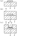
- FIG. 4 is an explanatory view showing an example of the manufacturing process of the multilayer wiring board.
- a conductive layer 3 having a required pattern is formed on the surface of the first insulating layer 2.
- the second insulating layer 4 is formed on the surface of the first insulating layer 2 including the conductive layer 3.
- the through-hole 5 extended through in the thickness direction of the 2nd insulating layer 4 is formed in the required location in the 2nd insulating layer 4 by drilling or laser processing. .
- the smear 6 resulting from the material which comprises a 2nd insulating layer is the inner wall surface of the through-hole 5 in the 2nd insulating layer 4, 2nd insulation, for example It remains in the peripheral region of the through-hole 5 on the surface of the layer 4 and the bottom of the through-hole 5, that is, the portion exposed by the through-hole 5 in the conductive layer 3. For this reason, the desmear process which removes a smear is performed with respect to the wiring board material obtained.
- the processing object including the active species is circulated between the object to be processed and the light transmission window, and the object to be processed is irradiated with ultraviolet rays through the light transmission window.
- the active species source in the processing gas is decomposed and excited to generate active species.
- the smear remaining in the object to be processed reacts with the active species, the smear is decomposed and a decomposition gas such as CO 2 is generated. In this way, smear remaining on the wiring board material is removed.
- JP 2010-205801 A Japanese Patent Laid-Open No. 2007-22796 JP-A-08-180757
- the desmear process by the dry method it is effective to irradiate the wiring board material with ultraviolet rays for a long time in order to sufficiently remove the smear remaining on the wiring board material that is the object to be processed.
- the insulating layer itself constituting the wiring board material is also decomposed.
- a processing gas having a high concentration of the active species source is disposed between the light transmission window and the object to be processed. Means for supplying in between are conceivable.
- the processing gas is supplied so as to flow along the one direction between the light transmission window and the object to be processed.
- oxygen radicals generated by irradiating with ultraviolet rays, and decomposition gas such as CO 2 generated by ashing the object to be processed also form a gap between the light transmission window and the object to be processed. Circulate along one direction.
- the supply amount of the processing gas is large, the generated oxygen radicals immediately move downstream from the region between the light transmission window and the object to be processed. Therefore, the concentration of oxygen radicals between the light transmission window and the object to be processed is lowered, and as a result, it is difficult to sufficiently perform desmear treatment.
- the decomposition gas generated by the decomposition of smear does not immediately move downstream from the region between the light transmission window and the object to be processed.
- transmission window and a to-be-processed object becomes high. Therefore, the oxygen concentration between the light transmission window and the workpiece is relatively low. Along with this, a sufficient amount of oxygen radicals and the like are not generated, and as a result, it is difficult to sufficiently perform desmear treatment.
- an object of the present invention is to provide a desmear treatment apparatus and a desmear treatment method capable of sufficiently removing smear remaining on a workpiece in a short time.
- the desmear processing apparatus of the present invention is disposed between a processing chamber in which an object to be processed is disposed, a light source unit that houses an ultraviolet lamp that irradiates the object to be processed with ultraviolet light, and the processing chamber and the light source unit.
- a desmear treatment apparatus comprising: a light transmission window that transmits ultraviolet light from the ultraviolet lamp; and a treatment gas supply means for supplying a treatment gas containing an active species source to the treatment chamber,
- the processing gas supply means has a processing gas supply source and a control unit for controlling the supply amount of the processing gas from the processing gas supply source,
- the control unit has a function of controlling to supply a processing gas from the processing gas supply source as a purge gas when the object to be processed is irradiated with ultraviolet rays.
- the treatment object in the presence of a treatment gas containing an active species source, the treatment object is irradiated with ultraviolet rays through a light transmission window that transmits the ultraviolet rays, thereby remaining smear remaining on the treatment object.
- a desmear treatment method for removing A reaction step of reacting the active species generated by irradiating the processing gas supplied between the object to be processed and the light transmission window with ultraviolet rays and the smear; the object to be processed and the light transmission;
- a treatment process including a purge step of supplying a purge gas made of the processing gas between the window and the window is repeated.
- the supply amount of the purge gas in the purge step is larger than the supply amount of the processing gas in the reaction step. Moreover, it is preferable that the supply amount of the processing gas in the reaction step is zero.
- the reaction process time is preferably 5 to 15 seconds.
- the number of the treatment processes is preferably 5 to 15 times.
- the active species source is preferably oxygen gas or a mixture of oxygen gas and ozone.
- the object to be processed is irradiated with ultraviolet rays through the light transmission window.
- the present invention by repeating a treatment process comprising a reaction step of irradiating a workpiece with ultraviolet rays in the presence of the treatment gas and a purge step of supplying a purge gas made of the treatment gas,
- the remaining smear can be sufficiently removed in a short time.
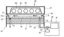
- FIG. 1 is a cross-sectional view illustrating the configuration of an example of the desmear processing apparatus of the present invention.
- the desmear processing apparatus includes a process chamber forming member 10 that forms a process chamber S1 in which a desmear process of the workpiece W is performed, and a light source unit 20 provided above the process chamber forming member 10.
- the workpiece W provided for the desmear treatment apparatus of the present invention is, for example, a substantially flat wiring board material in which holes extending in the thickness direction such as via holes or through holes are formed (see FIG. 4C). ).
- the processing chamber forming member 10 has a rectangular cylindrical casing 15.
- a rectangular plate-shaped mounting table 11 on which the workpiece W is mounted is provided.
- a rectangular frame-shaped spacer member 16 is disposed on the surface of the mounting table 11 along the peripheral edge thereof.
- the upper end portion 15 a of the housing 15 is formed in a state of protruding inward so as to cover the upper surface of the spacer member 16.
- a light source unit 20 is disposed on the upper end portion 15 a of the casing 15 in the processing chamber forming member 10 via a seal member 17. Thereby, between the mounting base 11 and the light source unit 20, processing chamber S1 in which the to-be-processed object W is desmeared is formed.
- the light source unit 20 includes a substantially rectangular parallelepiped box-shaped casing 21 having an opening on the lower surface.
- a light transmission window 30 that transmits vacuum ultraviolet rays is airtightly provided at the opening of the casing 21.
- a sealed lamp housing chamber S2 is formed inside the casing 21.
- a plurality of rod-shaped ultraviolet lamps 25 are arranged in parallel to each other in the same plane.
- a reflection mirror 26 is provided above the ultraviolet lamp 25 in the lamp housing chamber S2.
- the casing 21 is provided with a gas purging means (not shown) for purging the inside of the lamp housing chamber S2 with an inert gas such as nitrogen gas.
- the ultraviolet lamp 25 it is preferable to use a lamp that emits vacuum ultraviolet rays that can excite the active species source.
- Various known lamps can be used as the ultraviolet lamp 25 that radiates vacuum ultraviolet rays.
- the ultraviolet lamp 25 for example, a low-pressure mercury lamp that emits vacuum ultraviolet light of 185 nm, a xenon excimer lamp that emits vacuum ultraviolet light having a center wavelength of 172 nm, or a xenon gas sealed in an arc tube,
- a xenon excimer lamp is preferable.
- any material may be used as long as it has transparency to vacuum ultraviolet rays emitted from the ultraviolet lamp 25 and has resistance to vacuum ultraviolet rays and generated active species.
- synthetic quartz glass can be used as such a material.
- the mounting table 11 is formed with a gas supply hole 12 and a gas discharge hole 13 that respectively penetrate in the thickness direction of the mounting table 11.
- the opening shape in each of the gas supply hole 12 and the gas discharge hole 13 is a strip shape extending along the lamp axis direction of the ultraviolet lamp 25.
- the gas supply holes 12 and the gas discharge holes 13 are formed at positions separated from each other in the arrangement direction of the ultraviolet lamps 25.
- the workpiece W is disposed on the surface of the mounting table 11 at a position between the gas supply hole 12 and the gas discharge hole 13 in the arrangement direction of the ultraviolet lamps 25.
- the total opening area of the gas discharge holes 13 is preferably larger than the total opening area of the gas supply holes 12.
- the gas does not stagnate in the processing chamber S1, and the gas discharge holes 13 are directed toward the gas discharge holes 13. It is distributed in a uniform flow in the direction. Therefore, the gas flow can be stably maintained in the processing chamber S1.
- the dimensions of the opening of the gas supply hole 12 and the gas discharge hole 13 are appropriately designed according to the dimension of the workpiece W.
- the dimension of the opening of the gas supply hole 12 is, for example, The size of the opening of the gas discharge hole 13 is 3 mm ⁇ 600 mm, for example, 10 mm ⁇ 600 mm.
- the gas supply hole 12 is connected to a processing gas supply means 40 for supplying a processing gas to the processing chamber S1 through a gas pipe 45.
- the processing gas supply means 40 adjusts a processing gas supply source 41 in which the processing gas is stored and a valve 43 provided in the gas pipe 45, thereby processing gas from the processing gas supply source 41.
- a control unit 42 for controlling the amount of supply.
- the control unit 42 in the processing gas supply means 40 has a function of controlling to supply the processing gas from the processing gas supply source 41 as a purge gas when the workpiece W is irradiated with vacuum ultraviolet rays.
- the active species source contained in the processing gas may be any source that generates active species upon receiving vacuum ultraviolet rays.
- Specific examples of such active species sources include those that generate oxygen radicals such as oxygen gas (O 2 ) and ozone (O 3 ), those that generate OH radicals such as water vapor, carbon tetrafluoride (CF 4 And the like which generate a fluorine radical such as chlorine gas (Cl 2 ), and those which generate a bromine radical such as hydrogen bromide (HBr).
- the concentration of the active species source in the processing gas is preferably 50% by volume or more, more preferably 70% by volume or more, and still more preferably 90% by volume or more.
- a sufficient amount of active species is generated when the processing gas receives vacuum ultraviolet rays, so that the intended desmear process can be performed reliably.
- the concentration of ozone (O 3 ) in the processing gas is preferably 0.1 to 12% by volume. More preferably, it is 1 to 12% by volume.
- the mounting table 11 is preferably provided with heating means (not shown) for heating the workpiece W.
- heating means not shown for heating the workpiece W.
- the action by the active species can be promoted as the temperature of the surface to be processed of the workpiece W increases. Therefore, the desmear process with respect to the to-be-processed object W can be performed efficiently.
- the processing gas flows through the gas supply hole 12, the heated processing gas can be supplied into the processing chamber S1. Therefore, the temperature of the surface to be processed of the object to be processed W can also be increased by the processing gas flowing along the surface to be processed of the object to be processed W, and as a result, the above-described effect can be obtained more reliably. be able to.
- the heating condition by the heating means is preferably such that the temperature of the surface to be processed W is, for example, 80 ° C. or higher and 340 ° C. or lower, more preferably 80 ° C. or higher and 200 ° C. or lower. It is.
- the desmear processing of the workpiece W is performed as follows using the above desmear processing apparatus.
- the workpiece W is placed at a position between the gas supply hole 12 and the gas discharge hole 13 on the surface of the mounting table 11. Is done.
- the light source unit 20 is disposed on the processing chamber forming member 10 via the seal member 17. Thereby, the light transmission window 30 in the light source unit 20 is disposed so as to face the surface to be processed of the object W to be processed through the gap.
- the to-be-processed object W is heated via the mounting base 11 by a heating means as needed.
- the distance between the light transmission window 30 and the workpiece W is preferably 1 mm or less, more preferably 0.1 to 0.7 mm.
- this distance exceeds 1 mm, most of the vacuum ultraviolet rays are absorbed by the processing gas before the vacuum ultraviolet rays reach the workpiece W from the light transmission window 30 in the reaction step described later.
- the amount of active species generated in the vicinity of the surface of the workpiece W is small, and as a result, the concentration of the active species in the vicinity of the surface of the workpiece W is lowered.
- rate of the smear which exists on the surface of the to-be-processed object W by a vacuum ultraviolet ray falls, processing capacity falls.
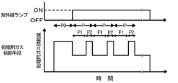
- FIG. 2 is an explanatory diagram showing the operating states of the ultraviolet lamp 25 and the processing gas supply means 40 in the desmear processing apparatus of the present invention.
- the desmear processing method of the present invention will be described with reference to FIG.
- the operation gas is purged by the processing gas supply means 40 as shown in FIG. 3A when the operation of the ultraviolet lamp 25 is stopped (the ultraviolet lamp 25 is turned off).
- G1 is supplied from the gas supply hole 12 to the processing chamber S1.
- the processing gas G1 supplied from the gas supply hole 12 flows between the light transmission window 30 and the workpiece W toward the gas discharge hole 13. Thereafter, the processing gas G1 is discharged to the outside through the gas discharge hole 13. In this way, the processing chamber S1 is purged with the processing gas G1.
- the gas in the treatment chamber S1 may be replaced with, for example, 90% or more of the treatment gas G1.
- the supply amount and supply time of the processing gas G1 are not particularly limited, and can be appropriately set according to the dimensions of the workpiece W and the dimensions of the processing chamber S1.
- the supply amount of the processing gas G1 is 0.1 to 10 L / min, and the supply time is 0.1 to 10 seconds.
- the processing process P is generated by irradiating the processing object W with ultraviolet rays through the light transmission window 30 in the presence of the processing gas G1 supplied between the processing object W and the light transmission window 30.
- vacuum ultraviolet rays are emitted from the ultraviolet lamps 25 by operating the ultraviolet lamps 25.
- the vacuum ultraviolet rays are applied to the workpiece W through the light transmission window 30 and to the processing gas G1 existing between the light transmission window 30 and the workpiece W.
- activated species are generated by decomposing the activated species source contained in the processing gas G1.
- the smear remaining on the workpiece W reacts with the active species, so that the smear is decomposed and a decomposition gas such as CO 2 is generated.
- a processed gas G2 in which the processing gas G1 and the decomposition gas are mixed is generated between the light transmission window 30 and the workpiece W.
- the supply amount of the processing gas G1 is, for example, 0.1 L / min or less, preferably 0 L / min.
- the generated active species stay between the light transmission window 30 and the workpiece W, and the reaction between the active species and smear proceeds with high efficiency. It can be removed in time.
- the supply amount of the processing gas G1 in the reaction process P1 is excessive, the generated active species immediately moves downstream from the region between the light transmission window 30 and the workpiece W. Therefore, the concentration of active species between the light transmission window 30 and the workpiece W is lowered, and as a result, the smear removal efficiency may be reduced.
- the time of the reaction step P1 is preferably 5 to 15 seconds.
- the time of the reaction step P1 is less than 5 seconds, the reaction proceeds to the purge step P2 before the reaction between the generated active species and the smear sufficiently proceeds, and there is a possibility that the smear removal efficiency may be reduced. is there.
- the time of the reaction step P1 exceeds 15 seconds, all the active species generated from the processing gas supplied in the purge step P2 are used up for the reaction, and the reaction between the smear and the active species further proceeds. First, smear removal efficiency may be reduced.
- the processing gas supply means 40 supplies the processing gas G1 as a purge gas from the gas supply hole 12 to the processing chamber S1.
- the processing gas G1 supplied from the gas supply hole 12 flows between the light transmission window 30 and the workpiece W toward the gas discharge hole 13.
- the processed gas G2 between the light transmission window 30 and the workpiece W moves toward the gas discharge hole 13 as shown in FIG. It is discharged outside.
- the processing chamber S1 is purged with the processing gas G1.
- the gas in the processing chamber S1 may be replaced with, for example, 90% or more of the processing gas G1.
- the supply amount of the processing gas (purge gas) G1 is preferably larger than the supply amount of the processing gas G1 in the reaction step P2, specifically 0.1 to 10 L / min. Preferably there is.
- the supply amount of the processing gas G1 in the purge process P2 is too small, the processed gas G2 remains in the processing chamber S1 and cannot be sufficiently replaced with the processing gas G1, and the reaction process P1. There is a risk that it may be difficult to sufficiently supply the active species required in the process.
- the supply amount of the processing gas G1 in the purge process P2 is excessive, the purge process P2 can be shortened to an appropriate time at first glance, but the efficiency seems to be good, but unnecessary turbulence occurs. In some cases, the purge with the treated gas G2 cannot be performed efficiently.
- the time of the purge step P2 is preferably shorter than the time of the reaction step P1, and specifically, it is preferably 10 to 15 seconds.
- the operation of the ultraviolet lamp 25 may be stopped, that is, the irradiation of ultraviolet rays to the workpiece W may be stopped. However, as shown in FIG. It is preferably performed while irradiating with ultraviolet rays through the window 30.
- the number of treatment processes P is preferably 5 to 15 times. When the number of treatment processes P is less than 5, it may be difficult to sufficiently remove smear remaining on the workpiece W. On the other hand, when the number of treatment processes P exceeds 15, the insulating layer itself in the wiring board material that is the workpiece W may be decomposed.
- the processing process P including the reaction process P1 for irradiating the workpiece W with ultraviolet rays in the presence of the processing gas G1 and the purge process P2 for supplying the purge gas made of the processing gas G1 is repeated.
- the processing process P including the reaction process P1 for irradiating the workpiece W with ultraviolet rays in the presence of the processing gas G1 and the purge process P2 for supplying the purge gas made of the processing gas G1 is repeated.
- Example 1 A desmear treatment apparatus was produced according to the configuration shown in FIG. Specific specifications of the desmear processing apparatus are as follows.
- the bottom part (copper foil) of the via hole in the object to be processed was observed with a scanning electron microscope (SEM).
- SEM scanning electron microscope
- the smear remaining at the bottom of the via hole looks blackish, and the part from which the smear has been removed looks whitish. Therefore, when image processing is performed so as to emphasize the black and white of the SEM image, a black region can be recognized as a smear, and a white region can be recognized as a region from which smear has been removed.
- image binarization processing is called image binarization processing. Using this method, the remaining degree of smear was quantified and evaluated.
- the area of the entire bottom of the via hole and the area of the white area are respectively obtained from the SEM image, and the value of “(area of the white area / total area of the bottom of the via hole) ⁇ 100” is calculated, and this is the degree of desmear completion (%) Expressed as: When the desmear is completed, the entire bottom of the via hole becomes white, so the degree of desmear completion is 100%. On the other hand, in the state before the desmear, there is no white area, so the degree of desmear completion is 0%. However, since the image is digitally processed, even if the desmear is completed, the numerical value does not necessarily become 100%. Therefore, 90% or more is desmeared. The results are shown in Table 1.
- Example 1 is the same as Example 1 except that instead of the treatment process consisting of the reaction step and the purge step, the treatment gas supply amount was 0.1 L / min, and the treatment process consisting of only the reaction step for 100 seconds was performed once. Similarly, the desmear process of the to-be-processed object was performed, and the desmear completion degree of the bottom part of the via hole in the to-be-processed object was measured. The results are shown in Table 1.
- Processing chamber forming member 11
- Mounting table 12
- Gas supply hole 13
- Gas discharge hole 15
- Housing 15a
- Upper end portion 16
- Spacer member 17
- Seal member 20
- Light source Unit 21
- Casing 25
- Ultraviolet lamp 26
- Reflecting mirror 30
- Light transmission window 40
- Processing gas supply means 41
- Processing gas supply source 42
- Control unit 43 Valve 45
- Gas pipe P Processing process P0
- Pre-processing process P1 Reaction process
- P2 Purge process
- G1 Processing gas G2 Processed gas
- S1 Processing chamber S2 Lamp storage chamber W Object to be processed
Landscapes
- Engineering & Computer Science (AREA)
- Manufacturing & Machinery (AREA)
- Microelectronics & Electronic Packaging (AREA)
- Physics & Mathematics (AREA)
- Optics & Photonics (AREA)
- Printing Elements For Providing Electric Connections Between Printed Circuits (AREA)
- Drying Of Semiconductors (AREA)
- Cleaning In General (AREA)
Priority Applications (1)
| Application Number | Priority Date | Filing Date | Title |
|---|---|---|---|
| US15/321,163 US20170156217A1 (en) | 2014-06-30 | 2015-03-19 | Desmear treatment device and desmear treatment method |
Applications Claiming Priority (2)
| Application Number | Priority Date | Filing Date | Title |
|---|---|---|---|
| JP2014-133924 | 2014-06-30 | ||
| JP2014133924A JP6102842B2 (ja) | 2014-06-30 | 2014-06-30 | デスミア処理方法およびデスミア処理装置 |
Publications (1)
| Publication Number | Publication Date |
|---|---|
| WO2016002266A1 true WO2016002266A1 (ja) | 2016-01-07 |
Family
ID=55018826
Family Applications (1)
| Application Number | Title | Priority Date | Filing Date |
|---|---|---|---|
| PCT/JP2015/058190 Ceased WO2016002266A1 (ja) | 2014-06-30 | 2015-03-19 | デスミア処理装置およびデスミア処理方法 |
Country Status (3)
| Country | Link |
|---|---|
| US (1) | US20170156217A1 (enExample) |
| JP (1) | JP6102842B2 (enExample) |
| WO (1) | WO2016002266A1 (enExample) |
Families Citing this family (1)
| Publication number | Priority date | Publication date | Assignee | Title |
|---|---|---|---|---|
| CN113518510B (zh) * | 2020-04-10 | 2022-10-11 | 南通深南电路有限公司 | 一种pcb板除胶装置和方法 |
Citations (3)
| Publication number | Priority date | Publication date | Assignee | Title |
|---|---|---|---|---|
| JPS6320833A (ja) * | 1986-07-14 | 1988-01-28 | Toshiba Corp | アツシング装置 |
| JPH05109674A (ja) * | 1991-10-18 | 1993-04-30 | Ushio Inc | レジスト膜の灰化方法と灰化装置 |
| JP2010027702A (ja) * | 2008-07-16 | 2010-02-04 | Hitachi Kokusai Electric Inc | 基板処理装置及び薄膜生成方法 |
Family Cites Families (4)
| Publication number | Priority date | Publication date | Assignee | Title |
|---|---|---|---|---|
| US4328081A (en) * | 1980-02-25 | 1982-05-04 | Micro-Plate, Inc. | Plasma desmearing apparatus and method |
| JPH08180757A (ja) * | 1994-12-21 | 1996-07-12 | Nitto Denko Corp | 接点部の形成方法 |
| JPH10280151A (ja) * | 1997-04-08 | 1998-10-20 | Fujitsu Ltd | Cvd装置のクリーニング方法 |
| US7566664B2 (en) * | 2006-08-02 | 2009-07-28 | Qualcomm Mems Technologies, Inc. | Selective etching of MEMS using gaseous halides and reactive co-etchants |
-
2014
- 2014-06-30 JP JP2014133924A patent/JP6102842B2/ja active Active
-
2015
- 2015-03-19 US US15/321,163 patent/US20170156217A1/en not_active Abandoned
- 2015-03-19 WO PCT/JP2015/058190 patent/WO2016002266A1/ja not_active Ceased
Patent Citations (3)
| Publication number | Priority date | Publication date | Assignee | Title |
|---|---|---|---|---|
| JPS6320833A (ja) * | 1986-07-14 | 1988-01-28 | Toshiba Corp | アツシング装置 |
| JPH05109674A (ja) * | 1991-10-18 | 1993-04-30 | Ushio Inc | レジスト膜の灰化方法と灰化装置 |
| JP2010027702A (ja) * | 2008-07-16 | 2010-02-04 | Hitachi Kokusai Electric Inc | 基板処理装置及び薄膜生成方法 |
Also Published As
| Publication number | Publication date |
|---|---|
| JP6102842B2 (ja) | 2017-03-29 |
| US20170156217A1 (en) | 2017-06-01 |
| JP2016012678A (ja) | 2016-01-21 |
Similar Documents
| Publication | Publication Date | Title |
|---|---|---|
| JP5994821B2 (ja) | デスミア処理装置およびデスミア処理方法 | |
| US20160199887A1 (en) | Desmearing method and desmearing apparatus | |
| JP5895929B2 (ja) | 光照射装置 | |
| KR102036236B1 (ko) | 광처리 장치 및 광처리 방법 | |
| JP5987815B2 (ja) | アッシング方法およびアッシング装置 | |
| JP6102842B2 (ja) | デスミア処理方法およびデスミア処理装置 | |
| JP2016165014A (ja) | デスミア処理装置およびデスミア処理方法 | |
| JP6183202B2 (ja) | アッシング装置およびアッシング方法 | |
| JP5783472B2 (ja) | アッシング装置 | |
| Habu et al. | A Photo-desmear method for via residue removal using a VUV light source | |
| KR101955109B1 (ko) | 광조사 장치 | |
| JP2016189394A (ja) | デスミア用エキシマ光照射装置およびデスミア処理方法 | |
| JP6788842B2 (ja) | 水処理装置 | |
| JP2005317555A (ja) | エキシマランプ及びエキシマ照射装置 | |
| JP6507701B2 (ja) | 光処理装置および光処理方法 | |
| JP6123649B2 (ja) | アッシング装置および被処理物保持構造体 | |
| JP2015103545A (ja) | 光源装置およびデスミア処理装置 | |
| JP2017017070A (ja) | 光処理装置および光処理方法 | |
| TW201639057A (zh) | 光照射裝置 | |
| JP6459578B2 (ja) | 光処理装置および光処理方法 | |
| JP2015122403A (ja) | デスミア処理方法およびデスミア処理装置 |
Legal Events
| Date | Code | Title | Description |
|---|---|---|---|
| 121 | Ep: the epo has been informed by wipo that ep was designated in this application |
Ref document number: 15814151 Country of ref document: EP Kind code of ref document: A1 |
|
| WWE | Wipo information: entry into national phase |
Ref document number: 15321163 Country of ref document: US |
|
| NENP | Non-entry into the national phase |
Ref country code: DE |
|
| 122 | Ep: pct application non-entry in european phase |
Ref document number: 15814151 Country of ref document: EP Kind code of ref document: A1 |