WO2015198432A1 - Procédé de fabrication de bobine de stator à fil plat - Google Patents
Procédé de fabrication de bobine de stator à fil plat Download PDFInfo
- Publication number
- WO2015198432A1 WO2015198432A1 PCT/JP2014/066915 JP2014066915W WO2015198432A1 WO 2015198432 A1 WO2015198432 A1 WO 2015198432A1 JP 2014066915 W JP2014066915 W JP 2014066915W WO 2015198432 A1 WO2015198432 A1 WO 2015198432A1
- Authority
- WO
- WIPO (PCT)
- Prior art keywords
- flat wire
- rectangular
- subassembly
- casting
- stator coil
- Prior art date
Links
Images


Classifications
-
- H—ELECTRICITY
- H02—GENERATION; CONVERSION OR DISTRIBUTION OF ELECTRIC POWER
- H02K—DYNAMO-ELECTRIC MACHINES
- H02K15/00—Methods or apparatus specially adapted for manufacturing, assembling, maintaining or repairing of dynamo-electric machines
- H02K15/08—Forming windings by laying conductors into or around core parts
- H02K15/085—Forming windings by laying conductors into or around core parts by laying conductors into slotted stators
Definitions
- the present invention relates to a method of manufacturing a rectangular stator coil used for an electric motor or the like.
- a stator coil such as an electric motor is wound around a cylindrical stator core.
- the stator core includes a plurality of teeth on the inner periphery at equal angular intervals.
- a slot is formed between adjacent teeth.
- the wire constituting the coil is wound around the teeth through a pair of slots formed with one or more teeth interposed therebetween.
- the wire wound around the teeth protrudes from the end face of the stator core in the axial direction between the pair of slots.
- the coil is a coil that passes through another slot. It intersects the motor axis direction. Crossing takes place at the coil end. The number of intersections depends on the winding pitch of the coil, i.e., how many teeth the winding takes over, and the number of intersections increases with the number of winding pitches.
- Coil end crossing increases the coil end projection length in the axial direction from the end surface of the stator core.
- the crossed coil end conductors are meshed. Weaving was done.
- JP2010-166803A issued by the Japan Patent Office in 2010 to facilitate the winding work, is designed to fit a coil assembly by fitting a wire assembly in which a plurality of wires are coiled into a pair of slots. It has been proposed to form a step in the axial direction at the coil end in advance by winding and providing a crank portion at the coil end of the wire assembly.
- the protruding length in the axial direction of the coil end is inevitable as the number of intersections between the coil and other coils, in other words, the number of winding pitches increases.
- the formation of the step makes it easy to handle the intersection, but the work load of winding the preformed wire around the teeth of the stator core is still not reduced.
- an object of the present invention is to suppress the axial projecting length of the coil end and reduce the work load of the coil winding with respect to the winding of the stator coil.
- the present invention provides a first end surface, a second end surface, a plurality of teeth extending between the first end surface and the second end surface, and an adjacent tooth.
- the present invention is applied to a method of manufacturing a rectangular stator coil in which a rectangular wire is wound around a stator core having a formed slot.
- a rectangular wire element formed in a substantially U-shape is inserted into each pair of slots from the first end face, and each end portion of the flat wire element protrudes from the second end face, and protrudes from the second end face.
- a plurality of rectangular wire pieces forming a stator coil by connecting between predetermined ends of the rectangular wire elements to be formed in advance as a subassembly, the subassembly being disposed on the second end surface, and the rectangular wire pieces of the subassembly. Are joined between predetermined end portions of the flat wire element protruding from the second end face.
- FIG. 1A and 1B are a perspective view of a stator coil manufactured by a method for manufacturing a rectangular stator coil according to an embodiment of the present invention, and an enlarged perspective view of a main part.
- FIG. 2 is a cross-sectional view of a main part of a rectangular stator coil.
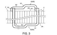
- FIG. 3 is a side view of the main part of the rectangular wire element and the rectangular wire piece constituting the rectangular wire stator coil as viewed from the center direction of the stator core.
- FIG. 4 is a front view of a main part of the rectangular wire element and the rectangular wire piece as viewed from the axial direction of the stator.
- FIG. 5 is a perspective view of the outer rectangular wire element.
- FIG. 6 is a side view of the main part of the flat wire element for one row inserted into the stator core as viewed from the center direction of the stator core.
- FIG. 7 is a front view of a main part of the rectangular wire elements for one row inserted into the stator core as viewed from the axial direction of the stator core.
- FIG. 8 is a perspective view of the inner rectangular wire element.
- FIG. 9 is a perspective view of the outer rectangular wire unit in which the outer rectangular wire elements for two rows are assembled.
- FIG. 10 is a perspective view of an inner rectangular wire unit in which two rows of inner rectangular wire elements are assembled.
- FIG. 11 is a perspective view of a rectangular wire unit that combines an outer rectangular wire unit and an inner rectangular wire unit.
- FIG. 12 is a perspective view of the stator core.
- FIG. 13 is a perspective view of the outer rectangular wire unit inserted in the stator core.
- FIG. 14 is a perspective view of a sub-assembly using a plurality of rectangular wire pieces.
- FIG. 15 is a perspective view of a connected state of the flat wire element and the flat wire piece.
- FIG. 16 is a plan view of a connecting portion between a flat wire element and a flat wire piece.
- FIG. 17 is a cross-sectional view of the main part of the upper mold of the mold for casting the subassembly.
- FIG. 18 is a cross-sectional view of the main part of the middle mold of the mold for casting the subassembly.
- FIG. 19 is a cross-sectional view of the main part of the lower mold of the mold for casting the subassembly.
- FIG. 20 is a perspective view of the subassembly showing the position of the casting hot water portion remaining after casting of the subassembly.
- FIG. 1A and 1B, FIG. 2-7, and FIG. 12 the basic structure of a rectangular stator coil to which the present invention is applied will be described.
- a stator 1 used in an electric motor or the like includes a plurality of sets of coils 3 formed by winding a rectangular wire 6 around a cylindrical stator core 2.
- the flat wire 6 is composed of a conductive wire in which an insulating material is coated on the outer periphery of the copper wire.
- the stator core 2 includes a first end surface 2A and a second end surface 2B in the axial direction. Teeth 4 are formed at equal angular intervals on the inner periphery of the stator core 2. A slot 5 through which the flat wire 6 is inserted is formed between the teeth 4. The slots 5 open to the inner peripheral surface of the stator core 2, the first end surface 2A, and the second end surface 2B, respectively.
- the coil 3 is composed of a flat wire 6 wound around a pair of slots 5 straddling five teeth 4 over four turns, as indicated by oblique lines in the figure. In this way, the flat wire 6 is wound around all the pairs of slots 5 straddling the five teeth 4.
- the plurality of sets of coils 3 attached to the stator core 2 are collectively referred to as a stator coil.
- the rectangular wire 6 constituting each coil 3 includes a rectangular wire element 6A penetrating a predetermined pair of slots 5 of the stator core 2 from the first end surface 2A toward the second end surface 2B, and a second wire 6A.
- the rectangular wire piece 6B is fixed to the end portion of the rectangular wire element 6A that protrudes outward in the axial direction from the end face 2B.
- the flat wire element 6A is configured by cutting the flat wire 6 into a predetermined size in advance and bending it with a bending device or the like to form a substantially U-shape. A portion corresponding to the bottom of the U-shape is bent at a substantially right angle. The bent portion 61 formed in this way is parallel to the first end face 2A in a state where the rectangular wire element 6A is passed through the stator core 2.
- the rectangular wire element 6A is inserted into the predetermined pair of slots 5 from the first end face 2A. Since the flat wire 6 is wound around each pair of slots 5 as described above, four flat wire elements 6A are inserted into each pair of slots 5.
- FIG. 6 and 7 the bent portion 61 of the flat wire element 6A intersects with the bent portion 61 of the other flat wire element 6A in the motor axial direction on the first end face 2A.
- a step 62 is formed in the bent portion 61.
- the rectangular wire piece 6B is fixed to a rectangular wire element 6A that passes through the slot 5 of the stator core 2 and protrudes from the end surface 2B in the axial direction.
- the rectangular wire piece 6B is composed of a rectangular wire 6 cut short.
- the flat wire piece 6 ⁇ / b> B includes a bent portion 63 similar to the bent portion 61 of the flat wire element 6 ⁇ / b> A and a tip 64 extending in a right angle direction from both ends of the bent portion 63.
- a step 62 similar to that of the bent portion 61 is formed in the bent portion 63.
- Both ends 64 of the flat wire 6B are parallel to the end of the flat wire element 6A in a state in which the bent portion 63 of the flat wire 6B is arranged in parallel to the second cross section of the stator core 2.
- the tip 64 of the flat wire piece 6B formed in this way is held in a state in which the tip and the side surface of the flat wire element 6A are in contact with each other in the circumferential direction, and the top surfaces of these tips are joined with the weld metal 20.
- the top surfaces of the distal ends are referred to as a joint pair with the distal end 64 of the flat wire piece 6B and the distal end of the flat wire element 6A.
- the flat wire element 6A joined to one end of the flat wire piece 6B and the flat wire element 6A joined to the other end of the flat wire piece 6B are not the same flat wire element 6A.
- the end of the first flat wire element 6A is joined to one end of the flat wire piece 6B, and the other end of the flat wire piece 6B is adjacent to the first flat wire element 6A and passes through the slot 5. The ends of the flat wire element 6A are joined.
- each of the four rectangular wire pieces 6B is provided at each end of the four rectangular wire elements 6A protruding in the axial direction from the end face 2A.
- the coil 3 is formed by welding the end portions.
- the coil 3 includes four flat wire elements 6A, four flat wire pieces 6B, and eight joint pairs connecting them.
- the distance between the pair of slots 5 penetrating the flat wire element 6A is larger toward the outer peripheral side of the stator core 2 and is smaller at the inner peripheral side.
- the U-shaped width of the flat wire element 6A is narrower in advance as it is arranged closer to the inner side in the radial direction.
- the basic structure of the coil 3 is as described above.
- FIG. A method for manufacturing a rectangular stator coil according to an embodiment of the present invention will be described below with reference to 14-16.
- FIG. 14 in the method for manufacturing a rectangular stator coil according to the embodiment of the present invention, all the rectangular wire pieces 6B are cast in a predetermined overlapped state in advance.
- One subassembly 7 is formed by casting, and the subassembly 7 is fixed to the stator core 2 in which all the flat wire elements 6A are passed through all the slots 5.
- FIGS. 15 and 16 in the subassembly 7, the tip 64 of the flat wire piece 6B and the end of the flat wire element 6A protruding in the axial direction from the second end surface 2B of the stator core 2 are aligned in the circumferential direction. Pre-formed. For this purpose, a gap 21 through which the end of the flat wire element 6A passes is formed between the tip 64 of the flat wire piece 6B of the sub-assembly 7 and another flat wire piece 6B arranged in the circumferential direction. In this embodiment, FIG. As shown in FIG.
- the bent portions 63 of the outer two rows of flat wire pieces 6B are bent outward in the radial direction, and the bent portions 63 of the inner two rows of flat wire pieces 6B are bent inward in the radial direction.
- FIG. 17-19 is perpendicular to the motor axial direction of the die of the sub-assembly 7 for the outer one row of the two outer rows of rectangular wire pieces 6B having the radially outward bent portions 63 for the sake of easy explanation.
- the cross section is shown.
- the basic structure of the mold is the same for the inner one row of flat wire pieces 6B of the outer two rows of flat wire pieces 6B and the inner two rows of flat wire pieces 6B having the bending portions 63 inward in the radial direction. is there.
- FIG. 17 is an upper mold 31
- FIG. 18 is a medium size 32
- FIG. Reference numeral 19 denotes a cross section of a main part of the lower mold 33.
- FIG. Referring to FIG. 18, a liquid cast metal material, that is, a so-called cast hot water, is injected from an inlet (not shown) provided on the outer periphery of the middle mold.
- a hole 35 is formed near the outer periphery of the middle mold 32.
- the hole portion 35 communicates with a hole portion formed in the upper die 31 and the lower die 33.
- the hole 35 is shown in FIG. This corresponds to the step 62 shown in 3, 4, 6, and 7.
- FIG. 17 the rectangular wire piece 6B shown in FIG. Of the rectangular wire piece 6B shown in 3 and 4, it corresponds to the portion near the end face 2B and the tip 64 with the step 62 as a boundary.
- FIG. 19 the rectangular wire piece 6B shown in FIG. Of the flat wire piece 6B shown in 3 and 4, it corresponds to a part far from the end face 2B with the step 62 as a boundary and its tip 64.
- the subassembly 7 in which the flat wire pieces 6B are arranged in advance at a predetermined position is prepared by casting.
- the upper die 31, the middle die 32, and the lower die 33 are also formed with holes for casting the two rectangular wires 6B on the inner side.
- the hot water of the rectangular wire pieces 6B for the two inner rows is injected from an injection port provided on the inner periphery of the middle mold 32.
- the casting assembly 51 is formed on the outer peripheral portion and the casting bath portion 52 is formed on the inner peripheral portion of the subassembly 7 after the upper mold 31, the middle mold 32, and the lower mold 33 are removed after casting. Is done. These hot water parts 51 and 52 are not removed immediately after the subassembly 7 is cast.
- the rectangular wire pieces 6B constituting the subassembly 7 are formed at intervals so as not to contact each other. Therefore, after removing the upper mold 31, the middle mold 32, and the lower mold 33, if the casting hot water parts 51 and 52 are immediately removed from the subassembly 7, the subassembly 7 can hold the rectangular wire piece 6B in a predetermined position. This is not possible, and the flat wire pieces 6B are separated.
- the sub-assembly 7 can maintain a large number of rectangular wire pieces 6B in a predetermined position while being maintained in a self-supporting state. In this state, the subassembly 7 is reliably integrated with resin or the like while maintaining the arrangement of the rectangular wire pieces 6B during casting.
- a heat conductive resin is preferably used as the resin.
- a gap 21 that penetrates the end of the flat wire element 6A is used between the tips 64 adjacent to the peripheral direction of the flat wire piece 6B. Secure.
- the cast hot water portions 51 and 52 are removed by a method such as cutting.
- the subassembly 7 is attached to the tip of the flat wire element 6A protruding in the axial direction from the stator core 2, and the tip 64 of the flat wire piece 6B and the tip of the flat wire element 6A are joined by laser welding, brazing, or the like. .
- FIG. The rectangular stator coil shown in 1A and 1B is completed.
- the casting hot water portions 51 and 52 may be removed after the welding of the tip 64 of the flat wire piece 6B and the tip of the flat wire element 6A is completed. Further, when the sub-assembly 7 after casting can be sufficiently self-supported by the casting runners 51 and 52, the integration with the resin is omitted, and the tip 64 of the rectangular wire piece 6B and the tip of the rectangular wire element 6A are immediately removed. It is also possible to perform welding.
- a plurality of rectangular wire pieces 6B are cast in advance as subassemblies 7 arranged at predetermined positions. The trouble of complicated winding work can be reduced.
- the subassembly 7 immediately after casting keeps the rectangular wire pieces 6B in a predetermined position. It is possible to stand on its own. Therefore, it is not necessary to temporarily fix the rectangular wire piece 6B before being integrated with the resin, and the labor for manufacturing the rectangular wire stator coil can be further reduced.
- the present invention reduces the work load of the coil winding on the stator core. Therefore, for example, a favorable effect can be obtained for rationalization of production of an electric motor for a vehicle.
Landscapes
- Engineering & Computer Science (AREA)
- Manufacturing & Machinery (AREA)
- Power Engineering (AREA)
- Manufacture Of Motors, Generators (AREA)
- Windings For Motors And Generators (AREA)
Abstract
L'invention concerne un noyau de stator qui comprend une pluralité de dents et une pluralité d'encoches, et un fil plat est enroulé autour du noyau de stator en passant par les encoches. Le fil plat est coupé en une longueur prédéterminée et le fil plat coupé est courbé sensiblement en U, ce qui permet de créer une pluralité d'éléments de fil plat. Entretemps, une pluralité de pièces de fil plat (6B) structurées de façon à former des bobines par raccordement des parties d'extrémité prédéterminées des éléments de fil plat sont coulées à l'avance en sous-ensembles (7). Chacun des éléments de fil plat est inséré dans chaque paire prédéterminée d'encoches à partir d'une première surface d'extrémité du noyau de stator, et chacune des parties d'extrémité des éléments de fil plat fait saillie depuis une seconde surface d'extrémité du noyau de stator. Les pièces de fil plat (6B) constituant les sous-ensembles (7) sont fixées aux paires prédéterminées de parties d'extrémité des éléments de fil plat saillant de la seconde surface d'extrémité, ce qui permet de former facilement des bobines de stator équipées d'extrémités de bobine compactes.
Priority Applications (2)
| Application Number | Priority Date | Filing Date | Title |
|---|---|---|---|
| JP2016528927A JP6160774B2 (ja) | 2014-06-25 | 2014-06-25 | 平角線ステータコイルの製造方法 |
| PCT/JP2014/066915 WO2015198432A1 (fr) | 2014-06-25 | 2014-06-25 | Procédé de fabrication de bobine de stator à fil plat |
Applications Claiming Priority (1)
| Application Number | Priority Date | Filing Date | Title |
|---|---|---|---|
| PCT/JP2014/066915 WO2015198432A1 (fr) | 2014-06-25 | 2014-06-25 | Procédé de fabrication de bobine de stator à fil plat |
Publications (1)
| Publication Number | Publication Date |
|---|---|
| WO2015198432A1 true WO2015198432A1 (fr) | 2015-12-30 |
Family
ID=54937562
Family Applications (1)
| Application Number | Title | Priority Date | Filing Date |
|---|---|---|---|
| PCT/JP2014/066915 WO2015198432A1 (fr) | 2014-06-25 | 2014-06-25 | Procédé de fabrication de bobine de stator à fil plat |
Country Status (2)
| Country | Link |
|---|---|
| JP (1) | JP6160774B2 (fr) |
| WO (1) | WO2015198432A1 (fr) |
Cited By (5)
| Publication number | Priority date | Publication date | Assignee | Title |
|---|---|---|---|---|
| GB2559362A (en) * | 2017-02-02 | 2018-08-08 | Safran Electrical & Power | Stator winding for an electrical machine |
| CN109746345A (zh) * | 2018-12-30 | 2019-05-14 | 苏州阿福机器人有限公司 | 一种用于扁线电机绕组中扁线折弯的装置 |
| WO2019233786A1 (fr) | 2018-06-04 | 2019-12-12 | Safran Electrical & Power | Stator d'une machine électrique polyphasée |
| WO2020127597A1 (fr) * | 2018-12-19 | 2020-06-25 | Fraunhofer-Gesellschaft zur Förderung der angewandten Forschung eingetragener Verein | Conducteur électrique et sa fabrication |
| CN112332576A (zh) * | 2020-11-13 | 2021-02-05 | 天津市松正电动汽车技术股份有限公司 | 定子及具有其的电机 |
Citations (4)
| Publication number | Priority date | Publication date | Assignee | Title |
|---|---|---|---|---|
| JP2001292548A (ja) * | 2000-01-31 | 2001-10-19 | Hitachi Ltd | 回転電機の固定子 |
| JP2005269704A (ja) * | 2004-03-16 | 2005-09-29 | Onsei Kigyo Kofun Yugenkoshi | 電動機又は発電機の固定子コイルセット |
| JP2008228541A (ja) * | 2007-03-16 | 2008-09-25 | Mosutetsuku:Kk | コイル及びコイルの製造方法 |
| JP2012186975A (ja) * | 2011-03-08 | 2012-09-27 | Honda Motor Co Ltd | 回転電機のステータ |
Family Cites Families (1)
| Publication number | Priority date | Publication date | Assignee | Title |
|---|---|---|---|---|
| JP2014236574A (ja) * | 2013-05-31 | 2014-12-15 | アイシン・エィ・ダブリュ株式会社 | 誘導回転電機用ロータの製造方法 |
-
2014
- 2014-06-25 JP JP2016528927A patent/JP6160774B2/ja active Active
- 2014-06-25 WO PCT/JP2014/066915 patent/WO2015198432A1/fr active Application Filing
Patent Citations (4)
| Publication number | Priority date | Publication date | Assignee | Title |
|---|---|---|---|---|
| JP2001292548A (ja) * | 2000-01-31 | 2001-10-19 | Hitachi Ltd | 回転電機の固定子 |
| JP2005269704A (ja) * | 2004-03-16 | 2005-09-29 | Onsei Kigyo Kofun Yugenkoshi | 電動機又は発電機の固定子コイルセット |
| JP2008228541A (ja) * | 2007-03-16 | 2008-09-25 | Mosutetsuku:Kk | コイル及びコイルの製造方法 |
| JP2012186975A (ja) * | 2011-03-08 | 2012-09-27 | Honda Motor Co Ltd | 回転電機のステータ |
Cited By (10)
| Publication number | Priority date | Publication date | Assignee | Title |
|---|---|---|---|---|
| GB2559362A (en) * | 2017-02-02 | 2018-08-08 | Safran Electrical & Power | Stator winding for an electrical machine |
| WO2018141814A1 (fr) * | 2017-02-02 | 2018-08-09 | Safran Electrical & Power | Enroulement de stator pour machine électrique |
| CN110235341A (zh) * | 2017-02-02 | 2019-09-13 | 赛峰电气与电源公司 | 电机的定子绕组 |
| CN110235341B (zh) * | 2017-02-02 | 2022-05-13 | 赛峰电气与电源公司 | 电机的定子绕组 |
| WO2019233786A1 (fr) | 2018-06-04 | 2019-12-12 | Safran Electrical & Power | Stator d'une machine électrique polyphasée |
| WO2020127597A1 (fr) * | 2018-12-19 | 2020-06-25 | Fraunhofer-Gesellschaft zur Förderung der angewandten Forschung eingetragener Verein | Conducteur électrique et sa fabrication |
| CN109746345A (zh) * | 2018-12-30 | 2019-05-14 | 苏州阿福机器人有限公司 | 一种用于扁线电机绕组中扁线折弯的装置 |
| CN109746345B (zh) * | 2018-12-30 | 2024-03-22 | 苏州阿福机器人有限公司 | 一种用于扁线电机绕组中扁线折弯的装置 |
| CN112332576A (zh) * | 2020-11-13 | 2021-02-05 | 天津市松正电动汽车技术股份有限公司 | 定子及具有其的电机 |
| CN112332576B (zh) * | 2020-11-13 | 2021-11-26 | 天津松正汽车部件有限公司 | 定子及具有其的电机 |
Also Published As
| Publication number | Publication date |
|---|---|
| JP6160774B2 (ja) | 2017-07-12 |
| JPWO2015198432A1 (ja) | 2017-04-20 |
Similar Documents
| Publication | Publication Date | Title |
|---|---|---|
| JP6260696B2 (ja) | 平角線ステータコイルの製造方法 | |
| JP6160774B2 (ja) | 平角線ステータコイルの製造方法 | |
| JP6324521B2 (ja) | 回転電機の固定子 | |
| JP6098589B2 (ja) | 回転電機ステータ | |
| JP6369293B2 (ja) | 回転電機の固定子 | |
| JP2012165624A (ja) | 回転電機のコイルエンド構造 | |
| JP5565381B2 (ja) | 回転電機の固定子 | |
| JP2015104249A (ja) | 回転電機のコイル接合方法および回転電機のコイル | |
| US11146153B2 (en) | Method of manufacturing a stator of a motor | |
| JP6330670B2 (ja) | ステータの製造方法 | |
| KR101998420B1 (ko) | 헤어핀 접속기구 및 이를 구비한 헤어핀 권선모터 | |
| JP2012257366A (ja) | 回転電機ステータ及びその製造方法 | |
| JP6060017B2 (ja) | 回転電機用のステータの製造方法 | |
| JP2015231277A (ja) | 回転電機のステータとその製造方法及び製造装置 | |
| TWI506924B (zh) | 電機定子及其繞線結構 | |
| JP5002774B2 (ja) | 差動変圧器のボビン構造 | |
| JP5652461B2 (ja) | 回転電機用コイル導線およびコイル体 | |
| JP2013132127A5 (ja) | ブラシレスモータ及び回転電機の固定子 | |
| JP6663942B2 (ja) | 回転電機のステータ | |
| JPWO2017158784A1 (ja) | ステータのインシュレータ及びコイル端末線導入方法 | |
| JP2009044780A (ja) | 回転電機の渡り導体接合型ステータコイル | |
| JP2016052234A (ja) | リード線付回転電機ステータの製造方法 | |
| JP7263890B2 (ja) | 電機子 | |
| JP4670804B2 (ja) | 集中巻ステータコアの整列巻線方法 | |
| WO2014129521A1 (fr) | Procédé de fabrication et dispositif de fabrication pour un stator |
Legal Events
| Date | Code | Title | Description |
|---|---|---|---|
| 121 | Ep: the epo has been informed by wipo that ep was designated in this application |
Ref document number: 14895599 Country of ref document: EP Kind code of ref document: A1 |
|
| ENP | Entry into the national phase |
Ref document number: 2016528927 Country of ref document: JP Kind code of ref document: A |
|
| NENP | Non-entry into the national phase |
Ref country code: DE |
|
| 122 | Ep: pct application non-entry in european phase |
Ref document number: 14895599 Country of ref document: EP Kind code of ref document: A1 |