WO2015198432A1 - Flat wire stator coil manufacturing method - Google Patents
Flat wire stator coil manufacturing method Download PDFInfo
- Publication number
- WO2015198432A1 WO2015198432A1 PCT/JP2014/066915 JP2014066915W WO2015198432A1 WO 2015198432 A1 WO2015198432 A1 WO 2015198432A1 JP 2014066915 W JP2014066915 W JP 2014066915W WO 2015198432 A1 WO2015198432 A1 WO 2015198432A1
- Authority
- WO
- WIPO (PCT)
- Prior art keywords
- flat wire
- rectangular
- subassembly
- casting
- stator coil
- Prior art date
Links
Images


Classifications
-
- H—ELECTRICITY
- H02—GENERATION; CONVERSION OR DISTRIBUTION OF ELECTRIC POWER
- H02K—DYNAMO-ELECTRIC MACHINES
- H02K15/00—Methods or apparatus specially adapted for manufacturing, assembling, maintaining or repairing of dynamo-electric machines
- H02K15/08—Forming windings by laying conductors into or around core parts
- H02K15/085—Forming windings by laying conductors into or around core parts by laying conductors into slotted stators
Definitions
- the present invention relates to a method of manufacturing a rectangular stator coil used for an electric motor or the like.
- a stator coil such as an electric motor is wound around a cylindrical stator core.
- the stator core includes a plurality of teeth on the inner periphery at equal angular intervals.
- a slot is formed between adjacent teeth.
- the wire constituting the coil is wound around the teeth through a pair of slots formed with one or more teeth interposed therebetween.
- the wire wound around the teeth protrudes from the end face of the stator core in the axial direction between the pair of slots.
- the coil is a coil that passes through another slot. It intersects the motor axis direction. Crossing takes place at the coil end. The number of intersections depends on the winding pitch of the coil, i.e., how many teeth the winding takes over, and the number of intersections increases with the number of winding pitches.
- Coil end crossing increases the coil end projection length in the axial direction from the end surface of the stator core.
- the crossed coil end conductors are meshed. Weaving was done.
- JP2010-166803A issued by the Japan Patent Office in 2010 to facilitate the winding work, is designed to fit a coil assembly by fitting a wire assembly in which a plurality of wires are coiled into a pair of slots. It has been proposed to form a step in the axial direction at the coil end in advance by winding and providing a crank portion at the coil end of the wire assembly.
- the protruding length in the axial direction of the coil end is inevitable as the number of intersections between the coil and other coils, in other words, the number of winding pitches increases.
- the formation of the step makes it easy to handle the intersection, but the work load of winding the preformed wire around the teeth of the stator core is still not reduced.
- an object of the present invention is to suppress the axial projecting length of the coil end and reduce the work load of the coil winding with respect to the winding of the stator coil.
- the present invention provides a first end surface, a second end surface, a plurality of teeth extending between the first end surface and the second end surface, and an adjacent tooth.
- the present invention is applied to a method of manufacturing a rectangular stator coil in which a rectangular wire is wound around a stator core having a formed slot.
- a rectangular wire element formed in a substantially U-shape is inserted into each pair of slots from the first end face, and each end portion of the flat wire element protrudes from the second end face, and protrudes from the second end face.
- a plurality of rectangular wire pieces forming a stator coil by connecting between predetermined ends of the rectangular wire elements to be formed in advance as a subassembly, the subassembly being disposed on the second end surface, and the rectangular wire pieces of the subassembly. Are joined between predetermined end portions of the flat wire element protruding from the second end face.
- FIG. 1A and 1B are a perspective view of a stator coil manufactured by a method for manufacturing a rectangular stator coil according to an embodiment of the present invention, and an enlarged perspective view of a main part.
- FIG. 2 is a cross-sectional view of a main part of a rectangular stator coil.
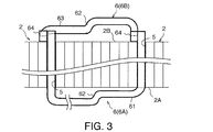
- FIG. 3 is a side view of the main part of the rectangular wire element and the rectangular wire piece constituting the rectangular wire stator coil as viewed from the center direction of the stator core.
- FIG. 4 is a front view of a main part of the rectangular wire element and the rectangular wire piece as viewed from the axial direction of the stator.
- FIG. 5 is a perspective view of the outer rectangular wire element.
- FIG. 6 is a side view of the main part of the flat wire element for one row inserted into the stator core as viewed from the center direction of the stator core.
- FIG. 7 is a front view of a main part of the rectangular wire elements for one row inserted into the stator core as viewed from the axial direction of the stator core.
- FIG. 8 is a perspective view of the inner rectangular wire element.
- FIG. 9 is a perspective view of the outer rectangular wire unit in which the outer rectangular wire elements for two rows are assembled.
- FIG. 10 is a perspective view of an inner rectangular wire unit in which two rows of inner rectangular wire elements are assembled.
- FIG. 11 is a perspective view of a rectangular wire unit that combines an outer rectangular wire unit and an inner rectangular wire unit.
- FIG. 12 is a perspective view of the stator core.
- FIG. 13 is a perspective view of the outer rectangular wire unit inserted in the stator core.
- FIG. 14 is a perspective view of a sub-assembly using a plurality of rectangular wire pieces.
- FIG. 15 is a perspective view of a connected state of the flat wire element and the flat wire piece.
- FIG. 16 is a plan view of a connecting portion between a flat wire element and a flat wire piece.
- FIG. 17 is a cross-sectional view of the main part of the upper mold of the mold for casting the subassembly.
- FIG. 18 is a cross-sectional view of the main part of the middle mold of the mold for casting the subassembly.
- FIG. 19 is a cross-sectional view of the main part of the lower mold of the mold for casting the subassembly.
- FIG. 20 is a perspective view of the subassembly showing the position of the casting hot water portion remaining after casting of the subassembly.
- FIG. 1A and 1B, FIG. 2-7, and FIG. 12 the basic structure of a rectangular stator coil to which the present invention is applied will be described.
- a stator 1 used in an electric motor or the like includes a plurality of sets of coils 3 formed by winding a rectangular wire 6 around a cylindrical stator core 2.
- the flat wire 6 is composed of a conductive wire in which an insulating material is coated on the outer periphery of the copper wire.
- the stator core 2 includes a first end surface 2A and a second end surface 2B in the axial direction. Teeth 4 are formed at equal angular intervals on the inner periphery of the stator core 2. A slot 5 through which the flat wire 6 is inserted is formed between the teeth 4. The slots 5 open to the inner peripheral surface of the stator core 2, the first end surface 2A, and the second end surface 2B, respectively.
- the coil 3 is composed of a flat wire 6 wound around a pair of slots 5 straddling five teeth 4 over four turns, as indicated by oblique lines in the figure. In this way, the flat wire 6 is wound around all the pairs of slots 5 straddling the five teeth 4.
- the plurality of sets of coils 3 attached to the stator core 2 are collectively referred to as a stator coil.
- the rectangular wire 6 constituting each coil 3 includes a rectangular wire element 6A penetrating a predetermined pair of slots 5 of the stator core 2 from the first end surface 2A toward the second end surface 2B, and a second wire 6A.
- the rectangular wire piece 6B is fixed to the end portion of the rectangular wire element 6A that protrudes outward in the axial direction from the end face 2B.
- the flat wire element 6A is configured by cutting the flat wire 6 into a predetermined size in advance and bending it with a bending device or the like to form a substantially U-shape. A portion corresponding to the bottom of the U-shape is bent at a substantially right angle. The bent portion 61 formed in this way is parallel to the first end face 2A in a state where the rectangular wire element 6A is passed through the stator core 2.
- the rectangular wire element 6A is inserted into the predetermined pair of slots 5 from the first end face 2A. Since the flat wire 6 is wound around each pair of slots 5 as described above, four flat wire elements 6A are inserted into each pair of slots 5.
- FIG. 6 and 7 the bent portion 61 of the flat wire element 6A intersects with the bent portion 61 of the other flat wire element 6A in the motor axial direction on the first end face 2A.
- a step 62 is formed in the bent portion 61.
- the rectangular wire piece 6B is fixed to a rectangular wire element 6A that passes through the slot 5 of the stator core 2 and protrudes from the end surface 2B in the axial direction.
- the rectangular wire piece 6B is composed of a rectangular wire 6 cut short.
- the flat wire piece 6 ⁇ / b> B includes a bent portion 63 similar to the bent portion 61 of the flat wire element 6 ⁇ / b> A and a tip 64 extending in a right angle direction from both ends of the bent portion 63.
- a step 62 similar to that of the bent portion 61 is formed in the bent portion 63.
- Both ends 64 of the flat wire 6B are parallel to the end of the flat wire element 6A in a state in which the bent portion 63 of the flat wire 6B is arranged in parallel to the second cross section of the stator core 2.
- the tip 64 of the flat wire piece 6B formed in this way is held in a state in which the tip and the side surface of the flat wire element 6A are in contact with each other in the circumferential direction, and the top surfaces of these tips are joined with the weld metal 20.
- the top surfaces of the distal ends are referred to as a joint pair with the distal end 64 of the flat wire piece 6B and the distal end of the flat wire element 6A.
- the flat wire element 6A joined to one end of the flat wire piece 6B and the flat wire element 6A joined to the other end of the flat wire piece 6B are not the same flat wire element 6A.
- the end of the first flat wire element 6A is joined to one end of the flat wire piece 6B, and the other end of the flat wire piece 6B is adjacent to the first flat wire element 6A and passes through the slot 5. The ends of the flat wire element 6A are joined.
- each of the four rectangular wire pieces 6B is provided at each end of the four rectangular wire elements 6A protruding in the axial direction from the end face 2A.
- the coil 3 is formed by welding the end portions.
- the coil 3 includes four flat wire elements 6A, four flat wire pieces 6B, and eight joint pairs connecting them.
- the distance between the pair of slots 5 penetrating the flat wire element 6A is larger toward the outer peripheral side of the stator core 2 and is smaller at the inner peripheral side.
- the U-shaped width of the flat wire element 6A is narrower in advance as it is arranged closer to the inner side in the radial direction.
- the basic structure of the coil 3 is as described above.
- FIG. A method for manufacturing a rectangular stator coil according to an embodiment of the present invention will be described below with reference to 14-16.
- FIG. 14 in the method for manufacturing a rectangular stator coil according to the embodiment of the present invention, all the rectangular wire pieces 6B are cast in a predetermined overlapped state in advance.
- One subassembly 7 is formed by casting, and the subassembly 7 is fixed to the stator core 2 in which all the flat wire elements 6A are passed through all the slots 5.
- FIGS. 15 and 16 in the subassembly 7, the tip 64 of the flat wire piece 6B and the end of the flat wire element 6A protruding in the axial direction from the second end surface 2B of the stator core 2 are aligned in the circumferential direction. Pre-formed. For this purpose, a gap 21 through which the end of the flat wire element 6A passes is formed between the tip 64 of the flat wire piece 6B of the sub-assembly 7 and another flat wire piece 6B arranged in the circumferential direction. In this embodiment, FIG. As shown in FIG.
- the bent portions 63 of the outer two rows of flat wire pieces 6B are bent outward in the radial direction, and the bent portions 63 of the inner two rows of flat wire pieces 6B are bent inward in the radial direction.
- FIG. 17-19 is perpendicular to the motor axial direction of the die of the sub-assembly 7 for the outer one row of the two outer rows of rectangular wire pieces 6B having the radially outward bent portions 63 for the sake of easy explanation.
- the cross section is shown.
- the basic structure of the mold is the same for the inner one row of flat wire pieces 6B of the outer two rows of flat wire pieces 6B and the inner two rows of flat wire pieces 6B having the bending portions 63 inward in the radial direction. is there.
- FIG. 17 is an upper mold 31
- FIG. 18 is a medium size 32
- FIG. Reference numeral 19 denotes a cross section of a main part of the lower mold 33.
- FIG. Referring to FIG. 18, a liquid cast metal material, that is, a so-called cast hot water, is injected from an inlet (not shown) provided on the outer periphery of the middle mold.
- a hole 35 is formed near the outer periphery of the middle mold 32.
- the hole portion 35 communicates with a hole portion formed in the upper die 31 and the lower die 33.
- the hole 35 is shown in FIG. This corresponds to the step 62 shown in 3, 4, 6, and 7.
- FIG. 17 the rectangular wire piece 6B shown in FIG. Of the rectangular wire piece 6B shown in 3 and 4, it corresponds to the portion near the end face 2B and the tip 64 with the step 62 as a boundary.
- FIG. 19 the rectangular wire piece 6B shown in FIG. Of the flat wire piece 6B shown in 3 and 4, it corresponds to a part far from the end face 2B with the step 62 as a boundary and its tip 64.
- the subassembly 7 in which the flat wire pieces 6B are arranged in advance at a predetermined position is prepared by casting.
- the upper die 31, the middle die 32, and the lower die 33 are also formed with holes for casting the two rectangular wires 6B on the inner side.
- the hot water of the rectangular wire pieces 6B for the two inner rows is injected from an injection port provided on the inner periphery of the middle mold 32.
- the casting assembly 51 is formed on the outer peripheral portion and the casting bath portion 52 is formed on the inner peripheral portion of the subassembly 7 after the upper mold 31, the middle mold 32, and the lower mold 33 are removed after casting. Is done. These hot water parts 51 and 52 are not removed immediately after the subassembly 7 is cast.
- the rectangular wire pieces 6B constituting the subassembly 7 are formed at intervals so as not to contact each other. Therefore, after removing the upper mold 31, the middle mold 32, and the lower mold 33, if the casting hot water parts 51 and 52 are immediately removed from the subassembly 7, the subassembly 7 can hold the rectangular wire piece 6B in a predetermined position. This is not possible, and the flat wire pieces 6B are separated.
- the sub-assembly 7 can maintain a large number of rectangular wire pieces 6B in a predetermined position while being maintained in a self-supporting state. In this state, the subassembly 7 is reliably integrated with resin or the like while maintaining the arrangement of the rectangular wire pieces 6B during casting.
- a heat conductive resin is preferably used as the resin.
- a gap 21 that penetrates the end of the flat wire element 6A is used between the tips 64 adjacent to the peripheral direction of the flat wire piece 6B. Secure.
- the cast hot water portions 51 and 52 are removed by a method such as cutting.
- the subassembly 7 is attached to the tip of the flat wire element 6A protruding in the axial direction from the stator core 2, and the tip 64 of the flat wire piece 6B and the tip of the flat wire element 6A are joined by laser welding, brazing, or the like. .
- FIG. The rectangular stator coil shown in 1A and 1B is completed.
- the casting hot water portions 51 and 52 may be removed after the welding of the tip 64 of the flat wire piece 6B and the tip of the flat wire element 6A is completed. Further, when the sub-assembly 7 after casting can be sufficiently self-supported by the casting runners 51 and 52, the integration with the resin is omitted, and the tip 64 of the rectangular wire piece 6B and the tip of the rectangular wire element 6A are immediately removed. It is also possible to perform welding.
- a plurality of rectangular wire pieces 6B are cast in advance as subassemblies 7 arranged at predetermined positions. The trouble of complicated winding work can be reduced.
- the subassembly 7 immediately after casting keeps the rectangular wire pieces 6B in a predetermined position. It is possible to stand on its own. Therefore, it is not necessary to temporarily fix the rectangular wire piece 6B before being integrated with the resin, and the labor for manufacturing the rectangular wire stator coil can be further reduced.
- the present invention reduces the work load of the coil winding on the stator core. Therefore, for example, a favorable effect can be obtained for rationalization of production of an electric motor for a vehicle.
Abstract
A stator core has a plurality of teeth and a plurality of slots, and a flat wire is wound around the stator core through the slots. The flat wire is cut into a predetermined length and the cut flat wire is bent in a substantially U-shape, thereby creating a plurality of flat wire elements. Meanwhile, a plurality of flat wire pieces (6B) structured so as to form coils by connecting the predetermined end portions of the flat wire elements are cast in advance as subassemblies (7). Each of the flat wire elements is inserted into predetermined each pair of the slots from a first end surface of the stator core, and each of the end portions of the flat wire elements is projected from a second end surface of the stator core. The flat wire pieces (6B) that are the subassemblies (7) are fixed to the predetermined pairs of end portions of the flat wire elements projecting from the second end surface, thereby enabling stator coils equipped with compact coil ends to be easily formed.
Description
この発明は、電動モータなどに使用される平角線ステータコイルの製造方法に関する。
The present invention relates to a method of manufacturing a rectangular stator coil used for an electric motor or the like.
電動モータなどのステータのコイルは、円筒形状のステータコアに巻きつけられる。ステータコアは内周に複数のティースを等しい角度間隔で備える。隣接するティース間にはスロットが形成される。コイルを構成する線材は、一個または複数のティースを挟んで形成された一対のスロットを通してティースに巻き回される。
A stator coil such as an electric motor is wound around a cylindrical stator core. The stator core includes a plurality of teeth on the inner periphery at equal angular intervals. A slot is formed between adjacent teeth. The wire constituting the coil is wound around the teeth through a pair of slots formed with one or more teeth interposed therebetween.
ティースに巻き回された線材は、一対のスロット間においてコイルエンドをステータコアの端面から軸方向に突出する。線材が一個のティースではなく、複数のティースを跨いで巻き回される場合、言い換えれば線材を通す一対のスロットの間に別のスロットが存在する場合には、コイルは別のスロットを通るコイルとモータ軸方向に交差することになる。交差はコイルエンドにおいて行なわれる。交差部の数はコイルの巻線のピッチ、すなわち巻線が幾つのティースをまたいで行なわれるかによって異なり、巻線のピッチ数に応じて交差部の数も増加する。
The wire wound around the teeth protrudes from the end face of the stator core in the axial direction between the pair of slots. When a wire is wound across multiple teeth instead of a single tooth, in other words, when another slot exists between a pair of slots through which the wire passes, the coil is a coil that passes through another slot. It intersects the motor axis direction. Crossing takes place at the coil end. The number of intersections depends on the winding pitch of the coil, i.e., how many teeth the winding takes over, and the number of intersections increases with the number of winding pitches.
コイルエンドの交差はステータコアの端面から軸方向へのコイルエンドの突出長さを増大させる、コイルエンドの軸方向の突出長さを抑えるために、従来は例えば交差するコイルエンドの導線同士を網目状に編み込むことが行なわれていた。
Coil end crossing increases the coil end projection length in the axial direction from the end surface of the stator core. In order to suppress the coil end axial projection length, conventionally, for example, the crossed coil end conductors are meshed. Weaving was done.
この方法では、コイルの線材を1本ずつ編み込むために、コイルの巻線作業が複雑化することは避けられない。巻線作業を容易にすべく、日本国特許庁が2010年に発行したJP2010-166803Aは、複数本の線材をコイル状にまとめた線材集合体を、一対のスロットに嵌め込むことで、コイルの巻線を行なうとともに、線材集合体のコイルエンドにクランク部を設けることで、コイルエンドに軸方向の段差を予め成型しておくことを提案している。
This method inevitably complicates the coil winding work because the coil wire is knitted one by one. JP2010-166803A, issued by the Japan Patent Office in 2010 to facilitate the winding work, is designed to fit a coil assembly by fitting a wire assembly in which a plurality of wires are coiled into a pair of slots. It has been proposed to form a step in the axial direction at the coil end in advance by winding and providing a crank portion at the coil end of the wire assembly.
これにより、コイルエンド同士の交差が容易になる。
This makes it easy to cross coil ends.
しかしながら、この従来技術においても、コイルと他のコイルとの交差部の数、言い換えれば巻線のピッチ数が多くなるにつれて、コイルエンドの軸方向の突出長さが大きくなることは避けられない。
However, even in this conventional technique, the protruding length in the axial direction of the coil end is inevitable as the number of intersections between the coil and other coils, in other words, the number of winding pitches increases.
また、段差を形成することで交差部の処理はやりやすくなるが、予め成形された線材をステータコアのティースに巻き回す作業の負荷は依然として軽減されない。
In addition, the formation of the step makes it easy to handle the intersection, but the work load of winding the preformed wire around the teeth of the stator core is still not reduced.
この発明の目的は、したがって、ステータコイルの巻線に関して、コイルエンドの軸方向の突出長さを抑制するとともに、コイルの巻線の作業負荷を軽減することである。
Therefore, an object of the present invention is to suppress the axial projecting length of the coil end and reduce the work load of the coil winding with respect to the winding of the stator coil.
以上の目的を達成すべく、この発明は、第1の端面と、第2の端面と、第1の端面と第2の端面との間に延在する複数のティースと、隣接するティース間に形成されたスロットと、を有するステータコアに平角線を巻線する平角線ステータコイルの製造方法に適用される。
In order to achieve the above object, the present invention provides a first end surface, a second end surface, a plurality of teeth extending between the first end surface and the second end surface, and an adjacent tooth. The present invention is applied to a method of manufacturing a rectangular stator coil in which a rectangular wire is wound around a stator core having a formed slot.
製造方法は、略U字形に成形された平角線エレメントを第1の端面から各一対のスロットに挿通し、平角線エレメントの各端部を第2の端面から突出させ、第2の端面から突出する平角線エレメントの所定の端部間を接続することでステータコイルを形成する複数の平角線片をあらかじめサブアッセンブリとして成形し、サブアッセンブリを第2の端面に配置し、サブアッセンブリの平角線片を、第2の端面から突出する平角線エレメントの所定の端部間に接合する。
In the manufacturing method, a rectangular wire element formed in a substantially U-shape is inserted into each pair of slots from the first end face, and each end portion of the flat wire element protrudes from the second end face, and protrudes from the second end face. A plurality of rectangular wire pieces forming a stator coil by connecting between predetermined ends of the rectangular wire elements to be formed in advance as a subassembly, the subassembly being disposed on the second end surface, and the rectangular wire pieces of the subassembly. Are joined between predetermined end portions of the flat wire element protruding from the second end face.
この発明の詳細並びに他の特徴や利点は、明細書の以下の記載の中で説明されるとともに、添付された図面に示される。
DETAILED DESCRIPTION Details and other features and advantages of the present invention are described in the following description of the specification and shown in the accompanying drawings.
図面のFIGS.1Aと1B、FIGS.2-7、及びFIG.12を参照してこの発明を適用する平角線ステータコイルの基本構造を説明する。
Figure of the drawing. 1A and 1B, FIG. 2-7, and FIG. 12, the basic structure of a rectangular stator coil to which the present invention is applied will be described.
FIGS.1Aと1Bを参照すると、電動モータなどに用いられるステータ1は円筒形状のステータコア2に平角線6を巻線することで構成された複数組のコイル3を備える。平角線6は銅線の外周に絶縁材をコーティングした導線で構成される。
Fig. Referring to 1A and 1B, a stator 1 used in an electric motor or the like includes a plurality of sets of coils 3 formed by winding a rectangular wire 6 around a cylindrical stator core 2. The flat wire 6 is composed of a conductive wire in which an insulating material is coated on the outer periphery of the copper wire.
FIG.12を参照すると、ステータコア2は軸方向の第1の端面2Aと第2の端面2Bとを備える。ステータコア2の内周には等しい角度間隔でティース4が形成される。ティース4の間には平角線6を挿通させるスロット5が形成される。スロット5はステータコア2の内周面と第1の端面2Aと第2の端面2Bとにそれぞれ開口する。
FIG. Referring to FIG. 12, the stator core 2 includes a first end surface 2A and a second end surface 2B in the axial direction. Teeth 4 are formed at equal angular intervals on the inner periphery of the stator core 2. A slot 5 through which the flat wire 6 is inserted is formed between the teeth 4. The slots 5 open to the inner peripheral surface of the stator core 2, the first end surface 2A, and the second end surface 2B, respectively.
FIG.2を参照すると、コイル3は図の斜線に示すように5個のティース4を跨ぐ一対のスロット5に4周に渡って巻きつけられた平角線6で構成される。このようにして5個のティース4を跨ぐ全ての対のスロット5に平角線6が巻線される。ステータコア2に装着された複数組のコイル3を以下の説明ではステータコイルと総称する。
FIG. Referring to FIG. 2, the coil 3 is composed of a flat wire 6 wound around a pair of slots 5 straddling five teeth 4 over four turns, as indicated by oblique lines in the figure. In this way, the flat wire 6 is wound around all the pairs of slots 5 straddling the five teeth 4. In the following description, the plurality of sets of coils 3 attached to the stator core 2 are collectively referred to as a stator coil.
FIG.3を参照すると、各コイル3を構成する平角線6は、ステータコア2の所定の一対のスロット5を第1の端面2Aから第2の端面2Bに向けて貫通する平角線エレメント6Aと、第2の端面2Bから軸方向外側に突出する平角線エレメント6Aの端部に固定される平角線片6Bとからなる。
FIG. 3, the rectangular wire 6 constituting each coil 3 includes a rectangular wire element 6A penetrating a predetermined pair of slots 5 of the stator core 2 from the first end surface 2A toward the second end surface 2B, and a second wire 6A. The rectangular wire piece 6B is fixed to the end portion of the rectangular wire element 6A that protrudes outward in the axial direction from the end face 2B.
FIG.5を参照すると、平角線エレメント6Aは平角線6をあらかじめ所定の寸法に切断し、ベンディング装置等によって折り曲げ加工して略U字型に形成することで構成される。U字の底部に相当する部位は略直角に折り曲げられる。このようにして形成された折り曲げ部61は平角線エレメント6Aをステータコア2に貫通させた状態で、第1の端面2Aと平行をなす。
FIG. Referring to FIG. 5, the flat wire element 6A is configured by cutting the flat wire 6 into a predetermined size in advance and bending it with a bending device or the like to form a substantially U-shape. A portion corresponding to the bottom of the U-shape is bent at a substantially right angle. The bent portion 61 formed in this way is parallel to the first end face 2A in a state where the rectangular wire element 6A is passed through the stator core 2.
再びFIG.3を参照すると、平角線エレメント6Aは第1の端面2Aから所定の一対のスロット5に挿入される。前述のように平角線6が各対のスロット5に4回巻きつけられることから、各対のスロット5に4個の平角線エレメント6Aが挿入される。
Again FIG. Referring to FIG. 3, the rectangular wire element 6A is inserted into the predetermined pair of slots 5 from the first end face 2A. Since the flat wire 6 is wound around each pair of slots 5 as described above, four flat wire elements 6A are inserted into each pair of slots 5.
FIGS.6と7を参照すると、第1の端面2Aにおいて平角線エレメント6Aの折り曲げ部61は他の平角線エレメント6Aの折り曲げ部61とモータ軸方向に交差する。この交差を容易にするため、折り曲げ部61には段差62が形成される。なお、FIGS.6と7には最も外周側の周方向に並んだ一列分の平角線エレメント6Aのみが記載されているが、実際には各対のスロット5に各4個の平角線エレメント6Aがラジアル方向に重なって配置される。
Fig. 6 and 7, the bent portion 61 of the flat wire element 6A intersects with the bent portion 61 of the other flat wire element 6A in the motor axial direction on the first end face 2A. In order to facilitate this intersection, a step 62 is formed in the bent portion 61. FIG. In FIGS. 6 and 7, only one line of flat wire elements 6A arranged in the circumferential direction on the outermost peripheral side is shown, but in reality, each pair of slots 5 has four flat wire elements 6A in the radial direction. Arranged overlapping.
FIG.4を参照すると、ステータコア2のスロット5を貫通して端面2Bから各端部を軸方向に突出した平角線エレメント6Aに、平角線片6Bが固定される。
FIG. 4, the rectangular wire piece 6B is fixed to a rectangular wire element 6A that passes through the slot 5 of the stator core 2 and protrudes from the end surface 2B in the axial direction.
平角線片6Bは短く切断された平角線6で構成される。平角線片6Bは、平角線エレメント6Aの折り曲げ部61と同様の折り曲げ部63と折り曲げ部63の両端から直角方向に延びる先端64とを備える。折り曲げ部63には折り曲げ部61と同様の段差62が形成される。平角線片6Bの両方の先端64は、平角線片6Bの折り曲げ部63をステータコア2の第2の断面と平行に配置した状態で、平角線エレメント6Aの端部と平行をなす。
The rectangular wire piece 6B is composed of a rectangular wire 6 cut short. The flat wire piece 6 </ b> B includes a bent portion 63 similar to the bent portion 61 of the flat wire element 6 </ b> A and a tip 64 extending in a right angle direction from both ends of the bent portion 63. A step 62 similar to that of the bent portion 61 is formed in the bent portion 63. Both ends 64 of the flat wire 6B are parallel to the end of the flat wire element 6A in a state in which the bent portion 63 of the flat wire 6B is arranged in parallel to the second cross section of the stator core 2.
このように形成された平角線片6Bの先端64を平角線エレメント6Aの先端と側面を周方向に接する状態に保持して、これらの先端の頂面同士を溶接金属20で接合する。先端の頂面同士を平角線片6Bの先端64と平角線エレメント6Aの先端とを、以下の説明では接合対と称する。
The tip 64 of the flat wire piece 6B formed in this way is held in a state in which the tip and the side surface of the flat wire element 6A are in contact with each other in the circumferential direction, and the top surfaces of these tips are joined with the weld metal 20. In the following description, the top surfaces of the distal ends are referred to as a joint pair with the distal end 64 of the flat wire piece 6B and the distal end of the flat wire element 6A.
なお、図において平角線片6Bの一端に接合される平角線エレメント6Aと、平角線片6Bのもう一端に接合される平角線エレメント6Aは、同一の平角線エレメント6Aではない。図において平角線片6Bの一端に第1の平角線エレメント6Aの先端が接合され、平角線片6Bのもう一端には第1の平角線エレメント6Aに隣接してスロット5を貫通する第2の平角線エレメント6Aの端部が接合される。
In the figure, the flat wire element 6A joined to one end of the flat wire piece 6B and the flat wire element 6A joined to the other end of the flat wire piece 6B are not the same flat wire element 6A. In the figure, the end of the first flat wire element 6A is joined to one end of the flat wire piece 6B, and the other end of the flat wire piece 6B is adjacent to the first flat wire element 6A and passes through the slot 5. The ends of the flat wire element 6A are joined.
このようにして各対のスロット5に4個の平角線エレメント6Aを貫通させ、端面2Aから軸方向に突出する4個の平角線エレメント6Aの各端部に4個の平角線片6Bの各端部をそれぞれ溶接することでコイル3が形成される。言い換えれば、コイル3は4個の平角線エレメント6Aと、4個の平角線片6Bと、これらを接続する8個の接合対によって構成される。
In this way, four rectangular wire elements 6A are passed through each pair of slots 5, and each of the four rectangular wire pieces 6B is provided at each end of the four rectangular wire elements 6A protruding in the axial direction from the end face 2A. The coil 3 is formed by welding the end portions. In other words, the coil 3 includes four flat wire elements 6A, four flat wire pieces 6B, and eight joint pairs connecting them.
なお、平角線エレメント6Aを貫通させる一対のスロット5間の距離は、ステータコア2の外周側ほど大きく内周側では小さくなる。このため、平角線エレメント6AのU字の幅は、ラジアル方向内側寄りに配置するものほどあらかじめ狭く形成する。
In addition, the distance between the pair of slots 5 penetrating the flat wire element 6A is larger toward the outer peripheral side of the stator core 2 and is smaller at the inner peripheral side. For this reason, the U-shaped width of the flat wire element 6A is narrower in advance as it is arranged closer to the inner side in the radial direction.
コイル3の基本構造は以上のとおりである。
The basic structure of the coil 3 is as described above.
次にFIGS.14-16を参照して、この発明の実施形態による平角線ステータコイルの製造方法を以下に説明する。
Next, FIG. A method for manufacturing a rectangular stator coil according to an embodiment of the present invention will be described below with reference to 14-16.
以上説明した手順で平角線エレメント6Aと平角線片6Bを順次結合していくと、ステータコイルが完成するまでに膨大な手間がかかる。
If the rectangular wire element 6A and the rectangular wire piece 6B are sequentially coupled in the above-described procedure, it takes a great deal of time to complete the stator coil.
FIG.14を参照すると、この発明の実施形態による平角線ステータコイルの製造方法は、すべての平角線片6Bを予め所定の重なり状態にした形で鋳造する。鋳造によって1個のサブアッセンブリ7を形成し、すべての平角線エレメント6Aをすべてのスロット5に貫通させたステータコア2にサブアッセンブリ7を固定する。すべての平角線片6Bをあらかじめサブアッセンブリ7として鋳造しておくことで、ステータコイルの製造の手間を少なくすることができる。
FIG. Referring to FIG. 14, in the method for manufacturing a rectangular stator coil according to the embodiment of the present invention, all the rectangular wire pieces 6B are cast in a predetermined overlapped state in advance. One subassembly 7 is formed by casting, and the subassembly 7 is fixed to the stator core 2 in which all the flat wire elements 6A are passed through all the slots 5. By casting all the rectangular wire pieces 6B in advance as the subassembly 7, it is possible to reduce the labor of manufacturing the stator coil.
FIGS.15と16を参照すると、サブアッセンブリ7は、平角線片6Bの先端64と、ステータコア2の第2の端面2Bから軸方向に突出する平角線エレメント6Aの端部とが周方向に並ぶようにあらかじめ形成される。そのために、サブアッセンブリ7の平角線片6Bの先端64とこれと周方向に並ぶ別の平角線片6Bの間に平角線エレメント6Aの端部が貫通するギャップ21が形成される。また、この実施形態では、FIG.14に示すように、外側の2列の平角線片6Bの折り曲げ部63はラジアル方向外側へ折り曲げられ、内側の2列の平角線片6Bの折り曲げ部63はラジアル方向内側に折り曲げられる。このように平角線片6Bの折り曲げ方向を外側と内側に分けることで、内側2列の平角線片6Bと外側2列の平角線片6Bとがモータ軸方向で重ならなくなる。その結果、コイル3の第2の端面2Bから軸方向へのコイルエンドの突出長さを小さく抑えることができる。
Fig. Referring to FIGS. 15 and 16, in the subassembly 7, the tip 64 of the flat wire piece 6B and the end of the flat wire element 6A protruding in the axial direction from the second end surface 2B of the stator core 2 are aligned in the circumferential direction. Pre-formed. For this purpose, a gap 21 through which the end of the flat wire element 6A passes is formed between the tip 64 of the flat wire piece 6B of the sub-assembly 7 and another flat wire piece 6B arranged in the circumferential direction. In this embodiment, FIG. As shown in FIG. 14, the bent portions 63 of the outer two rows of flat wire pieces 6B are bent outward in the radial direction, and the bent portions 63 of the inner two rows of flat wire pieces 6B are bent inward in the radial direction. By dividing the bending direction of the flat wire pieces 6B into the outer side and the inner side in this way, the inner two rows of flat wire pieces 6B and the outer two rows of flat wire pieces 6B do not overlap in the motor shaft direction. As a result, the protruding length of the coil end in the axial direction from the second end surface 2B of the coil 3 can be suppressed to a small value.
FIGS.17-19を参照して、サブアッセンブリ7を鋳造するための金型について説明する。なお、FIGS.17-19は、説明を容易にするために、ラジアル方向外側への折り曲げ部63を有する外側2列の平角線片6Bのうち外側1列分のサブアッセンブリ7の金型のモータ軸方向に垂直な断面を示している。外側2列の平角線片6Bのうちの内側1列の平角線片6B及び、ラジアル方向内側へのおき曲げ部63を有する内側2列の平角線片6Bについても金型の基本構造は同じである。
Fig. A mold for casting the subassembly 7 will be described with reference to 17-19. FIG. 17-19 is perpendicular to the motor axial direction of the die of the sub-assembly 7 for the outer one row of the two outer rows of rectangular wire pieces 6B having the radially outward bent portions 63 for the sake of easy explanation. The cross section is shown. The basic structure of the mold is the same for the inner one row of flat wire pieces 6B of the outer two rows of flat wire pieces 6B and the inner two rows of flat wire pieces 6B having the bending portions 63 inward in the radial direction. is there.
FIG.17は上型31、FIG.18は中型32、FIG.19は下型33のそれぞれ要部の断面を示す。
FIG. 17 is an upper mold 31, FIG. 18 is a medium size 32, FIG. Reference numeral 19 denotes a cross section of a main part of the lower mold 33.
FIG.18を参照すると、液状の鋳造金属材料、すなわちいわゆる鋳造湯、は中型の外周部に設けた図示されない注入口から注入される。中型32の外周寄りには孔部35が形成される。孔部35は上型31と下型33内に形成された孔部にそれぞれ連通する。孔部35はFIGS.3,4,6,7に示す段差62に相当する。
FIG. Referring to FIG. 18, a liquid cast metal material, that is, a so-called cast hot water, is injected from an inlet (not shown) provided on the outer periphery of the middle mold. A hole 35 is formed near the outer periphery of the middle mold 32. The hole portion 35 communicates with a hole portion formed in the upper die 31 and the lower die 33. The hole 35 is shown in FIG. This corresponds to the step 62 shown in 3, 4, 6, and 7.
FIG.17を参照すると、図に示された平角線片6Bは、FIGS.3と4に示された平角線片6Bのうち、段差62を境として端面2B 寄りの部位とその先端64に相当する。
FIG. Referring to FIG. 17, the rectangular wire piece 6B shown in FIG. Of the rectangular wire piece 6B shown in 3 and 4, it corresponds to the portion near the end face 2B and the tip 64 with the step 62 as a boundary.
FIG.19を参照すると、図に示された平角線片6Bは、FIGS.3と4に示された平角線片6Bのうち、段差62を境として端面2B から遠い部位とその先端64に相当する。
FIG. Referring to FIG. 19, the rectangular wire piece 6B shown in FIG. Of the flat wire piece 6B shown in 3 and 4, it corresponds to a part far from the end face 2B with the step 62 as a boundary and its tip 64.
このようにして予め平角線片6Bを所定位置に配置したサブアッセンブリ7を鋳造により作成する。なお、実際には、上型31、中型32、及び下型33には、内側2列分の平角線片6Bを鋳造するための孔部も形成される。内側2列分の平角線片6Bの湯は中型32の内周に設けた注入口から注入される。
In this way, the subassembly 7 in which the flat wire pieces 6B are arranged in advance at a predetermined position is prepared by casting. Actually, the upper die 31, the middle die 32, and the lower die 33 are also formed with holes for casting the two rectangular wires 6B on the inner side. The hot water of the rectangular wire pieces 6B for the two inner rows is injected from an injection port provided on the inner periphery of the middle mold 32.
FIG.20を参照すると、鋳造後に上型31,中型32,及び下型33を取り除いた後のサブアッセンブリ7には外周部に鋳造湯回り部51が、内周部に鋳造湯回り部52がそれぞれ形成される。これらの湯回り部51と52はサブアッセンブリ7の鋳造後直ちには除去しない。
FIG. Referring to FIG. 20, the casting assembly 51 is formed on the outer peripheral portion and the casting bath portion 52 is formed on the inner peripheral portion of the subassembly 7 after the upper mold 31, the middle mold 32, and the lower mold 33 are removed after casting. Is done. These hot water parts 51 and 52 are not removed immediately after the subassembly 7 is cast.
サブアッセンブリ7を構成する平角線片6Bは互いに接触しないように間隔をあけて形成される。そのため、上型31、中型32、及び下型33を取り除いた後、直ちにサブアッセンブリ7から鋳造湯回り部51と52を除去すると、サブアッセンブリ7は平角線片6Bを所定位置に保持することができず、平角線片6Bはばらばらになってしまう。
The rectangular wire pieces 6B constituting the subassembly 7 are formed at intervals so as not to contact each other. Therefore, after removing the upper mold 31, the middle mold 32, and the lower mold 33, if the casting hot water parts 51 and 52 are immediately removed from the subassembly 7, the subassembly 7 can hold the rectangular wire piece 6B in a predetermined position. This is not possible, and the flat wire pieces 6B are separated.
鋳造湯回り部51と52を残しておくことで、サブアッセンブリ7は数多くの平角線片6Bを所定位置に保持しつつ自立状態を保つことができる。この状態で、鋳造時の平角線片6Bの配置を保ったままサブアッセンブリ7を樹脂などで確実に一体化する。樹脂には好ましくは伝熱性樹脂が使用される。また、樹脂でサブアッセンブリ7を一体化する際には、平角線片6Bの周方向に隣接する先端64の間に、平角線エレメント6Aの端部を貫通させるギャップ21を、中子などを用いて確保する。
By leaving the casting hot water portions 51 and 52, the sub-assembly 7 can maintain a large number of rectangular wire pieces 6B in a predetermined position while being maintained in a self-supporting state. In this state, the subassembly 7 is reliably integrated with resin or the like while maintaining the arrangement of the rectangular wire pieces 6B during casting. A heat conductive resin is preferably used as the resin. Further, when the subassembly 7 is integrated with resin, a gap 21 that penetrates the end of the flat wire element 6A is used between the tips 64 adjacent to the peripheral direction of the flat wire piece 6B. Secure.
サブアッセンブリ7が樹脂により一体化された後、鋳造湯回り部51と52を切削などの方法で除去する。
After the sub-assembly 7 is integrated with the resin, the cast hot water portions 51 and 52 are removed by a method such as cutting.
次にサブアッセンブリ7をステータコア2から軸方向に突出する平角線エレメント6Aの先端に装着し、平角線片6Bの先端64と平角線エレメント6Aの先端との接合をレーザー溶接、ろう付け等により行なう。
Next, the subassembly 7 is attached to the tip of the flat wire element 6A protruding in the axial direction from the stator core 2, and the tip 64 of the flat wire piece 6B and the tip of the flat wire element 6A are joined by laser welding, brazing, or the like. .
これによりFIGS.1Aと1Bに示す平角線ステータコイルが完成する。
As a result, FIG. The rectangular stator coil shown in 1A and 1B is completed.
鋳造湯回り部51と52の除去は、平角線片6Bの先端64と平角線エレメント6Aの先端との溶接を終了した後に行っても良い。また、鋳造後のサブアッセンブリ7が鋳造湯回り部51と52により十分に自立可能な場合には、樹脂による一体化を省略して、直ちに平角線片6Bの先端64と平角線エレメント6Aの先端との溶接を行なうことも可能である。
The casting hot water portions 51 and 52 may be removed after the welding of the tip 64 of the flat wire piece 6B and the tip of the flat wire element 6A is completed. Further, when the sub-assembly 7 after casting can be sufficiently self-supported by the casting runners 51 and 52, the integration with the resin is omitted, and the tip 64 of the rectangular wire piece 6B and the tip of the rectangular wire element 6A are immediately removed. It is also possible to perform welding.
以上のように、この発明の実施形態による平角線ステータコイルの製造方法は、あらかじめ複数の平角線片6Bを所定位置に配置されたサブアッセンブリ7として鋳造するので、平角線6のステータコア2への複雑な巻線作業の手間を低減することができる。
As described above, in the method for manufacturing a rectangular stator coil according to the embodiment of the present invention, a plurality of rectangular wire pieces 6B are cast in advance as subassemblies 7 arranged at predetermined positions. The trouble of complicated winding work can be reduced.
また、鋳造された数多くの平角線片6Bが樹脂で一体化されるまで、鋳造湯回り部51と52を除去しないため、鋳造直後のサブアッセンブリ7は平角線片6Bを所定位置に保持したまま自立することが可能である。そのため、樹脂で一体化される前の平角線片6Bの仮固定が不要となり、平角線ステータコイルの製造の手間をさらに削減することができる。
Further, since the casting hot water portions 51 and 52 are not removed until a large number of cast rectangular wire pieces 6B are integrated with resin, the subassembly 7 immediately after casting keeps the rectangular wire pieces 6B in a predetermined position. It is possible to stand on its own. Therefore, it is not necessary to temporarily fix the rectangular wire piece 6B before being integrated with the resin, and the labor for manufacturing the rectangular wire stator coil can be further reduced.
以上、この発明を特定の実施形態を通じて説明してきたが、この発明は上記の実施形態に限定されるものではない。当業者にとっては、クレームの技術範囲で上記の実施形態にさまざまな修正あるいは変更を加えることが可能である。
As mentioned above, although this invention has been described through specific embodiments, this invention is not limited to the above embodiments. Those skilled in the art can make various modifications or changes to the above-described embodiments within the technical scope of the claims.
以上のように、この発明は、ステータコアへのコイルの巻線の作業負荷を軽減する。したがって、例えば車両用の電動モータの生産の合理化に好ましい効果が得られる。
As described above, the present invention reduces the work load of the coil winding on the stator core. Therefore, for example, a favorable effect can be obtained for rationalization of production of an electric motor for a vehicle.
この発明の実施形態が包含する排他的性質あるいは特長は以下のようにクレームされる。
The exclusive property or feature included in the embodiment of the present invention is claimed as follows.
Claims (4)
- 第1の端面と、第2の端面と、第1の端面と第2の端面との間に延在する複数のティースと、隣接するティース間に形成されたスロットと、を有するステータコアに、スロットを通して平角線を巻線する平角線ステータコイルの製造方法において:
略U字形状に形成された複数の平角線エレメントの各々を第1の端面から所定の各一対のスロットに挿通し、平角線エレメントの各端部を第2の端面から突出させ;
複数の平角線エレメントの所定の端部間を接続することでコイルを形成するように構成された複数の平角線片をあらかじめサブアッセンブリとして鋳造し;
サブアッセンブリの平角線片を、第2の端面から突出する平角線エレメントの所定の一対の端部に固定することで、サブアッセンブリを第2の端面に装着する、
平角線ステータコイルの製造方法。 A slot in a stator core having a first end face, a second end face, a plurality of teeth extending between the first end face and the second end face, and a slot formed between adjacent teeth. In a method of manufacturing a rectangular stator coil that winds a rectangular wire through:
Each of a plurality of flat wire elements formed in a substantially U shape is inserted into a predetermined pair of slots from the first end surface, and each end portion of the flat wire element is projected from the second end surface;
A plurality of rectangular wire pieces configured to form a coil by connecting predetermined ends of a plurality of rectangular wire elements are cast as sub-assemblies in advance;
The sub-assembly is attached to the second end surface by fixing the rectangular wire piece of the sub-assembly to a predetermined pair of ends of the flat wire element protruding from the second end surface.
A manufacturing method of a rectangular stator coil. - サブアッセンブリは環状断面の金型の内周と外周からそれぞれ鋳造湯を注入することで鋳造されるとともに、鋳造によりサブアッセンブリの内周と外周とに残存する鋳造湯回り部を、サブアッセンブリを第2の端面に装着した後に除去する、請求項1の平角線ステータコイルの製造方法。 The subassembly is cast by injecting casting water from the inner periphery and the outer periphery of the die having an annular cross section, and the casting assembly around the inner periphery and the outer periphery of the subassembly is cast, and the subassembly is moved to the second position. The method for manufacturing a rectangular stator coil according to claim 1, wherein the rectangular stator coil is removed after being attached to the end face of 2.
- サブアッセンブリは環状断面の金型の内周と外周からそれぞれ鋳造湯を注入することで鋳造されるとともに、鋳造後のサブアッセンブリを樹脂で一体化するとともに、鋳造によりサブアッセンブリの内周と外周とに残存する鋳造湯回り部を、サブアッセンブリを一体化した後に除去する、請求項1の平角線ステータコイルの製造方法。 The subassembly is cast by injecting casting water from the inner and outer circumferences of the mold having an annular cross section, and the subassembly after casting is integrated with resin, and the inner and outer circumferences of the subassembly are cast by casting. The method for manufacturing a rectangular stator coil according to claim 1, wherein the casting hot water portion remaining in the subassembly is removed after the subassembly is integrated.
- 各平角線片は第2の端面に沿った折り曲げ部を有する、請求項1から3のいずれかの平角線ステータコイルの製造方法。 The method for manufacturing a rectangular stator coil according to any one of claims 1 to 3, wherein each rectangular wire piece has a bent portion along the second end face.
Priority Applications (2)
| Application Number | Priority Date | Filing Date | Title |
|---|---|---|---|
| PCT/JP2014/066915 WO2015198432A1 (en) | 2014-06-25 | 2014-06-25 | Flat wire stator coil manufacturing method |
| JP2016528927A JP6160774B2 (en) | 2014-06-25 | 2014-06-25 | Manufacturing method of flat wire stator coil |
Applications Claiming Priority (1)
| Application Number | Priority Date | Filing Date | Title |
|---|---|---|---|
| PCT/JP2014/066915 WO2015198432A1 (en) | 2014-06-25 | 2014-06-25 | Flat wire stator coil manufacturing method |
Publications (1)
| Publication Number | Publication Date |
|---|---|
| WO2015198432A1 true WO2015198432A1 (en) | 2015-12-30 |
Family
ID=54937562
Family Applications (1)
| Application Number | Title | Priority Date | Filing Date |
|---|---|---|---|
| PCT/JP2014/066915 WO2015198432A1 (en) | 2014-06-25 | 2014-06-25 | Flat wire stator coil manufacturing method |
Country Status (2)
| Country | Link |
|---|---|
| JP (1) | JP6160774B2 (en) |
| WO (1) | WO2015198432A1 (en) |
Cited By (5)
| Publication number | Priority date | Publication date | Assignee | Title |
|---|---|---|---|---|
| GB2559362A (en) * | 2017-02-02 | 2018-08-08 | Safran Electrical & Power | Stator winding for an electrical machine |
| CN109746345A (en) * | 2018-12-30 | 2019-05-14 | 苏州阿福机器人有限公司 | A kind of device for flat wire bending in flat wire machine winding |
| WO2019233786A1 (en) | 2018-06-04 | 2019-12-12 | Safran Electrical & Power | Stator for a multi-phase electrical machine |
| WO2020127597A1 (en) * | 2018-12-19 | 2020-06-25 | Fraunhofer-Gesellschaft zur Förderung der angewandten Forschung eingetragener Verein | Electrical conductor and production of same |
| CN112332576A (en) * | 2020-11-13 | 2021-02-05 | 天津市松正电动汽车技术股份有限公司 | Stator and motor with same |
Citations (4)
| Publication number | Priority date | Publication date | Assignee | Title |
|---|---|---|---|---|
| JP2001292548A (en) * | 2000-01-31 | 2001-10-19 | Hitachi Ltd | Stator of rotating electric machine |
| JP2005269704A (en) * | 2004-03-16 | 2005-09-29 | Onsei Kigyo Kofun Yugenkoshi | Motor or stator coil set for generator |
| JP2008228541A (en) * | 2007-03-16 | 2008-09-25 | Mosutetsuku:Kk | Coil, and method of manufacturing coil |
| JP2012186975A (en) * | 2011-03-08 | 2012-09-27 | Honda Motor Co Ltd | Stator for rotary electric machine |
Family Cites Families (1)
| Publication number | Priority date | Publication date | Assignee | Title |
|---|---|---|---|---|
| JP2014236574A (en) * | 2013-05-31 | 2014-12-15 | アイシン・エィ・ダブリュ株式会社 | Method for manufacturing rotor for inductive rotating electric machine |
-
2014
- 2014-06-25 JP JP2016528927A patent/JP6160774B2/en active Active
- 2014-06-25 WO PCT/JP2014/066915 patent/WO2015198432A1/en active Application Filing
Patent Citations (4)
| Publication number | Priority date | Publication date | Assignee | Title |
|---|---|---|---|---|
| JP2001292548A (en) * | 2000-01-31 | 2001-10-19 | Hitachi Ltd | Stator of rotating electric machine |
| JP2005269704A (en) * | 2004-03-16 | 2005-09-29 | Onsei Kigyo Kofun Yugenkoshi | Motor or stator coil set for generator |
| JP2008228541A (en) * | 2007-03-16 | 2008-09-25 | Mosutetsuku:Kk | Coil, and method of manufacturing coil |
| JP2012186975A (en) * | 2011-03-08 | 2012-09-27 | Honda Motor Co Ltd | Stator for rotary electric machine |
Cited By (10)
| Publication number | Priority date | Publication date | Assignee | Title |
|---|---|---|---|---|
| GB2559362A (en) * | 2017-02-02 | 2018-08-08 | Safran Electrical & Power | Stator winding for an electrical machine |
| WO2018141814A1 (en) * | 2017-02-02 | 2018-08-09 | Safran Electrical & Power | Stator winding for an electrical machine |
| CN110235341A (en) * | 2017-02-02 | 2019-09-13 | 赛峰电气与电源公司 | The stator winding of motor |
| CN110235341B (en) * | 2017-02-02 | 2022-05-13 | 赛峰电气与电源公司 | Stator winding of an electric machine |
| WO2019233786A1 (en) | 2018-06-04 | 2019-12-12 | Safran Electrical & Power | Stator for a multi-phase electrical machine |
| WO2020127597A1 (en) * | 2018-12-19 | 2020-06-25 | Fraunhofer-Gesellschaft zur Förderung der angewandten Forschung eingetragener Verein | Electrical conductor and production of same |
| CN109746345A (en) * | 2018-12-30 | 2019-05-14 | 苏州阿福机器人有限公司 | A kind of device for flat wire bending in flat wire machine winding |
| CN109746345B (en) * | 2018-12-30 | 2024-03-22 | 苏州阿福机器人有限公司 | Flat wire bending device for flat wire motor winding |
| CN112332576A (en) * | 2020-11-13 | 2021-02-05 | 天津市松正电动汽车技术股份有限公司 | Stator and motor with same |
| CN112332576B (en) * | 2020-11-13 | 2021-11-26 | 天津松正汽车部件有限公司 | Stator and motor with same |
Also Published As
| Publication number | Publication date |
|---|---|
| JP6160774B2 (en) | 2017-07-12 |
| JPWO2015198432A1 (en) | 2017-04-20 |
Similar Documents
| Publication | Publication Date | Title |
|---|---|---|
| JP6260696B2 (en) | Manufacturing method of flat wire stator coil | |
| JP6160774B2 (en) | Manufacturing method of flat wire stator coil | |
| JP6324521B2 (en) | Rotating electric machine stator | |
| JP5702179B2 (en) | Coil segment manufacturing method | |
| JP6098589B2 (en) | Rotating electrical machine stator | |
| JP6369293B2 (en) | Rotating electric machine stator | |
| JP5418484B2 (en) | Coil bobbin of stator of rotating electric machine and winding method of stator of rotating electric machine using this coil bobbin | |
| JP2015104249A (en) | Coil joining method for rotary electric machine and coil for rotary electric machine | |
| US11146153B2 (en) | Method of manufacturing a stator of a motor | |
| JP6330670B2 (en) | Stator manufacturing method | |
| JP2013005609A (en) | Stator of rotary electric machine | |
| KR101998420B1 (en) | Device for hairpin connecting and hairpin winding motor having the same | |
| JP2012200101A (en) | Rotating electric machine stator and method of manufacturing rotating electric machine stator | |
| JP2012257366A (en) | Rotary electric machine stator and manufacturing method of the same | |
| JP6060017B2 (en) | Manufacturing method of stator for rotating electric machine | |
| JP2015231277A (en) | Stator of rotary electric machine, and method and apparatus for manufacturing the same | |
| TWI506924B (en) | Stator and wound structure | |
| JP5002774B2 (en) | Bobbin structure of differential transformer | |
| JP5652461B2 (en) | Coil conductor for rotating electrical machine and coil body | |
| JP6663942B2 (en) | Rotating electric machine stator | |
| JPWO2017158784A1 (en) | Insulator for stator and coil terminal wire introduction method | |
| JP2009044780A (en) | Transition conductor joint type stator coil of rotary electric machine | |
| JP2016052234A (en) | Manufacturing method of rotary electric machine stator with lead wire | |
| JP7263890B2 (en) | Armature | |
| JP2008148406A (en) | Normal winding method of concentrated winding stator core |
Legal Events
| Date | Code | Title | Description |
|---|---|---|---|
| 121 | Ep: the epo has been informed by wipo that ep was designated in this application |
Ref document number: 14895599 Country of ref document: EP Kind code of ref document: A1 |
|
| ENP | Entry into the national phase |
Ref document number: 2016528927 Country of ref document: JP Kind code of ref document: A |
|
| NENP | Non-entry into the national phase |
Ref country code: DE |
|
| 122 | Ep: pct application non-entry in european phase |
Ref document number: 14895599 Country of ref document: EP Kind code of ref document: A1 |