WO2015190193A1 - 操作端末、工作機械システム、及び産業機械の操作方法 - Google Patents
操作端末、工作機械システム、及び産業機械の操作方法 Download PDFInfo
- Publication number
- WO2015190193A1 WO2015190193A1 PCT/JP2015/063342 JP2015063342W WO2015190193A1 WO 2015190193 A1 WO2015190193 A1 WO 2015190193A1 JP 2015063342 W JP2015063342 W JP 2015063342W WO 2015190193 A1 WO2015190193 A1 WO 2015190193A1
- Authority
- WO
- WIPO (PCT)
- Prior art keywords
- unit
- information
- operation terminal
- terminal
- industrial machine
- Prior art date
- Legal status (The legal status is an assumption and is not a legal conclusion. Google has not performed a legal analysis and makes no representation as to the accuracy of the status listed.)
- Ceased
Links
Images



Classifications
-
- G—PHYSICS
- G05—CONTROLLING; REGULATING
- G05B—CONTROL OR REGULATING SYSTEMS IN GENERAL; FUNCTIONAL ELEMENTS OF SUCH SYSTEMS; MONITORING OR TESTING ARRANGEMENTS FOR SUCH SYSTEMS OR ELEMENTS
- G05B19/00—Program-control systems
- G05B19/02—Program-control systems electric
- G05B19/18—Numerical control [NC], i.e. automatically operating machines, in particular machine tools, e.g. in a manufacturing environment, so as to execute positioning, movement or co-ordinated operations by means of program data in numerical form
- G05B19/404—Numerical control [NC], i.e. automatically operating machines, in particular machine tools, e.g. in a manufacturing environment, so as to execute positioning, movement or co-ordinated operations by means of program data in numerical form characterised by control arrangements for compensation, e.g. for backlash, overshoot, tool offset, tool wear, temperature, machine construction errors, load, inertia
-
- G—PHYSICS
- G05—CONTROLLING; REGULATING
- G05B—CONTROL OR REGULATING SYSTEMS IN GENERAL; FUNCTIONAL ELEMENTS OF SUCH SYSTEMS; MONITORING OR TESTING ARRANGEMENTS FOR SUCH SYSTEMS OR ELEMENTS
- G05B19/00—Program-control systems
- G05B19/02—Program-control systems electric
- G05B19/18—Numerical control [NC], i.e. automatically operating machines, in particular machine tools, e.g. in a manufacturing environment, so as to execute positioning, movement or co-ordinated operations by means of program data in numerical form
- G05B19/409—Numerical control [NC], i.e. automatically operating machines, in particular machine tools, e.g. in a manufacturing environment, so as to execute positioning, movement or co-ordinated operations by means of program data in numerical form characterised by using manual data input [MDI] or by using control panel, e.g. controlling functions with the panel; characterised by control panel details or by setting parameters
-
- G—PHYSICS
- G08—SIGNALLING
- G08C—TRANSMISSION SYSTEMS FOR MEASURED VALUES, CONTROL OR SIMILAR SIGNALS
- G08C17/00—Arrangements for transmitting signals characterised by the use of a wireless electrical link
- G08C17/02—Arrangements for transmitting signals characterised by the use of a wireless electrical link using a radio link
-
- H—ELECTRICITY
- H04—ELECTRIC COMMUNICATION TECHNIQUE
- H04Q—SELECTING
- H04Q9/00—Arrangements in telecontrol or telemetry systems for selectively calling a substation from a main station, in which substation desired apparatus is selected for applying a control signal thereto or for obtaining measured values therefrom
-
- B—PERFORMING OPERATIONS; TRANSPORTING
- B23—MACHINE TOOLS; METAL-WORKING NOT OTHERWISE PROVIDED FOR
- B23Q—DETAILS, COMPONENTS, OR ACCESSORIES FOR MACHINE TOOLS, e.g. ARRANGEMENTS FOR COPYING OR CONTROLLING; MACHINE TOOLS IN GENERAL CHARACTERISED BY THE CONSTRUCTION OF PARTICULAR DETAILS OR COMPONENTS; COMBINATIONS OR ASSOCIATIONS OF METAL-WORKING MACHINES, NOT DIRECTED TO A PARTICULAR RESULT
- B23Q7/00—Arrangements for handling work specially combined with or arranged in, or specially adapted for use in connection with, machine tools, e.g. for conveying, loading, positioning, discharging, sorting
- B23Q7/04—Arrangements for handling work specially combined with or arranged in, or specially adapted for use in connection with, machine tools, e.g. for conveying, loading, positioning, discharging, sorting by means of grippers
-
- G—PHYSICS
- G05—CONTROLLING; REGULATING
- G05B—CONTROL OR REGULATING SYSTEMS IN GENERAL; FUNCTIONAL ELEMENTS OF SUCH SYSTEMS; MONITORING OR TESTING ARRANGEMENTS FOR SUCH SYSTEMS OR ELEMENTS
- G05B2219/00—Program-control systems
- G05B2219/30—Nc systems
- G05B2219/36—Nc in input of data, input key till input tape
- G05B2219/36159—Detachable or portable programming unit, display, pc, pda
-
- G—PHYSICS
- G05—CONTROLLING; REGULATING
- G05B—CONTROL OR REGULATING SYSTEMS IN GENERAL; FUNCTIONAL ELEMENTS OF SUCH SYSTEMS; MONITORING OR TESTING ARRANGEMENTS FOR SUCH SYSTEMS OR ELEMENTS
- G05B2219/00—Program-control systems
- G05B2219/30—Nc systems
- G05B2219/37—Measurements
- G05B2219/37582—Position, angle of workpiece surface
-
- G—PHYSICS
- G08—SIGNALLING
- G08C—TRANSMISSION SYSTEMS FOR MEASURED VALUES, CONTROL OR SIMILAR SIGNALS
- G08C2201/00—Transmission systems of control signals via wireless link
- G08C2201/30—User interface
Definitions
- the present invention relates to an operation terminal, a machine tool system, and an operation method of an industrial machine.
- the present invention provides an operation terminal, a machine tool system, and an industrial machine operation method capable of communicating information different from the operation information of the industrial machine between the operation terminal and the industrial machine.
- the purpose is to do.
- the operation terminal according to the present invention is a portable operation terminal capable of operating an industrial machine by wireless communication, and includes a terminal main body.
- the terminal main body includes an input unit capable of inputting image information regarding an image, and an input unit.
- a communication unit capable of transmitting the input image information.
- the terminal body may include an imaging unit that captures image information. Further, the terminal body may include a display unit that displays an image based on the image information. The terminal body may include an illumination unit that emits illumination light.
- the operation terminal according to the present invention is a portable operation terminal capable of operating the industrial machine by wireless communication, the detection unit detecting information of the identification unit arranged at a predetermined position, and the detection unit A communication unit capable of transmitting information.
- a machine tool that processes a workpiece a loader device that moves a workpiece support portion that supports the workpiece and carries the workpiece in and out of the machine tool, and a workpiece support portion Is capable of operating at least one of a machine tool and a loader device by wireless communication, and is detected by a detection unit that detects identification information of the identification unit, and is detected by the detection unit.
- the present invention is also a method for operating an industrial machine by wireless communication using a portable operation terminal, wherein image information relating to an image is input to the operation terminal or information on an identification unit arranged at a predetermined position is received. And detecting the input image information or the detected identification unit information from the operation terminal.
- the terminal body and the industrial machine since communication between the terminal body and the industrial machine is wireless communication, it is possible to employ a communication method capable of transmitting and receiving large-sized data.
- information such as image information different from the operation information for operating the industrial machine can be transmitted to the industrial machine quickly and reliably.
- the wiring which connects a terminal main body and an industrial machine becomes unnecessary, and a terminal main body can be made cordless, when moving with a terminal main body, the restriction
- the terminal body includes an imaging unit that captures image information
- image information can be captured by operating the terminal body, so that the trouble of attaching and detaching an external imaging device can be saved. Furthermore, it is possible to easily move and acquire an image even at a place away from the industrial machine or a place on the back side of the industrial machine.
- the terminal body includes a display unit that displays an image based on the image information
- the transmitted image can be confirmed on the terminal body side.
- the terminal body includes an illumination unit that emits illumination light, it is possible to illuminate a place that is dark and difficult to see, thereby making it easy to see.
- the operation terminal since communication between the terminal main body and the industrial machine is wireless communication, a communication method capable of transmitting and receiving large-sized data can be employed.
- a communication method capable of transmitting and receiving large-sized data can be employed.
- information such as information on an identification unit different from the operation information for operating the industrial machine can be transmitted to the industrial machine quickly and reliably.
- the terminal body can be formed in a cordless shape, the terminal body can be moved freely according to the position of the identification unit.
- an operation terminal capable of transmitting promptly and reliably information different from the operation information for operating at least one of the loader device and the machine tool is used as the operation terminal. It is possible to obtain a lot of information on the machine tool system side.
- the identification unit is arranged at a movable reference position of the work support unit in the machine tool and the identification information of the identification unit is detected by the detection unit of the operation terminal, such identification information is quickly and reliably processed. It can be transmitted to the mechanical system. Further, since the machine tool system sets the stop position or the passing position of the workpiece support portion based on the position information of the workpiece support portion recognized by the identification information, this setting operation can be easily performed.
- FIG. 1 It is a figure which shows an example of the operating terminal which concerns on embodiment of this invention. It is a figure showing an example of a machine tool system concerning an embodiment of the present invention.
- (A) is a data table which shows the coordinate of the teaching position of a loader apparatus
- (b) is a figure which shows the state by which the image was displayed on the display panel.
- a method of operating an industrial machine by wireless communication using a portable operation terminal in which image information related to an image is input to the operation terminal or information on an identification unit arranged at a predetermined position Is detected by the operation terminal, and the input image information or the detected information of the identification unit is transmitted from the operation terminal.
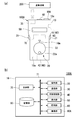
- FIG. 1A is a diagram illustrating an example of the operation terminal 100 according to the present embodiment.
- FIG. 1B is a block diagram illustrating an example of the operation terminal 100.
- the operation terminal 100 is a portable operation terminal that can perform wireless communication with the industrial machine 200 (see FIG. 1A) and can operate the industrial machine 200 through the wireless communication.
- Examples of the industrial machine 200 include a machine tool that processes a predetermined workpiece.
- the industrial machine 200 includes, for example, a loader device that transports a workpiece, a processing device that cuts the workpiece, an operation panel that directly operates the industrial machine 200, a control device that comprehensively controls the industrial machine 200, and the like.
- the operation terminal 100 has a terminal body 10 formed in a size and shape that can be held by an operator with one hand.
- the terminal body 10 includes an operation unit 20, a communication unit 30, an external connection unit 40, a display unit 50, a lighting unit 60, a control unit 70, and a storage unit 80.
- the terminal body 10 is provided with a power supply unit (not shown) that supplies power to each unit.
- the power supply unit may be a built-in type or an external type.
- the operation unit 20 selects the operation part of the terminal body 10 and the industrial machine 200 to be operated, and operates the selected operation part.
- the operation unit 20 includes a button 21 and a dial 22.
- the buttons 21 are provided on the left and right side surfaces of the terminal body 10.
- the button 21 can be operated with the hand of the operator holding the terminal body 10, for example.
- the button 21 includes an operation mode (hereinafter referred to as a first mode) for selecting an operation part of the terminal body 10 and the industrial machine 200 to be operated, and an operation mode (hereinafter referred to as a second mode) for operating the selected operation part. Switch to mode.)
- the dial 22 is disposed on the front surface 10 a of the terminal body 10.
- the dial 22 can be operated by, for example, the hand of the operator who does not have the terminal body 10.
- the dial 22 is provided with a knob 22a.
- the operator can rotate the dial 22 by holding the knob 22a, for example.
- a scale not shown is formed on the outer periphery of the dial 22.
- an inverted isosceles triangular mark 10 m is formed on the front surface 10 a of the terminal body 10.
- the operator can check the operation amount (rotation amount, rotation angle) of the dial 22. .
- By rotating the dial 22 in the first mode the operation parts of the terminal body 10 and the industrial machine 200 to be selected can be switched. Further, by rotating the dial 22 in the second mode, for example, the movement amount of the selected movement portion can be adjusted.
- a rotary switch or the like may be provided on the front surface of the terminal body 10.
- an operation target can be selected using a rotary switch.
- the communication unit 30 performs wireless communication with an external wireless communication unit.
- the communication unit 30 can transmit and receive various types of information to and from a wireless communication unit (not shown) provided in the industrial machine 200, for example.
- a wireless communication unit for example, a known wireless module is used as the communication unit 30.
- a wireless communication method for example, a method capable of transmitting data such as image information having a size larger than the operation information, such as wireless LAN and optical communication, is adopted.
- the external connection unit (input unit) 40 includes a connector 41 and a card slot 42.
- the connector 41 can be attached to the connection terminal 101 a of the imaging device 101.
- Examples of such an imaging device 101 include a device that can acquire image information. Specific examples include imaging devices such as a microscope and a camera.
- the image information is information related to an image and includes image data such as a still image and a moving image. Further, the image information may include code image data such as a bar code and a two-dimensional code described later.
- the image information includes correction data for correcting the hue, saturation, brightness, distortion, etc. of the image data, and image processing data for performing predetermined processing such as compression processing and restoration processing on the image data. May be included.
- the connector 41 for example, a USB connector or the like is used.
- image information acquired by the imaging device 101 can be input to the connector 41.
- the card slot 42 is loaded with a card-type storage medium such as a memory card.
- an external storage medium that stores the image information is inserted into the card slot 42, the image information stored in the external storage medium is input to the card slot 42.
- the external connection unit 40 is an input unit that can input image information.
- the display unit 50 displays, for example, the names of operation parts of the operation terminal 100 and the industrial machine 200 to be operated. For example, when the dial 22 is rotated in the first mode, the name of the operation part to be selected can be switched and displayed.
- a display device such as a liquid crystal device is used.
- the display unit 50 may be configured to display an image based on image information acquired by the imaging device 101.
- the illumination unit 60 emits illumination light.
- the illumination part 60 is arrange
- a light emitting device such as a high-intensity LED is used.
- the illumination unit 60 may be provided so that the output (brightness) of illumination light can be adjusted. In this case, it is possible to configure the output of the illumination unit 60 to change by rotating the dial 22 with the operation mode of the operation unit 20 being the second mode. In addition, the illumination part 60 may be set so that the output of illumination light may become constant.
- the control unit 70 comprehensively controls the above-described units.
- the control unit 70 has an arithmetic device such as a CPU (Central Processing Unit), and is connected to each unit via a data bus 71.
- a command from the control unit 70, a calculation result by the calculation device of the control unit 70, information read from the storage unit 80, and the like are transmitted to the respective units via the data bus 71.
- the control unit 70 controls an information transmission / reception operation and a wireless communication connection destination in the communication unit 30.
- the control unit 70 can be controlled to transmit the image information input to the external connection unit 40 from the communication unit 30 to the industrial machine 200.
- the control unit 70 may be capable of automatically recognizing a connection destination for wireless communication.
- the control unit 70 can control an external device connected to the external connection unit 40 via the external connection unit 40.
- the control unit 70 can control the display content of the display unit 50, the timing of turning on and off the illumination unit 60, and the like.
- the storage unit 80 stores various types of information such as programs and data used for the control of the control unit 70, for example.
- Information stored in the storage unit 80 includes, for example, information related to the communication destination of the communication unit 30. Examples of the communication destination of the communication unit 30 include the computer (not shown) of a management center that manages the industrial machine 200 in addition to the industrial machine 200. Further, the storage unit 80 stores information about the name of the part to be operated. Note that the image information may be stored in the storage unit 80.
- the control unit 70 can be controlled to transmit the image information stored in the storage unit 80 from the communication unit 30 to the industrial machine 200. In this case, the storage unit 80 functions as an input unit that can input image information.
- connection terminal 101a of the imaging device 101 such as a microscope
- image information of an image captured by the imaging device 101 is Input to the external connection unit 40 (connector 41).
- the control unit 70 can be controlled to transmit the image information input in this way from the communication unit 30 to the industrial machine 200 by wireless communication.
- communication between the terminal body 10 and the industrial machine 200 is wireless communication
- a communication method capable of transmitting and receiving large-sized data can be employed.
- information such as image information different from operation information for operating the industrial machine 200 can be transmitted to the industrial machine 200 quickly and reliably.
- the imaging device 101 since the imaging device 101 is connected to the terminal body 10 provided in a cordless manner to capture an image, there is no restriction on movement due to wiring, for example, a location away from the industrial machine 200 or a location on the back side of the industrial machine 200 Etc., the image can be acquired by moving easily. Moreover, since the imaging device 101 can be removed from the terminal body 10 after the imaging is completed, the burden when the terminal body 10 is carried can be reduced.
- XYZ coordinate system a plane parallel to the horizontal plane is defined as an XZ plane.
- a direction of a main axis (main axes 121 and 122 to be described later) parallel to the XZ plane is expressed as a Z direction
- a direction orthogonal to the Z direction (a direction defining a cutting amount with respect to the workpiece W) is expressed as an X direction.
- the direction perpendicular to the XZ plane is denoted as the Y direction.
- the direction of the arrow in the figure is the + direction
- the direction opposite to the arrow direction is the ⁇ direction.
- FIG. 2 is a diagram illustrating an example of the machine tool system SYS.
- the machine tool system SYS includes an industrial machine 200 and an operation terminal 100 that operates the industrial machine 200.
- FIG. 2 shows an example when the machine tool system SYS is viewed from the + Z side.
- the + Z side of the machine tool system SYS is the front surface
- the ⁇ Z side is the back surface.
- the ⁇ X side of the machine tool system SYS is a side surface
- the X direction is the left-right direction of the machine tool system SYS.
- the industrial machine 200 includes a loader device 110, a machine tool 120, a control device 130, and an operation panel 140.
- the loader device 110 includes a loader head 111 and a loader driving unit 113.
- the loader device 110 conveys the workpiece W between spindles 121 and 122 described later and a workpiece loading unit 125.
- the loader head 111 has a loader chuck 112.
- the loader chuck 112 grips the workpiece W with a plurality of gripping claws.
- the loader chuck 112 is formed so as to be able to move between a posture in which the workpiece W is gripped in the ⁇ Y direction and a posture in the ⁇ Z direction (a posture in which the workpiece W is directed to main shafts 121 and 122 described later). Is done.
- a plurality of loader chucks 112 may be formed in the loader device 110.
- the loader driving unit 113 includes an X driving unit 114, a Z driving unit 115, and a Y driving unit 116.
- the X driving unit 114 includes an X moving body 114a and a guide rail 114b.
- the X moving body 114a is provided so as to be movable in the X direction along the guide rail 114b by a drive source (not shown).
- the Z driving unit 115 is formed on the X moving body 114a.
- the Z driving unit 115 has a Z moving body 115a.
- the Z moving body 115a is provided so as to be movable in the Z direction along a guide portion (not shown) by a drive source (not shown).
- the Y driving unit 116 is formed on the Z moving body 115a.
- the Y driving unit 116 includes a Y moving body 116a.
- the Y moving body 116a is provided so as to be movable in the Y direction along a guide portion (not shown) by
- the loader head 111 is provided below the Y moving body 116a.
- the workpiece W gripped by the loader chuck 112 of the loader head 111 is driven by the X driving unit 114, the Z driving unit 115, and the Y driving unit 116, respectively, so that the X direction, the Y direction, the Z direction, or a combination thereof is combined. Conveyed in the direction.
- the driving of the loader device 110 configured as described above is controlled by the control device 130 described later.
- the machine tool 120 is, for example, a parallel twin-axis lathe.
- the machine tool 120 includes spindles 121 and 122, turrets 123 and 124, and a workpiece carry-in unit 125.
- the main shafts 121 and 122 are arranged side by side in the X direction, and are respectively rotated around the central axes AX1 and AX2 by a driving device (not shown).
- a plurality of grasping claws 121a and 122a capable of gripping the workpiece W are provided at the + Z side ends of the main shafts 121 and 122, respectively.
- the turret 123 is disposed on the ⁇ X side of the main shaft 121.
- the turret 124 is disposed on the + X side of the main shaft 122.
- the turrets 123 and 124 are each rotated about an axis parallel to the Z direction by a driving device (not shown).
- a plurality of cutting tools (not shown) are held on the peripheral surfaces of the turrets 123 and 124, and a desired cutting tool is selected by rotating the turrets 123 and 124.
- a rotating tool such as a drill or an end mill may be used in addition to a cutting tool for cutting the workpiece W.
- the turrets 123 and 124 are movable with respect to the workpiece W in, for example, the X direction and the Z direction by a driving device (not shown).
- the number of the main shafts 121 and 122 and the turrets 123 and 124 is not limited to two. For example, one or both of the main shaft and the turret may be provided.
- the work W to be processed is placed on the work carry-in unit 125.
- a fixed table is used as the workpiece loading unit 125, but the workpiece loading unit 125 is not limited thereto, and a conveyor, a rotary mounting table, or the like may be used.
- the work carry-in part 125 may also serve as a work W carry-out part, and this carry-out part may be arranged in a part different from the work carry-in part 125.
- the driving of the machine tool 120 configured as described above is controlled by the control device 130 described later.
- the control device 130 comprehensively controls operations of the loader device 110 and the machine tool 120 based on a predetermined machining program.
- the control device 130 may be connected to a host control device (not shown) or the like via a wired or wireless connection. In this case, the control device 130 may control the operations of the loader device 110 and the machine tool 120 based on a program stored in the storage unit of the host control device.
- the control device 130 has a setting unit 131.
- the setting unit 131 sets a stop position or a passing position of the loader chuck 112 when teaching the loader device 110 described later.
- the operation panel 140 is an operation device for the industrial machine 200 operated by an operator.
- the operation panel 140 is connected to the control device 130 via a wire or wirelessly.
- the operation panel 140 includes a display unit 141 such as a liquid crystal display and various switches 142.
- the operation panel 140 is used for operations such as program switching and various settings of the control device 130 by an operator, for example.
- an operation terminal 100 shown in FIGS. 1A and 1B is used as a terminal for operating the operation of the industrial machine 200.
- the operation terminal 100 can operate at least one of the loader device 110 and the machine tool 120 by wireless communication.
- the storage unit 80 of the operation terminal 100 stores information on each part of the industrial machine 200 that is the operation target of the operation terminal 100.
- the loader chuck 112, the X drive unit 114, the Z drive unit 115, and the Y drive of the loader device 110 are stored.
- Information such as the part 116 is stored.
- the control device 130 arranges the loader head 111 of the loader device 110 shown in FIG. 2 above (+ Y side) the work loading portion 125, and with the loader chuck 112 facing downward ( ⁇ Y direction), Y
- the moving body 116a is moved in the ⁇ Y direction.
- the control apparatus 130 hold
- the control device 130 orients the loader chuck 112 and the workpiece W in the ⁇ Z direction. Thereafter, the control unit moves the loader head 111 in the + Y direction by the Y driving unit 116 and arranges it at a predetermined height position. Next, the control device 130 moves the loader head 111 in the + X direction to place the loader head 111 and the workpiece W, for example, above the main shaft 121 (+ Y side).
- the loader head 111 and the work W are disposed above the main shaft 122.
- control device 130 moves the Y moving body 116a in the ⁇ Y direction so that the workpiece W faces the main shaft 121. Then, the control device 130 moves the Z moving body 115 a in the ⁇ Z direction and holds the workpiece W on the grasping claw 121 a of the main shaft 121. Thereafter, the Z moving body 115a is moved in the + Z direction and the + Y direction, and the loader head 111 is returned. And the control apparatus 130 processes the workpiece
- the control device 130 causes the loader chuck 112 to deliver the workpiece W from the spindle 121. Specifically, the control device 130 first moves the Y moving body 116 a again in the ⁇ Y direction so that the loader chuck 112 faces the workpiece W. Next, the loader head 111 is moved in the ⁇ Z direction, and the workpiece W is held by the grasping claw of the loader chuck 112. Next, the control device 130 opens the grasping claw 121 a of the spindle 121 and passes the workpiece W to the loader chuck 112.
- the control device 130 After delivering the workpiece W, the control device 130 causes the X driving unit 114, the Z driving unit 115, and the Y driving unit 116 to move the X moving body 114a, the Z moving body 115a, and the Y moving body 116a in the X direction and the Z direction. And the workpiece W is transported to a predetermined transport destination such as a workpiece unloading section (not shown).
- a predetermined transport destination such as a workpiece unloading section (not shown).
- the operator first activates the operation terminal 100 and then selects an operation target by operating the operation mode of the operation unit 20 as the first mode. For example, when the position (first position) P1 at which the loader chuck 112 receives the workpiece W is taught, the operator selects the X driving unit 114, the Z driving unit 115, and the Y driving unit 116 of the loader device 110 in order, and The chuck 112 is manually operated so as to reach the first position P1.
- the control unit 70 instructs the industrial machine 200 so that the X drive unit 114 operates according to the operation of the operation unit 20. Issue a command.
- This command is transmitted to the industrial machine 200 by wireless communication via the communication unit 30.
- the industrial machine 200 receives this command by wireless communication and sets the X drive unit 114 in a state where it can be manually operated.
- the control unit 70 issues a command to adjust the moving amount and moving direction of the X driving unit 114 according to the rotating amount and rotating direction of the dial 22.
- the operator rotates the dial 22 clockwise.
- the operator turns the dial 22 counterclockwise.
- the setting is made in advance such that the rotation is performed.
- the industrial machine 200 receives a command from the control unit 70, the industrial machine 200 controls the X drive unit 114 so that the operation of the command content is performed. The same operation is performed when the Z driving unit 115 and the Y driving unit 116 are controlled, and the loader chuck 112 is moved to the first position P1.
- the operator of the operation terminal 100 or the operator of the industrial machine 200 operates the operation panel 140 and registers the X coordinate, Z coordinate, and Y coordinate of the loader chuck 112 in a storage unit provided in the control device 130. Accordingly, the setting unit 131 sets the coordinates of the first position P1 in the industrial machine 200. Thereafter, by performing manual operation with the operation terminal 100 in the same manner as described above, the setting unit 131, for example, the second position P2 where the loader chuck 112 delivers the workpiece W to the spindle 121 or the third position P3 where the workpiece W is delivered to the spindle 122.
- the position of the loader chuck 112 for each operation is set in the industrial machine 200, such as the position when the work W is carried out, and the position when the work W is reversed by a reversing device (not shown).
- the set information is stored as a data table TB in a storage unit (not shown) provided in the industrial machine 200, for example, as shown in FIG.
- image information captured by the imaging device 101 is transferred to the industrial machine 200 side.
- image information regarding the captured image is input to the external connection unit 40.
- the control unit 70 controls the image information input to the external connection unit 40 to be transmitted from the communication unit 30 to the industrial machine 200 by wireless communication.
- the image information transmission operation may be automatically performed by the control unit 70 or may be performed by the operator operating the operation unit 20.
- the control unit 70 may perform compression processing of transmitted data, image correction processing, and the like.
- the control device 130 can display an image Im based on the image information on the display unit 141 of the operation panel 140 as shown in FIG. 3B, for example. Thereby, the operator can confirm the image Im on the display unit 141.
- the image Im include an image of the workpiece W and an image of the tip of a tool that processes the workpiece W.
- a work held on the main shaft and a cutting tool for cutting the work are shown.
- the image displayed on the display unit 141 may be either a still image or a moving image.
- a moving image for example, a recorded moving image may be displayed, or a moving image being captured may be displayed in a live view.
- this transfer of image information is not limited to when the machining operation of the industrial machine 200 is stopped, but can also be performed when the industrial machine 200 is performing the machining operation.
- the operation terminal 100 can transmit image information to the industrial machine 200 by wireless communication, it can be confirmed on the display unit 141 of the industrial machine 200 remote from the operation terminal 100.
- the operator can illuminate a dark part by the illumination unit 60 of the operation terminal 100.
- the operator sets the operation mode to the first mode and selects the illumination unit 60 as an operation target.
- the control unit 70 controls the illumination unit 60 to emit illumination light.
- the control unit 70 outputs the illumination light output (brightness) of the illumination unit 60 according to the rotation amount of the dial 22. adjust.
- the operation terminal 100 capable of quickly and reliably transmitting image information or the like different from operation information for operating the industrial machine 200 is used. Therefore, a lot of information can be obtained on the industrial machine 200 side. Thereby, operation
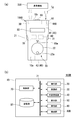
- FIG. 4A illustrates an example of the operation terminal 100A.
- FIG. 4B is a block diagram illustrating an example of the operation terminal 100A.
- the terminal body 10 of the operation terminal 100A includes an operation unit 20, a communication unit 30, an external connection unit 40, a display unit 50, an illumination unit 60,
- an imaging unit 90A is provided.
- the image information is acquired by an imaging device that is one of the imaging devices 101, and the image information is input to the external connection unit 40 by connecting the imaging device to the external connection unit 40.
- image information is input by capturing an image with the imaging unit 90A provided in a part of the operation terminal 100A.
- the control unit 70 can be controlled to transmit the image information acquired by the imaging unit 90 ⁇ / b> A from the communication unit 30 to the industrial machine 200.
- the imaging unit 90A includes a configuration including an imaging element such as a CCD or a CMOS.
- the imaging unit 90A in the terminal body 10, it is possible to save the trouble of attaching and detaching the imaging device 101 to and from the external connection unit 40. Further, since the imaging unit 90A is provided inside the terminal body 10, it is not necessary to carry the imaging device 101 itself, and the operability of the terminal body 10 can be ensured.
- FIG. 5A is a diagram illustrating an example of the operation terminal 100B.
- FIG. 5B is a block diagram illustrating an example of the operation terminal 100B.
- the terminal body 10 of the operation terminal 100B includes an operation unit 20, a communication unit 30, an external connection unit 40, a display unit 50, an illumination unit 60,
- a detection unit 90B is provided.
- the industrial machine 200 will be described by taking a configuration including the loader device 110, the machine tool 120, the control device 130, and the operation panel 140 as an example.
- the detection unit 90B detects an RF signal from an RF (Radio Frequency) tag Tg as an example of an identification unit.
- an RF tag Tg an IC tag, a non-contact IC card, or the like can be used.
- a reader that reads such an RF tag Tg is used as the detection unit 90B.
- the control unit 70 can transmit the RF signal detected by the detection unit 90B as identification information from the communication unit 30 to the industrial machine 200 by wireless communication.
- the RF tag Tg is disposed as a reference position, for example, at a position where the loader device is taught in the teaching operation of the loader device 110 in addition to the first position P1, the second position P2, and the third position P3 of the industrial machine 200. Can do.
- the loader chucks 112 of the loader device 110 are arranged at the teaching positions.
- the operation terminal 100B is brought close to the RF tag Tg provided at the position, and the RF signal is read by the detection unit 90B.
- the control unit 70 transmits identification information based on the read RF signal to the industrial machine 200 side.
- the setting unit 131 uses, based on the received identification information, the X coordinate, the Z coordinate, and the Y coordinate of the loader chuck 112 arranged at each teaching position as the coordinates of the position where the RF tag Tg is provided. Set in association. Thereby, the operator can save the trouble of moving the operation panel 140 to register the coordinates after arranging the loader chuck 112 at each teaching position.
- the terminal main body 10 is formed in a cordless shape, the terminal main body 10 can be moved freely according to the position of the RF tag Tg to read the RF signal.
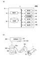
- FIG. 6A is a block diagram illustrating an example of the operation terminal 100C.
- FIG. 6B is a diagram illustrating an example of how the operation terminal 100C is used.
- the terminal body 10 of the operation terminal 100C includes an operation unit 20, a communication unit 30, an external connection unit 40, a display unit 50, an illumination unit 60, a control unit 70, In addition to the storage unit 80, a detection unit 90C is provided. Note that the appearance of the operation terminal 100C is substantially the same as that of the operation terminal 100 shown in FIG. Further, in the present modification, a configuration including the loader device 110, the machine tool 120, the control device 130, and the operation panel 140 as the industrial machine 200 will be described as an example.
- the detection unit 90C detects code information of a code part such as a barcode or a two-dimensional code as an identification part.
- a connection terminal 102a of a code detection device 102 such as a barcode scanner or a two-dimensional code scanner is attached to the external connection unit 40 (connector 41) of the operation terminal 100C.
- FIG. 6B shows an example in which the code detection device 102 detects a barcode (identification unit) Tc provided on the cutting tool T.
- the cutting tool T is used for cutting the workpiece W, for example, in the industrial machine 200 of the above embodiment.
- the bar code Tc includes information for managing the cutting tool T, such as the number and types of the cutting tool T used.
- the code detection device 102 detects the barcode Tc and inputs the detected data of the barcode Tc to the external connection unit 40 (connector 41) of the operation terminal 100C.
- the detection unit 90C detects code information from the input detection data.
- the control unit 70 controls the code information detected by the detection unit 90C to be transmitted from the communication unit 30 to the industrial machine 200 by wireless communication.
- the control device 130 detects information about the cutting tool T based on the received code information. Based on the detected information, the control device 130 may display the number and type of cutting tools T used on the display unit 141 of the operation panel 140. In this case, it is possible to easily manage the number and types of cutting tools T used.
- such a barcode may be given to the workpiece W as information such as the shape and dimensions of the workpiece W, for example.
- the control device 130 detects information about the workpiece W to be processed based on the code information received from the operation terminal 100C.
- the control device 130 can switch and control a machining program, a tool shift pattern, a production number, and the like according to the detected information.
- Such bar code detection by the code detection device 102 may be performed, for example, at the start of work inspection. Further, the present invention is not limited to the case where a barcode is detected by the code detection device 102.
- the barcode may be captured by the imaging device 101 described above.
- the control unit 70 transmits barcode image information to the industrial machine 200 via the communication unit 30.
- the code information is read based on the image information of the barcode, and information about the cutting tool T, the workpiece W, and the like may be detected based on the code information.
- the function of the code detection device 102 may be incorporated in the operation terminal 100C.
- the operation terminal 100C includes the detection unit 90C that detects code information
- code information such as a barcode and a two-dimensional code can be transmitted to the industrial machine 200.
- a bar code or the like is given to the cutting tool T or the workpiece W, and the bar code information is transmitted from the operation terminal 100C to the industrial machine 200 that transfers the bar code. It is possible to more efficiently manage the processing operation and the like of T and the workpiece W.
- the operation terminal 100 itself can be used as a storage medium.
- information can be transferred by storing predetermined information in the storage unit 80 of the operation terminal 100 and transmitting the predetermined information by wireless communication.
- the part for storing the predetermined information is not limited to the storage unit 80.
- a memory card or the like may be inserted into the card slot 42 and the predetermined information may be stored in the memory card.
- the predetermined information stored in the storage unit 80 or the memory card includes, for example, a machining program for the workpiece W.
- a machining program for the workpiece W for example, a machining program for the workpiece W.
- FIGS. 7A and 7B are diagrams illustrating an example of how the operation terminal 100 is used.
- the operator moves to the management center with the operation terminal 100, and makes the wireless communication between the operation terminal 100 and the computer 300 as shown in FIG.
- the operator transmits information such as a machining program from the computer 300 to the operation terminal 100 via the wireless communication.
- This information is received via the communication unit 30 and stored in the storage unit 80.
- the control unit 70 can control the connection destination of wireless communication by performing authentication using a password or the like.
- the information of the computer 300 is stored in the storage unit 80, it may be performed via wired communication. Alternatively, information may be exchanged by inserting a memory card into the computer 300 to store information and inserting the memory card into the card slot 42 of the operation terminal 100.
- the operator carries the operation terminal 100 to the vicinity of the industrial machine 200 and activates the operation terminal 100.
- the control unit 70 recognizes the industrial machine 200 as a wireless communication connection destination, the control unit 70 switches the connection destination setting from the computer 300 to the industrial machine 200, and Wireless communication is performed with.
- the wireless communication connection destination may be switched by an operator's operation.
- control unit 70 causes the industrial machine 200 to transmit information such as a machining program stored in the storage unit 80 by the operation of the operator.
- control device 130 controls the operations of the loader device 110, the machine tool 120, and the like based on the received information such as the machining program.
- the operation terminal 100 can communicate large-sized information by wireless communication, the operation terminal 100 can be used as a storage medium.
- a storage medium such as a USB memory
- this modification such information can be easily exchanged, so that the convenience of the industrial machine system is improved.
- the technical scope of the present invention is not limited to the above-described embodiment, and appropriate modifications can be made without departing from the spirit of the present invention.
- a configuration having the loader device 110, the machine tool 120, the control device 130, and the operation panel 140 as the industrial machine 200 has been described as an example.
- the present invention is not limited to this.
- the loader device 110 alone or the machine tool 120 alone may be used.
- the industrial machine 200 is not limited to these configurations, and may be another industrial machine such as a robot.
- loader drive unit 114 ... X drive unit 115 ... Z drive unit 116 ... Y drive unit 120 ... machine tool 121, 122 ... spindle 130 ... control device 131 ... setting unit 200 ... industrial machine 3 0 ... computer
Landscapes
- Engineering & Computer Science (AREA)
- Physics & Mathematics (AREA)
- General Physics & Mathematics (AREA)
- Computer Networks & Wireless Communication (AREA)
- Human Computer Interaction (AREA)
- Manufacturing & Machinery (AREA)
- Automation & Control Theory (AREA)
- Numerical Control (AREA)
Abstract
Description
操作端末100は、産業機械200(図1(a)参照)との間で無線通信が可能であり、この無線通信によって産業機械200を操作可能な携帯型の操作端末である。産業機械200としては、例えば所定のワークに対して加工を行う工作機械などが挙げられる。産業機械200は、例えばワークを搬送するローダ装置や、ワークを切削する加工装置、産業機械200を直接操作する操作パネル、産業機械200を統括的に制御する制御装置等を有している。
次に、工作機械システムSYSについて説明する。以下、XYZ座標系を用いて図中の方向を説明する。このXYZ座標系においては、水平面に平行な平面をXZ平面とする。このXZ平面に平行な主軸(後述する主軸121、122)の方向をZ方向と表記し、Z方向に直交する方向(ワークWに対する切削量を規定する方向)をX方向と表記する。また、XZ平面に垂直な方向はY方向と表記する。X方向、Y方向及びZ方向のそれぞれは、図中の矢印の方向が+方向であり、矢印の方向とは反対の方向が-方向であるものとして説明する。
次に、変形例を説明する。図4(a)は、操作端末100Aの一例を示す図である。図4(b)は、操作端末100Aの一例を示すブロック図である。図4(a)及び(b)に示すように、本変形例では、操作端末100Aの端末本体10には、操作部20、通信部30、外部接続部40、表示部50、照明部60、制御部70、及び記憶部80に加えて、撮像部90Aが設けられている。
例えば、上記説明では、産業機械200として、ローダ装置110、工作機械120、制御装置130及び操作パネル140を有する構成を例に挙げて説明したが、これに限定するものではない。例えば、産業機械として、ローダ装置110単独であってもよいし、工作機械120単独であってもよい。また、産業機械200として、これらの構成に限られず、ロボット等他の産業機械であってもよい。
Claims (7)
- 産業機械を無線通信により操作可能な携帯型の操作端末であって、
端末本体を備え、
前記端末本体は、画像に関する画像情報を入力可能な入力部と、
前記入力部に入力された前記画像情報を伝送可能な通信部と、を備える操作端末。 - 前記端末本体は、前記画像情報を撮像する撮像部を備える請求項1記載の操作端末。
- 前記端末本体は、前記画像情報に基づく画像を表示する表示部を備える請求項1または請求項2記載の操作端末。
- 前記端末本体は、照明光を射出する照明部を備える請求項1~請求項3のいずれか1項に記載の操作端末。
- 産業機械を無線通信により操作可能な携帯型の操作端末であって、
所定位置に配置される識別部の情報を検出する検出部と、
前記検出部で検出した情報を伝送可能な通信部と、を備える操作端末。 - ワークを加工する工作機械と、
前記ワークを支持するワーク支持部が移動して前記工作機械に対して前記ワークの搬入及び搬出を行うローダ装置と、
前記ワーク支持部が移動可能な前記工作機械の基準位置に配置された識別部と、
前記工作機械及び前記ローダ装置の少なくとも一方を無線通信により操作可能であり、前記識別部の識別情報を検出する検出部、及び前記検出部で検出した前記識別情報を伝送する通信部を備える携帯型の操作端末と、
前記通信部から伝送された前記識別情報により認識した前記ワーク支持部の位置情報に基づいて前記ワーク支持部の停止位置または通過位置を設定する設定部と、を備える工作機械システム。 - 携帯型の操作端末を用いて無線通信により産業機械を操作する方法であって、
画像に関する画像情報を前記操作端末に入力することまたは所定位置に配置される識別部の情報を前記操作端末により検出することと、
入力した画像情報または検出した前記識別部の情報を前記操作端末から伝送することと、を含む、産業機械の操作方法。
Priority Applications (3)
| Application Number | Priority Date | Filing Date | Title |
|---|---|---|---|
| CN201580021515.2A CN106255931B (zh) | 2014-06-10 | 2015-05-08 | 机床系统 |
| JP2016527691A JP6187693B2 (ja) | 2014-06-10 | 2015-05-08 | 工作機械システム |
| US15/316,248 US10175675B2 (en) | 2014-06-10 | 2015-05-08 | Machine tool system |
Applications Claiming Priority (2)
| Application Number | Priority Date | Filing Date | Title |
|---|---|---|---|
| JP2014-119436 | 2014-06-10 | ||
| JP2014119436 | 2014-06-10 |
Publications (2)
| Publication Number | Publication Date |
|---|---|
| WO2015190193A1 true WO2015190193A1 (ja) | 2015-12-17 |
| WO2015190193A8 WO2015190193A8 (ja) | 2016-10-20 |
Family
ID=54833298
Family Applications (1)
| Application Number | Title | Priority Date | Filing Date |
|---|---|---|---|
| PCT/JP2015/063342 Ceased WO2015190193A1 (ja) | 2014-06-10 | 2015-05-08 | 操作端末、工作機械システム、及び産業機械の操作方法 |
Country Status (4)
| Country | Link |
|---|---|
| US (1) | US10175675B2 (ja) |
| JP (1) | JP6187693B2 (ja) |
| CN (1) | CN106255931B (ja) |
| WO (1) | WO2015190193A1 (ja) |
Cited By (3)
| Publication number | Priority date | Publication date | Assignee | Title |
|---|---|---|---|---|
| JP2017227948A (ja) * | 2016-06-20 | 2017-12-28 | キタムラ機械株式会社 | 工作機械用nc機能付操作盤 |
| WO2022019263A1 (ja) * | 2020-07-22 | 2022-01-27 | ファナック株式会社 | ロボット制御システム |
| JP2023524737A (ja) * | 2020-05-06 | 2023-06-13 | セコ ツールズ アクティエボラーグ | 生産工程に関連する二酸化炭素フットプリントを削減するための方法、電子デバイス、およびコンピュータプログラム製品 |
Families Citing this family (1)
| Publication number | Priority date | Publication date | Assignee | Title |
|---|---|---|---|---|
| JP6374467B2 (ja) * | 2016-11-14 | 2018-08-15 | ファナック株式会社 | 通信システムおよび携帯端末 |
Citations (5)
| Publication number | Priority date | Publication date | Assignee | Title |
|---|---|---|---|---|
| JP2001158507A (ja) * | 1999-09-21 | 2001-06-12 | Shinko Electric Co Ltd | ストッカ用ロボットの教示方法、ストッカ用ロボットの教示装置及び記録媒体 |
| JP2002312011A (ja) * | 2001-04-10 | 2002-10-25 | Enshu Ltd | 工作機械のための情報通信システム |
| JP2006341957A (ja) * | 2005-06-09 | 2006-12-21 | National Institute Of Advanced Industrial & Technology | 物品分類収納システム及びマニピュレーションシステム |
| WO2013094366A1 (ja) * | 2011-12-22 | 2013-06-27 | 村田機械株式会社 | 産業機械システムおよび産業機械システム用情報処理機器 |
| JP2014065100A (ja) * | 2012-09-25 | 2014-04-17 | Denso Wave Inc | ロボットシステム、及びロボットのティーチング方法 |
Family Cites Families (13)
| Publication number | Priority date | Publication date | Assignee | Title |
|---|---|---|---|---|
| JPH07251391A (ja) * | 1994-03-16 | 1995-10-03 | Tokico Ltd | 工業用ロボット |
| JP2003085267A (ja) * | 2001-09-10 | 2003-03-20 | Shin Caterpillar Mitsubishi Ltd | 作業機械の機体管理システム |
| JP4911365B2 (ja) * | 2005-03-18 | 2012-04-04 | 株式会社安川電機 | ロボットに用いるティーチングボックスおよびカスタマイズ方法とこれらを用いたロボットシステム |
| JP2008545546A (ja) * | 2005-06-10 | 2008-12-18 | プロトタイプ・プロダクションズ・インコーポレーテッド | 閉ループcnc機械加工システムおよびその方法 |
| JP4221014B2 (ja) * | 2006-06-20 | 2009-02-12 | ファナック株式会社 | ロボット制御装置 |
| US20080058993A1 (en) * | 2006-09-05 | 2008-03-06 | Okuma America Corporation | System, Methods, Apparatuses and Computer Program Products for Use on a Machine Tool Controller |
| TWI400591B (zh) * | 2010-03-12 | 2013-07-01 | Ind Tech Res Inst | 具有線上振動偵測調控之工具機 |
| SG194940A1 (en) * | 2011-05-13 | 2013-12-30 | Furmanite Australia | Surface machining apparatus |
| JP5565392B2 (ja) * | 2011-08-11 | 2014-08-06 | 株式会社安川電機 | 携帯遠隔操作装置およびロボットシステム |
| US9292811B2 (en) * | 2012-11-30 | 2016-03-22 | Proper Group International | System and method for automated tool management |
| JP2013222381A (ja) | 2012-04-18 | 2013-10-28 | Murata Mach Ltd | ハンディ型操作装置 |
| CN103049774B (zh) * | 2012-12-14 | 2015-07-22 | 华中科技大学 | 一种对模具加工过程的运动对象实现自动定位的方法 |
| JP2014155578A (ja) * | 2013-02-15 | 2014-08-28 | Brother Ind Ltd | 撮影装置のコントローラに実行させるためのプログラム、ミシンシステム及び刺繍枠 |
-
2015
- 2015-05-08 CN CN201580021515.2A patent/CN106255931B/zh active Active
- 2015-05-08 JP JP2016527691A patent/JP6187693B2/ja active Active
- 2015-05-08 WO PCT/JP2015/063342 patent/WO2015190193A1/ja not_active Ceased
- 2015-05-08 US US15/316,248 patent/US10175675B2/en active Active
Patent Citations (5)
| Publication number | Priority date | Publication date | Assignee | Title |
|---|---|---|---|---|
| JP2001158507A (ja) * | 1999-09-21 | 2001-06-12 | Shinko Electric Co Ltd | ストッカ用ロボットの教示方法、ストッカ用ロボットの教示装置及び記録媒体 |
| JP2002312011A (ja) * | 2001-04-10 | 2002-10-25 | Enshu Ltd | 工作機械のための情報通信システム |
| JP2006341957A (ja) * | 2005-06-09 | 2006-12-21 | National Institute Of Advanced Industrial & Technology | 物品分類収納システム及びマニピュレーションシステム |
| WO2013094366A1 (ja) * | 2011-12-22 | 2013-06-27 | 村田機械株式会社 | 産業機械システムおよび産業機械システム用情報処理機器 |
| JP2014065100A (ja) * | 2012-09-25 | 2014-04-17 | Denso Wave Inc | ロボットシステム、及びロボットのティーチング方法 |
Cited By (11)
| Publication number | Priority date | Publication date | Assignee | Title |
|---|---|---|---|---|
| JP2017227948A (ja) * | 2016-06-20 | 2017-12-28 | キタムラ機械株式会社 | 工作機械用nc機能付操作盤 |
| WO2017221827A1 (ja) * | 2016-06-20 | 2017-12-28 | キタムラ機械株式会社 | 工作機械用nc機能付操作盤 |
| US10691105B2 (en) | 2016-06-20 | 2020-06-23 | Kitamura Machinery Co., Ltd. | Control panel having NC function for machine tool |
| TWI702482B (zh) * | 2016-06-20 | 2020-08-21 | 日商北村機械股份有限公司 | 附有工作機械用nc功能之操作面板 |
| JP2023524737A (ja) * | 2020-05-06 | 2023-06-13 | セコ ツールズ アクティエボラーグ | 生産工程に関連する二酸化炭素フットプリントを削減するための方法、電子デバイス、およびコンピュータプログラム製品 |
| JP7774577B2 (ja) | 2020-05-06 | 2025-11-21 | セコ ツールズ アクティエボラーグ | 生産工程に関連する二酸化炭素フットプリントを削減するための方法、電子デバイス、およびコンピュータプログラム製品 |
| WO2022019263A1 (ja) * | 2020-07-22 | 2022-01-27 | ファナック株式会社 | ロボット制御システム |
| JPWO2022019263A1 (ja) * | 2020-07-22 | 2022-01-27 | ||
| CN115943022A (zh) * | 2020-07-22 | 2023-04-07 | 发那科株式会社 | 机器人控制系统 |
| JP7513719B2 (ja) | 2020-07-22 | 2024-07-09 | ファナック株式会社 | ロボット制御システム |
| DE112021002748B4 (de) | 2020-07-22 | 2026-04-16 | Fanuc Corporation | Robotersteuersystem |
Also Published As
| Publication number | Publication date |
|---|---|
| JPWO2015190193A1 (ja) | 2017-04-20 |
| WO2015190193A8 (ja) | 2016-10-20 |
| US20170139397A1 (en) | 2017-05-18 |
| CN106255931A (zh) | 2016-12-21 |
| CN106255931B (zh) | 2019-11-29 |
| JP6187693B2 (ja) | 2017-08-30 |
| US10175675B2 (en) | 2019-01-08 |
Similar Documents
| Publication | Publication Date | Title |
|---|---|---|
| JP6187693B2 (ja) | 工作機械システム | |
| US9158299B2 (en) | Robot system and method for producing to-be-worked material | |
| US10293499B2 (en) | Movable robot | |
| JP2006035397A (ja) | 搬送ロボットシステム | |
| JP6873592B2 (ja) | 操作部材及び産業機械システム | |
| CN116133788B (zh) | 搬送系统、搬送系统的控制方法以及搬送系统的控制程序 | |
| JP2015233223A (ja) | 操作端末及び産業機械システム | |
| JPWO2018163242A1 (ja) | 画像処理データ作成用のデータ構造および画像処理データ作成方法 | |
| JPWO2015063828A1 (ja) | 加工機械および加工機械ライン | |
| US20180086592A1 (en) | Feeder arrangement support system and method for supporting feeder arrangement | |
| JP7221299B2 (ja) | 対基板作業機の機器管理システム | |
| KR102547332B1 (ko) | 제어 시스템 및 실장 장치 | |
| JP6414317B2 (ja) | 産業機械システム | |
| JP4640731B2 (ja) | 切削装置オペレーションシステム | |
| WO2014128884A1 (ja) | 通信システム及び電子部品装着装置 | |
| JP2011023501A (ja) | パーツフィーダ | |
| JP2015233224A (ja) | 操作端末及び産業機械システム | |
| JP6477052B2 (ja) | 産業機械システム、及び情報供給方法 | |
| JPWO2015015567A1 (ja) | 生産設備 | |
| CN117356176A (zh) | 作业装置 | |
| WO2018011998A1 (ja) | 携帯端末、電子部品実装システム、および部品供給部材 | |
| US20200257272A1 (en) | Machining tool apparatus | |
| JP2015182211A (ja) | ロボットシステム、ロボット、制御装置、及び制御方法 | |
| JP7295702B2 (ja) | 通信システム | |
| JP2023138647A (ja) | 部品装着システム |
Legal Events
| Date | Code | Title | Description |
|---|---|---|---|
| 121 | Ep: the epo has been informed by wipo that ep was designated in this application |
Ref document number: 15806514 Country of ref document: EP Kind code of ref document: A1 |
|
| ENP | Entry into the national phase |
Ref document number: 2016527691 Country of ref document: JP Kind code of ref document: A |
|
| WWE | Wipo information: entry into national phase |
Ref document number: 15316248 Country of ref document: US |
|
| NENP | Non-entry into the national phase |
Ref country code: DE |
|
| 122 | Ep: pct application non-entry in european phase |
Ref document number: 15806514 Country of ref document: EP Kind code of ref document: A1 |