WO2015189905A1 - 平角線ステータコイルの製造方法 - Google Patents
平角線ステータコイルの製造方法 Download PDFInfo
- Publication number
- WO2015189905A1 WO2015189905A1 PCT/JP2014/065276 JP2014065276W WO2015189905A1 WO 2015189905 A1 WO2015189905 A1 WO 2015189905A1 JP 2014065276 W JP2014065276 W JP 2014065276W WO 2015189905 A1 WO2015189905 A1 WO 2015189905A1
- Authority
- WO
- WIPO (PCT)
- Prior art keywords
- flat wire
- rectangular
- flat
- wire
- stator coil
- Prior art date
Links
Images


Classifications
-
- H—ELECTRICITY
- H02—GENERATION; CONVERSION OR DISTRIBUTION OF ELECTRIC POWER
- H02K—DYNAMO-ELECTRIC MACHINES
- H02K15/00—Methods or apparatus specially adapted for manufacturing, assembling, maintaining or repairing of dynamo-electric machines
- H02K15/08—Forming windings by laying conductors into or around core parts
- H02K15/085—Forming windings by laying conductors into or around core parts by laying conductors into slotted stators
-
- H—ELECTRICITY
- H02—GENERATION; CONVERSION OR DISTRIBUTION OF ELECTRIC POWER
- H02K—DYNAMO-ELECTRIC MACHINES
- H02K15/00—Methods or apparatus specially adapted for manufacturing, assembling, maintaining or repairing of dynamo-electric machines
- H02K15/0056—Manufacturing winding connections
- H02K15/0068—Connecting winding sections; Forming leads; Connecting leads to terminals
- H02K15/0081—Connecting winding sections; Forming leads; Connecting leads to terminals for form-wound windings
-
- H—ELECTRICITY
- H02—GENERATION; CONVERSION OR DISTRIBUTION OF ELECTRIC POWER
- H02K—DYNAMO-ELECTRIC MACHINES
- H02K15/00—Methods or apparatus specially adapted for manufacturing, assembling, maintaining or repairing of dynamo-electric machines
- H02K15/04—Methods or apparatus specially adapted for manufacturing, assembling, maintaining or repairing of dynamo-electric machines of windings, prior to mounting into machines
- H02K15/0414—Windings consisting of separate elements, e.g. bars, hairpins, segments, half coils
- H02K15/0421—Windings consisting of separate elements, e.g. bars, hairpins, segments, half coils consisting of single conductors, e.g. hairpins
-
- H—ELECTRICITY
- H02—GENERATION; CONVERSION OR DISTRIBUTION OF ELECTRIC POWER
- H02K—DYNAMO-ELECTRIC MACHINES
- H02K15/00—Methods or apparatus specially adapted for manufacturing, assembling, maintaining or repairing of dynamo-electric machines
- H02K15/06—Embedding prefabricated windings in machines
- H02K15/062—Windings in slots; salient pole windings
- H02K15/064—Windings consisting of separate segments, e.g. hairpin windings
-
- H—ELECTRICITY
- H02—GENERATION; CONVERSION OR DISTRIBUTION OF ELECTRIC POWER
- H02K—DYNAMO-ELECTRIC MACHINES
- H02K3/00—Details of windings
- H02K3/04—Windings characterised by the conductor shape, form or construction, e.g. with bar conductors
- H02K3/12—Windings characterised by the conductor shape, form or construction, e.g. with bar conductors arranged in slots
Definitions
- the present invention relates to a method of manufacturing a rectangular stator coil used for an electric motor or the like.
- a stator coil such as an electric motor is wound around a cylindrical stator core.
- the stator core includes a plurality of teeth on the inner periphery at equal angular intervals.
- a slot is formed between adjacent teeth.
- the wire constituting the coil is wound around the teeth through a pair of slots formed with one or more teeth interposed therebetween.
- the wire wound around the teeth protrudes from the end face of the stator core in the axial direction between the pair of slots.
- the coil is a coil that passes through another slot. It intersects the motor axis direction. Crossing takes place at the coil end. The number of intersections depends on the winding pitch of the coil, i.e., how many teeth the winding takes over, and the number of intersections increases with the number of winding pitches.
- Coil end crossing increases the coil end projection length in the axial direction from the end surface of the stator core.
- the crossed coil end conductors are meshed. Weaving was done.
- JP2010-166803A issued by the Japan Patent Office in 2010 is a method of winding a coil by fitting a wire assembly in which a plurality of wires are coiled into a pair of slots. It has been proposed to form a step in the axial direction at the coil end in advance by performing a wire and providing a crank portion at the coil end of the wire assembly.
- This prior art facilitates the crossing of coil ends by passing a conductor assembly of another adjacent coil through a space created by a step between the coil ends between the coil end and the end face of the stator core.
- the protruding length in the axial direction of the coil end is inevitable as the number of intersections between the coil and other coils, in other words, the number of winding pitches increases.
- the formation of the step makes it easy to handle the intersection, but the work load of winding the preformed wire around the teeth of the stator core is still not reduced.
- an object of the present invention is to suppress the axial projecting length of the coil end and reduce the work load of the coil winding with respect to the winding of the stator coil.
- the present invention provides a first end surface, a second end surface, a plurality of teeth extending between the first end surface and the second end surface, and an adjacent tooth.
- the present invention is applied to a method of manufacturing a rectangular stator coil in which a rectangular wire is wound around a stator core having a formed slot.
- a rectangular wire element formed in a substantially U-shape is inserted into each pair of slots from the first end face, and each end portion of the flat wire element protrudes from the second end face, and protrudes from the second end face.
- a plurality of rectangular wire pieces forming a stator coil by connecting between predetermined ends of the rectangular wire elements to be formed in advance as a subassembly, the subassembly being disposed on the second end surface, and the rectangular wire pieces of the subassembly. Are joined between predetermined end portions of the flat wire element protruding from the second end face.
- FIG. 1A and 1B are a perspective view of a stator coil manufactured by a method for manufacturing a rectangular stator coil according to a first embodiment of the present invention, and an enlarged perspective view of a main part.
- FIG. 2 is a cross-sectional view of a main part of a rectangular stator coil.
- FIG. 3 is a side view of the main part of the rectangular wire element and the rectangular wire piece constituting the rectangular wire stator coil as viewed from the center direction of the stator core.
- FIG. 4 is a front view of a main part of the rectangular wire element and the rectangular wire piece as viewed from the axial direction of the stator.
- FIG. 5 is a perspective view of the outer rectangular wire element.
- FIG. 6 is a side view of the main part of the flat wire element for one row inserted into the stator core as viewed from the center direction of the stator core.
- FIG. 7 is a front view of a main part of the rectangular wire elements for one row inserted into the stator core as viewed from the axial direction of the stator core.
- FIG. 8 is a perspective view of the inner rectangular wire element.
- FIG. 9 is a perspective view of the inner rectangular wire unit in which the inner rectangular wire elements for two rows are assembled.
- FIG. 10 is a perspective view of the outer rectangular wire unit in which the outer rectangular wire elements for two rows are assembled.
- FIG. 11 is a perspective view of a rectangular wire unit that combines an inner rectangular wire unit and an outer rectangular wire unit.
- FIG. 12 is a perspective view of the stator core.
- FIG. 13 is a perspective view of the outer rectangular wire unit inserted in the stator core.
- FIG. 14 is a perspective view of a sub-assembly using a plurality of rectangular wire pieces.
- FIG. 15 is a perspective view of a connected state of the flat wire element and the flat wire piece.
- FIG. 16 is a plan view of a connecting portion between a flat wire element and a flat wire piece.
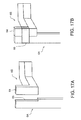
- FIG. 17A and 17B are perspective views of a connecting portion of a flat wire element and a flat wire piece according to the second embodiment of the present invention.
- FIG. 18A and 18B are perspective views of a connecting portion of a flat wire element and a flat wire piece according to the third embodiment of the present invention.
- FIG. 19A and 19B are perspective views of a connecting portion of a flat wire element and a flat wire piece according to the fourth embodiment of the present invention.
- FIG. 20A to 20C are perspective views of a connecting portion of the flat wire element and the flat wire piece, explaining variations regarding the shape of the flat wire element and the flat wire piece.
- FIG. 21A-21C are perspective views of the connecting portion of the flat wire element and the flat wire piece, explaining the positional relationship with the joint portion.
- FIG. 22A to 22C are perspective views of two connecting portions adjacent to each other between the flat wire element and the flat wire piece, showing the arrangement of the insulating material.
- FIG. 23 is a side view of the stator core and the subassembly showing the arrangement of the cooling passages.
- FIG. 24 is a side view of the data core and the subassembly showing the arrangement of the radiation fins.
- FIG. 25 is a vertical cross-sectional view of the main part of the subassembly for explaining variations regarding the shape of the gap formed in the subassembly.
- FIG. 1A and 1B, FIG. 2-7, and FIG. 12 the basic structure of a rectangular stator coil to which the present invention is applied will be described.
- a stator 1 used in an electric motor or the like includes a plurality of sets of coils 3 formed by winding a rectangular wire 6 around a cylindrical stator core 2.
- the flat wire 6 is composed of a conductive wire in which an insulating material is coated on the outer periphery of the copper wire.
- the stator core 2 includes a first end surface 2A and a second end surface 2B in the axial direction. Teeth 4 are formed at equal angular intervals on the inner periphery of the stator core 2. A slot 5 through which the flat wire 6 is inserted is formed between the teeth 4. The slots 5 open to the inner peripheral surface of the stator core 2, the first end surface 2A, and the second end surface 2B, respectively.
- the coil 3 is composed of a flat wire 6 wound around a pair of slots 5 straddling five teeth 4 over four turns, as indicated by oblique lines in the figure. In this way, the flat wire 6 is wound around all the pairs of slots 5 straddling the five teeth 4.
- the plurality of sets of coils 3 attached to the stator core 2 are collectively referred to as a stator coil.
- the rectangular wire 6 constituting each coil 3 includes a rectangular wire element 6A penetrating a predetermined pair of slots 5 of the stator core 2 from the first end surface 2A toward the second end surface 2B, and a second wire 6A.
- the rectangular wire piece 6B is fixed to the end portion of the rectangular wire element 6A that protrudes outward in the axial direction from the end face 2B.
- the flat wire element 6A is configured by cutting the flat wire 6 into a predetermined size in advance and bending it into a substantially U shape by a bending apparatus or the like. A portion corresponding to the bottom of the U-shape is bent at a substantially right angle. The bent portion 61 formed in this way is parallel to the first end face 2A in a state where the rectangular wire element 6A is passed through the stator core 2.
- the rectangular wire element 6A is inserted into the predetermined pair of slots 5 from the first end face 2A. As described above, the rectangular wire 6 is wound around each pair of slots 5 four times. Four rectangular wire elements 6A are inserted into each pair of slots 5.
- FIG. 6 and 7 the bent portion 61 of the flat wire element 6A intersects with the bent portion 61 of the other flat wire element 6A in the motor axial direction on the first end face 2A.
- a step 62 is formed in the bent portion 61.
- the rectangular wire piece 6B is fixed to a rectangular wire element 6A that passes through the slot 5 of the stator core 2 and protrudes from the end surface 2B in the axial direction.
- the rectangular wire piece 6B is composed of a rectangular wire 6 cut short.
- the flat wire piece 6 ⁇ / b> B includes a bent portion 63 similar to the bent portion 61 of the flat wire element 6 ⁇ / b> A and a tip 64 extending in a right angle direction from both ends of the bent portion 63.
- a step 62 similar to that of the bent portion 61 is formed in the bent portion 63.
- Both ends 64 of the flat wire 6B are parallel to the end of the flat wire element 6A in a state in which the bent portion 63 of the flat wire 6B is arranged in parallel to the second cross section of the stator core 2.
- the tip 64 of the flat wire piece 6B formed in this way is held in a state where the end and the side surface of the flat wire element 6A are in contact with each other in the circumferential direction, and the top surfaces of these tips are joined with the weld metal 20.
- the top surfaces of the distal ends are referred to as a joined pair with the distal end 64 of the flat wire piece 6B and the end portion of the flat wire element 6A.
- the flat wire element 6A joined to one end of the flat wire piece 6B and the flat wire element 6A joined to the other end of the flat wire piece 6B are not the same flat wire element 6A.
- the end of the first flat wire element 6A is joined to one end of the flat wire piece 6B, and the other end of the flat wire piece 6B is adjacent to the first flat wire element 6A and passes through the slot 5.
- the ends of the rectangular wire element 6A are joined.
- each of the four rectangular wire pieces 6B is provided at each end of the four rectangular wire elements 6A protruding in the axial direction from the end face 2A.
- the coil 3 is formed by joining the end portions.
- the coil 3 includes four flat wire elements 6A, four flat wire pieces 6B, and eight joint pairs connecting them.
- the distance between the pair of slots 5 penetrating the flat wire element 6A is larger toward the outer peripheral side of the stator core 2 and is smaller at the inner peripheral side.
- the U-shaped width of the flat wire element 6A is narrower in advance as it is arranged closer to the inner side in the radial direction.
- the basic structure of the coil 3 is as described above.
- FIG. A method for manufacturing a rectangular stator coil according to the first embodiment of the present invention will be described below with reference to 14-16.
- FIG. 14 in the method for manufacturing a rectangular stator coil according to the first embodiment of the present invention, all the rectangular wire pieces 6B are arranged in a predetermined overlapping state in advance and integrated using a resin. By fixing the subassembly 7 formed in this way to the stator core 2 in which all the rectangular wire elements 6A are passed through all the slots 5, it is possible to reduce the labor for manufacturing the stator coil.
- the tip 64 of the flat wire piece 6B and the end of the flat wire element 6A protruding in the axial direction from the second end face 2B of the stator core 2 are aligned in the circumferential direction.
- the flat wire piece 6B is previously arranged at a predetermined position and molded using resin.
- the bending direction of the rectangular wire piece 6B is bent outward with respect to the two outer rows and inward with respect to the inner two rows.
- Resin is preferably a heat conductive resin.
- the resin gaps 21 that penetrate the end portions of the flat wire elements 6A are formed between the tips 64 adjacent to each other in the circumferential direction of the flat wire pieces 6B.
- the rectangular wire piece 6B shaped into a predetermined shape is placed inside the mold, and the FIG. 14 is disposed in a predetermined overlapping state as shown in FIG. 14, and a core for the gap 21 is further disposed, and then the resin is poured into the mold. Thereby, the flat wire pieces 6B are fixed to each other by the resin at a predetermined position. Further, by removing the core after the resin is solidified, a gap 21 that penetrates the end portion of the flat wire element 6A is formed between the ends 64 of the flat wire piece 6B refracted outward in the axial direction.
- the sub-assembly 7 formed in this way is attached to the stator core 2 in which all the rectangular wire elements 6A are passed through the slots 5. At this time, the end portion of the rectangular wire element 6 ⁇ / b> A protruding in the axial direction from the second end surface 2 ⁇ / b> B of the stator core 2 is passed through the gap 21 of the subassembly 7.
- FIG. 16 the end of the flat wire element 6A penetrates the gap 21 of the subassembly 7 and protrudes to a position aligned with the tip 64 of the flat wire piece 6B in the circumferential direction.
- FIG. 16 the top surface of the end portion of the flat wire element 6A and the top surface of the tip 64 of the flat wire piece 6B are bonded and fixed.
- the weld metal 20 is deposited so as to straddle both top surfaces from above.
- This joining operation performed between the adjacent rectangular wire element 6A and the rectangular wire piece 6B can be performed in parallel by using, for example, a dedicated joining machine such as a laser welding machine or a brazing machine. is there.
- FIG. As shown in 1A and 1B, the winding of all the coils 3 is completed.
- stator 1 In order to reduce the labor of winding the coil 3, it is also easy to manufacture the stator 1 by assembling the rectangular wire element 6A in advance as a unit as described below and inserting it into the stator core 2 as a unit at a time. In addition, it is preferable.
- FIG. 9 two inner windings of the rectangular wire element 6 ⁇ / b> A that overlap in the radial direction in the slot 5 are assembled as an inner rectangular wire unit 11 using the rectangular wire element 6 ⁇ / b> A.
- FIG. 10 Referring to FIG. 10, the two outer volumes are shown in FIG. 5 is assembled as an outer rectangular wire unit 12 using a rectangular wire element 6A shown in FIG.
- FIG. 10 Referring to FIG. 11, all of the four rows of rectangular wire elements 6 ⁇ / b> A are formed as one rectangular wire unit by inserting the inner rectangular wire unit 11 from the axial direction inside the outer rectangular wire unit 12 assembled in this way. It will be in the assembled state. The rectangular wire unit is inserted into the slot 5 of the stator core 2 at a time.
- FIG. 13 it is also possible to pass only the outer rectangular unit 12 through the slot 5 first, and then penetrate the inner rectangular unit 11 into the slot 5 inside the outer rectangular unit 12. .
- the bent portion 61 of the flat wire element 6A is also preferable to reverse the bending direction of the bent portion 61 of the flat wire element 6A between the inner flat wire unit 11 and the outer flat wire unit 12. That is, the bent portion 61 of the inner rectangular wire unit 11 is bent inward in the radial direction, and the bent portion 61 of the outer rectangular wire unit 12 is bent outward in the radial direction.
- the bent portion 61 of the inner rectangular wire unit 11 and the outer rectangular wire unit 12 are connected to the motor. Since it does not cross in the axial direction, the length of the coil end protruding in the axial direction by the flat wire element 6A can be further reduced.
- the labor of winding the coil 3 is reduced. can do. Further, the axial length of one coil end of the stator coil is reduced by the bent portion 63 of the flat wire piece 6B, and the axial length of the other coil end of the stator coil is reduced by the bent portion 61 of the flat wire element 6A. It is also reduced.
- the number of overlaps of the bent portions 63 can be reduced by configuring the bent portions 63 of the flat wire pieces 6B with outer and inner bent portions in the radial direction.
- the heat dissipation of the coil 3 can be improved.
- FIG. 17A and 17B a method of connecting the flat wire element 6A and the flat wire piece 6B according to the second embodiment of the present invention will be described.
- a notch 65 is formed in advance at the end of the flat wire element 6A. Then, prior to joining the end of the flat wire element 6A and the tip 64 of the flat wire piece 6B, the end of the flat wire element 6A is engaged with the notch 65 of the flat wire piece 6B. And the front-end
- the restraining member 66 is constituted by a tape-like member wound around the end of the flat wire element 6A and the tip 64 of the flat wire piece 6B, the end of the flat wire element 6A and the tip 64 of the flat wire piece 6B are caulked. You may comprise by the member of the rigidity fixed by.
- FIG. 18A and 18B description will be given of a method of connecting the flat wire element 6A and the flat wire piece 6B according to the third embodiment of the present invention.
- a portion of the end of the flat wire element 6A and a portion of the insulating material of the tip 64 of the flat wire piece 6B are cut in advance to form copper wire exposed portions 66 and 67. deep. And in the state which made these adjoin, the edge part of the flat wire element 6A and the front-end
- the FIG. 16 the top surface of the end of the flat wire element 6 ⁇ / b> A and the top surface of the front end of the tip 64 of the flat wire piece 6 ⁇ / b> B are joined using the weld metal 20.
- the restraining member 68 restrains the tip 64 of the flat wire piece 6B and the end of the flat wire element 6A in a close contact state, so that the joint pairs adjacent in the circumferential direction, in other words, between the windings adjacent in the circumferential direction. Therefore, it is possible to prevent an electrical short circuit between the windings of the coil 3.
- the surface of the restraining member 68 that contacts the exposed portions 66 and 67 is made of a conductive material, and the surface exposed to the outside of the restraining member 68 is made of an insulating material. It is also preferable to use the laminated type restraining member 68 configured.
- FIGS. 19A and 19B description will be given of a method of connecting the flat wire element 6A and the flat wire piece 6B according to the fourth embodiment of the present invention.
- a small notch 69 is formed in advance in each of the end of the flat wire element 6A and the tip 64 of the flat wire piece 6B.
- the notch 69 is formed except for a portion where the end of the flat wire element 6A and the tip 64 of the flat wire piece 6B are in contact with each other.
- the end of the flat wire element 6A and the tip 64 of the flat wire piece 6B are in close contact with each other, a gap is secured between adjacent windings. It is possible to prevent electrical short circuit. Further, the amount of use of the restraining member 70 can be reduced as compared with the second and third embodiments. Furthermore, as compared with the second and third embodiments, the restraining member 70 restrains the more distal ends of the flat wire element 6A and the flat wire piece 6B, so that the restraining member 70 can be easily constructed.
- FIG. Similar to the fourth embodiment, small notches 69 are formed in advance at the end of the flat wire element 6A shown in 20A and the tip 64 of the flat wire piece 6B. Such a tip shape is preferable in terms of securing the arrangement space of the member and ensuring heat dissipation regardless of whether or not the restraining member 70 is constructed.
- FIG. A tapered portion 70 is formed in place of the notch 69 at a part of the end portion of the flat wire element 6A shown in 20B and at the tip 64 of the flat wire piece 6B.
- the taper part 70 also brings about a preferable effect similar to the notch 69 in terms of ensuring the arrangement space of members and ensuring heat dissipation.
- FIG. A conical portion 71 is formed in place of the notch 69 at a part of the end portion of the flat wire element 6A shown in 20C and the tip 64 of the flat wire piece 6B. As described above, the conical portion 71 also brings about the same preferable effect as the notch 69 in terms of ensuring the arrangement space of the members and ensuring heat dissipation.
- tip shapes are common in that they are tapered. Even when the tapered tip shape is adopted, a flat top surface 72 is secured at the end of the flat wire element 6A and the tip of the tip 64 of the flat wire piece 6B. The joining of the end of the flat wire element 6A and the front end of the front end 64 of the flat wire piece 6B performed using the weld metal 20 is performed as shown in FIG. As shown in 21A-21C, this is done on these remaining top surfaces 72.
- an insulating material is provided between the small notch 69, the tapered portion 70, or the conical portion 71, and the small notch 69, the tapered portion 70, or the conical portion 71 of the winding adjacent in the circumferential direction. It is also preferable to interpose 73 in order to secure a gap between adjacent windings.
- FIG. 23 it is possible to previously form a cooling passage 75 in the resin portion of the subassembly 7. By circulating the refrigerant in the cooling passage 75, the stator 1 in the operating state can be cooled.
- FIG. 24 when the gap 21 is formed in the subassembly 7, the diameter of the gap 21 can be narrowed outward in the axial direction.
- the axially outer side is FIG. 3 and FIG. Means above 24.
- FIG. 24 the end of the flat wire element 6A penetrates the gap 21 from below to above. If the gap 21 is formed so as to narrow the diameter upward, the gap 21 itself functions as a guide for guiding the end of the flat wire element 6A. Thereby, the end portion of the flat wire element 6A protruding outward in the axial direction from the gap 21 can be accurately positioned.
- the present invention suppresses the protruding length in the axial direction of the coil end of the stator coil and reduces the work load of the coil winding on the stator core. Therefore, for example, a favorable effect can be obtained in downsizing and rationalization of production of an electric motor for vehicles.
Abstract
Description
Claims (10)
- 第1の端面と、第2の端面と、第1の端面と第2の端面との間に延在する複数のティースと、隣接するティース間に形成されたスロットと、を有するステータコアに、スロットを通して平角線を巻線する平角線ステータコイルの製造方法において:
平角線を所定長さに切断して略U字形に折り曲げた複数の平角線エレメントを作成し;
複数の平角線エレメントの所定の端部間を接続することでコイルを形成するように構成された複数の平角線片をあらかじめサブアッセンブリとして成形し;
複数の平角線エレメントの各々を第1の端面から所定の各一対のスロットに挿通し、平角線エレメントの各端部を第2の端面から突出させ;
サブアッセンブリの平角線片を、第2の端面から突出する平角線エレメントの所定の一対の端部に固定することで、サブアッセンブリを第2の端面に装着する、
平角線ステータコイルの製造方法。 - 各平角線エレメントは第1の端面に沿った折り曲げ部を有する、請求項1の平角線ステータコイルの製造方法。
- 各平角線片は第2の端面に沿った折り曲げ部を有する、請求項1または2の平角線ステータコイルの製造方法。
- 平角線片は第2の端面に沿ったラジアル方向外向きの折り曲げ部を有する第1グループの平角線片と、第2の端面に沿ったラジアル方向内向きの折り曲げ部を有する第2グループの平角線片とを有する、請求項3の平角線ステータコイルの製造方法。
- サブアッセンブリは複数の平角線片と、複数の平角線片を所定位置に保持する伝熱性樹脂とを備える、請求項1の平角線ステータコイルの製造方法。
- サブアッセンブリは伝熱性樹脂で構成された部位に冷却材通路をさらに備える、請求項5の平角線ステータコイルの製造方法。
- サブアッセンブリは伝熱性樹脂で構成された放熱部をさらに備える、請求項5の平角線ステータコイルの製造方法。
- 平角線エレメントの端部と平角線片の端部とはともに先細の形状を有する、請求項1の平角線ステータコイルの製造方法。
- 平角線エレメントの端部と平角線片の端部の一方に、もう一方を受け入れる切欠を形成する、請求項1の平角線ステータコイルの製造方法。
- サブアッセンブリの平角線片を、第2の端面から突出する平角線エレメントの所定の一対の端部に固定することは、平角線エレメントの端部とサブアッセンブリの平角線片の先端とを拘束部材で結び合わせることを含む、請求項1の平角線ステータコイルの製造方法。
Priority Applications (5)
| Application Number | Priority Date | Filing Date | Title |
|---|---|---|---|
| CN201480079718.2A CN106471717B (zh) | 2014-06-09 | 2014-06-09 | 扁平线定子线圈的制造方法 |
| US15/316,564 US9825513B2 (en) | 2014-06-09 | 2014-06-09 | Rectangular wire stator coil manufacturing method |
| PCT/JP2014/065276 WO2015189905A1 (ja) | 2014-06-09 | 2014-06-09 | 平角線ステータコイルの製造方法 |
| EP14894810.2A EP3154159B1 (en) | 2014-06-09 | 2014-06-09 | Flat-wire stator coil manufacturing method |
| JP2016527522A JP6260696B2 (ja) | 2014-06-09 | 2014-06-09 | 平角線ステータコイルの製造方法 |
Applications Claiming Priority (1)
| Application Number | Priority Date | Filing Date | Title |
|---|---|---|---|
| PCT/JP2014/065276 WO2015189905A1 (ja) | 2014-06-09 | 2014-06-09 | 平角線ステータコイルの製造方法 |
Publications (1)
| Publication Number | Publication Date |
|---|---|
| WO2015189905A1 true WO2015189905A1 (ja) | 2015-12-17 |
Family
ID=54833037
Family Applications (1)
| Application Number | Title | Priority Date | Filing Date |
|---|---|---|---|
| PCT/JP2014/065276 WO2015189905A1 (ja) | 2014-06-09 | 2014-06-09 | 平角線ステータコイルの製造方法 |
Country Status (5)
| Country | Link |
|---|---|
| US (1) | US9825513B2 (ja) |
| EP (1) | EP3154159B1 (ja) |
| JP (1) | JP6260696B2 (ja) |
| CN (1) | CN106471717B (ja) |
| WO (1) | WO2015189905A1 (ja) |
Cited By (7)
| Publication number | Priority date | Publication date | Assignee | Title |
|---|---|---|---|---|
| WO2018028856A1 (de) * | 2016-08-11 | 2018-02-15 | Robert Bosch Gmbh | Stator einer elektrischen maschine |
| GB2559362A (en) * | 2017-02-02 | 2018-08-08 | Safran Electrical & Power | Stator winding for an electrical machine |
| WO2018168108A1 (ja) * | 2017-03-14 | 2018-09-20 | 日立オートモティブシステムズ株式会社 | 回転電機 |
| CN110176813A (zh) * | 2018-02-20 | 2019-08-27 | 本田技研工业株式会社 | 旋转电机的定子 |
| JP6606311B1 (ja) * | 2018-11-16 | 2019-11-13 | 株式会社東芝 | 固定子の製造方法 |
| JP2020022274A (ja) * | 2018-07-31 | 2020-02-06 | アイシン・エィ・ダブリュ株式会社 | 電機子 |
| WO2021144900A1 (ja) * | 2020-01-15 | 2021-07-22 | 株式会社 東芝 | 固定子および固定子の製造方法 |
Families Citing this family (4)
| Publication number | Priority date | Publication date | Assignee | Title |
|---|---|---|---|---|
| CN109309423A (zh) * | 2017-07-28 | 2019-02-05 | 天津市松正电动汽车技术股份有限公司 | 一种扁线电机定子绕组结构 |
| DE102020121273A1 (de) * | 2020-08-13 | 2022-02-17 | Schaeffler Technologies AG & Co. KG | Elektrische Maschine mit Schutzmechanismus an einer Schweißverbindung; sowie Verfahren zur Montage der elektrischen Maschine |
| DE102021104082A1 (de) | 2021-02-22 | 2022-08-25 | Dr. Ing. H.C. F. Porsche Aktiengesellschaft | Stator eines Elektromotors und Elektromotor |
| CN113162280B (zh) * | 2021-04-14 | 2023-06-30 | 浙江龙芯电驱动科技有限公司 | 防松动型定子组件及电机 |
Citations (4)
| Publication number | Priority date | Publication date | Assignee | Title |
|---|---|---|---|---|
| JP2010068590A (ja) * | 2008-09-09 | 2010-03-25 | Aisin Aw Co Ltd | ステータ |
| JP2011217444A (ja) * | 2010-03-31 | 2011-10-27 | Daikin Industries Ltd | 回転電気機械 |
| JP2012110077A (ja) * | 2010-11-15 | 2012-06-07 | Toyota Motor Corp | 固定子及び固定子構造 |
| JP2012125043A (ja) * | 2010-12-08 | 2012-06-28 | Toyota Motor Corp | モータ及びモータ製造方法 |
Family Cites Families (21)
| Publication number | Priority date | Publication date | Assignee | Title |
|---|---|---|---|---|
| JPH05300687A (ja) | 1992-04-16 | 1993-11-12 | Seiko Epson Corp | モータ及びモータの製造方法 |
| EP0669051B1 (de) * | 1992-10-09 | 1998-08-05 | HILL, Wolfgang | Mehrphasige elektrische maschine mit achsparallelen nutstäben |
| JP3900717B2 (ja) | 1998-11-16 | 2007-04-04 | トヨタ自動車株式会社 | 回転電機 |
| JP4450124B2 (ja) * | 1999-06-25 | 2010-04-14 | 株式会社デンソー | 回転電機およびその製造方法 |
| US6548933B2 (en) * | 2000-01-31 | 2003-04-15 | Hitachi, Ltd. | Stator of rotating electric machine |
| JP3659874B2 (ja) * | 2000-01-31 | 2005-06-15 | 株式会社日立製作所 | 回転電機の固定子 |
| JP4300716B2 (ja) * | 2001-06-04 | 2009-07-22 | 株式会社デンソー | 板状導体を有する回転電機 |
| JP3740421B2 (ja) | 2002-01-10 | 2006-02-01 | 株式会社日立製作所 | 回転電機と固定子導線の接続方法 |
| DE102004046544A1 (de) | 2004-09-20 | 2006-04-27 | Ebm-Papst St. Georgen Gmbh & Co. Kg | Motor, insbesondere für Niederspannung |
| JP2006158044A (ja) * | 2004-11-26 | 2006-06-15 | Toyota Motor Corp | ステータ構造 |
| US7788790B2 (en) * | 2006-03-27 | 2010-09-07 | Remy Technologies, L.L.C. | Method for forming a stator core |
| US7830062B2 (en) * | 2006-12-12 | 2010-11-09 | Nidec Corporation | Motor having round and angular coils |
| JP2008228541A (ja) * | 2007-03-16 | 2008-09-25 | Mosutetsuku:Kk | コイル及びコイルの製造方法 |
| JP4673911B2 (ja) | 2008-08-12 | 2011-04-20 | トヨタ自動車株式会社 | 回転電機及び回転電機冷却システム |
| JP5066062B2 (ja) * | 2008-11-21 | 2012-11-07 | 株式会社日立製作所 | 回転電機および回転電機の製造方法 |
| JP5471389B2 (ja) | 2008-12-15 | 2014-04-16 | 株式会社デンソー | 回転電機の固定子 |
| JP5516562B2 (ja) * | 2011-02-09 | 2014-06-11 | 株式会社豊田自動織機 | コイル、ステータ、コイルの製造方法 |
| WO2013042248A1 (ja) * | 2011-09-22 | 2013-03-28 | トヨタ自動車株式会社 | 回転電機のステータ |
| JP5452570B2 (ja) * | 2011-11-09 | 2014-03-26 | 三菱電機株式会社 | 回転電機およびそのステータコイルの結線ユニットの製造方法 |
| KR101398459B1 (ko) | 2012-05-22 | 2014-05-27 | 엘지전자 주식회사 | 회전전기기계의 고정자 및 그의 제조방법 |
| JP2016178783A (ja) * | 2015-03-19 | 2016-10-06 | 日本電産コパル株式会社 | ステータ、回転電機、車両、ステータの製造方法 |
-
2014
- 2014-06-09 US US15/316,564 patent/US9825513B2/en active Active
- 2014-06-09 WO PCT/JP2014/065276 patent/WO2015189905A1/ja active Application Filing
- 2014-06-09 EP EP14894810.2A patent/EP3154159B1/en active Active
- 2014-06-09 CN CN201480079718.2A patent/CN106471717B/zh active Active
- 2014-06-09 JP JP2016527522A patent/JP6260696B2/ja active Active
Patent Citations (4)
| Publication number | Priority date | Publication date | Assignee | Title |
|---|---|---|---|---|
| JP2010068590A (ja) * | 2008-09-09 | 2010-03-25 | Aisin Aw Co Ltd | ステータ |
| JP2011217444A (ja) * | 2010-03-31 | 2011-10-27 | Daikin Industries Ltd | 回転電気機械 |
| JP2012110077A (ja) * | 2010-11-15 | 2012-06-07 | Toyota Motor Corp | 固定子及び固定子構造 |
| JP2012125043A (ja) * | 2010-12-08 | 2012-06-28 | Toyota Motor Corp | モータ及びモータ製造方法 |
Non-Patent Citations (1)
| Title |
|---|
| See also references of EP3154159A4 * |
Cited By (13)
| Publication number | Priority date | Publication date | Assignee | Title |
|---|---|---|---|---|
| WO2018028856A1 (de) * | 2016-08-11 | 2018-02-15 | Robert Bosch Gmbh | Stator einer elektrischen maschine |
| GB2559362A (en) * | 2017-02-02 | 2018-08-08 | Safran Electrical & Power | Stator winding for an electrical machine |
| WO2018168108A1 (ja) * | 2017-03-14 | 2018-09-20 | 日立オートモティブシステムズ株式会社 | 回転電機 |
| CN110168864A (zh) * | 2017-03-14 | 2019-08-23 | 日立汽车系统株式会社 | 旋转电机 |
| CN110168864B (zh) * | 2017-03-14 | 2021-04-27 | 日立汽车系统株式会社 | 旋转电机 |
| US10811944B2 (en) | 2018-02-20 | 2020-10-20 | Honda Motor Co., Ltd. | Stator of electric rotary machine |
| JP2019146355A (ja) * | 2018-02-20 | 2019-08-29 | 本田技研工業株式会社 | 回転電機のステータ |
| CN110176813A (zh) * | 2018-02-20 | 2019-08-27 | 本田技研工业株式会社 | 旋转电机的定子 |
| JP2020022274A (ja) * | 2018-07-31 | 2020-02-06 | アイシン・エィ・ダブリュ株式会社 | 電機子 |
| JP7067344B2 (ja) | 2018-07-31 | 2022-05-16 | 株式会社アイシン | 電機子 |
| JP6606311B1 (ja) * | 2018-11-16 | 2019-11-13 | 株式会社東芝 | 固定子の製造方法 |
| WO2020100311A1 (ja) * | 2018-11-16 | 2020-05-22 | 株式会社 東芝 | 固定子の製造方法 |
| WO2021144900A1 (ja) * | 2020-01-15 | 2021-07-22 | 株式会社 東芝 | 固定子および固定子の製造方法 |
Also Published As
| Publication number | Publication date |
|---|---|
| CN106471717B (zh) | 2018-12-07 |
| CN106471717A (zh) | 2017-03-01 |
| EP3154159B1 (en) | 2020-05-06 |
| JPWO2015189905A1 (ja) | 2017-04-20 |
| EP3154159A1 (en) | 2017-04-12 |
| US9825513B2 (en) | 2017-11-21 |
| US20170187271A1 (en) | 2017-06-29 |
| EP3154159A4 (en) | 2017-04-12 |
| JP6260696B2 (ja) | 2018-01-17 |
Similar Documents
| Publication | Publication Date | Title |
|---|---|---|
| JP6260696B2 (ja) | 平角線ステータコイルの製造方法 | |
| JP3980402B2 (ja) | 回転電機 | |
| US9923438B2 (en) | Method for manufacturing a rotary electric machine | |
| JP5585657B2 (ja) | 回転電機及び固定子製造方法 | |
| JP6324521B2 (ja) | 回転電機の固定子 | |
| WO2013061904A1 (ja) | セグメントコイル、セグメントコイルの製造方法、セグメントコイル用線材及びステータ | |
| JP5418484B2 (ja) | 回転電機の固定子のコイルボビンおよびこのコイルボビンを使用した回転電機の固定子の巻線方法 | |
| KR20080021678A (ko) | 회전 전동기의 전기자, 회전 전동기 및 그 제조 방법 | |
| JP2015104249A (ja) | 回転電機のコイル接合方法および回転電機のコイル | |
| KR102023012B1 (ko) | 스테이터 및 이를 포함하는 전기 회전 장치 | |
| JP2013005609A (ja) | 回転電機の固定子 | |
| JP7028175B2 (ja) | ステータ、ステータの製造方法及びモータ | |
| JP6160774B2 (ja) | 平角線ステータコイルの製造方法 | |
| WO2012011352A1 (ja) | 回転電機用電機子 | |
| JP5652461B2 (ja) | 回転電機用コイル導線およびコイル体 | |
| JP5453913B2 (ja) | 回転電機 | |
| JP6663942B2 (ja) | 回転電機のステータ | |
| JP2010183660A (ja) | ステータ、ブラシレスモータ、ステータの製造方法、及び、ブラシレスモータの製造方法 | |
| JP2008295202A (ja) | 電機子積層鉄心の平板導体コイルおよびその製造方法 | |
| EP4318888A1 (en) | Stator for dynamo-electric machine, dynamo-electric machine, electric drive system, and electrically powered wheel | |
| TWI506924B (zh) | 電機定子及其繞線結構 | |
| JP3977138B2 (ja) | 回転電機 | |
| JP6835240B2 (ja) | コイル | |
| JP2012161148A (ja) | 回転電機用電機子の製造方法及び回転電機用電機子 | |
| JP7263890B2 (ja) | 電機子 |
Legal Events
| Date | Code | Title | Description |
|---|---|---|---|
| 121 | Ep: the epo has been informed by wipo that ep was designated in this application |
Ref document number: 14894810 Country of ref document: EP Kind code of ref document: A1 |
|
| ENP | Entry into the national phase |
Ref document number: 2016527522 Country of ref document: JP Kind code of ref document: A |
|
| WWE | Wipo information: entry into national phase |
Ref document number: 15316564 Country of ref document: US |
|
| NENP | Non-entry into the national phase |
Ref country code: DE |
|
| REEP | Request for entry into the european phase |
Ref document number: 2014894810 Country of ref document: EP |
|
| WWE | Wipo information: entry into national phase |
Ref document number: 2014894810 Country of ref document: EP |