WO2015186440A1 - 走行車システム及び走行車の制御方法 - Google Patents
走行車システム及び走行車の制御方法 Download PDFInfo
- Publication number
- WO2015186440A1 WO2015186440A1 PCT/JP2015/061877 JP2015061877W WO2015186440A1 WO 2015186440 A1 WO2015186440 A1 WO 2015186440A1 JP 2015061877 W JP2015061877 W JP 2015061877W WO 2015186440 A1 WO2015186440 A1 WO 2015186440A1
- Authority
- WO
- WIPO (PCT)
- Prior art keywords
- section
- traveling vehicle
- travel
- travel impossible
- traveling
- Prior art date
- Legal status (The legal status is an assumption and is not a legal conclusion. Google has not performed a legal analysis and makes no representation as to the accuracy of the status listed.)
- Ceased
Links
Images



Classifications
-
- B—PERFORMING OPERATIONS; TRANSPORTING
- B61—RAILWAYS
- B61L—GUIDING RAILWAY TRAFFIC; ENSURING THE SAFETY OF RAILWAY TRAFFIC
- B61L27/00—Central railway traffic control systems; Trackside control; Communication systems specially adapted therefor
- B61L27/10—Operations, e.g. scheduling or time tables
- B61L27/16—Trackside optimisation of vehicle or train operation
-
- B—PERFORMING OPERATIONS; TRANSPORTING
- B61—RAILWAYS
- B61L—GUIDING RAILWAY TRAFFIC; ENSURING THE SAFETY OF RAILWAY TRAFFIC
- B61L23/00—Control, warning or like safety means along the route or between vehicles or trains
- B61L23/22—Control, warning or like safety means along the route or between vehicles or trains for controlling traffic in two directions over the same pair of rails
- B61L23/24—Control, warning or like safety means along the route or between vehicles or trains for controlling traffic in two directions over the same pair of rails using token systems, e.g. train staffs, tablets
-
- B—PERFORMING OPERATIONS; TRANSPORTING
- B61—RAILWAYS
- B61L—GUIDING RAILWAY TRAFFIC; ENSURING THE SAFETY OF RAILWAY TRAFFIC
- B61L17/00—Switching systems for classification yards
-
- B—PERFORMING OPERATIONS; TRANSPORTING
- B61—RAILWAYS
- B61L—GUIDING RAILWAY TRAFFIC; ENSURING THE SAFETY OF RAILWAY TRAFFIC
- B61L25/00—Recording or indicating positions or identities of vehicles or trains or setting of track apparatus
- B61L25/02—Indicating or recording positions or identities of vehicles or trains
- B61L25/025—Absolute localisation, e.g. providing geodetic coordinates
Definitions
- the present invention relates to a traveling vehicle system that causes a traveling vehicle to travel on a predetermined traveling route and a traveling vehicle control method.
- traveling vehicle system in which a traveling vehicle is automatically driven unattended by computer control on a traveling route including a plurality of one-way circulation routes provided in advance on a ceiling, a floor surface, and the like.
- other traveling vehicles cannot travel in a section of the traveling route including a place where the traveling vehicle stops, such as when a failure occurs in the traveling vehicle.
- the traveling vehicle cannot travel in a section of the travel route that is being constructed.
- the traveling vehicle system sets a partial section of the traveling route including the place as a travel impossible section.
- the traveling vehicle system selects a route so that the traveling vehicle does not travel in the untravelable section (see, for example, Patent Document 1).
- an object of the present invention is to provide a traveling vehicle system and a traveling vehicle control method capable of reducing the number of traveling vehicles that cannot travel.
- a traveling vehicle system is a traveling vehicle system in which a plurality of traveling vehicles travel along a predetermined one-way traveling route, and a branching portion where the traveling route branches and a traveling route join together.
- the merging part to be used is a nodal point and the travel route between the nodal points is a section, it is set as a travel impossible section setting section for setting a travel impossible section that is a section that prohibits entry of a traveling vehicle.
- a non-running zone addition setting unit that additionally sets a non-running zone according to a predetermined rule, and a travel set by a non-running zone setting unit or a non-running zone addition setting unit.
- a traveling vehicle control unit that controls the traveling vehicle so as not to enter the impossible section.
- the predetermined rule is that, when the node adjacent to the upstream side of the travel impossible section set by the travel impossible section setting unit is a joining part, all the sections joining the joining part are defined as the travel impossible section. It is a rule to set additionally, the node adjacent to the upstream side of the non-running section set by the non-running section setting unit is a branching section, and all of the sections branching from the branching section are non-running sections In some cases, it is a rule that an upstream section adjacent to the branching section is additionally set as a travel impossible section.
- a traveling vehicle control method is a traveling vehicle control method in a traveling vehicle system in which a plurality of traveling vehicles travel along a predetermined one-way traveling route, and the traveling route is branched.
- Setting a non-running zone setting that sets a non-running zone, which is a zone that prohibits the entry of a traveling vehicle, where the branching section and the junction where the driving route merges are used as nodes and the running route between the nodes is defined as a zone.
- the nodal point adjacent to the upstream side of the non-travelable section set by the interval setting step is a merging section, it is a rule that additionally sets all the sections that merge into the merging section as non-travelable sections, If the nodal point adjacent to the upstream side of the travel impossible section set by the travel impossible section setting step is a branching section, and all of the sections branched from the branching section are travel impossible sections, the branching section Is a rule that additionally sets an upstream section adjacent to as a non-travelable section.
- a travel impossible section is additionally set.
- the node adjacent to the upstream side of the non-running section set by the non-running section setting unit is a merging section, all the sections joining the merging section are additionally set as non-running sections. .
- the node adjacent to the upstream side of the non-travelable section set by the non-travelable section setting unit is a branching section, and all of the sections (downstream) branching from the branching section are non-running sections.
- an upstream section adjacent to the branching section is additionally set as a travel impossible section.
- the traveling vehicle is controlled so as not to enter the travel impossible section additionally set according to such a rule, so that the traveling direction downstream side of the traveling vehicle has only the travel impossible section, that is, It is possible to avoid the situation where the traveling vehicle loses its place and becomes incapable of traveling. As a result, the number of traveling vehicles that cannot travel can be reduced.
- the traveling vehicle has a vehicle body control unit that requests permission to enter the nodal point when the traveling vehicle reaches before the nodal point, and the traveling vehicle control unit permits permission to enter the nodal point. If the requested traveling vehicle is permitted to enter the node, control may be performed so that the other traveling vehicle is not permitted to enter the node.
- Such a traveling vehicle system can prevent two or more traveling vehicles from colliding with each other at the node.
- the traveling vehicle system is configured such that when one traveling vehicle permitted to enter one node by the traveling vehicle control unit does not reach one node within a predetermined time, An abnormality determination unit that determines that an abnormality has occurred in the vehicle may be further provided.
- the travel impossible section additional setting unit is permitted to enter.
- a section adjacent to the node may be additionally set as a non-travelable section.
- the travel route includes a first route that branches from the main route at the first branch portion, and the main route is a first portion that is a junction with the second route on the downstream side of the first branch portion.
- the first path may merge with the main path at the second merging section on the downstream side of the first merging section.
- the traveling vehicle system of this configuration even if an abnormality occurs in the one traveling vehicle while the first merging unit permits the one traveling vehicle, the other traveling vehicles remain in the first joining vehicle. It is possible to return to the main route again from the second junction by bypassing the section. Thereby, when the destination is on the downstream side of the second merging portion, the object to be transported can be transported without changing the destination.
- the number of traveling vehicles that cannot travel can be reduced.
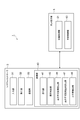
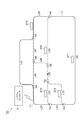
- FIG. 1 is a configuration diagram illustrating a configuration of a traveling vehicle system according to an embodiment.
- FIG. 2 is a functional block diagram showing a functional configuration of the traveling vehicle system of FIG.
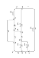
- FIG. 3 is an explanatory diagram illustrating a method for additionally setting a travel impossible section according to an embodiment.
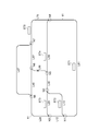
- FIG. 4 is an explanatory diagram illustrating a method for additionally setting a travel impossible section according to an embodiment.
- FIG. 5 is an explanatory diagram illustrating a method for additionally setting a travel impossible section according to an embodiment.
- FIG. 6 is a flowchart showing a method of setting the travel impossible section.
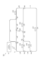
- FIG. 7 is an explanatory diagram for explaining a method for additionally setting a travel impossible section according to a modification.
- FIG. 8 is an explanatory diagram for explaining a method for additionally setting a travel impossible section according to a modification.
- the traveling vehicle system 1 is a system for transporting an object to be transported using an overhead traveling vehicle (traveling vehicle) 5 that can move along a track (traveling route).
- traveling vehicle traveling vehicle
- the traveling vehicle system 1 in which the overhead traveling vehicle 5 travels along a one-way track laid on the ceiling or the like of the factory will be described as an example.
- the traveling vehicle system 1 mainly includes a track 11, a plurality of overhead traveling vehicles 5, and a system controller 3.
- the track 11 is a part that causes the overhead traveling vehicle 5 to travel, and is suspended from the ceiling. As shown in FIG. 1, the track 11 in the traveling vehicle system 1 is sandwiched between the nodes (N1, N2, N4, N5) and the junctions (N3, N6, N7, N8), which are nodes, and the nodes. Sections (L12, L13, L23, L24, L35, L46, L47, L56, L58, L67, L78, L81).
- a station (ST1, ST2, ST3, ST4, ST5) for delivering the object to be conveyed is provided along the track 11.
- the overhead traveling vehicle 5 is configured to be able to transfer general articles that are transported objects.
- the object to be conveyed include a semiconductor wafer, a glass substrate, a general component, and the like.
- the overhead traveling vehicle 5 includes a position acquisition unit 51 and a vehicle body control unit 53 in addition to a mechanism for transferring an object to be conveyed.
- the position acquisition unit 51 is a part that acquires the position of the host vehicle on the track 11.
- the position acquisition unit 51 may include, for example, a reading unit and an encoder that read a bar code indicating point information attached to the track 11.
- the position acquisition unit 51 transmits the point information obtained by the reading unit and the travel distance after passing through the point obtained from the encoder to the system controller 3 as position data.
- the vehicle body control unit 53 is a part that controls the traveling of the overhead traveling vehicle 5, and is an electronic control unit including, for example, a CPU (Central Processing Unit), a ROM (Read Only Memory), a RAM (Random Access Memory), and the like.
- a CPU Central Processing Unit
- ROM Read Only Memory
- RAM Random Access Memory
- the system controller 3 is a part for controlling the overhead traveling vehicle 5 (traveling vehicle control step). As illustrated in FIG. 2, the system controller 3 includes an input unit 31, a display unit 32, a communication unit 33, and a control unit 40.
- the input unit 31 includes, for example, a keyboard and a mouse, and various operations and various setting values are input by the user.
- the display unit 32 includes, for example, a liquid crystal display, and displays various setting screens or an input screen to be input by the input unit 31 or the like.
- the communication unit 33 is a processing unit that communicates with other devices and the like. For example, information on stations to arrive and information for controlling the vehicle body control unit 53 are transmitted to the overhead traveling vehicle 5 via a wireless communication network. The current position of the overhead traveling vehicle 5 is received from the position acquisition unit 51. In addition, the communication unit 33 receives a transport instruction including information on a station serving as a start point and an end point from a host controller via, for example, a LAN (Local Area Network).
- LAN Local Area Network
- the control unit 40 is a part that executes various control processes (a traveling vehicle control method) in the traveling vehicle system 1 described in detail later, and includes, for example, a CPU, a ROM, a RAM, and a hard disk. As shown in FIG. 2, the control unit 40 includes a reception unit 41 as a conceptual part that executes various control processes in the traveling vehicle system 1, an abnormality determination unit 43, a travel impossible section setting unit 45, An impossible section addition setting unit 47 and a traveling vehicle control unit 49 are included. Such a conceptual part can be configured as software that is executed by the CPU after a program stored in the ROM is loaded onto the RAM, for example.
- the control unit 40 may be configured as hardware such as an electronic circuit.
- the reception unit 41 is a part that receives a non-travelable section that is a section in which entry of the overhead traveling vehicle 5 is prohibited.
- the accepting unit 41 accepts a section to be a travel impossible section via the input unit 31 in the system controller 3.
- the reception unit 41 receives an ID (identification) number of a section input to the input unit 31 by the user.
- the abnormality determination unit 43 determines whether one overhead traveling vehicle 5 that has been allowed to enter one node by the traveling vehicle control unit 49 described later does not reach one node within a predetermined time. 5 is a portion for determining that an abnormality has occurred. When the abnormality determination unit 43 determines that an abnormality has occurred in one overhead traveling vehicle 5, the abnormality determination unit 43 outputs information to that effect to the non-travelable section setting unit 45.
- the travel impossible section setting unit 45 is a section for setting a travel impossible section that is a section in which entry of the overhead traveling vehicle 5 is prohibited (untravelable section setting step).
- the travel impossible section setting unit 45 sets the travel impossible section based on the position information transmitted by the overhead traveling vehicle 5 determined by the abnormality determination unit 43. Further, the travel impossible section setting unit 45 sets a travel impossible section based on the information received by the reception unit 41.
- the travel impossible section addition setting unit 47 extracts a travel impossible section from the track 11 located upstream of the section set as the travel impossible section according to the following rules 1 and 2, and automatically adds the travel impossible section. This is a portion to be set (untravelable section additional setting step).
- rule 1 and rule 2 will be described with reference to FIGS.
- Rule 1 When the node adjacent to the upstream side of the non-running section set by the non-running section setting unit 45 is a merging section, all the sections joining the merging section are additionally set as non-running sections. To do.
- Rule 2 When the nodal point adjacent to the upstream side of the travel impossible section set by the travel impossible section setting unit 45 is a branching section, and all of the sections branched from the branching section are travel impossible sections Then, an upstream section adjacent to the branching section is additionally set as a travel impossible section.
- Rule 1 will be specifically described with reference to FIG.
- the section L67 is set as a travel impossible section by the travel impossible section setting unit 45.
- the nodal point adjacent to the upstream side of the section L67 set as the travel impossible section by the travel impossible section setting unit 45 is the junction N6.
- rule 1 is applied, and all the sections (section L46 and section L56) that join the junction N6 are additionally set as the travel-impossible sections.
- the travel impossible section addition setting unit 47 travels in accordance with the rules 1 and 2 also for the track 11 located on the upstream side of the section additionally set as the travel impossible section by the travel impossible section addition setting unit 47. It is additionally set as an impossible section.
- the section L35 is a section additionally set as a travel impossible section by the travel impossible section additional setting unit 47 as described above.
- the nodal point adjacent to the upstream side of the section L35 set as the travel impossible section by the travel impossible section setting unit 45 is the junction N3. Therefore, rule 1 is applied, and all the sections (section L13 and section L23) that join the junction N3 are additionally set as the travel-impossible sections.
- the traveling vehicle control unit 49 is a part that controls the overhead traveling vehicle 5 (traveling vehicle control step) so as not to enter the travel disabled section set by the travel disabled section setting unit 45 or the travel disabled section additional setting unit 47. Specifically, the traveling vehicle control unit 49, for example, when a travel impossible section is set in one of the sections branched from the branch section, even if there is a target station in the travel impossible section, The overhead traveling vehicle 5 is not allowed to enter the untravelable section. The traveling vehicle control unit 49 controls the overhead traveling vehicle 5 to travel in a section that is not the other travel impossible section.
- the traveling vehicle control unit 49 when the traveling vehicle control unit 49 permits one overhead traveling vehicle 5 to enter one nodal point, the traveling vehicle control unit 49 performs control so that no other overhead traveling vehicle 5 is permitted to enter the one nodal point. It is also a part to perform (blocking control). Hereinafter, the blocking control will be specifically described.
- the traveling vehicle control unit 49 associates and stores one nodal point and the ID of the overhead traveling vehicle 5 that has given permission to travel to the one nodal point (hereinafter, the ID of the overhead traveling vehicle 5 at the nodal point). Data associated with is sometimes referred to as blocking data.) Since the traveling route of the overhead traveling vehicle 5 includes a plurality of nodal points including a branching portion and a merging portion, blocking data is stored for each nodal point.
- the traveling vehicle control unit 49 When the traveling vehicle control unit 49 is requested to enter the one nodal point from the vehicle body control unit 53 in the one overhead traveling vehicle 5, the traveling vehicle control unit 49 refers to the blocking data and determines the other nodal point. It is confirmed whether permission is given to the overhead traveling vehicle 5. If there is no information on the other overhead traveling vehicle 5 associated with the one nodal point in the blocking data, the traveling vehicle control unit 49 has one nodule for the vehicle body control unit 53 in the one overhead traveling vehicle 5. Allow entry to point and update blocking information. The traveling vehicle control unit 49 deletes the blocking information for the one nodal point when the overhead traveling vehicle 5 permitted to enter the one nodal point passes the nodal point.
- the reception unit 41 receives information on a section that is desired to be set as a travel-impossible section, or the abnormality determination unit 43 determines an abnormality in the overhead traveling vehicle 5 and specifies the position of the overhead traveling vehicle 5 in which the abnormality has occurred. Thus, this setting control is started (step S1).
- the receiving unit 41 receives information that can identify a section, such as the ID of the section input from the input unit 31 by the user.
- the abnormality determination unit 43 determines that the one overhead traveling vehicle 5 that has been allowed to enter the one node by the traveling vehicle control unit 49 does not reach the one node within a predetermined time. It is determined that an abnormality has occurred in the car 5.
- the travel impossible section setting unit 45 sets the section received by the receiving unit 41 or the section specified by the abnormality determination unit 43 as a travel impossible section (step S2: travel impossible section setting step).
- the traveling vehicle control unit 49 controls the vehicle body control unit 53 so that the overhead traveling vehicle 5 does not enter the section set as the untravelable section.
- the travel impossible section additional setting unit 47 travels according to a predetermined rule (Rule 1 and Rule 2 described above) from the track 11 located upstream of the section set as the travel impossible section by the travel impossible section setting unit 45.
- a section that becomes an unusable section is extracted, and the extracted section is additionally set as a non-running section (see the upper section for rules 1 and 2).
- the travel impossible section addition setting unit 47 examines whether or not the rule 1 can be applied (step S3). Specifically, it is determined whether or not the nodal point adjacent to the upstream side of the travel impossible section set by the travel impossible section setting unit 45 is a junction.
- the travel impossible section additional setting unit 47 determines that all sections joining the joining part are included. Is additionally set as a travel impossible section (step S5).
- the travel impossible section additional setting unit 47 examines whether the rule 2 can be applied. (Step S4). Specifically, it is determined whether or not the nodal point adjacent to the upstream side of the travel impossible section set by the travel impossible section setting unit 45 is a branching section.
- the travel impossible section addition setting unit 47 when it is determined by the travel impossible section addition setting unit 47 that the node is a branching section, and all of the sections branched from the branching section are determined to be travel impossible sections (S4: YES), the travel impossible section addition setting unit 47 additionally sets the upstream section adjacent to the branch section as a travel impossible section (step S5: travel impossible section additional setting step).
- step S5 travel impossible section additional setting step
- the travel impossible section addition setting unit 47 ends the series of processes without additionally setting a new section as a travel impossible section.
- step S3 and the step S4 the additional setting of the non-running section addition setting unit 47 in the non-running section addition setting unit 47 is performed in the same manner for the section additionally set by the non-running section addition setting unit 47 in step S5.
- the non-travelable section is initially set or additionally set, if a new section is set as the non-travelable section, it is not possible to travel with respect to the newly set non-travelable section. It is determined whether there is a section to be added as a section.
- the traveling vehicle system 1 of the above-described embodiment not only the section where the abnormal overhead traveling vehicle 5 is stopped or the section arbitrarily input by the user is set as the travel-impossible section, but also the rules described above.
- a non-travelable section is automatically set.
- the traveling vehicle control unit 49 when the traveling vehicle control unit 49 permits the one overhead traveling vehicle 5 requesting permission to enter the nodal point to enter the nodal point, the other overhead traveling vehicle Blocking control that does not allow entry to the node is performed. Thereby, it can prevent that two or more overhead traveling vehicles 5 collide in a node.
- the traveling vehicle system 1 of the above-described embodiment if one overhead traveling vehicle 5 permitted to enter one node by the traveling vehicle control unit 49 does not reach one node within a predetermined time, an abnormality determination is made.
- the unit 43 determines that an abnormality has occurred in one overhead traveling vehicle 5. According to the traveling vehicle system 1 having such a configuration, it is possible to grasp the abnormality of the overhead traveling vehicle 5 with a simple configuration without newly providing a detection unit such as a sensor for grasping the abnormality of the overhead traveling vehicle 5. Can do.
- the track 11 has a first path consisting of the first section L47 that branches at the first branch portion N4 from the main path consisting of the sections L12, L24, L46, L67, L78, and L81.
- the main line path has a first junction N6 that is a junction with the second path consisting of the second section L56 on the downstream side of the first branch section N4, and the first section is on the downstream side of the first junction.
- the main path is joined.
- the traveling vehicle system 1 of this configuration even if an abnormality occurs in the one overhead traveling vehicle 5 while the one overhead traveling vehicle 5 acquires the permission of entry in the first junction N6,
- the other overhead traveling vehicles 5 can return to the main route again from the second junction N7 by bypassing the first junction N6 (via the first section L47).
- the destination is on the downstream side (for example, the station ST5) with respect to the second junction N7, it is possible to transport the transported object without changing the destination.
- ⁇ Modification 1> In the traveling vehicle system 1 of the above-described embodiment, an example in which a section that is not allowed to travel is additionally set according to the rules 1 and 2 described above has been described.
- the present invention is not limited to this.
- the abnormality determination unit 43 is permitted to enter the nodal point by the traveling vehicle control unit 49.
- the traveling vehicle system 101 configured to additionally set the section adjacent to the knot point permitted to enter as a travel impossible section when the overhead traveling vehicle 5 detects an abnormality. Good.
- FIG. 7 shows an example in which one overhead traveling vehicle 5 traveling in the section L56 becomes abnormal in the section L56 after requesting the traveling vehicle control section 49 to permit entry into the junction N6. This will be described in detail.
- the traveling vehicle control unit 49 confirms that the blocking data of the merging unit N6 is not registered, the traveling vehicle control unit 49 permits the one overhead traveling vehicle 5 to enter the merging unit N6. And the traveling vehicle control part 49 registers the blocking data of the junction part N6.
- the abnormality determination unit 43 detects an abnormality of one overhead traveling vehicle 5 that is permitted to enter the merging unit N6 by the traveling vehicle control unit 49, the non-travelable section addition setting unit 47
- the section L46 and the section 67 adjacent to the junction N6 where entry is permitted are additionally set as untravelable sections.
- the section L46 is additionally set as an untravelable section, so that another overhead traveling vehicle 5 has entered the section L46 but cannot enter the junction N6. It is possible to avoid falling into a dead-end condition.
- the subsequent overhead traveling vehicle 5 is physically Although it is possible to travel, it is possible to avoid the subsequent overhead traveling vehicle 5 from falling into a so-called bag path even when it is impossible to travel controlly as in the blocking control described above.
- the travel impossible section setting unit 45 sets the section L35 as a travel impossible section based on the position information transmitted by the overhead traveling vehicle 5 determined by the abnormality determination unit 43.
- the travel impossible section addition setting unit 47 additionally sets the sections L13 and L23 as travel impossible sections from the track 11 located on the upstream side of the section L35 according to the rule 1. Further, the travel impossible section addition setting unit 47 additionally sets the sections L58 and L56 adjacent to the branching section N5 permitted to enter, and the sections L46 and 67 adjacent to the junction N6 as travel impossible sections.
- the traveling vehicle system 101 of this embodiment not only the section 35 in which the overhead traveling vehicle 5 in which the abnormality has stopped is set as the travel-impossible section, but also the sections L13 and L23 according to the rules 1 and described above. And are automatically set as non-travelable sections.
- the section L46 is additionally set as an untravelable section, so that another overhead traveling vehicle 5 has entered the section L46 but can enter the junction N6. It is possible to avoid falling into the condition of a dead end without being lost.
- the subsequent overhead traveling vehicle 5 can physically travel, Even when it is impossible to travel in a controlled manner as in the blocking control described above, it is possible to avoid the subsequent overhead traveling vehicle 5 from falling into a so-called bag path.
- the traveling vehicle control unit 49 associates the ID of the overhead traveling vehicle 5 that has given permission to travel to both the nodal point on the entrance side of one section and the nodal point on the exit side of the section.
- the traveling vehicle control unit 49 permits the one overhead traveling vehicle 5 to enter the section L56 from the section L35, the traveling vehicle control unit 49
- the ID of the overhead traveling vehicle 5 that has given permission to travel is stored in association with the branch portion N5 on the entrance side and the junction portion N6 on the exit side of the section L56.
- the travel impossible section addition setting unit 47 cannot travel in the section adjacent to the knot point permitted to enter.
- the same effect as the traveling vehicle system 101 according to the modified example can be obtained.
- the overhead traveling vehicle 5 is described as an example of the traveling vehicle. It includes unmanned vehicles that run and stacker cranes.
Landscapes
- Engineering & Computer Science (AREA)
- Mechanical Engineering (AREA)
- Control Of Position, Course, Altitude, Or Attitude Of Moving Bodies (AREA)
Abstract
Description
ルール2:走行不可区間設定部45によって設定された走行不可区間の上流側に隣接する結節点が分岐部であり、かつ、当該分岐部から分岐する区間の全てが走行不可区間である場合には、当該分岐部に隣接する上流側の区間を走行不可区間として追加設定する。
上記実施形態の走行車システム1では、上述したルール1及びルール2に従って走行不可区間とする区間を追加設定する例を挙げて説明した。本発明は、これに限定されない。例えば、走行不可区間追加設定部47が、上述したルール1及びルール2に従って走行不可区間を追加設定する構成に加え、異常判定部43が、走行車制御部49によって結節点への進入が許可された天井走行車5の異常を検知した場合には、走行不可区間追加設定部47が、進入が許可された結節点に隣接する区間も走行不可区間として追加設定する構成の走行車システム101としてもよい。
上記実施形態及び変形例の走行車システム1,101では、走行車の一例として天井走行車5を挙げて説明したが、走行車のその他の例には、地上又は架台に配設された軌道を走行する無人走行車及びスタッカークレーンなどが含まれる。
Claims (6)
- 予め定められた一方通行の走行経路に沿って複数の走行車が走行する走行車システムであって、
前記走行経路が分岐する分岐部及び前記走行経路が合流する合流部を結節点とし、前記結節点に挟まれた前記走行経路を区間としたとき、
前記走行車の進入を禁止する前記区間である走行不可区間を設定する走行不可区間設定部と、
前記走行不可区間として設定された前記区間の上流側に位置する前記走行経路に対し、所定のルールに従って前記走行不可区間を追加設定する走行不可区間追加設定部と、
走行不可区間設定部又は走行不可区間追加設定部によって設定された前記走行不可区間に進入しないように前記走行車を制御する走行車制御部と、を備え、
前記所定のルールとは、
前記走行不可区間設定部によって設定された前記走行不可区間の上流側に隣接する前記結節点が前記合流部であった場合には、当該合流部に合流する全ての前記区間を前記走行不可区間として追加設定するというルールであり、
前記走行不可区間設定部によって設定された前記走行不可区間の上流側に隣接する前記結節点が前記分岐部であり、かつ、当該分岐部から分岐する前記区間の全てが前記走行不可区間である場合には、当該分岐部に隣接する上流側の前記区間を前記走行不可区間として追加設定するというルールである、走行車システム。 - 前記走行車は、前記結節点の手前に到達すると当該結節点への進入の許可を要求する車体制御部を有し、
前記走行車制御部は、前記結節点への進入の許可を要求する一の前記走行車に対し当該結節点への前記進入を許可すると、他の前記走行車に対し当該結節点への進入を許可しないように制御する、請求項1に記載の走行車システム。 - 前記走行車制御部によって一の前記結節点に進入を許可された一の前記走行車が所定時間内に一の前記結節点に到達しない場合には、一の前記走行車に異常が発生したと判定する異常判定部を更に備える、請求項2に記載の走行車システム。
- 前記異常判定部が、前記走行車制御部によって前記結節点への進入が許可された前記走行車の異常を検知した場合には、前記走行不可区間追加設定部は、前記進入が許可された前記結節点に隣接する前記区間を前記走行不可区間として追加設定する、請求項3に記載の走行車システム。
- 前記走行経路は、本線経路から第1分岐部において分岐する第1経路を備え、
前記本線経路は、前記第1分岐部の下流側において第2経路との合流部である第1合流部を有し、
前記第1経路は、前記第1合流部の下流側の第2合流部において本線経路に合流する、請求項2~4の何れか一項に記載の走行車システム。 - 予め定められた一方通行の走行経路に沿って複数の走行車が走行する走行車システムにおける走行車の制御方法であって、
前記走行経路が分岐する分岐部及び前記走行経路が合流する合流部を結節点とし、前記結節点に挟まれた前記走行経路を区間としたとき、
前記走行車の進入を禁止する前記区間である走行不可区間を設定する走行不可区間設定ステップと、
前記走行不可区間として設定された前記区間の上流側に位置する前記走行経路に対し、所定のルールに従って前記走行不可区間を追加設定する走行不可区間追加設定ステップと、
走行不可区間設定ステップ又は走行不可区間追加設定ステップによって設定された前記走行不可区間に進入しないように前記走行車を制御する走行車制御ステップと、を含み、
前記所定のルールとは、
前記走行不可区間設定ステップによって設定された前記走行不可区間の上流側に隣接する前記結節点が前記合流部であった場合には、当該合流部に合流する全ての前記区間を前記走行不可区間として追加設定するというルールであり、
前記走行不可区間設定ステップによって設定された前記走行不可区間の上流側に隣接する前記結節点が前記分岐部であり、かつ、当該分岐部から分岐する前記区間の全てが前記走行不可区間である場合には、当該分岐部に隣接する上流側の前記区間を前記走行不可区間として追加設定するというルールである、走行車の制御方法。
Priority Applications (2)
| Application Number | Priority Date | Filing Date | Title |
|---|---|---|---|
| US15/127,045 US9834238B2 (en) | 2014-06-02 | 2015-04-17 | Transporting vehicle system, and method of controlling transporting vehicle |
| JP2016525732A JP6176399B2 (ja) | 2014-06-02 | 2015-04-17 | 走行車システム及び走行車の制御方法 |
Applications Claiming Priority (2)
| Application Number | Priority Date | Filing Date | Title |
|---|---|---|---|
| JP2014-114090 | 2014-06-02 | ||
| JP2014114090 | 2014-06-02 |
Publications (1)
| Publication Number | Publication Date |
|---|---|
| WO2015186440A1 true WO2015186440A1 (ja) | 2015-12-10 |
Family
ID=54766520
Family Applications (1)
| Application Number | Title | Priority Date | Filing Date |
|---|---|---|---|
| PCT/JP2015/061877 Ceased WO2015186440A1 (ja) | 2014-06-02 | 2015-04-17 | 走行車システム及び走行車の制御方法 |
Country Status (4)
| Country | Link |
|---|---|
| US (1) | US9834238B2 (ja) |
| JP (1) | JP6176399B2 (ja) |
| TW (1) | TW201600444A (ja) |
| WO (1) | WO2015186440A1 (ja) |
Cited By (2)
| Publication number | Priority date | Publication date | Assignee | Title |
|---|---|---|---|---|
| WO2020230427A1 (ja) * | 2019-05-14 | 2020-11-19 | 村田機械株式会社 | 搬送システム及び搬送制御方法 |
| WO2024247603A1 (ja) * | 2023-05-31 | 2024-12-05 | 村田機械株式会社 | 走行車システム |
Families Citing this family (6)
| Publication number | Priority date | Publication date | Assignee | Title |
|---|---|---|---|---|
| SG11202008642UA (en) * | 2018-03-15 | 2020-10-29 | Murata Machinery Ltd | Traveling vehicle controller and traveling vehicle system |
| WO2019241565A1 (en) * | 2018-06-13 | 2019-12-19 | Skip Transport, Inc. | System and method for vehicle operation control |
| WO2021010013A1 (ja) * | 2019-07-17 | 2021-01-21 | 村田機械株式会社 | 走行車、走行車システム及び走行車検出方法 |
| CN111615049B (zh) * | 2020-04-17 | 2022-07-19 | 北京中交兴路车联网科技有限公司 | 基于车辆位置信息的预警方法、装置、存储介质及终端 |
| US20230384798A1 (en) * | 2020-10-26 | 2023-11-30 | Murata Machinery, Ltd. | Traveling vehicle system and method for controlling traveling vehicle |
| JP7533490B2 (ja) * | 2022-01-12 | 2024-08-14 | トヨタ自動車株式会社 | 車両搬送計画装置、管理サーバ及び車両搬送装置 |
Citations (4)
| Publication number | Priority date | Publication date | Assignee | Title |
|---|---|---|---|---|
| JPH11143538A (ja) * | 1997-11-07 | 1999-05-28 | Murata Mach Ltd | 無人搬送車システム |
| JP2009187239A (ja) * | 2008-02-06 | 2009-08-20 | Murata Mach Ltd | 移動体システム |
| JP2010176607A (ja) * | 2009-02-02 | 2010-08-12 | Toyohashi Univ Of Technology | 移動体システム及びそのデッドロック回復手法 |
| WO2013108501A1 (ja) * | 2012-01-17 | 2013-07-25 | 村田機械株式会社 | 走行車システム |
Family Cites Families (6)
| Publication number | Priority date | Publication date | Assignee | Title |
|---|---|---|---|---|
| JP3212028B2 (ja) | 1997-09-09 | 2001-09-25 | 村田機械株式会社 | 無人搬送車システム |
| WO2001002970A1 (en) * | 1999-07-02 | 2001-01-11 | Pri Automation, Inc. | Dynamic traffic based routing algorithm |
| KR101246280B1 (ko) * | 2008-09-26 | 2013-03-22 | 무라다기카이가부시끼가이샤 | 반송차 시스템 |
| US8527088B2 (en) * | 2009-03-03 | 2013-09-03 | Murata Machinery, Ltd. | Transportation system |
| JP4798554B2 (ja) * | 2009-03-05 | 2011-10-19 | 村田機械株式会社 | 走行車の走行制御システムと制御方法 |
| US20130321110A1 (en) * | 2012-06-04 | 2013-12-05 | Darryl Clines | Single-Pole Electromagnetic Transit |
-
2015
- 2015-04-17 WO PCT/JP2015/061877 patent/WO2015186440A1/ja not_active Ceased
- 2015-04-17 JP JP2016525732A patent/JP6176399B2/ja active Active
- 2015-04-17 US US15/127,045 patent/US9834238B2/en active Active
- 2015-06-01 TW TW104117667A patent/TW201600444A/zh unknown
Patent Citations (4)
| Publication number | Priority date | Publication date | Assignee | Title |
|---|---|---|---|---|
| JPH11143538A (ja) * | 1997-11-07 | 1999-05-28 | Murata Mach Ltd | 無人搬送車システム |
| JP2009187239A (ja) * | 2008-02-06 | 2009-08-20 | Murata Mach Ltd | 移動体システム |
| JP2010176607A (ja) * | 2009-02-02 | 2010-08-12 | Toyohashi Univ Of Technology | 移動体システム及びそのデッドロック回復手法 |
| WO2013108501A1 (ja) * | 2012-01-17 | 2013-07-25 | 村田機械株式会社 | 走行車システム |
Cited By (8)
| Publication number | Priority date | Publication date | Assignee | Title |
|---|---|---|---|---|
| WO2020230427A1 (ja) * | 2019-05-14 | 2020-11-19 | 村田機械株式会社 | 搬送システム及び搬送制御方法 |
| JPWO2020230427A1 (ja) * | 2019-05-14 | 2020-11-19 | ||
| CN113811498A (zh) * | 2019-05-14 | 2021-12-17 | 村田机械株式会社 | 搬送系统及搬送控制方法 |
| JP7140279B2 (ja) | 2019-05-14 | 2022-09-21 | 村田機械株式会社 | 搬送システム及び搬送制御方法 |
| TWI828906B (zh) * | 2019-05-14 | 2024-01-11 | 日商村田機械股份有限公司 | 搬送系統及搬送控制方法 |
| CN113811498B (zh) * | 2019-05-14 | 2024-02-02 | 村田机械株式会社 | 搬送系统及搬送控制方法 |
| WO2024247603A1 (ja) * | 2023-05-31 | 2024-12-05 | 村田機械株式会社 | 走行車システム |
| DE112024002363T5 (de) | 2023-05-31 | 2026-04-30 | Murata Machinery, Ltd. | Fahrzeug-fahrsystem |
Also Published As
| Publication number | Publication date |
|---|---|
| TW201600444A (zh) | 2016-01-01 |
| JPWO2015186440A1 (ja) | 2017-04-20 |
| US9834238B2 (en) | 2017-12-05 |
| JP6176399B2 (ja) | 2017-08-09 |
| US20170144681A1 (en) | 2017-05-25 |
Similar Documents
| Publication | Publication Date | Title |
|---|---|---|
| JP6176399B2 (ja) | 走行車システム及び走行車の制御方法 | |
| JP5748006B2 (ja) | 走行車システム | |
| US11226637B2 (en) | Traveling vehicle system, and control method for traveling vehicle system | |
| US10479613B2 (en) | Transport system and transport method | |
| CN112424719A (zh) | 行驶车系统 | |
| KR20200053744A (ko) | 주행 시스템, 이에 포함되는 자동 주행 장치 및 교차점 충돌 방지 방법 | |
| US20230384798A1 (en) | Traveling vehicle system and method for controlling traveling vehicle | |
| US9604657B2 (en) | Travelling vehicle system | |
| JP2004207335A (ja) | 搬送システムの制御装置 | |
| JP4172466B2 (ja) | 搬送台車システム | |
| KR102242360B1 (ko) | 반도체 반송 시스템 및 이의 반송 차량 제어 방법 | |
| KR102534375B1 (ko) | 비히클의 경로 탐색 방법 | |
| KR102842563B1 (ko) | 주행차 시스템 | |
| JP2010079554A (ja) | 搬送車システム | |
| US11217092B2 (en) | Transport vehicle system | |
| KR102459086B1 (ko) | 반송 시스템을 위한 반송차 콘트롤러 및 그 콘트롤러의 구동방법, 그리고 반송 시스템 | |
| JP2010097998A (ja) | 搬送システム | |
| CN121195216A (zh) | 行驶车系统 | |
| JP2008009638A (ja) | 走行台車システムおよび走行台車の走行制御方法 |
Legal Events
| Date | Code | Title | Description |
|---|---|---|---|
| 121 | Ep: the epo has been informed by wipo that ep was designated in this application |
Ref document number: 15802999 Country of ref document: EP Kind code of ref document: A1 |
|
| ENP | Entry into the national phase |
Ref document number: 2016525732 Country of ref document: JP Kind code of ref document: A |
|
| WWE | Wipo information: entry into national phase |
Ref document number: 15127045 Country of ref document: US |
|
| NENP | Non-entry into the national phase |
Ref country code: DE |
|
| 122 | Ep: pct application non-entry in european phase |
Ref document number: 15802999 Country of ref document: EP Kind code of ref document: A1 |