WO2015178456A1 - 電池パックおよび電池装置 - Google Patents
電池パックおよび電池装置 Download PDFInfo
- Publication number
- WO2015178456A1 WO2015178456A1 PCT/JP2015/064632 JP2015064632W WO2015178456A1 WO 2015178456 A1 WO2015178456 A1 WO 2015178456A1 JP 2015064632 W JP2015064632 W JP 2015064632W WO 2015178456 A1 WO2015178456 A1 WO 2015178456A1
- Authority
- WO
- WIPO (PCT)
- Prior art keywords
- wall
- battery
- housing
- wall portion
- casing
- Prior art date
Links
Images


Classifications
-
- H—ELECTRICITY
- H01—ELECTRIC ELEMENTS
- H01M—PROCESSES OR MEANS, e.g. BATTERIES, FOR THE DIRECT CONVERSION OF CHEMICAL ENERGY INTO ELECTRICAL ENERGY
- H01M10/00—Secondary cells; Manufacture thereof
- H01M10/60—Heating or cooling; Temperature control
- H01M10/61—Types of temperature control
- H01M10/613—Cooling or keeping cold
-
- H—ELECTRICITY
- H01—ELECTRIC ELEMENTS
- H01M—PROCESSES OR MEANS, e.g. BATTERIES, FOR THE DIRECT CONVERSION OF CHEMICAL ENERGY INTO ELECTRICAL ENERGY
- H01M10/00—Secondary cells; Manufacture thereof
- H01M10/60—Heating or cooling; Temperature control
- H01M10/62—Heating or cooling; Temperature control specially adapted for specific applications
- H01M10/625—Vehicles
-
- H—ELECTRICITY
- H01—ELECTRIC ELEMENTS
- H01M—PROCESSES OR MEANS, e.g. BATTERIES, FOR THE DIRECT CONVERSION OF CHEMICAL ENERGY INTO ELECTRICAL ENERGY
- H01M10/00—Secondary cells; Manufacture thereof
- H01M10/60—Heating or cooling; Temperature control
- H01M10/62—Heating or cooling; Temperature control specially adapted for specific applications
- H01M10/627—Stationary installations, e.g. power plant buffering or backup power supplies
-
- H—ELECTRICITY
- H01—ELECTRIC ELEMENTS
- H01M—PROCESSES OR MEANS, e.g. BATTERIES, FOR THE DIRECT CONVERSION OF CHEMICAL ENERGY INTO ELECTRICAL ENERGY
- H01M10/00—Secondary cells; Manufacture thereof
- H01M10/60—Heating or cooling; Temperature control
- H01M10/65—Means for temperature control structurally associated with the cells
- H01M10/656—Means for temperature control structurally associated with the cells characterised by the type of heat-exchange fluid
- H01M10/6561—Gases
- H01M10/6563—Gases with forced flow, e.g. by blowers
- H01M10/6565—Gases with forced flow, e.g. by blowers with recirculation or U-turn in the flow path, i.e. back and forth
-
- H—ELECTRICITY
- H01—ELECTRIC ELEMENTS
- H01M—PROCESSES OR MEANS, e.g. BATTERIES, FOR THE DIRECT CONVERSION OF CHEMICAL ENERGY INTO ELECTRICAL ENERGY
- H01M50/00—Constructional details or processes of manufacture of the non-active parts of electrochemical cells other than fuel cells, e.g. hybrid cells
- H01M50/10—Primary casings, jackets or wrappings of a single cell or a single battery
- H01M50/102—Primary casings, jackets or wrappings of a single cell or a single battery characterised by their shape or physical structure
- H01M50/103—Primary casings, jackets or wrappings of a single cell or a single battery characterised by their shape or physical structure prismatic or rectangular
-
- H—ELECTRICITY
- H01—ELECTRIC ELEMENTS
- H01M—PROCESSES OR MEANS, e.g. BATTERIES, FOR THE DIRECT CONVERSION OF CHEMICAL ENERGY INTO ELECTRICAL ENERGY
- H01M50/00—Constructional details or processes of manufacture of the non-active parts of electrochemical cells other than fuel cells, e.g. hybrid cells
- H01M50/10—Primary casings, jackets or wrappings of a single cell or a single battery
- H01M50/172—Arrangements of electric connectors penetrating the casing
- H01M50/174—Arrangements of electric connectors penetrating the casing adapted for the shape of the cells
- H01M50/176—Arrangements of electric connectors penetrating the casing adapted for the shape of the cells for prismatic or rectangular cells
-
- H—ELECTRICITY
- H01—ELECTRIC ELEMENTS
- H01M—PROCESSES OR MEANS, e.g. BATTERIES, FOR THE DIRECT CONVERSION OF CHEMICAL ENERGY INTO ELECTRICAL ENERGY
- H01M50/00—Constructional details or processes of manufacture of the non-active parts of electrochemical cells other than fuel cells, e.g. hybrid cells
- H01M50/20—Mountings; Secondary casings or frames; Racks, modules or packs; Suspension devices; Shock absorbers; Transport or carrying devices; Holders
- H01M50/204—Racks, modules or packs for multiple batteries or multiple cells
- H01M50/207—Racks, modules or packs for multiple batteries or multiple cells characterised by their shape
- H01M50/209—Racks, modules or packs for multiple batteries or multiple cells characterised by their shape adapted for prismatic or rectangular cells
-
- H—ELECTRICITY
- H01—ELECTRIC ELEMENTS
- H01M—PROCESSES OR MEANS, e.g. BATTERIES, FOR THE DIRECT CONVERSION OF CHEMICAL ENERGY INTO ELECTRICAL ENERGY
- H01M50/00—Constructional details or processes of manufacture of the non-active parts of electrochemical cells other than fuel cells, e.g. hybrid cells
- H01M50/20—Mountings; Secondary casings or frames; Racks, modules or packs; Suspension devices; Shock absorbers; Transport or carrying devices; Holders
- H01M50/218—Mountings; Secondary casings or frames; Racks, modules or packs; Suspension devices; Shock absorbers; Transport or carrying devices; Holders characterised by the material
- H01M50/22—Mountings; Secondary casings or frames; Racks, modules or packs; Suspension devices; Shock absorbers; Transport or carrying devices; Holders characterised by the material of the casings or racks
- H01M50/222—Inorganic material
- H01M50/224—Metals
-
- H—ELECTRICITY
- H01—ELECTRIC ELEMENTS
- H01M—PROCESSES OR MEANS, e.g. BATTERIES, FOR THE DIRECT CONVERSION OF CHEMICAL ENERGY INTO ELECTRICAL ENERGY
- H01M2220/00—Batteries for particular applications
- H01M2220/10—Batteries in stationary systems, e.g. emergency power source in plant
-
- H—ELECTRICITY
- H01—ELECTRIC ELEMENTS
- H01M—PROCESSES OR MEANS, e.g. BATTERIES, FOR THE DIRECT CONVERSION OF CHEMICAL ENERGY INTO ELECTRICAL ENERGY
- H01M2220/00—Batteries for particular applications
- H01M2220/20—Batteries in motive systems, e.g. vehicle, ship, plane
-
- Y—GENERAL TAGGING OF NEW TECHNOLOGICAL DEVELOPMENTS; GENERAL TAGGING OF CROSS-SECTIONAL TECHNOLOGIES SPANNING OVER SEVERAL SECTIONS OF THE IPC; TECHNICAL SUBJECTS COVERED BY FORMER USPC CROSS-REFERENCE ART COLLECTIONS [XRACs] AND DIGESTS
- Y02—TECHNOLOGIES OR APPLICATIONS FOR MITIGATION OR ADAPTATION AGAINST CLIMATE CHANGE
- Y02E—REDUCTION OF GREENHOUSE GAS [GHG] EMISSIONS, RELATED TO ENERGY GENERATION, TRANSMISSION OR DISTRIBUTION
- Y02E60/00—Enabling technologies; Technologies with a potential or indirect contribution to GHG emissions mitigation
- Y02E60/10—Energy storage using batteries
Definitions
- Embodiments described herein relate generally to a battery pack and a battery device.
- a battery pack including a casing and a plurality of battery modules provided on a lower wall portion (outer wall portion) of the casing and having a space for flowing air inside each of the casing is known.
- the battery pack according to the embodiment includes, for example, a first housing and a plurality of battery modules.
- the first housing has a first outer wall portion and a second outer wall portion spaced from the first outer wall portion.
- the plurality of battery modules are provided in the first casing, and each has a second casing and a plurality of battery cells accommodated in the second casing. At least one of the plurality of battery modules is connected to the first outer wall, and the second casing of the plurality of battery modules is connected to the second outer wall.
- a second housing of at least one battery module different from that connected to the one outer wall portion is connected.
- FIG. 1 is an exploded perspective view of an example of the battery pack according to the first embodiment.
- FIG. 2 is a side view of a first housing member as an example of the battery pack according to the first embodiment.
- FIG. 3 is a perspective view of a state in which the battery module as an example of the battery pack according to the first embodiment is attached to the housing, as viewed from the side opposite to the outer wall portion (side of the housing).
- FIG. 4 is an exploded perspective view of FIG.
- FIG. 5 is an exploded perspective view of a battery module as an example of the battery pack according to the first embodiment.
- FIG. 6 is a perspective view of a battery cell as an example of the battery pack according to the first embodiment.
- FIG. 7 is a perspective view of the battery module as an example of the battery pack according to the first embodiment as viewed from the outer wall side.
- FIG. 8 is a perspective view of a state in which the battery module as an example of the battery pack of the first embodiment is attached to the housing as seen through from the outer wall side.
- FIG. 9 is a side view of the first housing member as an example of the battery pack according to the second embodiment.
- FIG. 10 is a side view of the first housing member as an example of the battery pack according to the third embodiment.
- FIG. 11 is a side view showing a schematic configuration of an example of the battery pack of the fourth embodiment.
- FIG. 12 is a side view showing a schematic configuration of an example of the battery pack of the fifth embodiment.
- FIG. 13 is a side view showing a schematic configuration of an example of the battery pack of the sixth embodiment.
- FIG. 14 is a side view showing a schematic configuration of an example of the battery pack of the seventh embodiment.
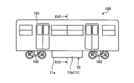
- FIG. 15 is a side view of an example of a vehicle including the battery device according to the eighth embodiment.
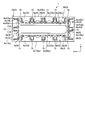
- 16 is a cross-sectional view taken along the line XVI-XVI in FIG.
- FIG. 17 is a plan view of an example of the battery device according to the eighth embodiment.
- the battery pack 1 (battery system, assembled battery device, storage battery device) includes a housing 2 (first housing) and a plurality of (for example, 10) housings in the housing 2. Two battery modules 3 (assembled batteries).
- the battery pack 1 is installed in various devices, machines, facilities, and the like, and is used as a power source for these various devices, machines, and facilities.
- the battery pack 1 is used as a mobile power source such as an LRT (Light Rail Transit) train or automobile power source, or a stationary type power source such as a POS (Point Of Sales) system power source. Also used as a power source.
- LRT Light Rail Transit
- POS Point Of Sales
- the housing 2 is configured in a rectangular parallelepiped shape.
- the housing 2 has a plurality of wall portions 2a to 2c.
- any one of the plurality of wall portions 2a to 2c can be used in a posture along a plane.
- the direction is defined based on the posture of the wall 2c along the plane.
- the X direction is the longitudinal direction of the housing 2 (short direction of the housing 6 and the thickness direction of the battery cell 7), and the Y direction is the short direction of the housing 2 (longitudinal direction of the housing 6 and the battery cell 7).
- the Z direction are the height direction of the housing 2 (the height direction of the housing 6 and the height direction of the battery cell 7).
- the X direction, the Y direction, and the Z direction are orthogonal to each other.
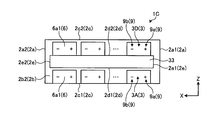
- the wall portion 2a includes a wall portion 2a1 and a wall portion 2a2 that are provided in parallel to each other with an interval in the longitudinal direction (X direction) of the housing 2.
- Each of the wall 2a1 and the wall 2a2 extends (expands) along a direction (in this embodiment, for example, a direction orthogonal to the YZ plane) that intersects the longitudinal direction (X direction) of the housing 2.
- the wall portion 2b includes a wall portion 2b1 and a wall portion 2b2 provided in parallel to each other with an interval in the short direction (Y direction) of the housing 2.
- Each of the wall 2b1 and the wall 2b2 extends (expands) in a direction (in this embodiment, for example, an orthogonal direction, an XZ plane) that intersects the short direction (Y direction) of the housing 2.
- the wall 2a and the wall 2b can be referred to as a side wall or the like.
- the wall portion 2c includes a wall portion 2c1 and a wall portion 2c2 that are provided in parallel with each other at an interval in the height direction (Z direction) of the housing 2.
- Each of the wall 2c1 and the wall 2c2 extends (expands) in a direction (in this embodiment, for example, an orthogonal direction, an XY plane) that intersects the height direction (Z direction) of the housing 2.
- the wall 2c1 may be referred to as a lower wall (bottom wall) or the like, and the wall 2c2 may be referred to as an upper wall (top wall) or the like.
- Each of the plurality of wall portions 2a to 2c has an outer surface 2g and an inner surface 2h. Further, the plurality of wall portions 2a to 2c constitute an outer shell of the housing 2, that is, an outer wall portion.
- the housing 2 can be configured by combining a plurality of parts (divided bodies).
- the housing 2 includes a first housing member 2A (case) including at least wall portions 2a and 2c, and a second housing member 2B (first housing) including at least the wall portion 2b1.
- An opening 2e penetrating in the short direction (Y direction) of the housing 2 is provided inside the first housing member 2A.
- the second housing member 2B is positioned on one side in the Y direction of the first housing member 2A (front side in FIG. 1), and closes the opening 2e from the one side.
- the third housing member 2C is located on the other side (the back side in FIG. 1) in the Y direction of the first housing member 2A, and closes the opening 2e from the other side.
- the first housing member 2A, the second housing member 2B, and the third housing member 2C can be made of, for example, a metal material.
- the seal member 4 is provided between the first housing member 2A and the second housing member 2B and between the first housing member 2A and the third housing member 2C. , 5 (for example, gaskets and packings).
- the seal members 4 and 5 are configured in, for example, a rectangular frame shape along the edge (end, side) of the wall 2b (opening 2e).
- the second housing member 2B is coupled (integrated) with the first housing member 2A via the seal member 4
- the third housing member 2C is coupled with the first housing member 2A via the seal member 5. (Integrated). That is, the peripheral edge of the housing 2 is liquid-tightly closed by the seal members 4 and 5.
- the first housing member 2A, the second housing member 2B, the third housing member 2C, and the like can be provided with vent holes or the like if dust, iron powder, water droplets, or the like can be prevented from entering the housing 2.
- a dust filter and a trip that cover the vent hole may be provided.
- the plurality of battery modules 3 are housed in the housing 2 having at least dustproof and dripproof properties.
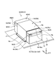
- the battery module 3 (assembled battery) includes a housing 6 (second housing) and a plurality (e.g., eighteen) battery cells 7 (single unit) accommodated in the housing 6. Battery) and conductive members 8 and 9 that electrically connect the plurality of battery cells 7.
- a plurality of (for example, six) battery cells 7 arranged in a line along the short direction (X direction) of the housing 6 are disposed along the longitudinal direction (Y direction) of the housing 6. It is accommodated in the housing 6 in a state in which groups (for example, three groups) are arranged.
- Each of the plurality of battery cells 7 has a pair of positive electrode terminal 13 and negative electrode terminal 14.
- the positive electrode terminal 13 and the negative electrode terminal 14 are coupled to the conductive members 8 and 9 while penetrating through an opening 6 f provided in the housing 6.
- the positive terminal 13 and the negative terminal 14 of two battery cells 7 adjacent in the longitudinal direction (Y direction) and the short direction (X direction) of the housing 6 are electrically connected via the conductive member 8.
- the conductive member 8 Are connected to each other, and electric power is taken out via a conductive member 9 (output terminal portion) provided at an end of the housing 6.
- the housing 6 (second housing) has a rectangular parallelepiped shape.
- the housing 6 has a plurality of wall portions 6a to 6c.
- the wall portion 6a includes a wall portion 6a1 and a wall portion 6a2 that are provided in parallel to each other at an interval in the longitudinal direction (Y direction) of the housing 6.
- Each of the wall portion 6a1 and the wall portion 6a2 extends (expands) in a direction intersecting with the longitudinal direction (Y direction) of the housing 6 (in this embodiment, for example, a direction orthogonal to the XZ plane).
- the wall portion 6b includes a wall portion 6b1 and a wall portion 6b2 that are provided in parallel with each other at an interval in the short direction (X direction) of the housing 6.
- Each of the wall 6b1 and the wall 6b2 extends (expands) in a direction (in this embodiment, for example, an orthogonal direction, a YZ plane) that intersects the short direction (X direction) of the housing 6.
- the wall 6a and the wall 6b may be referred to as a side wall or the like.
- the wall portion 6c includes a wall portion 6c1 and a wall portion 6c2 that are provided in parallel with each other at an interval in the height direction (Z direction) of the housing 6.
- Each of the wall 6c1 and the wall 6c2 extends (expands) in a direction (in this embodiment, for example, an orthogonal direction, an XY plane) that intersects the height direction (Z direction) of the housing 6.
- the wall 6c1 may be referred to as a lower wall (bottom wall) or the like, and the wall 6c2 may be referred to as an upper wall (top wall) or the like.
- Each of the plurality of wall portions 6a to 6c has an outer surface 6g and an inner surface 6h.
- the housing 6 includes a plurality of (for example, two) wall portions 6i parallel to the wall portion 6a and a plurality of (for example, five) wall portions parallel to the wall portion 6b. 6j.
- Each of the wall portions 6i is located between the wall portion 6a1 and the wall portion 6a2 and extends between the wall portion 6b1 and the wall portion 6b2.
- the wall portion 6i is provided with a space in the longitudinal direction (Y direction) of the housing 6 together with the wall portion 6a1 and the wall portion 6a2, and a plurality of (for example, three) accommodation regions (for example, three) in the Y direction are provided inside the housing 6. It is divided (compartmental) into accommodation spaces.
- all the wall parts 6j are located between wall part 6b1 and wall part 6b2, and span between wall part 6a1 and wall part 6a2.
- the wall portion 6j is provided with an interval in the short direction (X direction) of the housing 6 together with the wall portion 6b1 and the wall portion 6b2, and the housing 6 has a plurality of (for example, six) accommodation regions in the X direction. It is divided into (accommodating spaces). That is, in the present embodiment, a total of eighteen accommodating chambers 6e are provided in the housing 6 by the wall portions 6a and 6i and the wall portions 6b and 6j that intersect each other. One battery cell 7 is placed in each storage chamber 6e.
- the battery cells 7 and the wall portions 6i are alternately stacked in the Y direction, and the battery cells 7 and the wall portions 6j are alternately stacked in the X direction.
- the wall 6i and the wall 6j can be referred to as a partition wall, a partition wall, a separation wall, or the like.
- the wall portions 6i and 6j are an example of an insulating portion.
- the housing 6 can be configured by combining a plurality of parts (divided bodies).
- the housing 6 includes a first housing member 6A (lower case, first case) and a second housing member 6B (middle case, second case). And a third housing member 6C (upper case, third case, cover, lid member).
- the first housing member 6A includes at least a wall 6c1 and a part of the walls 6a and 6b.
- the second housing member 6B includes at least a part of the wall portions 6a and 6b.
- the third housing member 6C includes at least a wall 6c2 and part of the walls 6a and 6b.
- the wall portions 6i and 6j are included in at least one of the first housing member 6A, the second housing member 6B, and the third housing member 6C (for example, the first housing member 6A).
- the first housing member 6A, the second housing member 6B, and the third housing member 6C are made of a material having a lower thermal conductivity than the housing 2 (for example, a synthetic resin material having an insulating property). sell.
- the plurality of battery modules 3 are insulated from each other.
- the battery cell 7 can be configured as, for example, a lithium ion secondary battery.
- the battery cell 7 may be another secondary battery such as a nickel metal hydride battery, a nickel cadmium battery, or a lead storage battery.
- a lithium ion secondary battery is a kind of non-aqueous electrolyte secondary battery, and lithium ions in the electrolyte are responsible for electrical conduction.
- the positive electrode material include lithium manganese composite oxide, lithium nickel composite oxide, lithium cobalt composite oxide, lithium nickel cobalt composite oxide, lithium manganese cobalt composite oxide, spinel type lithium manganese nickel composite oxide, and olivine.
- an oxide-based material such as lithium titanate (LTO), or niobium represented by the general formula LixM (1-y) NbyNb2O (7 + ⁇ ) is used.
- An oxide material such as a complex oxide is used.
- M is, for example, at least one selected from the group consisting of Ti and Zr, and x, y, and ⁇ are 0 ⁇ x ⁇ 6, 0 ⁇ y ⁇ 1, and ⁇ 1 ⁇ ⁇ ⁇ 1, respectively. It is a numerical value satisfying.
- electrolyte for example, electrolyte solution
- An organic solvent or the like may be used alone or in combination.
- the battery cell 7 (unit cell) has a housing 11 (container), a positive electrode terminal 13, and a negative electrode terminal 14.
- the housing 11 is comprised by the flat rectangular parallelepiped shape thin in the X direction.
- the housing 11 can be made of, for example, a metal material or a synthetic resin material.
- an electrode body, an electrolytic solution, and the like are accommodated.
- the electrode body includes, for example, a positive electrode sheet, a negative electrode sheet, and an insulating layer (separator).
- the electrode body may be formed in a flat shape by winding (folding) a positive electrode sheet, a negative electrode sheet, and an insulating layer.
- the electrode body is an electrode group and functions as a power generation element.
- the positive terminal 13 and the negative terminal 14 are provided on the surface 11 a (upper surface, top surface) of the housing 11. Specifically, the positive electrode terminal 13 is located on one end side in the Y direction of the surface 11a, and the negative electrode terminal 14 is located on the other end side in the Y direction of the surface 11a.
- the positive electrode terminal 13 is provided so as to penetrate the surface 11 a of the housing 11, and is connected to the positive electrode lead of the electrode body inside the housing 11.
- the negative electrode terminal 14 is provided in a state of penetrating the surface 11 a of the housing 11, and is connected to the negative electrode lead of the electrode body inside the housing 11.
- the positive electrode terminal 13 and the negative electrode terminal 14 can each be made of a conductive material.
- the plurality of battery cells 7 are in a posture in which each surface 11 a faces the same direction (upward in FIG. 5), and the longitudinal direction (Y direction) and the short direction ( In the X direction). Further, the plurality of battery cells 7 are arranged so that the positive terminals 13 and the negative terminals 14 are alternately arranged in the direction along the longitudinal direction (Y direction) of the casing 6, for example. In the direction along the hand direction (X direction), the positive terminals 13 and the negative terminals 14 are arranged alternately.
- an adhesive is poured between the battery cell 7 and the inner surface 6h of the storage chamber 6e in a state where the battery cell 7 is placed in each of the storage chamber 6e.
- the plurality of battery cells 7 are fixed (that is, bonded) to the wall portions 6a and 6b (side wall portions), the wall portions 6i and 6j (partition wall portions), and the like by an adhesive that is solidified later.
- an adhesive may be applied in advance to the inner surface 6h of the wall portion 6c1 (bottom wall portion) and the surface 11b (lower surface, bottom surface) of the housing 11 before the battery cell 7 is placed in the accommodation chamber 6e. .
- the wall 6c1 (housing 6) and the surface 11b (battery cell 7) are in contact with each other and connected.
- the wall 6c1 (housing 6) and the surface 11b (battery cell 7) are indirectly connected via the adhesive.
- the adhesive has thermal conductivity. Therefore, in this embodiment, the wall 6c1 of the housing 6 is thermally connected to all the battery cells 7 accommodated in the housing 6.
- the conductive members 8 and 9 are configured as thin plate bus bars, for example.
- the conductive members 8 and 9 are coupled (fixed or connected) to the positive terminal 13 and the negative terminal 14 exposed from the opening 6f of the second housing member 6B, for example, by welding or the like.
- One of the pair of conductive members 9 functions as a positive electrode terminal 9a, and the other functions as a negative electrode terminal 9b.
- the positive electrode terminal 9a is connected to the positive electrode terminal 13 of any one battery cell 7, and the negative electrode terminal 9b is connected to the negative electrode terminal 14 of a battery cell 7 different from the battery cell 7 to which the positive electrode terminal 9a is connected. . Also, as shown in FIGS.
- the positive terminal 9a and the negative terminal 9b are inserted into (not accommodated in) the notch 6d (recess, groove) of the third housing member 6C in a state of protruding from the wall 6a1.
- the positive electrode terminal 9 a and the negative electrode terminal 9 b function as output terminal portions of the battery module 3.
- substrate 10 is provided in the 2nd housing member 6B.
- the board 10 is electrically connected to, for example, the conductive members 8 and 9 and a temperature sensor (not shown) and functions as a monitoring board for monitoring the voltage and temperature of the battery and a control board for battery control. be able to.
- substrate 10 is located in the approximate center part of the Y direction of the 2nd housing member 6B.
- the conductive members 8 and 9, the temperature sensor, and the like are located outside the substrate 10 in the Y direction.
- substrate 10 was provided in the 2nd housing member 6B (battery module 3), it does not need to be provided. In this case, the function of the substrate 10 may be divided and incorporated in the battery cell 7.
- the plurality of battery modules 3 includes a first battery module 3A, a second battery module 3B, and a third battery module 3C.
- the first battery module 3A is attached to the wall 2c1 (lower wall) of the housing 2 and is thermally connected to the wall 2c1.
- the second battery module 3B is a battery module different from the first battery module 3A among the plurality of battery modules 3, and is attached to the wall 2c2 (upper wall) of the housing 2, and the wall 2c2 Thermally connected.
- the third battery module 3 ⁇ / b> C is a battery module different from the first battery module 3 ⁇ / b> A and the second battery module 3 ⁇ / b> B among the plurality of battery modules 3, and the wall 2 a (side wall) of the housing 2. And is thermally connected to the wall 2a.
- four first battery modules 3A are arranged side by side along the X direction (first direction) on the wall 2c1
- the four second battery modules 3B are arranged on the wall 2c2.
- two third battery modules 3C are arranged along the Z direction on the wall 2a1, and the remaining two third battery modules 3C are connected to the wall.
- the first battery module 3A, the second battery module 2B, and the third battery module 3C are arranged circumferentially as a whole.
- all the battery modules 3 are attached to wall part 2a1, 2a2, 2c1, 2c2 as an outer wall part (peripheral wall part).
- the wall 2c1 is an example of a first outer wall
- the wall 2c2 is an example of a second outer wall.
- the plurality of battery modules 3 are attached to the wall portions 2a1, 2a2, 2c1, and 2c2 such that the respective wall portions 6a1 face the same direction (front side in the Y direction in FIG. 1).
- the wall 6a1 is a wall provided with the positive terminal 9a and the negative terminal 9b. As shown in FIGS. 4 and 5, the positive terminal 9 a and the negative terminal 9 b are formed on the wall 6 c 2 (upper wall) rather than the wall 6 c 1 (lower wall) where the plurality of battery cells 7 are thermally connected. Located nearby.
- the wall portion 6c1 is an example of a first wall portion
- the wall portion 6c2 is an example of a second wall portion.
- wall part 6c1 (lower wall part) of the some battery module 3 has faced wall part 2a1, 2a2, 2c1, 2c2 side to which each is attached. That is, the wall 6c1 and the wall 2c1 of the first battery module 3A face each other, and the wall 6c1 and the wall 2c2 of the second battery module 3B face each other. Further, the wall 6c1 and the wall 2a1 of the third battery module 3C on one side in the X direction (right side in FIG. 2) face each other, and the third battery module on the other side in the X direction (left side in FIG. 2). The 3C wall 6c1 and the wall 2a2 face each other.
- the first battery module 3A and the second battery module 3B are provided in a state (posture) that is inverted with respect to each other in the height direction (Z direction) of the housing 2, and are provided on one side and the other side in the X direction.
- the third battery module 3 ⁇ / b> C is provided in a state (attitude) that is mutually inverted in the longitudinal direction (X direction) of the housing 2. Therefore, in the first battery module 3A, each positive electrode terminal 9a is positioned on one side (right side in FIG. 2) in the X direction (first direction), and in the second battery module 3B, each positive electrode terminal 9a. Is located on the other side in the X direction (left side in FIG. 2).
- each positive electrode terminal 9a is positioned on one side in the Z direction (upper side in FIG. 2) and the other side in the X direction (see FIG. 2).
- each positive electrode terminal 9 a is positioned on the other side in the Z direction (lower side in FIG. 2).
- the negative terminals 9b of the first battery module 3A, the second battery module 3B, and the third battery module 3C are located on the side opposite to the respective positive terminals 9a.
- the positive terminal 9 a and the negative terminal 9 b of two battery modules 3 adjacent to each other in the longitudinal direction (X direction) and the height direction (Z direction) of the housing 2 are electrically connected via the conductive member 15.
- the conductive member 15 Are connected to each other, and electric power is taken out through a pair of conductive members 19 provided at the end of the housing 2.
- One of the pair of conductive members 19 is connected to the positive terminal 9a of any one of the battery modules 3, and the other is connected to the negative terminal 9b of a battery module 3 different from the battery module 3 to which one is connected.
- the plurality of battery modules 3 are arranged in a circumferential shape as a whole, and the positive terminals 9a and the negative terminals 9b are alternately arranged along the circumferential direction. Therefore, according to the present embodiment, for example, the plurality of battery modules 3 can be connected (electrically connected) in a circumferential shape via the conductive member 15. Therefore, a series circuit of a plurality of battery modules 3 having an arbitrary pair of two battery modules 3 adjacent to each other as one end and the other end can be configured. Therefore, for example, the degree of freedom in layout of the pair of conductive members 19 (for example, output cables) is likely to increase.
- the pair of conductive members 19 for example, output cables
- the positive electrode terminal 9a and the negative electrode terminal 9b of each battery module 3 are located in the wall part 6c2 side (center part side of the housing
- the plurality of battery modules 3, that is, the first battery module 3 ⁇ / b> A, the second battery module 3 ⁇ / b> B, and the third battery module 3 ⁇ / b> C are provided with a bracket 16 and a coupler 17 (for example, a screw). And the bolts are connected (fixed) to the wall portions 2a1, 2a2, 2c1, 2c2 to which they are attached.
- the bracket 16 includes a substantially U-shaped base portion 16a that overlaps the pair of wall portions 6b1 and 6b2 and the wall portion 6c2 of the housing 6, a projecting portion 16b that protrudes in a flange shape from the outer edge portion of the base portion 16a and overlaps the inner surface 2h, Have The protrusion 16b is provided with an opening 16c (see FIG. 4) through which the coupler 17 is passed.
- the height of the bracket 16 (the height in the Z direction) is substantially the same as the height of the housing 6 (the height in the Z direction).
- a thin plate-like elastic member 18 is interposed between the base portion 16a and the wall portion 6c2.
- the elastic member 18 can be made of, for example, rubber, elastomer, synthetic resin material, silicon resin material, or the like.
- the coupler 17 passed through the opening 16c of the bracket 16 is coupled (fixed) to the wall portions 2a1, 2a2, 2c1, 2c2 to which the coupling member 17 is attached in a state where the elastic member 18 is elastically contracted.
- the bracket 16 and the coupler 17 are an example of a coupling portion that couples the housing 2 and the housing 6.
- bond part may be comprised with a coupling band, an adhesive agent, a double-sided tape etc., for example.
- casing 2 is filled may be sufficient.
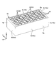
- a first portion 20 is provided on the wall portion 6 c 1 (bottom wall portion) of the housing 6.
- the first portion 20 includes a plurality of first members 21 (wall portions, ribs) extending along the longitudinal direction (Y direction) of the housing 6 and the short direction (X direction) of the housing 6.
- a plurality of second members 22 (wall portions, ribs) extending.
- the first members 21 are provided in parallel with each other in the short direction (X direction) of the housing 6, and the second members 22 are spaced in the longitudinal direction (Y direction) of the housing 6.
- the first portion 20 is configured in a lattice shape by connecting the first member 21 and the second member 22 while crossing each other.
- the first portion 20 is provided with a quadrangular recess 23 (groove) surrounded by two first members 21 and two second members 22. .
- the recess 23 is recessed from the outer surface 6g of the wall 6c1 toward the inner surface 6h. According to the present embodiment, the rigidity and strength of the housing 6 are easily increased by the lattice-shaped first portion 20 provided on the wall 6c1.
- the heat conductive member 25 can be made of, for example, a synthetic resin material containing a heat conductive filler (metal material).
- a plurality of heat conducting members 25 divided into thin plates are placed (accommodated) in the recesses 23 of the wall 6c1.
- the thickness (the thickness in the Z direction) of the heat conducting member 25 is set to be slightly larger than the depth of the recess 23 (the depth in the Z direction).
- the plurality of battery modules 3 are coupled (fixed) to the respective wall portions 2a1, 2a2, 2c1, and 2c2 in a state where the heat conducting member 25 is elastically contracted.
- the heat conducting member 25 is an example of a heat conducting layer.
- the heat conductive layer may be, for example, a heat conductive sheet, grease, an adhesive, or the like.
- the heat conducting member 25 may have a thin plate-like base and a plurality of protrusions protruding from the base, and the plurality of protrusions may be inserted into the recesses 23.
- the housing 6 and the wall portion 2c1 of the first battery module 3A are thermally connected, and the housing 6 and the wall portion 2c2 of the second battery module 3B are thermally connected.
- the housing 6 of the third battery module 3C on one side in the X direction (right side in FIG. 2) and the wall 2a1 are thermally connected, and the third on the other side in the X direction (left side in FIG. 2). Of the battery module 3C is thermally connected to the wall portion 2a2.
- the housing 6 and the housing 2 of the battery module 3 may be thermally connected without the heat conducting member 25 interposed.
- the wall 6 c 1 and the heat conducting member 25 are attached to the walls 2 a 1, 2 a 2, 2 c 1, 2 c 2 by the elastic force of the elastic member 18. Pressed against. Therefore, according to this embodiment, the heat of the battery cell 7 accommodated in the housing 6 can be effectively transferred to the wall portions 2a1, 2a2, 2c1, and 2c2 through the wall portion 6c1 and the heat conducting member 25. .
- the plurality of battery modules 3 includes at least one (four in the present embodiment) first battery connected to the wall 2c1 (first outer wall).
- the module 3A includes at least one (four in the present embodiment) second battery module 3B connected to the wall 2c2 (second outer wall). Therefore, according to this embodiment, for example, the heat of the battery cells 7 of the first battery module 3A and the second battery module 3B is transferred to the walls 2c1 and 2c2 by heat transfer via the respective housings 6. I can escape. Therefore, for example, more battery modules 3 are easily cooled with a simpler configuration.
- the wall 2c1 (first outer wall) and the wall 2c2 (second outer wall) face each other. Therefore, according to the present embodiment, for example, the two wall portions 2c1 and 2c2 facing each other are disposed on the wall portions 2c1 and 2c2 for releasing heat from the plurality of battery modules 3 positioned between the wall portions 2c1 and 2c2.
- a plurality (four in the present embodiment) of first battery modules 3A are arranged along the X direction (first direction), and each of the first battery modules 3A is arranged.
- the positive terminal 9a is positioned on one side in the X direction
- each negative terminal 9b is positioned on the other side in the X direction. Therefore, according to the present embodiment, for example, the plurality of first battery modules 3A arranged along the X direction are relatively easily connected via the conductive member 15, and are connected in series by the plurality of first battery modules 3A. Circuits are relatively easy to obtain.
- a plurality (four in this embodiment) of the second battery modules 3B are arranged along the X direction (first direction), and each of the second battery modules 3B is arranged.
- the positive terminal 9a is positioned on the other side in the X direction
- each negative terminal 9b is positioned on one side in the X direction. That is, the arrangement of the positive terminal 9a and the negative terminal 9b of the first battery module 3A is reversed. Therefore, according to the present embodiment, for example, a series circuit including a plurality of first battery modules 3A and a plurality of second battery modules 3B can be obtained relatively easily.
- the housing 6 of the first battery module 3A and the second battery module 3B includes a wall 6c1 (first wall) connected to the walls 2c1 and 2c2, and a wall.
- Wall 6c2 (second wall) opposite to the portion 6c1, and the positive terminal 9a and the negative terminal 9b are positioned closer to the wall 6c2 than the wall 6c1 of the housing 6. . Therefore, according to the present embodiment, for example, the positive terminal 9a and the negative terminal 9b of the first battery module 3A and the second battery module 3B are positioned on the center side (inner peripheral side) of the housing 2. Cheap.
- the total length of the plurality of conductive members 15 is larger. , Tend to be shorter.
- the housing 6 of the first battery module 3A and the second battery module 3B includes a wall 6c1 (first wall) connected to the walls 2c1 and 2c2, and a wall.
- a wall 6c2 (second wall) opposite to the portion 6c1, and a plurality of battery cells 7 are connected to the wall 6c1. Therefore, according to this embodiment, the heat of the some battery cell 7 can be escaped to wall part 2c1, 2c2 by the heat transfer via wall part 6c1. Therefore, for example, the first battery module 3A and the second battery module 3B (battery cell 7 thereof) are compared with a configuration in which a wall portion different from the wall portion 6c1 of the housing 6 is connected to the wall portions 2c1 and 2c2. ) Is easier to cool more effectively.
- the plurality of battery modules 3 are accommodated in at least a housing 2 (first housing) having dust resistance and drip resistance. Therefore, according to this embodiment, for example, intrusion of dust, iron powder, water droplets, or the like into the inside of the housing 2 is easily suppressed. Therefore, for example, by ensuring the dustproof and dripproof properties of the housing 2, the influence of the dust and water on the battery module 3 is suppressed, and the heat dissipation of the battery module 3 is likely to increase.
- the elastic member 18 that presses the housings 6 of the first battery module 3A and the second battery module 3B against the wall portions 2c1 and 2c2 is provided. Therefore, according to the present embodiment, the wall 6c1 and the walls 2c1 and 2c2 of the housing 6 are more likely to be in close contact with each other by the elastic force of the elastic member 18. Therefore, for example, the heat of the battery cell 7 is likely to be effectively transmitted to the wall portions 2 c 1 and 2 c 2 via the wall portion 6 c 1 of the housing 6.
- the housing 2 is made of a material (metal material) having a higher thermal conductivity than the housing 6 of the plurality of battery modules 3. Therefore, according to the present embodiment, for example, the heat of the plurality of battery cells 7 accommodated in the housing 6 is likely to be effectively transmitted to the housing 2 by heat transfer via the housing 6.
- the entire housing 2 is made of a metal material, but at least a part of the housing 2 (for example, a portion to which the wall portion 6c1 is attached) may be made of a metal material.
- the battery module 3 is attached and thermally connected to the four wall portions 2a1, 2a2, 2c1, and 2c2 as the outer wall portions, but the wall portion 2b1 and the wall portion as the outer wall portions are further connected.
- the battery module 3 may be attached to 2b2 and thermally connected.
- convection (circulation) fluid gas, liquid, etc.
- the heat generated in the battery module 3 can be transported by convection.
- the battery pack 1A according to the embodiment shown in FIG. 9 has the same configuration as the battery pack 1 of the first embodiment. Therefore, also according to this embodiment, the same result (effect) based on the same configuration as that of the first embodiment can be obtained.
- the cooling mechanism 30 is provided in 2c1 and 2c2.
- the cooling mechanism 30 includes, for example, a heat sink (heat radiation part) 30a.
- a plate-shaped heat sink 30a is thermally connected to the outer surfaces 2g of the wall portions 2a1, 2a2, 2c1, and 2c2.
- the heat of the battery cell 7 is transmitted from the wall portion 6c1 of the housing 6 to the heat sink 30a via the wall portions 2a1, 2a2, 2c1, and 2c2, and is released from the heat sink 30a.
- the cooling mechanism 30 may further include a fan or the like that cools the heat sink 30a.
- the cooling mechanism 30 may be comprised by the water cooling unit (oil cooling unit) etc. which circulate coolant along wall part 2a1, 2a2, 2c1, 2c2.
- the cooling mechanism 30 (heat sink 30a) is provided in each of the four wall portions 2a1, 2a2, 2c1, and 2c2, but the cooling mechanism is provided in any one of the wall portions (for example, the wall portion 2c2). 30 may be provided.
- the cooling mechanism 30 can be obtained by one cooling mechanism 30. Can be cooled.
- the battery pack 1B according to the embodiment shown in FIG. 10 has the same configuration as the battery pack 1 of the first embodiment. Therefore, also according to this embodiment, the same result (effect) based on the same configuration as that of the first embodiment can be obtained.
- the housing 2 is provided with an opening 33.
- the opening 33 can be configured as, for example, a through-hole penetrating the housing 2 along the short direction (Y direction, see FIG. 1).
- At least one of the wall 2b1 and the wall 2b2 has a rectangular tube shape extending over the edge of the opening 33 of the wall 2b1 and the edge of the opening 33 of the wall 2b2.
- Wall portions 2d and 2e are provided.
- the wall portion 2d includes wall portions 2d1 and 2d2 extending in parallel along the X direction at intervals in the Z direction.
- the wall portion 2e includes wall portions 2e1 and 2e2 that extend in parallel along the Z direction with an interval in the X direction.
- the opening 33 is configured (formed) by the six wall portions 2b1, 2b2, 2d1, 2d2, 2e1, and 2e2.
- elastic members 40 are interposed between the wall 2d1 and the wall 6c2 of the first battery module 3A, and between the wall 2d2 and the wall 6c2 of the second battery module 3B, respectively.
- the elastic member 40 can be configured by a spring or the like, for example.
- the housings 6 of the first battery module 3A and the second battery module 3B are fixed to the walls 2c1 and 2c2 while being pressed against the walls 2c1 and 2c2 by the elastic member 40. ing. Therefore, according to the present embodiment, the elastic member 40 can also serve as a coupling portion that couples the housing 2 and the housing 6. Therefore, for example, the number of parts of the battery pack 1B is likely to be reduced.
- the wall 6c1 and the walls 2c1 and 2c2 of the housing 6 are more likely to be in close contact with each other, and the heat of the battery cell 7 is transmitted through the wall 6c1 of the housing 6 It is easy to be transmitted effectively by 2c1 and 2c2.
- a battery pack 1C according to the embodiment shown in FIG. 11 has the same configuration as the battery pack 1 of the first embodiment. Therefore, also according to this embodiment, the same result (effect) based on the same configuration as that of the first embodiment can be obtained.
- the plurality of battery modules 3 include a first battery module 3A and a fourth battery module 3D.
- the first battery module 3A is attached to the wall 2c1 (lower wall) of the housing 2.
- the fourth battery module 3D is a battery module different from the first battery module 3A among the plurality of battery modules 3, and is attached to the wall 2d2 of the housing 2.
- the wall portion 2d2 is a wall portion separated from the wall portion 2c1, and constitutes (forms) a part of the opening portion 33 as in the third embodiment.
- the wall 2d2 is a wall on the opposite side of the wall 2d1 facing the wall 2c1. That is, the wall 2c1 and the wall 2d2 do not face each other.
- the wall 2c1 is an example of a first outer wall
- the wall 2d2 is an example of a second outer wall.
- the first battery module 3A and the fourth battery module 3D are disposed in the same posture on the respective wall portions 2c1 and 2d2. That is, in the first battery module 3A and the fourth battery module 3D, each positive electrode terminal 9a is positioned on one side (right side in FIG. 11) in the X direction (first direction), and each negative electrode terminal 9b is It is located on the other side in the X direction (left side in FIG. 11).
- the first battery module 3A and the fourth battery module 3D can be coupled (fixed) to the walls 2c1 and 2d2 by, for example, the bracket 16 and the coupler 17 (see FIG. 2).
- the heat of the battery cells 7 of the first battery module 3A and the fourth battery module 3D is transferred to the walls 2c1 and 2d2 by heat transfer via the respective housings 6. I can escape.
- the opening 33 is configured as a through-hole penetrating the housing 2, but the opening 33 is formed of a wall portion of the housing 2 (for example, wall portions 2 b 1 and 2 b 2 (side wall portions), It may be a recess provided in FIG.
- the battery pack 1D according to the embodiment shown in FIG. 12 has the same configuration as the battery pack 1 of the first embodiment. Therefore, also according to this embodiment, the same result (effect) based on the same configuration as that of the first embodiment can be obtained.
- the plurality of battery modules 3 are thermally connected to the first battery module 3A thermally connected to the wall 2c1 and to the wall 2c2.
- Second battery module 3B and a fourth battery module 3D thermally connected to the walls 2d1 and 2d2.
- the plurality of first battery modules 3A and the plurality of fourth battery modules 3D on the wall 2d1 side are provided in a state (attitude) reversed from each other in the height direction (Z direction).
- the plurality of second battery modules 3B and the plurality of fourth battery modules 3D on the wall 2d2 side are provided in a state (attitude) reversed from each other in the height direction (Z direction).
- the wall 2c1 is an example of a first outer wall
- the walls 2c2, 2d1, and 2d2 are examples of a second outer wall.
- a battery pack 1E according to the embodiment shown in FIG. 13 has the same configuration as the battery pack 1 of the first embodiment. Therefore, also according to this embodiment, the same result (effect) based on the same configuration as that of the first embodiment can be obtained.
- the plurality of battery modules 3 are thermally connected to the first battery module 3 ⁇ / b> A that is thermally connected to the wall portion 2 c 1 and to the wall portion 2 c 2.
- all the battery modules 3 are attached to the six wall portions 2a1, 2a2, 2c1, 2c2, 2d1, and 2d2 as the outer wall portions.
- the battery pack 1F according to the embodiment shown in FIG. 14 has the same configuration as the battery pack 1 of the first embodiment. Therefore, also according to this embodiment, the same result (effect) based on the same configuration as that of the first embodiment can be obtained.
- the fan device 50 is provided in the housing 2 of the battery pack 1F.
- the fan device 50 is an example of a first flow device.
- the plurality of battery modules 3 are housed in a casing 2 that is dust-proof and drip-proof and is substantially sealed.
- the fan device 50 circulates (flows) the gas (fluid) in the substantially sealed housing 2.
- the heat in the housing 2 is easily transferred to the wall portions 2a1, 2a2, 2c1, 2c2 and the wall portions 2b1, 2b2 (see FIG. 1) as outer wall portions, and the heat dissipation of the battery module 3 is improved. it can.
- FIG. 1 the wall portions 2a1, 2a2, 2c1, 2c2 and the wall portions 2b1, 2b2
- the fan device 50 is provided facing the space between the first battery module 3A and the second battery module 3B that are separated from each other. An air flow that flows along the surface of the wall 6c2 of the housing 6 is generated. As described above, the heat of the battery cells 7 of the first battery module 3A and the second battery module 3B is transferred from the wall 6c1 side of each housing 6 to the housing 2, so that the wall 6c1 side There is a possibility that the wall 6c2 side (the positive electrode terminal 9a and the negative electrode terminal 9b side, the center part side of the housing 2) becomes higher in temperature. In this respect, according to the present embodiment, the heat of the wall 6c2 side (center side of the housing 2) can be efficiently transported by the air flow of the fan device 50.
- the battery module 3 depending on the location There is an advantage that variation in the cooling effect (temperature) is easily suppressed. Therefore, for example, the life of the battery module 3 and thus the battery pack 1F may be easily extended.
- the wall 2a1, 2a2, 2b1, 2b2, 2c1, 2c2, etc. of the housing 2 may be provided with the cooling mechanism 30 (see FIG. 9) of the second embodiment.
- the cooling mechanism 30 can cool the plurality of battery modules 3 more effectively.
- the case where the fan device 50 that allows the gas in the housing 2 to flow is provided is exemplified, but the present invention is not limited to this.
- the housing 2 contacts the plurality of battery modules 3. While the liquid (fluid) to be put is put in, the flow apparatus which flows the liquid in the housing
- the battery device 70 (battery system, storage battery device) includes, for example, a housing 71 (housing, case) and a plurality of (for example, three) housings 71.
- a battery pack 1F and a fan device 60 are provided.
- the battery device 70 is installed in various devices, machines, facilities, etc., and can be used as a power source for these various devices, machines, facilities.
- the case where the battery apparatus 70 is mounted under the floor of the rail vehicle 100 is illustrated as an example, However, The battery apparatus 70 of this embodiment is not limited to this.
- the battery device 70 may be mounted on the roof of the railway vehicle 100, or may be mounted on a vehicle other than the railway vehicle 100 such as a bus (automobile).
- the battery device 70 includes the battery pack 1F of the seventh embodiment, but includes the battery packs 1, 1A to 1E of the first to sixth embodiments instead of the battery pack 1F. Also good.
- the three battery packs 1F are provided in the housing 71 of the battery device 70, but one, two, or four or more battery packs 1F may be provided.
- the container 71 has a plurality of wall portions 71a to 71c.
- the wall portion 71a is configured in a vertically long rectangular shape in the front-rear direction (traveling direction) of the railway vehicle 100 in plan view.
- the wall portion 71a is referred to as a lower wall, a bottom wall, or the like, and faces (opposites and overlaps) the wall portion 2b (2b2) of the battery pack 1F, for example.
- the wall portion 71b is provided at both ends of the wall portion 71a in the lateral direction, and protrudes from the wall portion 71a to one side in the thickness direction of the wall portion 71a (upper side in FIG. 16).
- the short direction of the wall portion 71a is along the vehicle width direction of the railcar 100
- the longitudinal direction of the wall portion 71a is along the front-rear direction of the railcar 100
- the thickness direction of the wall portion 71a is Along the vertical direction of the railway vehicle 100.
- the wall portion 71b is referred to as a side wall, a standing wall, or the like, and faces (opposites and overlaps) the wall portion 2c (2c1, 2c2) of the battery pack 1F, for example.
- the container 71 is opened toward the one side in the thickness direction of the wall 71a (upper side in FIG. 16) by the wall 71a and the two walls 71b connected to each other.
- a recessed portion 71d is formed.
- the plurality of battery packs 1 ⁇ / b> F are accommodated in the recesses 71 d in a state in which the respective longitudinal directions are along the longitudinal direction of the railway vehicle 100 and are spaced from each other in the vehicle width direction of the railway vehicle 100. Has been (placed).
- the plurality of battery packs 1F can be coupled (fixed) to the housing 71 by a coupling portion such as an adhesive, the bracket 16, and the coupling tool 17 (see FIG. 3).
- the wall portion 71c is provided at an end portion on one side in the height direction of the wall portion 71b (upper side in FIG. 16), and protrudes from the wall portion 71b toward the outer side in the short direction of the wall portion 71a.
- the wall portion 71c is referred to as an overhang portion, a flange, or the like, and faces the mounting portion 101a provided on the vehicle body 101 of the railway vehicle 100 (opposites and overlaps).
- the wall 71 c is provided with a plurality of openings 71 r spaced from each other in the front-rear direction of the railway vehicle 100.
- the container 71 is coupled (fixed) to the vehicle body 101 by engaging a nut with a bolt passed through the opening 71r of the wall 71c and the opening (not shown) of the mounting portion 101a. sell.
- the fan device 60 is provided in the housing 71.
- the fan device 60 generates, for example, an air flow that is sucked from one end of the recess 71d in the longitudinal direction (the longitudinal direction of the railway vehicle 100) and discharged from the other end.
- the fan device 60 is an example of a second flow device.
- the air sucked into the container 71 by the fan device 60 passes through a gap (passage) between two battery packs 1F adjacent to each other and flows out downstream of the battery pack 1F. That is, the fan device 60 generates an air flow along the surfaces of the wall portions 2c1 and 2c2 facing each other of the two battery packs 1F.
- the wall parts 2c1 and 2c2 to which the plurality of battery modules 3 are thermally connected can be cooled by the air flow, the heat dissipation of the battery pack 1F can be improved.
- a heat conducting member 58 is provided between the two wall portions 71 b of the container 71 and the two battery packs 1 ⁇ / b> F on both sides in the vehicle width direction of the railway vehicle 100. It has been. Therefore, a part of the heat generated in the two battery packs 1F is released to the outside of the container 71 through the heat conducting member 58 and the wall portion 71b.
- the heat conductive member 58 can be made of, for example, a synthetic resin material containing a heat conductive filler (metal material). As shown in FIG. 17, in the present embodiment, more heat is more easily released into the gap (passage) between two adjacent battery packs 1F than between the wall portion 71b and the battery pack 1F. Become.
- the heat conducting member 58 is an example of a heat conducting layer.
- the heat conductive layer may be, for example, a heat conductive sheet, grease, an adhesive, or the like.
- the heat conducting member 58 is provided between the wall 71b and the battery pack 1F.
- one fan device 60 is provided in the container 71, but a plurality of fan devices 60 may be provided for each gap (passage) between the two battery packs 1F.
- a filter device 55 is provided on the upstream side of the fan device 60 of the container 71.
- the filter device 55 can be configured as, for example, a two-layer type filter that is a combination of an inertia filter and a hepa filter.
- the filter device 55 may be composed of a combination of other filters, or may be composed of a multilayer type of two or more layers, or a single layer type. Therefore, according to the present embodiment, for example, the filter device 55 can suppress the intrusion of dust or moisture into the container 71.
- the container 71 has a plurality of wall portions 71t.
- the wall portion 71t is referred to as a partition wall portion, a partition wall, a separation wall, or the like, and extends between the filter device 55 and the fan device 60.
- the wall portion 71t defines a space portion on the upstream side and a space portion on the downstream side of the fan device 60 of the container 71. Thereby, for example, it is possible to prevent the airflow that has flowed out downstream of the fan device 60 from returning to the upstream space of the fan device 60 and being sucked into the fan device 60 again.
- the battery device 70 is installed in the space between the two wheels 102 in the front-rear direction of the railway vehicle 100.
- Various devices other than the battery device 70 can be arranged under the floor of the railway vehicle 100.
- the battery device 70 since the battery device 70 includes the fan device 60, for example, even when traveling wind is blocked by other devices, the fan device 60 can more reliably cool the plurality of battery packs 1 ⁇ / b> F. Can do.
- the case where both sides in the longitudinal direction of the container 71 (the longitudinal direction of the railway vehicle 100) are opened is illustrated, but the container 71 is substantially sealed as in the seventh embodiment. It may be.
- the heat dissipation of the battery pack 1 ⁇ / b> F can be enhanced by circulating the gas in the container 71 by the fan device 60.
- a fluid (fluid) that comes into contact with the plurality of battery packs 1 ⁇ / b> F may be placed in the substantially sealed container 71, and a fluid device that causes the liquid in the container 71 to flow may be provided.
- the air flow is discharged from the end portion on the other side in the longitudinal direction of the container 71. For example, the end portion on the other side is blocked by the wall portion, and the air is supplied to the wall portion 71a.
- a flow outlet hole may be provided.
- the railway vehicle 100 may reciprocate along the route, when the discharge hole is opened along the front-rear direction (traveling direction) of the railway vehicle 100, a difference occurs in the air flow discharge capacity between the forward path and the backward path. There is a risk that. In that respect, by providing the discharge hole in the wall portion 71a, it is possible to suppress a difference in the air flow discharge capability between the forward path and the return path.
Abstract
Description
図1,2に示されるように、電池パック1(電池システム、組電池装置、蓄電池装置)は、筐体2(第一の筐体)と、筐体2に収容される複数(例えば、十二個)の電池モジュール3(組電池)と、を備える。電池パック1は、種々の装置や、機械、設備等に設置され、それら種々の装置や、機械、設備の電源として使用される。例えば、電池パック1は、LRT(Light Rail Transit)等の電車や自動車の電源等、移動型の電源としても使用される他、例えば、POS(Point Of Sales)システム用の電源等、定置型の電源としても使用される。また、種々の装置等には、本実施形態に示される複数の電池パック1を、直列あるいは並列に接続したセットとして搭載することもできる。
図9に示される実施形態にかかる電池パック1Aは、上記第1実施形態の電池パック1と同様の構成を備えている。よって、本実施形態によっても、上記第1実施形態と同様の構成に基づく同様の結果(効果)が得られる。
図10に示される実施形態にかかる電池パック1Bは、上記第1実施形態の電池パック1と同様の構成を備えている。よって、本実施形態によっても、上記第1実施形態と同様の構成に基づく同様の結果(効果)が得られる。
図11に示される実施形態にかかる電池パック1Cは、上記第1実施形態の電池パック1と同様の構成を備えている。よって、本実施形態によっても、上記第1実施形態と同様の構成に基づく同様の結果(効果)が得られる。
図12に示される実施形態にかかる電池パック1Dは、上記第1実施形態の電池パック1と同様の構成を備えている。よって、本実施形態によっても、上記第1実施形態と同様の構成に基づく同様の結果(効果)が得られる。
図13に示される実施形態にかかる電池パック1Eは、上記第1実施形態の電池パック1と同様の構成を備えている。よって、本実施形態によっても、上記第1実施形態と同様の構成に基づく同様の結果(効果)が得られる。
図14に示される実施形態にかかる電池パック1Fは、上記第1実施形態の電池パック1と同様の構成を備えている。よって、本実施形態によっても、上記第1実施形態と同様の構成に基づく同様の結果(効果)が得られる。
図15~17に示されるように、電池装置70(電池システム、蓄電池装置)は、例えば、収容体71(筐体、ケース)と、収容体71に収容される複数(例えば、三個)の電池パック1Fと、ファン装置60と、を備える。電池装置70は、種々の装置や、機械、設備等に設置され、それら種々の装置や、機械、設備の電源として使用されうる。なお、本実施形態では、一例として、電池装置70が鉄道車両100の床下に搭載された場合が例示されるが、本実施形態の電池装置70は、これに限定されない。電池装置70は、例えば、鉄道車両100の屋根に搭載されてもよいし、バス(自動車)等の鉄道車両100以外の車両に搭載されてもよい。また、本実施形態では、電池装置70が上記第7実施形態の電池パック1Fを備えているが、電池パック1Fに換えて上記第1~6実施形態の電池パック1,1A~1Eを備えてもよい。さらに、本実施形態では、電池装置70の収容体71に三個の電池パック1Fが設けられているが、一個、二個、あるいは四個以上の電池パック1Fが設けられてもよい。
Claims (12)
- 第一の外壁部と、前記第一の外壁部と離間した第二の外壁部と、を有した第一の筐体と、
前記第一の筐体内に設けられ、それぞれが第二の筐体、および前記第二の筐体に収容された複数の電池セルを有した、複数の電池モジュールと、
を備え、
前記第一の外壁部には、前記複数の電池モジュールのうちの少なくとも一つの、前記第二の筐体が、接続され、
前記第二の外壁部には、前記複数の電池モジュールのうち前記第二の筐体が前記第一の外壁部に接続されたものとは別の少なくとも一つの前記電池モジュールの、前記第二の筐体が、接続された、電池パック。 - 前記第一の外壁部と第二の外壁部とは互いに向き合った、請求項1に記載の電池パック。
- 前記複数の電池モジュールは、それぞれ正極端子および負極端子を有し、
前記第一の外壁部に前記第二の筐体が接続された複数の前記電池モジュールが第一の方向に沿って並び、
前記第一の外壁部に沿って並んだ前記複数の電池モジュールの前記正極端子は、前記第一の方向の一方側に位置されるとともに、前記負極端子は他方側に位置された、請求項1または2に記載の電池パック。 - 前記第二の外壁部に前記第二の筐体が接続された複数の前記電池モジュールが前記第一の方向に沿って並び、
前記第二の外壁部に沿って並んだ前記複数の電池モジュールの前記正極端子は、前記第一の方向の他方側に位置されるとともに、前記負極端子は一方側に位置された、請求項3に記載の電池パック。 - 前記第一の外壁部または前記第二の外壁部に前記第二の筐体が接続された前記電池モジュールの当該第二の筐体は、前記第一の外壁部または前記第二の外壁部と接続された第一の壁部と、当該第一の壁部とは反対側の第二の壁部とを有し、
前記正極端子および前記負極端子は、前記第二の筐体の前記第一の壁部よりも前記第二の壁部の近くに位置された、請求項3または4に記載の電池パック。 - 前記第一の外壁部または前記第二の外壁部に前記第二の筐体が接続された前記電池モジュールの当該第二の筐体は、前記第一の外壁部または前記第二の外壁部と接続された第一の壁部と、当該第一の壁部とは反対側の第二の壁部とを有し、
前記複数の電池セルが前記第一の壁部と接続された、請求項1~5のうちいずれか1項に記載の電池パック。 - 前記第一の筐体には開口部が設けられ、
前記第一の外壁部および前記第二の外壁部のうち少なくとも一方が、前記開口部の一部を形成している、請求項1~6のうちいずれか1項に記載の電池パック。 - 前記第一の筐体は、少なくとも、防塵性および防滴性を有した、請求項1~7のうちいずれか1項に記載の電池パック。
- 前記第一の外壁部および前記第二の外壁部のうち少なくとも一方を冷却する冷却機構を備えた、請求項1~8のうちいずれか1項に記載の電池パック。
- 前記第二の筐体を前記第一の外壁部または前記第二の外壁部に押し付ける弾性部材を備えた、請求項1~9のうちいずれか1項に記載の電池パック。
- 前記第一の筐体内の流体を流動させる第一の流動装置を備えた、請求項1~10のうちいずれか1項に記載の電池パック。
- 複数の、請求項1~11のうちいずれか1項に記載の電池パックと、
前記複数の電池パックを収容する収容体と、
前記収容体内の流体を流動させる第二の流動装置と、
を備えた、電池装置。
Priority Applications (3)
| Application Number | Priority Date | Filing Date | Title |
|---|---|---|---|
| EP15796632.6A EP3147964B1 (en) | 2014-05-22 | 2015-05-21 | Battery pack and battery device |
| JP2016521148A JP6282731B2 (ja) | 2014-05-22 | 2015-05-21 | 電池パックおよび電池装置 |
| US15/354,414 US20170069888A1 (en) | 2014-05-22 | 2016-11-17 | Battery pack and battery device |
Applications Claiming Priority (2)
| Application Number | Priority Date | Filing Date | Title |
|---|---|---|---|
| JP2014106542 | 2014-05-22 | ||
| JP2014-106542 | 2014-05-22 |
Related Child Applications (1)
| Application Number | Title | Priority Date | Filing Date |
|---|---|---|---|
| US15/354,414 Continuation US20170069888A1 (en) | 2014-05-22 | 2016-11-17 | Battery pack and battery device |
Publications (1)
| Publication Number | Publication Date |
|---|---|
| WO2015178456A1 true WO2015178456A1 (ja) | 2015-11-26 |
Family
ID=54554117
Family Applications (1)
| Application Number | Title | Priority Date | Filing Date |
|---|---|---|---|
| PCT/JP2015/064632 WO2015178456A1 (ja) | 2014-05-22 | 2015-05-21 | 電池パックおよび電池装置 |
Country Status (4)
| Country | Link |
|---|---|
| US (1) | US20170069888A1 (ja) |
| EP (1) | EP3147964B1 (ja) |
| JP (1) | JP6282731B2 (ja) |
| WO (1) | WO2015178456A1 (ja) |
Cited By (3)
| Publication number | Priority date | Publication date | Assignee | Title |
|---|---|---|---|---|
| WO2019004069A1 (ja) * | 2017-06-30 | 2019-01-03 | 日立オートモティブシステムズ株式会社 | 電池パック |
| JP2020191156A (ja) * | 2019-05-17 | 2020-11-26 | 株式会社東芝 | 電池モジュール、電池パック及び車両 |
| US11509013B2 (en) * | 2016-03-23 | 2022-11-22 | Mitsubishi Electric Corporation | Storage battery module |
Families Citing this family (9)
| Publication number | Priority date | Publication date | Assignee | Title |
|---|---|---|---|---|
| JP6308188B2 (ja) * | 2015-09-07 | 2018-04-11 | 株式会社デンソー | 電池パック |
| GB2568242A (en) * | 2017-11-06 | 2019-05-15 | Moog Unna Gmbh | Secure Battery Housing Tray |
| CN108091799A (zh) * | 2017-12-07 | 2018-05-29 | 珠海格力精密模具有限公司 | 电池模组及包括其的动力电池 |
| CN108123080B (zh) * | 2017-12-19 | 2021-11-19 | 义乌市旻具五金工具有限公司 | 一种用于日常应急的多功能锂电池箱 |
| DE102018214722A1 (de) * | 2018-08-30 | 2020-03-05 | Robert Bosch Gmbh | Batteriesystem und Verfahren zur homogenen Temperaturverteilung innerhalb des Batteriesystems |
| DE102018214749A1 (de) * | 2018-08-30 | 2020-03-05 | Robert Bosch Gmbh | Batteriesystem mit mindestens einem Lüfter |
| US11121408B2 (en) * | 2019-03-14 | 2021-09-14 | Medtronic, Inc. | Lithium-ion battery |
| US11811088B2 (en) * | 2019-09-19 | 2023-11-07 | Kabushiki Kaisha Toshiba | Separator, electrode group, secondary battery, battery pack, vehicle, and stationary power supply |
| JP7416005B2 (ja) * | 2021-03-31 | 2024-01-17 | トヨタ自動車株式会社 | 蓄電装置 |
Citations (5)
| Publication number | Priority date | Publication date | Assignee | Title |
|---|---|---|---|---|
| JPS5814672U (ja) * | 1981-07-22 | 1983-01-29 | 株式会社ユアサコーポレーション | 集合蓄電池装置 |
| JP2003257390A (ja) * | 2002-02-27 | 2003-09-12 | Japan Storage Battery Co Ltd | 組電池 |
| JP2010003520A (ja) * | 2008-06-19 | 2010-01-07 | Hitachi Ltd | 電池箱およびこれを備える鉄道車両 |
| US20120115003A1 (en) * | 2010-11-05 | 2012-05-10 | Shi-Dong Park | Battery module |
| JP2013546124A (ja) * | 2010-10-19 | 2013-12-26 | コミサリア ア レネルジ アトミク エ オウ エネルジ アルタナティヴ | 自動車の電気モータのための電池 |
Family Cites Families (8)
| Publication number | Priority date | Publication date | Assignee | Title |
|---|---|---|---|---|
| JP5330810B2 (ja) * | 2008-11-18 | 2013-10-30 | 株式会社日立製作所 | 電池モジュールを収容する電池箱及びそれを備える鉄道車両 |
| KR100937897B1 (ko) * | 2008-12-12 | 2010-01-21 | 주식회사 엘지화학 | 신규한 공냉식 구조의 중대형 전지팩 |
| KR101173870B1 (ko) * | 2010-08-18 | 2012-08-14 | 에스비리모티브 주식회사 | 전지 모듈 |
| JPWO2012133708A1 (ja) * | 2011-03-31 | 2014-07-28 | 三洋電機株式会社 | 電源装置及び電源装置を備える車両 |
| JP6107114B2 (ja) * | 2012-01-16 | 2017-04-05 | 株式会社Gsユアサ | 電源装置 |
| KR101371739B1 (ko) * | 2012-09-07 | 2014-03-12 | 기아자동차(주) | 배터리 시스템 |
| JP5664690B2 (ja) * | 2013-03-29 | 2015-02-04 | 株式会社豊田自動織機 | 電池パック |
| KR101814735B1 (ko) * | 2013-05-29 | 2018-01-03 | 삼성에스디아이 주식회사 | 배터리 모듈 |
-
2015
- 2015-05-21 EP EP15796632.6A patent/EP3147964B1/en active Active
- 2015-05-21 WO PCT/JP2015/064632 patent/WO2015178456A1/ja active Application Filing
- 2015-05-21 JP JP2016521148A patent/JP6282731B2/ja active Active
-
2016
- 2016-11-17 US US15/354,414 patent/US20170069888A1/en not_active Abandoned
Patent Citations (5)
| Publication number | Priority date | Publication date | Assignee | Title |
|---|---|---|---|---|
| JPS5814672U (ja) * | 1981-07-22 | 1983-01-29 | 株式会社ユアサコーポレーション | 集合蓄電池装置 |
| JP2003257390A (ja) * | 2002-02-27 | 2003-09-12 | Japan Storage Battery Co Ltd | 組電池 |
| JP2010003520A (ja) * | 2008-06-19 | 2010-01-07 | Hitachi Ltd | 電池箱およびこれを備える鉄道車両 |
| JP2013546124A (ja) * | 2010-10-19 | 2013-12-26 | コミサリア ア レネルジ アトミク エ オウ エネルジ アルタナティヴ | 自動車の電気モータのための電池 |
| US20120115003A1 (en) * | 2010-11-05 | 2012-05-10 | Shi-Dong Park | Battery module |
Non-Patent Citations (1)
| Title |
|---|
| See also references of EP3147964A4 * |
Cited By (8)
| Publication number | Priority date | Publication date | Assignee | Title |
|---|---|---|---|---|
| US11509013B2 (en) * | 2016-03-23 | 2022-11-22 | Mitsubishi Electric Corporation | Storage battery module |
| WO2019004069A1 (ja) * | 2017-06-30 | 2019-01-03 | 日立オートモティブシステムズ株式会社 | 電池パック |
| JP2019012619A (ja) * | 2017-06-30 | 2019-01-24 | 日立オートモティブシステムズ株式会社 | 電池パック |
| JP7099807B2 (ja) | 2017-06-30 | 2022-07-12 | ビークルエナジージャパン株式会社 | 電池パック |
| JP2022115909A (ja) * | 2017-06-30 | 2022-08-09 | ビークルエナジージャパン株式会社 | 電池パック |
| JP2020191156A (ja) * | 2019-05-17 | 2020-11-26 | 株式会社東芝 | 電池モジュール、電池パック及び車両 |
| CN113273022A (zh) * | 2019-05-17 | 2021-08-17 | 株式会社东芝 | 电池模组、电池组及车辆 |
| JP7199303B2 (ja) | 2019-05-17 | 2023-01-05 | 株式会社東芝 | 電池モジュール、電池パック及び車両 |
Also Published As
| Publication number | Publication date |
|---|---|
| JPWO2015178456A1 (ja) | 2017-07-13 |
| EP3147964A4 (en) | 2018-02-28 |
| EP3147964B1 (en) | 2020-05-20 |
| JP6282731B2 (ja) | 2018-02-21 |
| EP3147964A1 (en) | 2017-03-29 |
| US20170069888A1 (en) | 2017-03-09 |
Similar Documents
| Publication | Publication Date | Title |
|---|---|---|
| JP6282731B2 (ja) | 電池パックおよび電池装置 | |
| JP6505236B2 (ja) | バッテリーパック | |
| US9859533B2 (en) | Energy storage apparatus | |
| JP6922683B2 (ja) | 電池パック、電池パックの製造方法及び介在部材 | |
| JP6385766B2 (ja) | 車両用蓄電池装置 | |
| JP6658387B2 (ja) | 電池パック | |
| US20200203784A1 (en) | Battery module and battery pack | |
| CN109690812B (zh) | 蓄电池装置以及车辆 | |
| CN109309182B (zh) | 封闭元件、封闭模块、存储模块和用于提供电能的布置及运输车辆 | |
| JP2011175743A (ja) | 電源装置及びこれを備える車両 | |
| US9460862B2 (en) | Electric storage cell, electric storage apparatus, and vehicle having electric storage apparatus | |
| JP6694297B2 (ja) | 電池モジュール | |
| JP2020021752A (ja) | 電池装置 | |
| JP6926712B2 (ja) | 蓄電装置 | |
| JP2018116816A (ja) | 電池モジュール | |
| JP6845116B2 (ja) | 電池モジュールおよび電池装置 | |
| JP2018032520A (ja) | 蓄電装置 | |
| JP7475480B2 (ja) | 電池モジュールおよびこれを含む電池パック | |
| JP2019009022A (ja) | 電池装置 | |
| JP6773417B2 (ja) | 電池モジュール | |
| JP2018032591A (ja) | 電池パック | |
| WO2021166626A1 (ja) | 蓄電装置 | |
| JP7078757B2 (ja) | 電池パック | |
| WO2021166554A1 (ja) | 蓄電装置 | |
| JP6999238B2 (ja) | 電池モジュール及び組電池 |
Legal Events
| Date | Code | Title | Description |
|---|---|---|---|
| 121 | Ep: the epo has been informed by wipo that ep was designated in this application |
Ref document number: 15796632 Country of ref document: EP Kind code of ref document: A1 |
|
| ENP | Entry into the national phase |
Ref document number: 2016521148 Country of ref document: JP Kind code of ref document: A |
|
| NENP | Non-entry into the national phase |
Ref country code: DE |
|
| REEP | Request for entry into the european phase |
Ref document number: 2015796632 Country of ref document: EP |
|
| WWE | Wipo information: entry into national phase |
Ref document number: 2015796632 Country of ref document: EP |