WO2015178453A1 - 円筒状断熱材及びその製造方法 - Google Patents
円筒状断熱材及びその製造方法 Download PDFInfo
- Publication number
- WO2015178453A1 WO2015178453A1 PCT/JP2015/064608 JP2015064608W WO2015178453A1 WO 2015178453 A1 WO2015178453 A1 WO 2015178453A1 JP 2015064608 W JP2015064608 W JP 2015064608W WO 2015178453 A1 WO2015178453 A1 WO 2015178453A1
- Authority
- WO
- WIPO (PCT)
- Prior art keywords
- fired
- carbon fiber
- screen
- wound body
- fiber felt
- Prior art date
- Legal status (The legal status is an assumption and is not a legal conclusion. Google has not performed a legal analysis and makes no representation as to the accuracy of the status listed.)
- Ceased
Links
Images


Classifications
-
- B—PERFORMING OPERATIONS; TRANSPORTING
- B32—LAYERED PRODUCTS
- B32B—LAYERED PRODUCTS, i.e. PRODUCTS BUILT-UP OF STRATA OF FLAT OR NON-FLAT, e.g. CELLULAR OR HONEYCOMB, FORM
- B32B1/00—Layered products having a non-planar shape
- B32B1/08—Tubular products
-
- B—PERFORMING OPERATIONS; TRANSPORTING
- B29—WORKING OF PLASTICS; WORKING OF SUBSTANCES IN A PLASTIC STATE IN GENERAL
- B29C—SHAPING OR JOINING OF PLASTICS; SHAPING OF MATERIAL IN A PLASTIC STATE, NOT OTHERWISE PROVIDED FOR; AFTER-TREATMENT OF THE SHAPED PRODUCTS, e.g. REPAIRING
- B29C53/00—Shaping by bending, folding, twisting, straightening or flattening; Apparatus therefor
- B29C53/56—Winding and joining, e.g. winding spirally
- B29C53/562—Winding and joining, e.g. winding spirally spirally
-
- B—PERFORMING OPERATIONS; TRANSPORTING
- B29—WORKING OF PLASTICS; WORKING OF SUBSTANCES IN A PLASTIC STATE IN GENERAL
- B29C—SHAPING OR JOINING OF PLASTICS; SHAPING OF MATERIAL IN A PLASTIC STATE, NOT OTHERWISE PROVIDED FOR; AFTER-TREATMENT OF THE SHAPED PRODUCTS, e.g. REPAIRING
- B29C53/00—Shaping by bending, folding, twisting, straightening or flattening; Apparatus therefor
- B29C53/80—Component parts, details or accessories; Auxiliary operations
- B29C53/8008—Component parts, details or accessories; Auxiliary operations specially adapted for winding and joining
- B29C53/8083—Improving bonding of wound materials or layers
-
- B—PERFORMING OPERATIONS; TRANSPORTING
- B29—WORKING OF PLASTICS; WORKING OF SUBSTANCES IN A PLASTIC STATE IN GENERAL
- B29C—SHAPING OR JOINING OF PLASTICS; SHAPING OF MATERIAL IN A PLASTIC STATE, NOT OTHERWISE PROVIDED FOR; AFTER-TREATMENT OF THE SHAPED PRODUCTS, e.g. REPAIRING
- B29C53/00—Shaping by bending, folding, twisting, straightening or flattening; Apparatus therefor
- B29C53/80—Component parts, details or accessories; Auxiliary operations
- B29C53/84—Heating or cooling
-
- B—PERFORMING OPERATIONS; TRANSPORTING
- B29—WORKING OF PLASTICS; WORKING OF SUBSTANCES IN A PLASTIC STATE IN GENERAL
- B29C—SHAPING OR JOINING OF PLASTICS; SHAPING OF MATERIAL IN A PLASTIC STATE, NOT OTHERWISE PROVIDED FOR; AFTER-TREATMENT OF THE SHAPED PRODUCTS, e.g. REPAIRING
- B29C70/00—Shaping composites, i.e. plastics material comprising reinforcements, fillers or preformed parts, e.g. inserts
- B29C70/04—Shaping composites, i.e. plastics material comprising reinforcements, fillers or preformed parts, e.g. inserts comprising reinforcements only, e.g. self-reinforcing plastics
- B29C70/28—Shaping operations therefor
- B29C70/30—Shaping by lay-up, i.e. applying fibres, tape or broadsheet on a mould, former or core; Shaping by spray-up, i.e. spraying of fibres on a mould, former or core
- B29C70/32—Shaping by lay-up, i.e. applying fibres, tape or broadsheet on a mould, former or core; Shaping by spray-up, i.e. spraying of fibres on a mould, former or core on a rotating mould, former or core
-
- B—PERFORMING OPERATIONS; TRANSPORTING
- B32—LAYERED PRODUCTS
- B32B—LAYERED PRODUCTS, i.e. PRODUCTS BUILT-UP OF STRATA OF FLAT OR NON-FLAT, e.g. CELLULAR OR HONEYCOMB, FORM
- B32B5/00—Layered products characterised by the non- homogeneity or physical structure, i.e. comprising a fibrous, filamentary, particulate or foam layer; Layered products characterised by having a layer differing constitutionally or physically in different parts
- B32B5/02—Layered products characterised by the non- homogeneity or physical structure, i.e. comprising a fibrous, filamentary, particulate or foam layer; Layered products characterised by having a layer differing constitutionally or physically in different parts characterised by structural features of a fibrous or filamentary layer
-
- B—PERFORMING OPERATIONS; TRANSPORTING
- B32—LAYERED PRODUCTS
- B32B—LAYERED PRODUCTS, i.e. PRODUCTS BUILT-UP OF STRATA OF FLAT OR NON-FLAT, e.g. CELLULAR OR HONEYCOMB, FORM
- B32B5/00—Layered products characterised by the non- homogeneity or physical structure, i.e. comprising a fibrous, filamentary, particulate or foam layer; Layered products characterised by having a layer differing constitutionally or physically in different parts
- B32B5/02—Layered products characterised by the non- homogeneity or physical structure, i.e. comprising a fibrous, filamentary, particulate or foam layer; Layered products characterised by having a layer differing constitutionally or physically in different parts characterised by structural features of a fibrous or filamentary layer
- B32B5/022—Non-woven fabric
-
- B—PERFORMING OPERATIONS; TRANSPORTING
- B32—LAYERED PRODUCTS
- B32B—LAYERED PRODUCTS, i.e. PRODUCTS BUILT-UP OF STRATA OF FLAT OR NON-FLAT, e.g. CELLULAR OR HONEYCOMB, FORM
- B32B5/00—Layered products characterised by the non- homogeneity or physical structure, i.e. comprising a fibrous, filamentary, particulate or foam layer; Layered products characterised by having a layer differing constitutionally or physically in different parts
- B32B5/22—Layered products characterised by the non- homogeneity or physical structure, i.e. comprising a fibrous, filamentary, particulate or foam layer; Layered products characterised by having a layer differing constitutionally or physically in different parts characterised by the presence of two or more layers which are next to each other and are fibrous, filamentary, formed of particles or foamed
- B32B5/24—Layered products characterised by the non- homogeneity or physical structure, i.e. comprising a fibrous, filamentary, particulate or foam layer; Layered products characterised by having a layer differing constitutionally or physically in different parts characterised by the presence of two or more layers which are next to each other and are fibrous, filamentary, formed of particles or foamed one layer being a fibrous or filamentary layer
- B32B5/26—Layered products characterised by the non- homogeneity or physical structure, i.e. comprising a fibrous, filamentary, particulate or foam layer; Layered products characterised by having a layer differing constitutionally or physically in different parts characterised by the presence of two or more layers which are next to each other and are fibrous, filamentary, formed of particles or foamed one layer being a fibrous or filamentary layer another layer next to it also being fibrous or filamentary
-
- B—PERFORMING OPERATIONS; TRANSPORTING
- B32—LAYERED PRODUCTS
- B32B—LAYERED PRODUCTS, i.e. PRODUCTS BUILT-UP OF STRATA OF FLAT OR NON-FLAT, e.g. CELLULAR OR HONEYCOMB, FORM
- B32B7/00—Layered products characterised by the relation between layers; Layered products characterised by the relative orientation of features between layers, or by the relative values of a measurable parameter between layers, i.e. products comprising layers having different physical, chemical or physicochemical properties; Layered products characterised by the interconnection of layers
- B32B7/04—Interconnection of layers
- B32B7/12—Interconnection of layers using interposed adhesives or interposed materials with bonding properties
-
- B—PERFORMING OPERATIONS; TRANSPORTING
- B32—LAYERED PRODUCTS
- B32B—LAYERED PRODUCTS, i.e. PRODUCTS BUILT-UP OF STRATA OF FLAT OR NON-FLAT, e.g. CELLULAR OR HONEYCOMB, FORM
- B32B9/00—Layered products comprising a layer of a particular substance not covered by groups B32B11/00 - B32B29/00
- B32B9/005—Layered products comprising a layer of a particular substance not covered by groups B32B11/00 - B32B29/00 comprising one layer of ceramic material, e.g. porcelain, ceramic tile
- B32B9/007—Layered products comprising a layer of a particular substance not covered by groups B32B11/00 - B32B29/00 comprising one layer of ceramic material, e.g. porcelain, ceramic tile comprising carbon, e.g. graphite, composite carbon
-
- F—MECHANICAL ENGINEERING; LIGHTING; HEATING; WEAPONS; BLASTING
- F16—ENGINEERING ELEMENTS AND UNITS; GENERAL MEASURES FOR PRODUCING AND MAINTAINING EFFECTIVE FUNCTIONING OF MACHINES OR INSTALLATIONS; THERMAL INSULATION IN GENERAL
- F16L—PIPES; JOINTS OR FITTINGS FOR PIPES; SUPPORTS FOR PIPES, CABLES OR PROTECTIVE TUBING; MEANS FOR THERMAL INSULATION IN GENERAL
- F16L59/00—Thermal insulation in general
- F16L59/02—Shape or form of insulating materials, with or without coverings integral with the insulating materials
-
- F—MECHANICAL ENGINEERING; LIGHTING; HEATING; WEAPONS; BLASTING
- F16—ENGINEERING ELEMENTS AND UNITS; GENERAL MEASURES FOR PRODUCING AND MAINTAINING EFFECTIVE FUNCTIONING OF MACHINES OR INSTALLATIONS; THERMAL INSULATION IN GENERAL
- F16L—PIPES; JOINTS OR FITTINGS FOR PIPES; SUPPORTS FOR PIPES, CABLES OR PROTECTIVE TUBING; MEANS FOR THERMAL INSULATION IN GENERAL
- F16L59/00—Thermal insulation in general
- F16L59/02—Shape or form of insulating materials, with or without coverings integral with the insulating materials
- F16L59/029—Shape or form of insulating materials, with or without coverings integral with the insulating materials layered
-
- F—MECHANICAL ENGINEERING; LIGHTING; HEATING; WEAPONS; BLASTING
- F16—ENGINEERING ELEMENTS AND UNITS; GENERAL MEASURES FOR PRODUCING AND MAINTAINING EFFECTIVE FUNCTIONING OF MACHINES OR INSTALLATIONS; THERMAL INSULATION IN GENERAL
- F16L—PIPES; JOINTS OR FITTINGS FOR PIPES; SUPPORTS FOR PIPES, CABLES OR PROTECTIVE TUBING; MEANS FOR THERMAL INSULATION IN GENERAL
- F16L59/00—Thermal insulation in general
- F16L59/04—Arrangements using dry fillers, e.g. using slag wool
-
- B—PERFORMING OPERATIONS; TRANSPORTING
- B29—WORKING OF PLASTICS; WORKING OF SUBSTANCES IN A PLASTIC STATE IN GENERAL
- B29K—INDEXING SCHEME ASSOCIATED WITH SUBCLASSES B29B, B29C OR B29D, RELATING TO MOULDING MATERIALS OR TO MATERIALS FOR MOULDS, REINFORCEMENTS, FILLERS OR PREFORMED PARTS, e.g. INSERTS
- B29K2201/00—Use of cellulose, modified cellulose or cellulose derivatives, e.g. viscose, as reinforcement
-
- B—PERFORMING OPERATIONS; TRANSPORTING
- B29—WORKING OF PLASTICS; WORKING OF SUBSTANCES IN A PLASTIC STATE IN GENERAL
- B29K—INDEXING SCHEME ASSOCIATED WITH SUBCLASSES B29B, B29C OR B29D, RELATING TO MOULDING MATERIALS OR TO MATERIALS FOR MOULDS, REINFORCEMENTS, FILLERS OR PREFORMED PARTS, e.g. INSERTS
- B29K2307/00—Use of elements other than metals as reinforcement
- B29K2307/04—Carbon
-
- B—PERFORMING OPERATIONS; TRANSPORTING
- B29—WORKING OF PLASTICS; WORKING OF SUBSTANCES IN A PLASTIC STATE IN GENERAL
- B29L—INDEXING SCHEME ASSOCIATED WITH SUBCLASS B29C, RELATING TO PARTICULAR ARTICLES
- B29L2023/00—Tubular articles
- B29L2023/22—Tubes or pipes, i.e. rigid
- B29L2023/225—Insulated
-
- B—PERFORMING OPERATIONS; TRANSPORTING
- B32—LAYERED PRODUCTS
- B32B—LAYERED PRODUCTS, i.e. PRODUCTS BUILT-UP OF STRATA OF FLAT OR NON-FLAT, e.g. CELLULAR OR HONEYCOMB, FORM
- B32B2255/00—Coating on the layer surface
- B32B2255/02—Coating on the layer surface on fibrous or filamentary layer
-
- B—PERFORMING OPERATIONS; TRANSPORTING
- B32—LAYERED PRODUCTS
- B32B—LAYERED PRODUCTS, i.e. PRODUCTS BUILT-UP OF STRATA OF FLAT OR NON-FLAT, e.g. CELLULAR OR HONEYCOMB, FORM
- B32B2255/00—Coating on the layer surface
- B32B2255/26—Polymeric coating
-
- B—PERFORMING OPERATIONS; TRANSPORTING
- B32—LAYERED PRODUCTS
- B32B—LAYERED PRODUCTS, i.e. PRODUCTS BUILT-UP OF STRATA OF FLAT OR NON-FLAT, e.g. CELLULAR OR HONEYCOMB, FORM
- B32B2260/00—Layered product comprising an impregnated, embedded, or bonded layer wherein the layer comprises an impregnation, embedding, or binder material
- B32B2260/02—Composition of the impregnated, bonded or embedded layer
- B32B2260/021—Fibrous or filamentary layer
-
- B—PERFORMING OPERATIONS; TRANSPORTING
- B32—LAYERED PRODUCTS
- B32B—LAYERED PRODUCTS, i.e. PRODUCTS BUILT-UP OF STRATA OF FLAT OR NON-FLAT, e.g. CELLULAR OR HONEYCOMB, FORM
- B32B2260/00—Layered product comprising an impregnated, embedded, or bonded layer wherein the layer comprises an impregnation, embedding, or binder material
- B32B2260/04—Impregnation, embedding, or binder material
- B32B2260/046—Synthetic resin
-
- B—PERFORMING OPERATIONS; TRANSPORTING
- B32—LAYERED PRODUCTS
- B32B—LAYERED PRODUCTS, i.e. PRODUCTS BUILT-UP OF STRATA OF FLAT OR NON-FLAT, e.g. CELLULAR OR HONEYCOMB, FORM
- B32B2262/00—Composition or structural features of fibres which form a fibrous or filamentary layer or are present as additives
- B32B2262/06—Vegetal fibres
- B32B2262/062—Cellulose fibres, e.g. cotton
-
- B—PERFORMING OPERATIONS; TRANSPORTING
- B32—LAYERED PRODUCTS
- B32B—LAYERED PRODUCTS, i.e. PRODUCTS BUILT-UP OF STRATA OF FLAT OR NON-FLAT, e.g. CELLULAR OR HONEYCOMB, FORM
- B32B2262/00—Composition or structural features of fibres which form a fibrous or filamentary layer or are present as additives
- B32B2262/10—Inorganic fibres
- B32B2262/106—Carbon fibres, e.g. graphite fibres
-
- B—PERFORMING OPERATIONS; TRANSPORTING
- B32—LAYERED PRODUCTS
- B32B—LAYERED PRODUCTS, i.e. PRODUCTS BUILT-UP OF STRATA OF FLAT OR NON-FLAT, e.g. CELLULAR OR HONEYCOMB, FORM
- B32B2305/00—Condition, form or state of the layers or laminate
- B32B2305/38—Meshes, lattices or nets
-
- B—PERFORMING OPERATIONS; TRANSPORTING
- B32—LAYERED PRODUCTS
- B32B—LAYERED PRODUCTS, i.e. PRODUCTS BUILT-UP OF STRATA OF FLAT OR NON-FLAT, e.g. CELLULAR OR HONEYCOMB, FORM
- B32B2307/00—Properties of the layers or laminate
- B32B2307/30—Properties of the layers or laminate having particular thermal properties
- B32B2307/304—Insulating
-
- B—PERFORMING OPERATIONS; TRANSPORTING
- B32—LAYERED PRODUCTS
- B32B—LAYERED PRODUCTS, i.e. PRODUCTS BUILT-UP OF STRATA OF FLAT OR NON-FLAT, e.g. CELLULAR OR HONEYCOMB, FORM
- B32B2307/00—Properties of the layers or laminate
- B32B2307/70—Other properties
- B32B2307/718—Weight, e.g. weight per square meter
-
- B—PERFORMING OPERATIONS; TRANSPORTING
- B32—LAYERED PRODUCTS
- B32B—LAYERED PRODUCTS, i.e. PRODUCTS BUILT-UP OF STRATA OF FLAT OR NON-FLAT, e.g. CELLULAR OR HONEYCOMB, FORM
- B32B2597/00—Tubular articles, e.g. hoses, pipes
-
- B—PERFORMING OPERATIONS; TRANSPORTING
- B32—LAYERED PRODUCTS
- B32B—LAYERED PRODUCTS, i.e. PRODUCTS BUILT-UP OF STRATA OF FLAT OR NON-FLAT, e.g. CELLULAR OR HONEYCOMB, FORM
- B32B37/00—Methods or apparatus for laminating, e.g. by curing or by ultrasonic bonding
- B32B37/12—Methods or apparatus for laminating, e.g. by curing or by ultrasonic bonding characterised by using adhesives
-
- B—PERFORMING OPERATIONS; TRANSPORTING
- B32—LAYERED PRODUCTS
- B32B—LAYERED PRODUCTS, i.e. PRODUCTS BUILT-UP OF STRATA OF FLAT OR NON-FLAT, e.g. CELLULAR OR HONEYCOMB, FORM
- B32B38/00—Ancillary operations in connection with laminating processes
- B32B38/18—Handling of layers or the laminate
- B32B38/1866—Handling of layers or the laminate conforming the layers or laminate to a convex or concave profile
Definitions
- the present invention relates to a cylindrical heat insulating material and a manufacturing method thereof. ADVANTAGE OF THE INVENTION According to this invention, the heat insulating material for high temperature furnaces excellent in the heat insulation performance can be provided.
- Cylindrical carbon fiber heat insulating materials are widely used as heat insulating materials to be installed in high temperature furnaces such as vacuum furnaces, semiconductor single crystal growth furnaces, ceramic sintering furnaces, and C / C composite sintering furnaces. It is important that such a heat insulating material for a high-temperature furnace maintain its shape at a high temperature, and carbon fiber felt is used as its base material.
- Patent Document 1 discloses that carbon fiber felt is impregnated with carbonizable resin, and the desired thickness and bulk density are obtained while the impregnated felt is laminated and compressed. A method for manufacturing a molded insulation is disclosed.
- a method in which a carbon fiber felt impregnated with a resin is wound around a metal mold, and the carbon fiber felt is compression-molded by sheet metal from the outside and carbonized.
- a carbon fiber felt and a film or the like are wound with a winder while applying a tension to the film or the like to produce a laminate composed of a carbon fiber felt and a film having a target bulk density.
- a method for producing a cylindrical heat insulating material by firing the laminate is disclosed.
- the present inventors produced a cylindrical heat insulating material according to the method described in Patent Document 1.
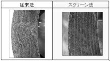
- squeezing wrinkles were generated in the carbon fiber felt layers laminated as shown in FIG. 2 by fastening the carbon fiber felt with sheet metal. It has been found that this drawing wrinkle not only deteriorates the appearance but also causes heat to escape along the drawing wrinkle, leading to a decrease in heat insulation performance. Furthermore, this method requires manual work by skilled workers and is not efficient.
- the method described in Patent Document 2 does not generate squeezing wrinkles, but it can be seen that when polypropylene or the like described in Patent Document 2 is used as a film, the lamination of carbon fiber felt peels off at the film portion after firing. It was.
- Patent Document 2 describes that the lamination of carbon fiber felts is integrated by a resin such as a phenolic resin existing between the laminations. It is disclosed that there is no particular limitation as long as it does not impair the adhesion of the laminate. However, it has been found that if the film is present between carbon fiber felt laminates, the film inhibits the integration of the carbon fiber felt laminate. This peeling of the carbon fiber felt not only reduces the commercial value in appearance but also has a drawback that the shape cannot be maintained during use.
- An object of the present invention is to provide a cylindrical carbon fiber-containing heat insulating material excellent in heat insulating performance without occurrence of squeezing wrinkles and peeling of carbon fiber felt, and a method for producing the same.
- the present invention [1] A hollow cylindrical fired wound body in which the fired carbon fiber felt layer is spirally wound and laminated, and an organic matter screen having a residual carbon ratio of 5% by weight or more between the fired carbon fiber felt layers.
- a fired wound body in which the laminates are bonded by having a fired organic screen layer fired [2] The fired wound body according to [1], wherein the fired organic screen is a fired cellulose-based screen layer, [3] The fired wound body according to [1], having a protective layer on the inner side surface and / or the outer side surface of the fired wound body, [4] A cylindrical heat insulating material including the fired wound body according to any one of [1] to [3], [5] (a) Step of impregnating carbon fiber felt with resin, (b) While applying tensile force to the organic screen having a residual carbon ratio of 5% by weight or more, the outer organic screen and the inner impregnated carbon fiber felt And a step of obtaining a hollow cylindrical pre-fired wound body by winding on a winding core, (c) a step of curing the obtained pre-fired wound body by heating, and (d) curing.
- a method for producing a hollow cylindrical fired wound body comprising a step of firing the wound body before firing, [6] The method for producing a fired wound body according to [5], wherein the organic screen is a cellulose screen. [7] The method for producing a fired wound body according to [5] or [6], wherein the basis weight of the organic screen is 50 to 600 g / m 2 , or [8] the organic screen in the winding step (b). Is a method of producing a fired wound body according to any one of [5] to [7], wherein the adhesive is applied. About.
- the cylindrical heat insulating material and the manufacturing method thereof according to the present invention since the drawing heat does not occur in the cylindrical heat insulating material, the heat insulating performance is not lowered by the drawing wrinkle. Further, since the carbon fiber felt laminates are firmly bonded by the organic screen, the carbon fiber felt is not peeled off, and the shape can be maintained during use. That is, according to the cylindrical heat insulating material and the manufacturing method thereof of the present invention, it is possible to obtain a cylindrical heat insulating material that is excellent in heat insulating performance and that can retain its shape during use.
- the firing winding body of the present invention is a hollow cylindrical firing wound body in which a fired carbon fiber felt layer is wound and laminated in a spiral shape. Are bonded by the baked organic screen layer.
- the fired organic matter screen layer is sandwiched between the spiral laminations of the fired carbon fiber felt layer.
- the screen layer plays a role of not bonding and peeling the laminated baked carbon fiber felt layers. Therefore, it is desirable that the screen is sandwiched over the entire area between the laminated layers of the baked carbon fiber felt layer.
- the baked organic matter screen layer is provided between the stacked layers. There may be parts that are not sandwiched.
- the area where the baked organic screen layer is sandwiched with respect to the total area between the laminated layers of the baked carbon fiber felt layer is preferably 50% or more, more preferably 70% or more, still more preferably 80% or more, 90% or more is more preferable, and 100% is most preferable.
- a fired wound body having an area between the fired organic screen layers of less than 100% can be manufactured, for example, by using an organic screen having regularly circular holes.
- the fired carbon fiber felt layer has no undulation in the laminated cross section and is wound and laminated.
- laminated without winding means that the baked carbon fiber felt is laminated without meandering, is laminated regularly, or is laminated without the wrinkles. Means.
- the fired wound body is used as a heat insulating material, it does not mean to eliminate slight swells, wrinkles, or meanders that do not greatly affect the heat insulating performance.
- the fired carbon fiber felt layer is obtained by firing a carbon fiber felt layer.
- the carbon fiber felt can be obtained by depositing carbon fibers uniformly and needle punching.
- As the raw material yarn of the carbon fiber felt for example, polyacrylonitrile-based (PAN-based) carbon fiber, pitch-based carbon fiber, or quinol carbon fiber (carbon fiber obtained by firing phenol resin fiber), or rayon-based carbon fiber, in particular, Can be used without restriction.
- the carbon fibers contained in the fired carbon fiber felt layer preferably have an average fiber diameter of 3 to 30 ⁇ m, more preferably 5 to 20 ⁇ m. If it is less than 3 ⁇ m, the production efficiency may decrease, and if it exceeds 30 ⁇ m, the heat insulation may decrease.
- the fiber length of the carbon fibers constituting the carbon fiber felt is preferably in the range of 30 to 500 mm, more preferably in the range of 50 to 250 mm. If it is less than 30 mm, the strength of the fired wound body may be weak. If it exceeds 500 mm, it is difficult to uniformly disperse the fibers, and it may be difficult to adjust the uniform carbon fiber felt.
- the thickness of one layer of the baked carbon fiber felt layer is not particularly limited, but is preferably 3 to 30 mm, and more preferably 3 to 20 mm. As another embodiment, it may be 4 to 30 mm or 4 to 20 mm.
- the carbon content of the baked carbon fiber felt is preferably 80% or more, more preferably 90% or more, still more preferably 95% or more, and most preferably 99% or more.
- the number of winding layers of the baked carbon fiber felt in the baked wound body of the present invention is not particularly limited, and can be appropriately determined depending on the application.
- the fired carbon fiber felt layer sandwiched between the two fired organic matter screen layers in the fired wound body of the present invention may be a single layer made of one fired carbon fiber felt or a multilayer of two or more layers.
- a layer in which two or more baked carbon fiber felts are combined a layer in which a baked carbon fiber felt and other carbonized screens are combined can be exemplified.
- Other carbonized screens are not limited as long as they do not cause peeling of the fired carbon fiber felt, and examples thereof include a fired organic screen layer.
- the baked organic matter screen layer is used to bond the laminated layers of the baked carbon fiber felt layers.
- the fired organic matter screen layer is not limited as long as it is obtained by firing an organic matter screen having a residual carbon ratio of 5% by weight or more.
- the residual carbon ratio of the organic matter screen is 5% by weight or more, preferably 10% by weight or more. When the residual carbon ratio is 5% by weight or more, the organic matter screen can increase the contact area between the baked carbon fiber felt layers and bond the baked carbon fiber felt layers together.
- the upper limit of the residual carbon ratio of the organic matter screen is not particularly limited as long as it does not hinder the bonding between the baked carbon fiber felt layers. For example, when a carbon fiber cloth is used, it is approximately 100% by weight. .
- the residual carbon ratio of the organic matter screen can also be estimated from the fired product between the fired carbon fiber felt layers after firing.
- the residual carbon ratio is less than 5% by weight, the fired product between the layers can hardly be observed.
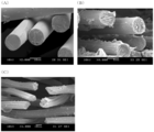
- the residual carbon ratio is 5% by weight or more, as shown in FIG. 3, it is possible to confirm the fired product of the organic matter screen (bleached cotton).
- the residual carbon ratio of the organic matter screen can be estimated from the porosity between the fired carbon fiber felt layers after firing.
- the thickness of the baked organic matter screen layer is not limited as long as the layers of the baked carbon fiber felt layers are bonded, but is preferably 0.01 mm to 3 mm, more preferably 0.01 mm to 2 mm, 0.05 Is more preferably from 1 to 1 mm, most preferably from 0.1 to 0.8 mm. Since processability will fall if it becomes too thick, it is preferable to set it as the said range. Further, the number of winding layers of the baked organic matter screen layer is not particularly limited, but is intended to catch the baked carbon fiber felt layer, and is therefore equal to or greater than the number of winding layers of the baked carbon fiber felt layer. .
- the fired organic screen layer sandwiched between two fired carbon fiber felt layers in the fired wound body of the present invention may be a single layer made of one fired organic screen, or may be a fired organic matter screen multilayer of two or more layers. In the case of a multilayer, mention may be made of two or more combinations selected from the group consisting of the cellulose-based screen layer, carbon fiber paper (carbon paper) screen layer, carbon fiber cloth (carbon cloth) screen layer, and rayon screen layer. Can do.
- the fired cellulose-based screen layer contained in the fired organic matter screen layer will be described below.
- Cellulose is a carbohydrate (polysaccharide) represented by the molecular formula (C 6 H 10 O 5 ) n and is the main component of cell walls and fibers of plant cells, but the calcined cellulose screen layer is mainly composed of cellulose.
- This is a layer obtained by firing a cellulose-based screen.
- firing includes a treatment for causing carbonization and a treatment for causing graphitization. Therefore, the fired cellulose-based screen layer may be a carbonized cellulose-based screen layer. It may be a system screen layer.
- the origin of the cellulosic screen is not limited as long as it contains cellulose, and examples thereof include cotton cloth (for example, bleached cloth and gauze), rayon, carbon fiber paper (carbon paper), and paper.
- the origin of the fired cellulose-based screen layer is cotton cloth (bleached cloth)
- a twisted structure by spinning can be observed.
- rayon derived from the fired cellulose-based screen layer a twisted structure by spinning can be observed.
- the pitch-based (A) and PAN-based (B) fibers shown in FIG. 4 have a twisted structure different from that of cotton cloth (bleached cloth) or rayon, and can be clearly distinguished.
- the baked cellulose contained in the baked cellulose-based screen layer is derived from a plant, it contains three isotopes having different masses of 12 C, 13 C, and 14 C as carbon.
- 12 C is about 98.9%
- 13 C is 1.1%
- 14 C is 1.2 ⁇ 10 ⁇ 10 %.
- 14 C is a radioisotope, a nuclide that decays naturally while emitting radiation, and has a half-life of 5730 years.
- 12 C and 13 C are stable isotopes and nuclides that do not cause decay. Therefore, petroleum carbon, which is believed to exist for over a million years, consists of 12 C and 13 C, and 14 C is not detected.
- the calcined carbon fiber felt layer is derived from petroleum or coal, it can be confirmed by measuring 14 C that the calcined wound body of the present invention includes a cellulose carbide screen layer. Is possible.
- the measurement method of 14 C is not particularly limited, and examples thereof include a radiation measurement method or a method using an acceleration mass spectrometer (AMS).
- AMS method The method used (hereinafter referred to as AMS method) is preferred.
- AMS method a tandem accelerator is used, and carbon contained in a sample is ionized by a cesium cation. Ionized 12 C, 13 C, and 14 C are accelerated by a tandem accelerator, and a large amount of 12 C and 13 C are detected by a detector called a Faderer cup, and a trace amount of 14 C is detected by a heavy ion detector. Is done.
- the AMS method can detect 14 C from a sample of about 0.1 to 2 mg. By collecting the sample from between the laminated layers of the baked carbon fiber felt layer and confirming 14 C by the AMS method, It is possible to confirm whether or not a carbonized cellulose-based screen layer is included.
- the inner surface and outer surface of the fired wound body are not limited, but are preferably ground for dimensional processing.
- the inner surface of the baked wound body includes one or more baked organic screen layers, and preferably includes two baked organic screen layers.
- the fired organic matter screen layer on the inner surface is preferably ground for dimensional processing after firing, and the fired organic matter screen layer may be ground to be composed only of the fired carbon fiber felt layer.
- the inner surface of the fired wound body may be either a fired carbon fiber felt layer alone, a fired organic matter screen layer alone, or a combination thereof. It is preferable that the material is composed of only the material having a smooth surface.
- the number of the baked organic matter screen layers is not limited, and may be one or more layers.
- the outer surface of the fired wound body is also preferably ground after firing, and the fired organic matter screen layer may be ground to be composed only of the fired carbon fiber felt layer or a combination thereof. Therefore, the outer surface of the fired wound body may be either a fired carbon fiber felt layer alone, a fired organic screen layer alone, or a combination thereof. It is preferable to have a smooth surface. Moreover, when it consists only of a baked organic matter screen layer, the number of the baked organic matter screen layers is not limited, and may be one or more layers.
- the calcined carbon fiber felt layer is more than 0% and less than 100%
- the calcined organic screen layer is more than 0% and less than 100%. That is, it is not limited as long as it consists of a combination of a baked carbon fiber felt layer and a baked organic screen layer.
- the fired wound body of the present invention may have a protective layer on the inner surface or outer surface thereof.
- a protective layer for example, a graphite sheet, a carbon fiber fabric, a hybrid carbon fiber fabric, or the like may be attached.
- what coated special coating agent on the inner surface or the outer surface may be used.
- OS coating or PG coating can be mentioned.
- the graphite sheet is not particularly limited as long as it is airtight and flexible and does not shrink even when exposed to high temperatures.
- the graphite sheet can be produced by aligning the orientations in the parallel direction by applying pressure from one direction at a high temperature and pressing.
- the raw material of the graphite sheet is not particularly limited and may be either natural graphite or artificial graphite.
- the carbon fiber fabric layer is not particularly limited as long as carbon fiber spun yarn is woven.
- carbon fiber spun yarn spun yarn made of polyacrylonitrile (PAN) carbon fiber, spun yarn made of pitch anisotropic carbon fiber, spun yarn made of rayon carbon fiber, or pitch isotropic Mention may be made of spun yarn made of carbon fiber.
- the hybrid carbon fiber fabric layer is not limited as long as it is woven with hybrid carbon fiber spun yarn.
- Hybrid carbon fiber spun yarn includes spun yarn made of polyacrylonitrile (PAN) carbon fiber, spun yarn made of pitch anisotropic carbon fiber, spun yarn made of rayon carbon fiber, and pitch isotropic carbon fiber.
- the OS coat is for coating a base material of a heat insulating material with a coating agent containing a specific carbonized material and / or graphite powder (hereinafter sometimes referred to as an OS coating agent), and is excellent in a heat insulating material. Surface smoothness, surface glossiness, and sufficiently low gas permeability can be imparted. Furthermore, it is possible to impart excellent dusting prevention properties and oxidation resistance to the heat insulating material on which the coating layer for heat insulating material is laminated. As the graphite powder, scaly graphite powder is preferable.
- the PG coat coats pyrolytic carbon on a base material of a heat insulating material, and imparts excellent oxidation resistance, gas impermeability, mechanical strength, and dust generation suppressing effect to the heat insulating material. For example, it is possible to prevent the reaction between the SiO gas or the Si gas and the cylindrical carbon fiber felt base material.
- the ratio of the baked carbon fiber felt layer and the baked organic screen layer in the cross section of the cylinder of the baked wound body that is, the area ratio of the baked carbon fiber felt layer and the baked organic screen layer in the cross section is not particularly limited.
- the felt layer is 80% to 99.9%
- the screen layer is 0.1% to 20%, more preferably the felt layer is 95% to 99.5%, and the screen layer is 0.5%. % To 5%.
- the size of the fired wound body of the present invention is appropriately determined depending on its use and is not particularly limited.
- the height is, for example, 10 to
- the outer diameter (diameter) is 200 to 200 cm
- the inner diameter (diameter) is 30 to 190 cm.
- the difference between the outer diameter and the inner diameter, that is, the thickness of the fired wound body can also be determined as appropriate, but when used as a heat insulating material, it is usually preferably in the range of 5 to 500 mm, more preferably in the range of 10 to 300 mm. It is because productivity will fall when the thickness of a baking wound body is too thick, and heat insulation will fall when too thin.
- the fired wound body of the present invention has a hollow cylindrical shape, but the cross-sectional shape may be a perfect circle or an ellipse. That is, the cross section of the outer surface and the cross section of the inner surface may be a perfect circle or an ellipse.
- the bulk density of the fired wound body of the present invention is not particularly limited, but is preferably in the range of 0.07 to 0.40 g / cm 3 , and more preferably in the range of 0.10 to 0.30 g / cm 3. preferable. If it is less than 0.05 g / cm 3, the heat insulating property is lowered, and when it exceeds 0.40 g / cm 3, insulation resistance decreases.
- the fired wound body of the present invention is fired.
- carbonization occurs by firing a carbonizable carbon precursor at 650-1500 ° C.
- graphitization occurs by firing at 1500-3000 ° C.
- the “firing” in this specification includes a heat treatment in which carbonization occurs and a heat treatment in which graphitization occurs.
- the fired wound body includes a carbonized one and a graphitized one, but when used as a heat insulating material, the graphitized one has a high purity and a small amount of generated gas at the time of use. It is preferable at the point which is excellent in high temperature stability.
- the cylindrical heat insulating material of the present invention includes the fired wound body.
- a fired wound body comprising a fired carbon fiber felt layer and a fired organic matter screen layer can be used as it is.
- a fired wound body having the protective layer may be used.
- the cylindrical heat insulating material of the present invention can be used as a cylindrical carbon fiber-containing heat insulating material for a high temperature furnace. Specifically, it can be used as a heat insulating material in a vacuum furnace, a semiconductor single crystal growth furnace, a ceramic sintering furnace, or a C / C composite firing furnace. Since the heat insulating material of the present invention has no undulation of the carbon fiber felt, the heat insulating performance is excellent. That is, the carbon fiber felt is laminated without wrinkling and has excellent heat insulation performance.
- the manufacturing method of the fired wound body of the present invention includes (a) a step of impregnating a carbon fiber felt with a resin, and (b) pulling an organic screen having a residual carbon ratio of 5% by weight or more A step of obtaining a hollow cylindrical pre-fired wound body by layering an outer organic screen and the inner impregnated carbon fiber felt while applying force, and winding the wound core around a winding core; A step of curing the wound body before firing by heating, and (d) a step of firing the wound body before firing.
- the multi-layering can be performed by applying an impregnation felt thereon while applying a tensile force to the organic screen.
- the organic screen is preferably coated with a resin (adhesive) in order to increase the strength.
- the resin-impregnated carbon fiber felt obtained in the impregnation step (a) may be wound as it is in the winding step (b). However, in the impregnation step (a), after the resin-impregnated carbon fiber felt is dried and the solvent is volatilized to reduce the solvent amount of the resin-impregnated carbon fiber felt, the winding step (b) May be implemented.
- the fired wound body or cylindrical heat insulating material of the present invention can be produced by the method for producing a fired wound body of the present invention.
- Carbon fiber felt As the raw material yarn of the carbon fiber felt used in the fired wound body of the present invention, for example, polyacrylonitrile (PAN) carbon fiber, pitch carbon fiber, quinol carbon fiber, or rayon carbon fiber, in particular, Can be used without restriction.
- PAN polyacrylonitrile
- the carbon fiber felt can be obtained by needle punching the raw yarn.
- the carbon fiber preferably has an average fiber diameter of 5 to 20 ⁇ m, more preferably 8 to 18 ⁇ m. If it is less than 5 ⁇ m, the production efficiency may decrease, and if it exceeds 20 ⁇ m, the heat insulation may decrease.
- the fiber length of the carbon fibers constituting the carbon fiber felt is preferably in the range of 30 to 500 mm, more preferably in the range of 50 to 250 mm. If it is less than 30 mm, the strength of the cylindrical carbon fiber-containing laminate may be weak, and if it exceeds 500 mm, it is difficult to uniformly disperse the fibers and it may be difficult to make a uniform felt.
- the thickness of the carbon fiber felt is not particularly limited, but is preferably 3 to 30 mm, and more preferably 2 to 20 mm. Further, as another aspect, it may be 5 to 30 mm or 10 to 30 mm.
- the carbon content of the carbon fiber felt is preferably 80% or more, more preferably 90% or more, and most preferably 95% or more.
- the bulk density of the carbon fiber felt is preferably in the range of 0.01 ⁇ 0.13g / cm 3, more preferably in the range of 0.02 ⁇ 0.10g / cm 3. When it is less than 0.01 g / cm 3, it is difficult to produce a cylindrical carbon fiber-containing laminate, while it is difficult to produce a carbon fiber felt that exceeds 0.13 g / cm 3 , both of which have productivity. descend.
- thermosetting resin An example of the resin impregnated in the carbon fiber felt is a thermosetting resin.
- the thermosetting resin include urea resin, melamine resin, phenol resin, epoxy resin, unsaturated polyester resin, alkyd resin, urethane resin, furan resin, and the like, and a phenol resin having a high carbonization yield is preferable.
- the amount of the resin impregnated in the carbon fiber felt is preferably 10 to 100 parts by mass, more preferably 15 to 50 parts by mass with respect to 100 parts by mass of the carbon fiber felt.
- the organic matter screen used for the cylindrical carbon fiber-containing laminate of the present invention is not particularly limited as long as the residual carbon ratio is 5% by weight or more.
- the residual carbon ratio of the organic matter screen is 5% by weight or more, preferably 10% by weight or more. When the residual carbon ratio is 5% by weight or more, the organic matter screen can increase the contact area between the baked carbon fiber felt layers and bond the baked carbon fiber felt layers together.
- the upper limit of the residual carbon ratio of the organic matter screen is not particularly limited as long as it does not hinder the bonding between the laminated layers of the baked carbon fiber felt layer, but is 100% by weight or less, for example.
- the organic screen may contain substances other than organic substances (for example, inorganic substances) as long as the residual carbon ratio is 5% by weight or more.
- the organic screen and the adhesive are carbonized by firing.
- the cellulosic screen together with the adhesive can increase the contact area between the carbon fiber felt layers.
- the organic screen plays a role of assisting the winding of the carbon fiber felt when the fired wound body is manufactured as described above. Accordingly, it is preferable to have a breaking strength of a certain level or more.
- the lower limit of the breaking strength is preferably 100 N / 5 cm or more, more preferably 200 N / 5 cm or more, and further preferably 300 N / 5 cm or more. And most preferably 400 N / 5 cm or more.
- the breaking strength can be improved by applying an adhesive to the screen, and the lower limit of the breaking strength of the organic screen coated with the adhesive is preferably 300 N / 5 cm or more, more preferably 500 N / 5 cm or more.
- breaking strength is too low, it will not be able to play the role of assisting the winding of the carbon fiber felt, and the higher the height (width) of the cylindrical laminate, the higher the outer diameter of the cylindrical laminate becomes higher. This is because tensile tension is required.
- the upper limit of breaking strength is not specifically limited irrespective of the presence or absence of an adhesive agent.
- the thickness of the organic screen is not particularly limited as long as it has a constant breaking strength, but is preferably 0.01 mm to 3 mm, more preferably 0.01 mm to 2 mm, and most preferably 0.05 to 1 mm. As another aspect, it may be 0.05 mm to 4 mm, 0.1 to 2 mm, or 0.2 to 1 mm. If the thickness is too large, the workability and the felt interlayer adhesion strength are lowered, and therefore it is preferably within the above range.
- the organic matter basis weight (FAW) is not particularly limited as long as it has a certain breaking strength, but is preferably 50 to 600 g / m 2 , more preferably 70 to 500 g / m 2 , 80 to 300 g / m 2 is preferable.
- the cellulose screen used in the cylindrical carbon fiber-containing laminate of the present invention is not particularly limited as long as it contains cellulose, but preferably contains 50% by mass or more of cellulose, and contains 70% by weight or more. More preferably, those containing 95% by weight or more are most preferable.
- Cellulose is a carbohydrate (polysaccharide) represented by the molecular formula (C 6 H 10 O 5 ) n and is the main component of the cell wall and fiber of plant cells.
- the residual carbon ratio of the cellulosic screen is 5% or more, preferably 6% or more, and more preferably 7% or more. This is because when the residual carbon ratio is 1% or more, the carbonized cellulose-based screen serves to increase the contact area between the baked carbon fiber felt layers.
- examples of the cellulosic screen include cotton cloth (for example, bleached cloth, gauze), rayon, or paper, and cotton cloth is particularly preferable.
- the preferred range of breaking strength, thickness, and basis weight when using a cotton cloth as the cellulosic screen is the same as that of the organic screen.
- the carbon fiber felt and the organic screen used in the method for producing a fired wound body of the present invention may be bonded with an adhesive.
- the adhesive may be applied to both the carbon fiber felt and the organic screen, or may be applied to either one.
- the breaking strength can be increased by applying an adhesive to the organic screen.
- the amount of the adhesive, with respect to organic matter screen preferably 50 ⁇ 3000g / m 2, more preferably 100 ⁇ 1000g / m 2, and most preferably 100 ⁇ 500g / m 2.
- the adhesive As a method for applying the adhesive, a normal method can be used.
- the adhesive can be applied with a spatula, a brush, a roller, or the like.
- the organic screen a screen obtained by previously applying an adhesive and drying it to remove volatile components may be used. Moreover, you may wind, apply
- the drying temperature when the adhesive is previously applied to the organic screen is not limited, but can be 60 to 150 ° C.
- the adhesive used for the cylindrical carbon fiber-containing laminate of the present invention is carbonized by firing, it preferably contains a large amount of carbon, but is not particularly limited by the carbon content. Specifically, 60 to 100 parts by mass of thermosetting prepolymer, 20 to 60 parts by mass of thermosetting resin; 5 to 20 parts by mass of short carbon fiber, carbon black, carbon powder or graphite powder; An adhesive composition in which 5 parts by mass of water and 5 to 20 parts by mass of water are uniformly mixed and dispersed can be used.
- the residual carbon ratio of the adhesive is not particularly limited, but is 20 to 95% by weight, preferably 30 to 85% by weight, and more preferably 40 to 75% by weight. When the residual carbon ratio is 20% or more, the contact area can be increased between the baked carbon fiber felt layers.
- thermosetting prepolymers urea resin prepolymers; melamine resin prepolymers, urea-modified melamine resin prepolymers; guanamine resin prepolymers; guanamine-modified melamine resin prepolymers; furan resin prepolymers; alkyd resin prepolymers; Polymers such as novolac type phenol resin prepolymers, resol type phenol resin prepolymers, novolac type alkyl phenol resin prepolymers, resol type alkylphenol resin prepolymers and their xylene / formaldehyde condensates, toluene / formaldehyde condensates, or melamine resins, guanamines Modified resin prepolymer with resin or urea resin; epoxy resin prepolymer such as bisphenol A diglycidyl ether, alicyclic Diglycidyl ethers of alcohols, bisphenol A bis (alpha-methyl glycidyl ether),
- a resin prepolymer having a high carbonization yield is preferable, and a novolak type phenol resin prepolymer, a resol type phenol resin prepolymer, a novolac type alkylphenol resin prepolymer, and a resol type alkylphenol resin prepolymer can be particularly preferably used.
- Thermosetting resins include urea resins; melamine resins; urea-modified melamine resins; guanamine resins; guanamine-modified melamine resins; alkyd resins; furan resins; unsaturated polyester resins; phenol resins such as novolak-type phenol resins and resol-type phenol resins.
- Novolac-type alkylphenol resins Novolac-type alkylphenol resins, resol-type alkylphenol resins; epoxy resins such as bisphenol A diglycidyl ether, alicyclic dialcohol diglycidyl ether, bisphenol A bis ( ⁇ -methylglycidyl ether), alicyclic dialcohol bis ( Preferred examples include ⁇ -methyl glycidyl ether).
- resins having a high carbonization yield are preferable, and novolak-type phenol resins, resol-type phenol resins, novolac-type alkylphenol resins, and resol-type alkylphenol resins can be particularly preferably used.
- acetone methyl ethyl ketone, methyl isobutyl ketone, methanol, ethanol, 2-furylmethanol, toluene, xylene, dimethyl sulfoxide, or the like can be preferably used.
- Impregnation step (a) In the impregnation step (a) in the production method of the present invention, a carbon fiber felt is impregnated with a resin.
- a resin impregnated in the carbon fiber felt is a thermosetting resin.
- the thermosetting resin include urea resin, melamine resin, phenol resin, epoxy resin, unsaturated polyester resin, alkyd resin, urethane resin, furan resin, and the like, and a phenol resin having a high carbonization yield is preferable.
- the amount of the resin impregnated in the carbon fiber felt is preferably 10 to 100 parts by mass, more preferably 15 to 50 parts by mass with respect to 100 parts by mass of the carbon fiber felt.
- the impregnation method can be performed according to a known method, for example, a dipping method or a spray coating method.
- the resin is dispersed in a solvent, and the resin is impregnated into the carbon fiber felt by a dipping method or a spray coating method.
- the solvent is not particularly limited, and examples thereof include methanol, ethanol, methyl ethyl ketone (MKE), or a combination of two or more thereof.
- MKE methyl ethyl ketone
- the resin-impregnated carbon fiber felt obtained in the impregnation step (a) may be wound as it is in the winding step (b). However, in the impregnation step (a), the resin-impregnated carbon fiber felt may be dried in order to volatilize the solvent contained in the carbon fiber felt.
- the drying temperature is not particularly limited, but may be, for example, 60 to 200 ° C., preferably 110 to 170 ° C.
- the drying time is not particularly limited, but may be, for example, 1 to 48 hours, and preferably 2 to 12 hours.
- winding step (b) the carbon fiber felt impregnated with the resin and the organic screen are layered and wound with a winding machine to obtain a wound body before firing.
- An example of the winding step (b) will be described with reference to FIG.
- a carbon fiber felt (1) impregnated with resin is set.
- the organic screen is set by applying an adhesive and drying it.
- the organic screen (2) coated with an adhesive is mounted on the winding core (4) of the winding machine (3).
- the attached organic screen is pre-wound around the winding core 1-2 times.
- the winder is temporarily stopped, and the end of the carbon fiber felt is mounted so as to be inserted between the organic matter screen and the winder core of the winder.
- the carbon fiber felt and the organic matter screen are wound up with a winder while applying the organic matter tensile tension without applying a tensile tension to the carbon fiber felt.
- the thickness of the wound body is measured by a thickness sensor (5) installed outside the winder, and the optimum tensile tension is applied to the organic matter screen according to the thickness of the wound body, thereby adjusting the density of the wound body. Keep it constant.
- the carbon fiber felt and the organic matter screen are cut. In this case, the carbon fiber felt may be cut first, and the organic matter screen may be further wound after 2-3 turns.
- the adhesive when the adhesive is not previously applied to the cellulosic screen, the adhesive may be applied to the cellulosic screen outside the winder with an adhesive brush (not shown).
- the number of times of preliminary winding or subsequent winding of the organic screen is not particularly limited, but is preferably 0.5 to 10, and more preferably 1 to 5.
- the obtained carbon fiber felt and screen winding are cured by heating.
- the heating temperature is not limited as long as the resin impregnated in the carbon fiber felt is cured, but it can be performed at, for example, 100 to 200 ° C. Furthermore, the heating time can also be defined as appropriate. Depending on the stack thickness (number of stacks), for example, it can be performed in 10 minutes to 20 hours.
- Heating can be performed with steam or a high-temperature furnace (air circulation or the like).
- the firing step (d) can be performed at 3000 ° C. or less in a non-oxidizing atmosphere.
- the non-oxidizing atmosphere include a vacuum state, a nitrogen atmosphere, and an argon atmosphere.
- the temperature is not particularly limited as long as it causes carbonization, but is preferably 650 to 3000 ° C, more preferably 1000 to 3000 ° C. Further, when graphitization is required, 2000 ° C. to 3000 ° C. is preferable.
- the obtained fired wound body can be used as a heat insulating material as it is, but the inner surface, outer surface, both ends (both ends in the width direction of the felt) of the wound body, or a combination of two or more thereof are ground. Is preferred.
- a grinding method a known method can be used. For example, grinding can be performed using a lathe or a machining center. It can be processed into a predetermined dimension by grinding.
- Example 1 In this example, a pre-firing wound body was manufactured using the winder shown in FIG. Carbon fiber felt (bulk density 0.08 g / cm 3 , thickness 16 mm; Klecafelt: Kureha Co.) 100 parts by weight, phenol resin (Shonol BRS-3897: Showa Denko Co., Ltd.) 44 weight Part was impregnated.
- Carbon fiber felt bulk density 0.08 g / cm 3 , thickness 16 mm; Klecafelt: Kureha Co.
- phenol resin Shonol BRS-3897: Showa Denko Co., Ltd.
- an adhesive J-325: manufactured by DIC, OI-305A: solution prepared by mixing DIC manufactured at 6: 4
- was bleached (count: 50 ⁇ 50, basis weight: 105 g / cm 2 , number of shots 144 ⁇ 76 pieces / ⁇ ; 5555-P: manufactured by Tokyo Sugimoto Co., Ltd.) at 220 g / m 2 and dried at 110 ° C.
- a dry cloth coated with an adhesive and dried was set on a supply roller.
- the bleached cloth was set on the winding core of the winder and wound once in advance.
- the end of the carbon fiber felt impregnated with the phenol resin was inserted between the winding core of the winder and the bleaching cloth.
- FIG. 2 shows a cross-sectional view of the wound body before firing, and it can be seen that the carbon fiber felts are regularly and laminated.
- Example 2 Instead of applying the adhesive in advance to the bleached cloth, the operation of Example 1 was repeated except that it was applied with a brush at the time of winding to obtain a fired wound body. Note that an adhesive (EXP-30) was applied to the bleached cloth so as to be 500 g / m 2 with a brush.
- an adhesive EXP-30
- Comparative Example 1 Carbon fiber felt (bulk density 0.08 g / cm 3 , thickness 16 mm; Klecafelt: Kureha Co.) 100 parts by weight, phenol resin (Shonol BRS-3897: Showa Denko Co., Ltd.) 44 weight Part was impregnated. The carbon fiber felt impregnated with the phenol resin was set on the winding core of the winder, and the carbon fiber felt was wound with the winder. When the number of windings of the laminate reached 10 times, the winding was finished, and the winding core and the wound body were removed from the winding machine. The obtained wound body was clamped to a thickness of 82 mm with a sheet metal and then cured by treatment at 140 ° C. for 8 hours.
- the fired wound body was obtained by removing the cured wound body before firing from the winding core and firing at 2000 ° C. for 1 hour under vacuum. After firing, the inner and outer surfaces were ground by a machining center. The resulting fired wound body had a bulk density of 0.152 g / cm 3 .
- FIG. 2 shows a cross-sectional view of the laminate before firing. Unlike Example 1, it can be seen that the carbon fiber felt swells and wrinkles are generated.
- Comparative Example 2 Instead of bleached cloth, use cold polypropylene of polypropylene (thickness: 0.24 mm, weight per unit: 50 g / m 2 , number of shots: 34 x 25 x ⁇ / PF; PF-200: manufactured by Otsuka Kogyo Co., Ltd.) The procedure of Example 1 was repeated, except that there was. In the obtained fired wound body, peeling between the fired carbon fiber felt layers was observed.
- the tensile strength (MPa) of the sample was obtained by peeling the test piece at a tensile speed of 1.0 mm / min and measuring the load (N). The results are shown in Table 2.
- the carbon residue rate of each screen was measured by quantifying the carbon content of the ignition residue after the sample was ignited in an inert gas.
- the strong heat is obtained by putting approximately 1 g of volatile organic substances (this exact weight is W 1 (g)) into a crucible and flowing the crucible in an electric furnace at 10 ° C./min. The temperature was raised to 0 ° C. and then ignited at 800 ° C. for 1 hour.
- the residue at this time was regarded as an ignition residue, and its weight was defined as W 2 (g).
- the ignition residue was subjected to elemental analysis in accordance with the method defined in JIS M8819, and the carbon weight ratio P 1 (%) was measured.
- the residual coal rate P 2 (%) was calculated by the following formula.
- the cylindrical carbon fiber-containing heat insulating material of the present invention can be used as a heat insulating material in a vacuum furnace, a semiconductor single crystal growth furnace, a ceramic sintering furnace, or a C / C composite firing furnace. Further, according to the method for producing a fired cylindrical carbon fiber-containing laminate of the present invention, a cylindrical carbon fiber-containing heat insulating material having excellent heat insulation performance can be produced without requiring a skilled technique. As mentioned above, although this invention was demonstrated along the specific aspect, the deformation
Landscapes
- Engineering & Computer Science (AREA)
- Mechanical Engineering (AREA)
- General Engineering & Computer Science (AREA)
- Chemical & Material Sciences (AREA)
- Ceramic Engineering (AREA)
- Composite Materials (AREA)
- Textile Engineering (AREA)
- Laminated Bodies (AREA)
- Inorganic Fibers (AREA)
- Thermal Insulation (AREA)
- Carbon And Carbon Compounds (AREA)
Abstract
Description
この炭素繊維フェルトを用いた円筒型の断熱材の製造方法として、特許文献1には炭素繊維フェルトに炭化可能な樹脂を含浸させ、含浸フェルトを積層圧縮しつつ目的の厚さと嵩密度とを有する成形断熱材の製造方法が開示されている。具体的には、樹脂を含浸させた炭素繊維フェルトを金属の型に巻き付け、外側から板金により締め付け炭素繊維フェルトを圧縮成形し炭化させる方法が開示されている。
一方、特許文献2には、炭素繊維フェルトとフィルム等とを、フィルム等に張力を作用させながら、巻取体で巻き取り、目的の嵩密度の炭素繊維フェルト及びフィルムからなる積層体を作製し、その積層体を焼成することにより、円筒型の断熱材を製造する方法が開示されている。
一方、特許文献2に記載の方法は、絞りジワの発生はないが、フィルムとして特許文献2に記載のポリプロピレン等を用いると、焼成後にフィルムの部分で炭素繊維フェルトの積層が剥離することがわかった。特許文献2には、炭素繊維フェルトの積層は、その積層間に存在するフェノール樹脂などの樹脂によって、一体化することが記載されており、炭素繊維フェルトの積層間に存在するフィルム等は、フェルトの積層の接着性を損なわないものであれば、特に限定されないことが開示されている。しかしながら、フィルムが炭素繊維フェルトの積層間に存在する場合、フィルムが炭素繊維フェルト積層の一体化を阻害することが分かった。この炭素繊維フェルトの剥離は、外見的に商品価値を低下させるのみではなく、使用時に形状を保持できなくなる欠点を有する。
本発明の目的は、絞りジワ及び炭素繊維フェルトの剥離の発生がなく、断熱性能の優れた円筒型の炭素繊維含有断熱材及びその製造方法を提供することである。
本発明は、こうした知見に基づくものである。
従って、本発明は、
[1]焼成炭素繊維フェルト層が、らせん状に巻回積層している中空円筒状の焼成巻回体であって、焼成炭素繊維フェルト層の積層間に残炭率5重量%以上の有機物スクリーンが焼成された焼成有機物スクリーン層を有することにより、前記積層間が結合されている焼成巻回体、
[2]前記焼成有機物スクリーンが、焼成セルロース系スクリーン層である、[1]に記載の焼成巻回体、
[3]焼成巻回体の内側面及び/又は外側面に保護層を有する、[1]に記載の焼成巻回体、
[4][1]~[3]のいずれかに記載の焼成巻回体を含む円筒状断熱材、
[5](a)炭素繊維フェルトに樹脂を含浸させる工程、(b)残炭率5重量%以上の有機物スクリーンに引張力を付与しながら、外側の有機物スクリーンと内側の前記含浸炭素繊維フェルトとを重層して巻取芯に巻回することによって中空円筒状の焼成前巻回体を得る工程、(c)得られた焼成前巻回体を加熱により硬化させる工程、及び(d)硬化した焼成前巻回体を焼成する工程、を含むことを特徴とする中空円筒状の焼成巻回体の製造方法、
[6]前記有機物スクリーンが、セルロース系スクリーンである、[5]に記載の焼成巻回体の製造方法、
[7]前記有機物スクリーンの目付けが50~600g/m2である、[5]又は[6]に記載の焼成巻回体の製造方法、又は
[8]前記巻回工程(b)における有機物スクリーンが、接着剤の塗布されたものである、[5]~[7]のいずれかに記載の焼成巻回体の製造方法、
に関する。
本発明の焼成巻回体は、焼成炭素繊維フェルト層が、らせん状に巻回積層している中空円筒状の焼成巻回体であり、焼成炭素繊維フェルトの積層間が焼成有機物スクリーン層により結合しているものである。
本発明の焼成巻回体において、焼成炭素繊維フェルト層は積層断面でうねりがなく、巻回積層されたものである。本明細書において「うねりがなく巻回積層される」とは、焼成炭素繊維フェルトが蛇行せずに積層されていること、規則正しく積層されていること、又は前記絞りしわがなく積層されていることを意味している。しかしながら、焼成巻回体を断熱材として用いた場合に、断熱性能に大きな影響を与えない、わずかなうねり、しわ、又は蛇行を排除する意味ではない。
焼成炭素繊維フェルト層は、炭素繊維フェルト層が焼成されたものである。炭素繊維フェルトは、炭素繊維を均一に堆積し、ニードルパンチングすることによって得ることができる。炭素繊維フェルトの原料の原糸としては、例えばポリアクリロニトリル系(PAN系)炭素繊維、ピッチ系炭素繊維、又はカイノール炭素繊維(フェノール樹脂繊維を焼成した炭素繊維)、又はレーヨン系炭素繊維を、特に制限なく使用することができる。
焼成有機物スクリーン層は、焼成炭素繊維フェルト層の積層間を結合させるものである。焼成有機物スクリーン層は、残炭率が5重量%以上の有機物スクリーンを焼成したものである限りにおいて、限定されるものでないが、例えばセルロース系スクリーン層、炭素繊維紙(カーボンペーパー)スクリーン層、炭素繊維布(カーボンクロス)スクリーン層、又はレーヨン製スクリーン層を挙げることができる。
有機物スクリーンの残炭率は、5重量%以上であり、好ましくは10重量%以上である。残炭率が5重量%以上であることにより、有機物スクリーンが焼成炭素繊維フェルト層間で接触面積を増加させ、焼成炭素繊維フェルト層同士を結合させることができる。有機物スクリーンの残炭率の上限は、焼成炭素繊維フェルト層の積層間の結合を阻害しない限りにおいて、特に限定されるものではないが、例えば炭素繊維布を用いた場合、ほぼ100重量%である。
更に、有機物スクリーンの残炭率は、焼成後の焼成炭素繊維フェルト層の積層間の空隙率から推定することができる。
従って、百万年以上前から存在していると考えられている石油の炭素は、12C、及び13Cからなり、14Cは検出されない。すなわち、石油ピッチ由来の炭素繊維から製造された焼成炭素繊維フェルト層の場合、12C及び13Cのみが検出され、14Cは検出されない。一方、現在の植物のセルロース由来である焼成セルロース系スクリーン層に含まれる炭素として、12C及び13C以外に、14Cが検出される。従って、焼成炭素繊維フェルト層が石油由来又は石炭由来である場合は、14Cを測定することによって、本発明の焼成巻回体に炭化セルロース系スクリーン層が含まれていることを確認することが可能である。
焼成巻回体の内面及び外面は、限定されるものではないが、寸法加工のために研削することが好ましい。焼成巻回体の内面は、1層以上の焼成有機物スクリーン層を含み、好ましくは2層の焼成有機物スクリーン層を含む。前記のように内面の焼成有機物スクリーン層は焼成後に寸法加工のために研削することが好ましく、焼成有機物スクリーン層が研削され、焼成炭素繊維フェルト層のみからなるものでもよい。
従って、前記焼成巻回体の内面は、焼成炭素繊維フェルト層のみからなるもの、焼成有機物スクリーン層のみからなるもの、又はそれらの組み合わせからなるもののいずれでもよいが、外見からは焼成炭素繊維フェルト層のみからなるものが、表面がなめらかであり好ましい。また、焼成有機物スクリーン層のみからなる場合、その焼成有機物スクリーン層の数は限定されず、1又は2層以上であってよい。
従って、前記焼成巻回体の外面は、焼成炭素繊維フェルト層のみからなるもの、焼成有機物スクリーン層のみからなるもの、又はそれらの組み合わせからなるもののいずれでもよいが、外見からは炭素繊維フェルト層のみからなるものが、表面がなめらかであり好ましい。また、焼成有機物スクリーン層のみからなる場合、その焼成有機物スクリーン層の数は限定されず、1又は2層以上であってよい。
前記黒鉛シートは、気密性、可撓性があり、かつ高温にさらされても収縮しないものであれば、特に限定されるものではない。黒鉛シートは、高温下で一方向から力を加え加圧成形することで、配向を平行方向に揃え、作製することができる。黒鉛シートの原材料も、特に限定されず天然黒鉛と人造黒鉛のどちらでもよい。
前記炭素繊維織物層は、炭素繊維紡績糸を織成したものであれば特に限定されるものではない。例えば、炭素繊維紡績糸としては、ポリアクリロニトリル系(PAN系)炭素繊維からなる紡績糸、ピッチ系異方性炭素繊維からなる紡績糸、レーヨン系炭素繊維からなる紡績糸、又はピッチ系等方性炭素繊維からなる紡績糸を挙げることができる。
前記ハイブリッド炭素繊維織物層は、ハイブリッド炭素繊維紡績糸によって織成される限りにおいて限定されない。ハイブリッド炭素繊維紡績糸は、ポリアクリロニトリル系(PAN系)炭素繊維からなる紡績糸、ピッチ系異方性炭素繊維からなる紡績糸、レーヨン系炭素繊維からなる紡績糸、及びピッチ系等方性炭素繊維のいずれかの紡績糸の組み合わせからなるものである。
前記OSコートとは、特定の炭素化材及び/又は黒鉛粉末を含むコーティング剤(以下、OSコーティング剤と称することがある)を断熱材の基材に被覆するものであり、断熱材に優れた表面平滑性と、表面光沢性と、十分に低いガス透過性とを付与できるものである。更に、その断熱材用コーティング層が積層された断熱材に優れた発塵防止性、及び耐酸化性を付与することが可能である。黒鉛粉末としては、好ましくは鱗状黒鉛粉末を挙げることができる。
前記PGコートとは、熱分解炭素を断熱材の基材に被覆するものであり、断熱材に優れた耐酸化性、気体不浸透性、機械的強度、及び発塵抑制効果を付与することが可能であり、例えばSiOガス又はSiガスと、円筒状炭素繊維フェルト基材とが反応することを防止することができる。
本発明の焼成巻回体は焼成されたものである。一般的には、炭素化可能な炭素前駆体を650~1500℃で焼成することによって炭素化が起き、1500~3000℃で焼成することによって黒鉛化がおきる。本明細書における「焼成」は炭素化の起きる熱処理、及び黒鉛化の起きる熱処理を含む。従って、焼成巻回体は、炭素化されたもの、及び黒鉛化されたものを含むが、断熱材として用いる場合は、黒鉛化されたものが、高純度で使用時の発生ガス量が少なく、高温安定性に優れる点で好ましい。
本発明の円筒状断熱材は前記焼成巻回体を含むものである。円筒状断熱材として用いる場合、焼成炭素繊維フェルト層と焼成有機物スクリーン層からなる焼成巻回体をそのままもちいることもできる。一方、前記保護層を有する焼成巻回体を用いてもよい。本発明の円筒状断熱材は、高温炉の円筒型炭素繊維含有断熱材として使用することができる。具体的には、真空炉、半導体単結晶成長炉、セラミックス焼結炉、又はC/Cコンポジット焼成炉の炉内の断熱材として用いることができる。
本発明の断熱材は、炭素繊維フェルトの積層のうねりがないため、断熱性能が優れている。すなわち、炭素繊維フェルトが絞りしわがなく積層されており、断熱性能が優れている。
本発明の焼成巻回体の製造方法は、(a)炭素繊維フェルトに樹脂を含浸させる工程、(b)残炭率5重量%以上の有機物スクリーンに引張力を付与しながら、外側の有機物スクリーンと内側の前記含浸炭素繊維フェルトとを重層して巻取芯に巻回することによって中空円筒状の焼成前巻回体を得る工程、(c)得られた焼成前巻回体を加熱により硬化させる工程、及び(d)硬化した焼成前巻回体を焼成する工程、を含むことを特徴とするものである。前記重層は、図1に示すように、有機物スクリーンに引張力を付与しながら、その上に含浸フェルトを重層して行うことができる。更に、前記有機物スクリーンは、強度を上昇させるために、樹脂(接着剤)を塗工することが好ましい。
また、前記含浸工程(a)で得られた樹脂含浸炭素繊維フェルトは、そのまま巻回工程(b)において、巻回してもよい。しかしながら、前記含浸工程(a)において、前記樹脂含浸炭素繊維フェルトを乾燥させる処理を行い、溶媒を揮発させることによって、樹脂含浸炭素繊維フェルトの溶媒量を減少させた後に、巻回工程(b)を実施してもよい。
本発明の焼成巻回体の製造方法によって、本発明の焼成巻回体又は円筒状断熱材を製造することができる。
本発明の焼成巻回体に用いられる炭素繊維フェルトの原料の原糸としては、例えばポリアクリロニトリル系(PAN系)炭素繊維、ピッチ系炭素繊維、又はカイノール炭素繊維、又はレーヨン系炭素繊維を、特に制限なく使用することができる。炭素繊維フェルトは、前記原糸をニードルパンチングすることによって得ることができる。
炭素繊維フェルトの嵩密度は、0.01~0.13g/cm3の範囲が好ましく、0.02~0.10g/cm3の範囲が更に好ましい。0.01g/cm3未満であると、円筒型炭素繊維含有積層体の製造が困難であり、一方、0.13g/cm3を超える炭素繊維フェルトの製造は困難であり、いずれも生産性が低下する。
前記炭素繊維フェルトに含浸させる樹脂としては熱硬化性樹脂を挙げることができる。熱硬化性樹脂としては、尿素樹脂、メラミン樹脂、フェノール樹脂、エポキシ樹脂、不飽和ポリエステル樹脂、アルキド樹脂、ウレタン樹脂、フラン樹脂などを挙げることができるが、炭化歩留まりの高いフェノール樹脂が好ましい。炭素繊維フェルトに対する樹脂の含浸量は、炭素繊維フェルト100質量部に対して、10~100質量部が好ましく、15~50質量部がより好ましい。
本発明の円筒型炭素繊維含有積層体に用いられる有機物スクリーンは、残炭率が5重量%以上であれば、特に限定されないが、例えばセルロース系スクリーン、炭素繊維紙(カーボンペーパー)スクリーン、炭素繊維布(カーボンクロス)スクリーン、又はレーヨンスクリーンを挙げることができる。
有機物スクリーンの残炭率は、5重量%以上であり、好ましくは10重量%以上である。残炭率が5重量%以上であることにより、有機物スクリーンが焼成炭素繊維フェルト層間で接触面積を増加させ、焼成炭素繊維フェルト層同士を結合させることができる。有機物スクリーンの残炭率の上限は、焼成炭素繊維フェルト層の積層間の結合を阻害しない限りにおいて、特に限定されるものではないが、例えば100重量%以下である。なお、有機物スクリーンは、残炭率が5重量%以上であり限りにおいて、有機物以外の物質(例えば、無機物)を含んでもよい。
有機物スクリーンの目付け(FAW)も一定の破断強度を有する限りにおいて、特に限定されるものではないが、好ましくは50~600g/m2であり、より好ましくは70~500g/m2であり、更に好ましくは80~300g/m2である。
セルロース系スクリーンの残炭率は、5%以上であり、好ましくは6%以上であり、より好ましくは7%以上である。残炭率が1%以上であることにより、炭化セルロース系スクリーンが焼成炭素繊維フェルト層間で接触面積を増加させる役目となるからである。
セルロース系スクリーンとして綿布を用いる場合の破断強度、厚さ、及び目付けの好ましい範囲は、前記の有機物スクリーンと同じである。
本発明の焼成巻回体の製造法に用いる炭素繊維フェルト及び有機物スクリーンは、接着剤により接着してもよい。接着剤は、炭素繊維フェルト及び有機物スクリーンの両方に塗布してもよく、又はいずれか一方に塗布してもよい。有機物スクリーンに接着剤を塗布することにより、破断強度を上昇させることができる。接着剤の使用量は、有機物スクリーンに対して、50~3000g/m2が好ましく、100~1000g/m2が更に好ましく、100~500g/m2が最も好ましい。50g/m2未満であると、接着力が弱くなり、3000g/m2を超えると、焼成後に接着剤が硬化して、焼成円筒型炭素繊維含有積層体の加工性が悪くなるからである。接着剤の塗布の方法は、通常の方法を用いることができ、例えば、ヘラ、刷毛、又はローラーなどで塗布することができる。
有機物スクリーンは、予め接着剤を塗布し、乾燥させて揮発分を除去したものを用いてもよい。また、有機物スクリーンに接着剤を塗布しながら、巻回してもよい。有機物スクリーンに、予め接着剤を塗布する場合の乾燥温度は、限定されるものではないが、60~150℃で行うことができる。
具体的には、熱硬化性プレポリマー60~100質量部、熱硬化性樹脂20~60質量部;短繊維長炭素繊維、カーボンブラック、炭素粉末又は黒鉛粉末5~20質量部;溶剤5~20質量部;及び水5~20質量部を均一に混合分散させた接着剤組成物を用いることができる。また、接着剤の残炭率は、特に限定されないが、20~95重量%であり、好ましくは30~85重量%であり、より好ましくは40~75重量%である。残炭率が20%以上であることにより、焼成炭素繊維フェルト層間で接触面積を増加させることができる。
熱硬化性樹脂としては、尿素樹脂;メラミン樹脂;尿素変性メラミン樹脂;グアナミン樹脂;グアナミン変性メラミン樹脂;アルキド樹脂;フラン樹脂;不飽和ポリエステル樹脂;フェノール樹脂、例えばノボラック型フェノール樹脂、レゾール型フェノール樹脂、ノボラック型アルキルフェノール樹脂、レゾール型アルキルフェノール樹脂;エポキシ樹脂、例えばビスフェノールAジグリシジルエーテル、脂環式ジアルコールのジグリシジルエーテル、ビスフェノールAビス(α-メチルグリシジルエーテル)、脂環式ジアルコールのビス(α-メチルグリシジルエーテル)等を好ましく挙げることができる。これらの中でも、炭化歩留まりが高い樹脂が好ましく、ノボラック型フェノール樹脂、レゾール型フェノール樹脂、ノボラック型アルキルフェノール樹脂、レゾール型アルキルフェノール樹脂を特に好ましく用いることができる。
溶剤としては、アセトン、メチルエチルケトン、メチルイソブチルケトン、メタノール、エタノール、2-フリルメタノール、トルエン、キシレン又はジメチルスルホキシド等を好ましく用いることができる。
本発明の製造方法における含浸工程(a)においては、炭素繊維フェルトに樹脂を含浸させる。
炭素繊維フェルトに含浸させる樹脂としては、熱硬化性樹脂を挙げることができる。熱硬化性樹脂としては、尿素樹脂、メラミン樹脂、フェノール樹脂、エポキシ樹脂、不飽和ポリエステル樹脂、アルキド樹脂、ウレタン樹脂、フラン樹脂など挙げることができるが、炭化歩留まりの高いフェノール樹脂が好ましい。炭素繊維フェルトに対する樹脂の含浸量は、炭素繊維フェルト100質量部に対して、10~100質量部が好ましく、15~50質量部がより好ましい。
含浸の方法は、公知の方法に従って行うことができるが、例えばディッピング法、又はスプレーコーティング法を用いて行うことができる。具体的には、樹脂を溶剤に分散させ、ディッピング法、又はスプレーコーティング法によって、樹脂を炭素繊維フェルトに含浸させる。前記溶剤は、特に限定されるものではないが、メタノール、エタノール、メチルエチルケトン(MKE)、又はそれらの2つ以上の組み合わせなどを挙げることができる。
また、前記含浸工程(a)で得られた樹脂含浸炭素繊維フェルトは、そのまま巻回工程(b)において、巻回してもよい。しかしながら、含浸工程(a)において、炭素繊維フェルトに含まれた溶媒を揮発させるために、前記樹脂含浸炭素繊維フェルトを乾燥してもよい。樹脂含浸炭素繊維フェルトを乾燥することによって、含まれる溶媒量を減少させることができる。乾燥温度は、特に限定されるものではないが、例えば60~200℃でよく、好ましくは110~170℃である。また、乾燥時間も特に限定されるものではないが、例えば1~48時間でよく、好ましくは2~12時間である。
巻回工程(b)においては、前記樹脂が含浸された炭素繊維フェルトと有機物スクリーンとを重層して巻きつけ機で巻き取り、焼成前巻回体を得る。
巻回工程(b)の一例について、図1に従って説明する。樹脂を含浸した炭素繊維フェルト(1)をセットする。有機物スクリーンは、接着剤を塗布し、更に、それを乾燥させたものをセットする。まず、接着剤を塗布した有機物スクリーン(2)を、巻取り機(3)の巻取芯(4)に装着する。装着した有機物スクリーンを、巻取芯へ1~2周、予備巻回する。巻取り機を一旦停止し、炭素繊維フェルトの端部を有機物スクリーンと、巻取り機の巻取芯との間に挿入するように装着する。炭素繊維フェルトには引張張力をかけず、有機物スクリーン引張張力を作用させながら、巻取り機で炭素繊維フェルト及び有機物スクリーンを巻き取る。巻取り機の外側に設置した厚みセンサー(5)で巻回体の厚みを測定し、巻回体の厚みに応じて有機物スクリーンに最適な引張張力を作用させることによって、巻回体の密度を一定にする。巻取り終了後、炭素繊維フェルト及び有機物スクリーンを切断する。この場合、炭素繊維フェルトを先に切断し、有機物スクリーンを、更に2~3周、後巻回してもよい。
巻回工程において、セルロース系スクリーンに接着剤を予め塗布しない場合は、巻取り機の外側のセルロース系スクリーンに接着剤を接着剤用ハケ(図示せず)で塗布してもよい。
前記有機物スクリーンの予備巻回又は後巻回の巻回数は特に限定されないが、好ましくは0.5~10であり、より好ましくは1~5である。
硬化工程(c)においては、得られた炭素繊維フェルト及びスクリーンの巻回体を加熱により硬化させる。加熱温度は、炭素繊維フェルトに含浸された樹脂が、硬化する温度であれば、限定されるものはないが、例えば、100~200℃で行うことができる。更に、加熱の時間も適宜規定することができる。積層厚さ(積層数)によるが、例えば、10分~20時間で行うことができる。焼成前巻回体が硬化した後、焼成前巻回体を巻取芯から取り外す。加温は、スチーム又は高温炉(空気循環等)で行うことができる。
焼成工程(d)は、非酸化雰囲気中にて、3000℃以下で行うことができる。非酸化雰囲気としては、例えば真空状態、窒素雰囲気下、又はアルゴン雰囲気下を挙げることができる。温度は、炭化が起きる温度であれば特に限定されないが、好ましくは650~3000℃であり、より好ましくは1000~3000℃である。更に黒鉛化が必要な場合は2000℃~3000℃が好ましい。
得られた焼成巻回体は、そのまま断熱材として用いることも可能であるが、巻回体の内面、外面、両端(フェルトの幅方向の両端)又はそれらの2つ以上の組み合わせを研削することが好ましい。研削方法は、公知の方法を用いることができるが、例えば旋盤、マシニングセンターを用いて研削することができる。研削によって、所定の寸法に加工することができる。
本実施例では、図1に示す巻取り機を用いて、焼成前巻回体を製造した。
炭素繊維フェルト(嵩密度0.08g/cm3、厚さ16mm;クレカフェルト:クレハ社製)100重量部に対して、フェノール樹脂(ショウノールBRS-3897:昭和電工(株)社製)44重量部を含浸させた。また、接着剤(J-325:DIC社製、OI-305A:DIC社製を6:4で混合させた溶液)を、晒布(番手:50×50、目付け:105g/cm2、打ち込み数144×76本/吋;5555-P:東京杉本(株)社製)に、220g/m2で塗布し、110℃で乾燥させた。
接着剤を塗布し、乾燥させた晒布を、供給ローラーにセットした。晒布を、巻取り機の巻取り芯にセットし、1周、予め巻回した。フェノール樹脂を含浸した炭素繊維フェルトの端部を巻取り機の巻取り芯と、晒布の間に挿入した。晒布に引張張力(引張力)を作用させながら、炭素繊維フェルトと晒布とを巻取機で巻き取った。なお、巻回体の密度が一定となるように、厚み制御に伴いスクリーンの張力を変化させた。
積層体の厚さが82mmとなったところで巻取を終了し、巻取機から巻取り芯と巻回体とを一体化した状態で取り外した。得られた焼成前巻回体を140℃で8時間加熱処理することによって硬化させた。硬化した焼成前巻回体を、巻取り芯から取り外し、真空下、2000℃で1時間焼成することによって、焼成巻回体を得た。焼成の後に、マシニングセンターによって、巻回体の内側面、外側面及びフェルト両端部を研削した。
得られた焼成巻回体の、嵩密度は0.172g/cm3であった。図2に焼成前巻回体の断面図を示しているが、炭素繊維フェルトが規則正しく、積層していることがわかる。
接着剤を予め、晒布に塗布することに代えて、刷毛で巻回時に塗布することを除いては、実施例1の操作を繰り返し、焼成巻回体を得た。なお、晒布は、刷毛で500g/m2となるように接着剤(EXP-30)を塗布した。
炭素繊維フェルト(嵩密度0.08g/cm3、厚さ16mm;クレカフェルト:クレハ社製)100重量部に対して、フェノール樹脂(ショウノールBRS-3897:昭和電工(株)社製)44重量部を含浸させた。
フェノール樹脂を含浸した炭素繊維フェルトを巻取り機の巻取り芯にセットし、炭素繊維フェルトを巻取機で巻き取った。
積層体の巻回が10回となったところで巻取を終了し、巻取機から巻取り芯と巻回体を取り外した。得られた巻回体を板金により厚み82mmになるように締め付けた後、140℃で8時間処理することによって硬化させた。硬化した焼成前巻回体を、巻取り芯から取り外し、真空下、2000℃で1時間焼成することによって、焼成巻回体を得た。焼成の後に、マシニングセンターによって、内側面及び外側面を研削した。
得られた焼成巻回体の、嵩密度は0.152g/cm3であった。図2に焼成前の積層体の断面図を示しているが、実施例1と異なり、炭素繊維フェルトがうねり、絞りジワが発生していることがわかる。
実施例1で得られた焼成積層体及び比較例1で得られた焼成積層体の熱伝導率を、減圧下及び常圧窒素下で、カロリーメーターを用いて測定した。熱伝導率は以下の式に従って、計算した。

表1に減圧下の実施例1及び比較例1で得られた焼成巻回体の熱伝導率を示す。嵩密度は0.16g/cm3、炉内圧力は1.33Pa、及びサンプル厚みは70mmであった。比較例1の絞りジワの部分の熱伝導率と、実施例1の熱伝導率とを比較すると明らかに、実施例1の熱伝導率が低く、断熱性能が優れていた。

晒布に代えて、ポリプロビレンの寒冷紗(厚さ:0.24mm、目付:50g/m2、打ち込み数:縦34×横25本/吋;PF-200:大塚実業(株)社製)を用いたことを除いては、実施例1の操作を繰り返した。
得られた焼成巻回体は、焼成炭素繊維フェルト層の積層間の剥離が見られた。
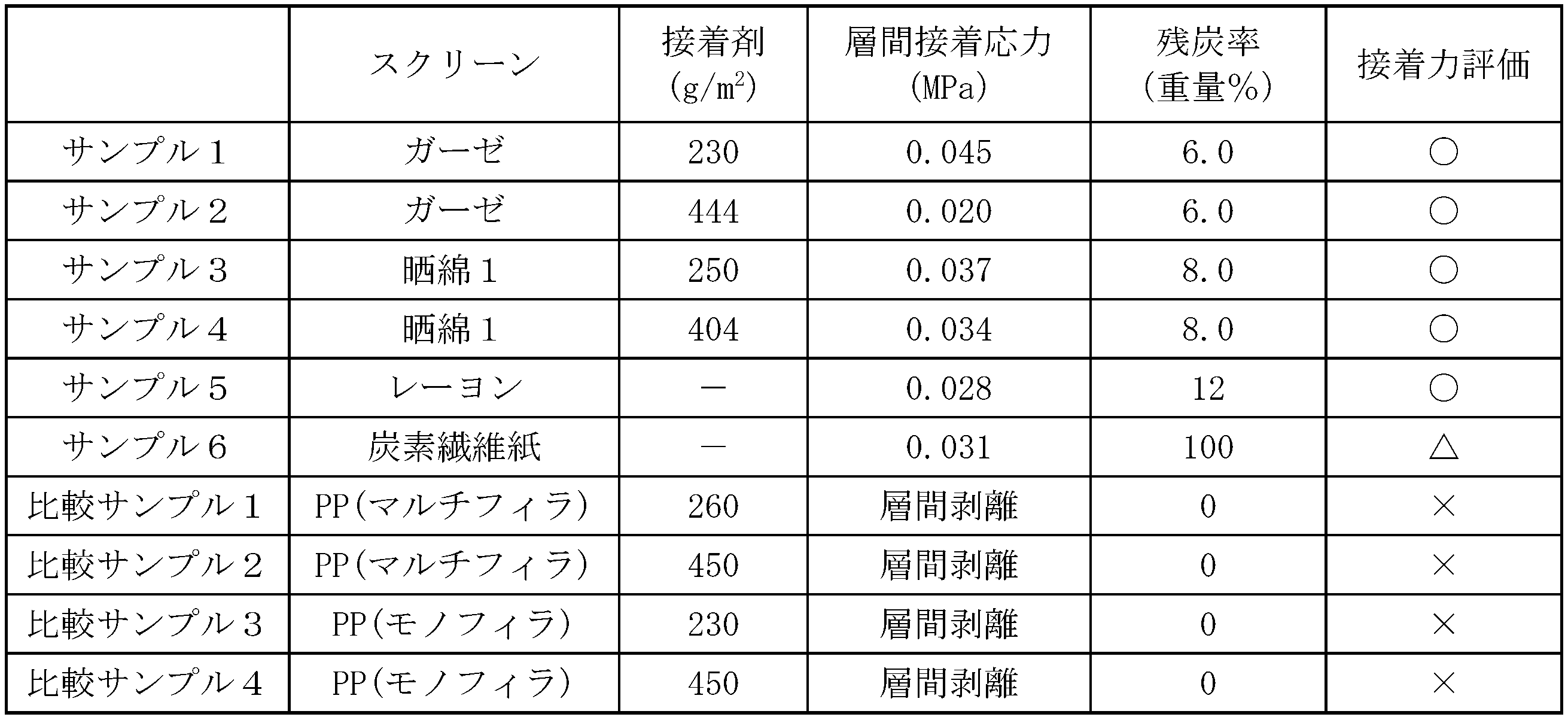
残炭率5重量%以上の有機物スクリーンと、ポリプロピレンのスクリーンを用いて、2枚の炭素繊維フェルトを、スクリーンを挟んで結合させた後に、剥離試験を行った。
2枚の炭素繊維フェルトにフェノール樹脂を含浸させ、その間に表2に記載のスクリーンと挟んだ。真空下、2000℃で1時間焼成し、L50mm×W50mm×T16mmのサンプルを調整した。測定機器はオートグラフAGS-H 5kN((株)島津製作所製)を用いた。サンプルの上下に直径100mm、厚さ3mmの樹脂版を接着させる。サンプルを測定器にセットし、樹脂版の脇をチャックする。試験片を引張速度1.0mm/minで剥離させ、その荷重(N)を測定することによって、試料の引っ張り強さ(MPa)を得た。結果を表2に示す。
それぞれのスクリーンの残炭率を、試料を不活性ガス中で強熱した後の強熱残分の炭素量を定量することにより測定した。強熱は、揮発性有機物およそ1g(この正確な重量をW1(g)とする)をるつぼに入れ、1分間に20リットルの窒素を流しながらるつぼを電気炉にて10℃/minで800℃まで昇温、その後800℃で1時間強熱した。このときの残存物を強熱残分とし、その重量をW2(g)とした。
次いで上記強熱残分について、JIS M8819に定められた方法に準拠して元素分析を行い、炭素の重量割合P1(%)を測定した。残炭率P2(%)は以下の式により算出した。

残炭率5重量%以上の有機物スクリーンと、セルロースを含まないポリプロピレンのスクリーンを用いて、スクリーンの引張試験を行った。
接着剤を表3の量で塗布したスクリーン及び接着剤を塗布しないスクリーンを調整した。オートグラフAGS-H 5kN((株)島津製作所製))を用い、JIS L1913(旧1906)の一般不織布試験方法に準拠して、引張試験を行った。結果を表3に示す。

以上、本発明を特定の態様に沿って説明したが、当業者に自明の変形や改良は本発明の範囲に含まれる。
2・・・有機物スクリーン;
3・・・巻取り機;
4・・・巻取り芯;
5・・・厚みセンサー;
Claims (8)
- 焼成炭素繊維フェルト層が、らせん状に巻回積層している中空円筒状の焼成巻回体であって、焼成炭素繊維フェルト層の積層間に残炭率5重量%以上の有機物スクリーンが焼成された焼成有機物スクリーン層を有することにより、前記積層間が結合されている焼成巻回体。
- 前記焼成有機物スクリーンが、焼成セルロース系スクリーン層である、請求項1に記載の焼成巻回体。
- 焼成巻回体の内側面及び/又は外側面に保護層を有する、請求項1に記載の焼成巻回体。
- 請求項1~3のいずれか一項に記載の焼成巻回体を含む円筒状断熱材。
- (a)炭素繊維フェルトに樹脂を含浸させる工程、
(b)残炭率5重量%以上の有機物スクリーンに引張力を付与しながら、外側の有機物スクリーンと内側の前記含浸炭素繊維フェルトとを重層して巻取芯に巻回することによって中空円筒状の焼成前巻回体を得る工程、
(c)得られた焼成前巻回体を加熱により硬化させる工程、及び
(d)硬化した焼成前巻回体を焼成する工程、
を含むことを特徴とする中空円筒状の焼成巻回体の製造方法。 - 前記有機物スクリーンが、セルロース系スクリーンである、請求項5に記載の焼成巻回体の製造方法。
- 前記有機物スクリーンの目付けが50~600g/m2である、請求項5又は6に記載の焼成巻回体の製造方法。
- 前記巻回工程(b)における有機物スクリーンが、接着剤の塗布されたものである、請求項5~7のいずれか一項に記載の焼成巻回体の製造方法。
Priority Applications (3)
| Application Number | Priority Date | Filing Date | Title |
|---|---|---|---|
| KR1020167034162A KR20170005834A (ko) | 2014-05-21 | 2015-05-21 | 원통상 단열재 및 그 제조 방법 |
| DE112015002016.0T DE112015002016T5 (de) | 2014-05-21 | 2015-05-21 | Zylindrisches Wärmeisoliermaterial und Verfahren zu dessen Herstelllung |
| CN201580027074.7A CN106414049B (zh) | 2014-05-21 | 2015-05-21 | 圆筒状绝热材料及其制造方法 |
Applications Claiming Priority (2)
| Application Number | Priority Date | Filing Date | Title |
|---|---|---|---|
| JP2014105612A JP6344972B2 (ja) | 2014-05-21 | 2014-05-21 | 円筒状断熱材及びその製造方法 |
| JP2014-105612 | 2014-05-21 |
Publications (1)
| Publication Number | Publication Date |
|---|---|
| WO2015178453A1 true WO2015178453A1 (ja) | 2015-11-26 |
Family
ID=54554114
Family Applications (1)
| Application Number | Title | Priority Date | Filing Date |
|---|---|---|---|
| PCT/JP2015/064608 Ceased WO2015178453A1 (ja) | 2014-05-21 | 2015-05-21 | 円筒状断熱材及びその製造方法 |
Country Status (5)
| Country | Link |
|---|---|
| JP (1) | JP6344972B2 (ja) |
| KR (1) | KR20170005834A (ja) |
| CN (1) | CN106414049B (ja) |
| DE (1) | DE112015002016T5 (ja) |
| WO (1) | WO2015178453A1 (ja) |
Cited By (1)
| Publication number | Priority date | Publication date | Assignee | Title |
|---|---|---|---|---|
| CN113460812A (zh) * | 2021-06-24 | 2021-10-01 | 湖北三江航天红阳机电有限公司 | 一种提高气凝胶隔热材料卷材干燥效率的工艺方法 |
Families Citing this family (4)
| Publication number | Priority date | Publication date | Assignee | Title |
|---|---|---|---|---|
| JP7288498B2 (ja) * | 2019-02-22 | 2023-06-07 | 日東電工株式会社 | 真贋判定方法および粘着シート |
| JP7709124B2 (ja) * | 2022-03-31 | 2025-07-16 | Jfeスチール株式会社 | 黒鉛含有耐火物 |
| JP7709125B2 (ja) * | 2022-03-31 | 2025-07-16 | Jfeスチール株式会社 | 黒鉛含有耐火物の製造方法 |
| CN114956848B (zh) * | 2022-04-29 | 2023-07-25 | 吉林联科特种石墨材料有限公司 | 带有石墨高效阻隔层的一体化筒形隔热材料的制备方法 |
Citations (6)
| Publication number | Priority date | Publication date | Assignee | Title |
|---|---|---|---|---|
| JPH02258245A (ja) * | 1988-08-19 | 1990-10-19 | Osaka Gas Co Ltd | 成形断熱材とその製造方法 |
| JPH03121398A (ja) * | 1989-03-23 | 1991-05-23 | Osaka Gas Co Ltd | 断熱材 |
| JPH04107398A (ja) * | 1990-08-28 | 1992-04-08 | Dainippon Ink & Chem Inc | 炭素繊維断熱材の製造方法 |
| JP2000141526A (ja) * | 1998-11-13 | 2000-05-23 | Nippon Carbon Co Ltd | 炭素繊維成形断熱材 |
| JP2006062943A (ja) * | 2004-07-27 | 2006-03-09 | Honda Motor Co Ltd | C/cコンポジット材用前躯体、及びc/cコンポジット材、並びにその製造方法 |
| JP2008196552A (ja) * | 2007-02-09 | 2008-08-28 | Nippon Carbon Co Ltd | 炭素繊維断熱材及びその製造方法 |
Family Cites Families (5)
| Publication number | Priority date | Publication date | Assignee | Title |
|---|---|---|---|---|
| US3844877A (en) * | 1969-07-30 | 1974-10-29 | Union Carbide Corp | Carbonaceous fabric laminate |
| DE2314798C3 (de) | 1973-03-24 | 1981-12-03 | Kernforschungszentrum Karlsruhe Gmbh, 7500 Karlsruhe | Doppelt eingekapselte Californium-252-oxid enthaltende Neutronenquelle kleiner Abmessung |
| US5242723A (en) * | 1988-08-19 | 1993-09-07 | Osaka Gas Company, Ltd. | Formed thermal insulator and process for preparation of same |
| US5145732A (en) * | 1989-03-01 | 1992-09-08 | Osaka Gas Company Limited | High bulk density carbon fiber felt and thermal insulator |
| CN200943780Y (zh) * | 2006-05-31 | 2007-09-05 | 杨世奉 | 耐火隔热尼龙软管 |
-
2014
- 2014-05-21 JP JP2014105612A patent/JP6344972B2/ja active Active
-
2015
- 2015-05-21 WO PCT/JP2015/064608 patent/WO2015178453A1/ja not_active Ceased
- 2015-05-21 KR KR1020167034162A patent/KR20170005834A/ko not_active Ceased
- 2015-05-21 CN CN201580027074.7A patent/CN106414049B/zh active Active
- 2015-05-21 DE DE112015002016.0T patent/DE112015002016T5/de active Pending
Patent Citations (6)
| Publication number | Priority date | Publication date | Assignee | Title |
|---|---|---|---|---|
| JPH02258245A (ja) * | 1988-08-19 | 1990-10-19 | Osaka Gas Co Ltd | 成形断熱材とその製造方法 |
| JPH03121398A (ja) * | 1989-03-23 | 1991-05-23 | Osaka Gas Co Ltd | 断熱材 |
| JPH04107398A (ja) * | 1990-08-28 | 1992-04-08 | Dainippon Ink & Chem Inc | 炭素繊維断熱材の製造方法 |
| JP2000141526A (ja) * | 1998-11-13 | 2000-05-23 | Nippon Carbon Co Ltd | 炭素繊維成形断熱材 |
| JP2006062943A (ja) * | 2004-07-27 | 2006-03-09 | Honda Motor Co Ltd | C/cコンポジット材用前躯体、及びc/cコンポジット材、並びにその製造方法 |
| JP2008196552A (ja) * | 2007-02-09 | 2008-08-28 | Nippon Carbon Co Ltd | 炭素繊維断熱材及びその製造方法 |
Cited By (1)
| Publication number | Priority date | Publication date | Assignee | Title |
|---|---|---|---|---|
| CN113460812A (zh) * | 2021-06-24 | 2021-10-01 | 湖北三江航天红阳机电有限公司 | 一种提高气凝胶隔热材料卷材干燥效率的工艺方法 |
Also Published As
| Publication number | Publication date |
|---|---|
| DE112015002016T5 (de) | 2017-02-23 |
| JP6344972B2 (ja) | 2018-06-20 |
| JP2015217669A (ja) | 2015-12-07 |
| CN106414049B (zh) | 2019-03-15 |
| CN106414049A (zh) | 2017-02-15 |
| KR20170005834A (ko) | 2017-01-16 |
Similar Documents
| Publication | Publication Date | Title |
|---|---|---|
| US20070259185A1 (en) | High-temperature-resistant composite and method of producing the composite | |
| JP6344972B2 (ja) | 円筒状断熱材及びその製造方法 | |
| JP5327412B2 (ja) | 炭素繊維強化炭素複合体およびその製造方法 | |
| US10336655B2 (en) | Process for producing shaped bodies of carbon fiber reinforced carbon | |
| JP7198215B2 (ja) | 表面層付き成形断熱材及びその製造方法 | |
| CN106478125A (zh) | 一种B4C改性C/C‑SiC刹车材料的制备方法 | |
| JP2015174807A (ja) | 炭素繊維系断熱材及びその製造方法 | |
| WO2008023777A1 (en) | Laminated molded article containing carbon fiber and method for production thereof | |
| JP2012036018A (ja) | 炭素繊維強化炭素複合材及びその製造方法 | |
| JPWO2011090151A1 (ja) | 炭素繊維積層成形体及びその製造方法 | |
| JP2012036017A (ja) | C/c複合材成形体及びその製造方法 | |
| JP2011046543A (ja) | 炭素繊維強化炭素複合材料及びその製造方法 | |
| CN102303411B (zh) | 碳纤维纸增强酚醛树脂基复合材料的制备方法 | |
| JP6703866B2 (ja) | 炭化ケイ素系複合体の製造方法 | |
| KR102078974B1 (ko) | 열전도성이 우수한 카본페이퍼의 제조방법 및 이로부터 제조된 카본페이퍼 | |
| KR101466910B1 (ko) | 산화방지 층을 포함하는 섬유강화 세라믹 복합소재 및 이의 제조 방법 | |
| JP4245725B2 (ja) | 炭素繊維強化炭素複合材料からなる高温加圧成型炉部材及びその製造方法 | |
| JP5728802B2 (ja) | 多孔質炭素電極基材およびその製造方法 | |
| JP2009280437A (ja) | 多孔質炭素シートの製造方法 | |
| US12427748B2 (en) | Composites and methods of forming composites having tailored hardness profile | |
| JP2015096464A (ja) | 多孔質炭素電極基材 | |
| JP7174094B2 (ja) | 表面層付き成形断熱材及びその製造方法 | |
| JP4185355B2 (ja) | カーボンシート及びその製造方法 | |
| CN105503226A (zh) | 一种超薄碳基复合面板及制备方法 | |
| JP2005281871A (ja) | 炭素繊維織物及びその製造方法 |
Legal Events
| Date | Code | Title | Description |
|---|---|---|---|
| 121 | Ep: the epo has been informed by wipo that ep was designated in this application |
Ref document number: 15796495 Country of ref document: EP Kind code of ref document: A1 |
|
| WWE | Wipo information: entry into national phase |
Ref document number: 112015002016 Country of ref document: DE |
|
| ENP | Entry into the national phase |
Ref document number: 20167034162 Country of ref document: KR Kind code of ref document: A |
|
| 122 | Ep: pct application non-entry in european phase |
Ref document number: 15796495 Country of ref document: EP Kind code of ref document: A1 |