WO2015178075A1 - Dispositif de commande de batterie - Google Patents
Dispositif de commande de batterie Download PDFInfo
- Publication number
- WO2015178075A1 WO2015178075A1 PCT/JP2015/057556 JP2015057556W WO2015178075A1 WO 2015178075 A1 WO2015178075 A1 WO 2015178075A1 JP 2015057556 W JP2015057556 W JP 2015057556W WO 2015178075 A1 WO2015178075 A1 WO 2015178075A1
- Authority
- WO
- WIPO (PCT)
- Prior art keywords
- battery
- secondary batteries
- unit
- assembled battery
- secondary battery
- Prior art date
Links
Images


Classifications
-
- G—PHYSICS
- G01—MEASURING; TESTING
- G01R—MEASURING ELECTRIC VARIABLES; MEASURING MAGNETIC VARIABLES
- G01R31/00—Arrangements for testing electric properties; Arrangements for locating electric faults; Arrangements for electrical testing characterised by what is being tested not provided for elsewhere
- G01R31/36—Arrangements for testing, measuring or monitoring the electrical condition of accumulators or electric batteries, e.g. capacity or state of charge [SoC]
Definitions
- Embodiments of the present invention relate to a battery control device.
- a secondary battery is used as an assembled battery in which a single battery is combined in series, in parallel, or both.
- the assembled battery is often used by being incorporated in some system (for example, for use in suppressing fluctuations in photovoltaic power generation or for in-vehicle use such as EV and HEV).
- the charging ends when the voltage of each secondary battery (also referred to as a cell) constituting the assembled battery reaches the upper limit value.
- the voltage of each secondary battery which comprises an assembled battery reaches
- the battery control device of the embodiment includes a storage unit, a specifying unit, and an output unit.
- the specifying unit can estimate the deterioration of each of the plurality of secondary batteries based on the state change accompanying the time transition of each of the plurality of secondary batteries constituting the assembled battery stored in the storage unit.
- a characteristic value is calculated, and a secondary battery that is more than a predetermined threshold is identified from an average value of characteristic values that can be estimated to deteriorate among a plurality of secondary batteries.
- the output unit outputs that the secondary battery specified by the specifying unit has deteriorated.
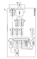
- FIG. 1 is a block diagram illustrating a configuration of the battery control device according to the first embodiment.
- FIG. 2 is a diagram illustrating configurations of the assembled battery, the current detection device, the voltage detector, and the temperature detector according to the first embodiment.
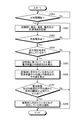
- FIG. 3 is a flowchart showing the procedure of a process for detecting deterioration of the secondary battery constituting the assembled battery in the battery control device of the first embodiment.
- FIG. 4 is a block diagram showing the configuration of the battery control device of the second embodiment.
- FIG. 5 is a block diagram showing the configuration of the battery control device of the third embodiment.
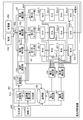
- FIG. 6 is a block diagram showing the configuration of the battery control device of the fourth embodiment.
- FIG. 1 is a block diagram showing a configuration of the battery control device 100 of the present embodiment.
- the battery control device 100 includes an assembled battery 101, a current detector 102, a current measurement unit 103, a voltage detector 104, a voltage measurement unit 105, a temperature detector 106, and a temperature.
- a measurement unit 107, a timer IC 108, a storage unit 109, a specifying unit 110, an output unit 112, and a communication I / F 111 are provided.
- the assembled battery 101 has a configuration in which a plurality of secondary batteries are connected in series, parallel, or a combination of series and parallel.
- the assembled battery 101 supplies DC power to the load 150 connected via the current detector 102.
- the load 150 only needs to use supplied DC power, and may be, for example, a drive source that is driven by DC power.
- the current detector 102 detects a current flowing for each secondary battery, and outputs a signal representing the current to the current measuring unit 103.
- the current measuring unit 103 converts a signal (for example, an analog signal) output from the current detector 102 into a current value (digital value) that flows for each secondary battery constituting the assembled battery 101, and stores the current value. Output to the unit 109.
- the voltage detector 104 is provided for each secondary battery constituting the assembled battery 101, detects the voltage of the secondary battery, and outputs a signal indicating the voltage.
- the voltage measuring unit 105 converts a signal (for example, an analog signal) output from each of the current detectors 102 into a voltage value (digital value) for each secondary battery that constitutes the assembled battery 101, for each secondary battery. Are output to the storage unit 109.
- the temperature detector 106 is provided for each secondary battery constituting the assembled battery 101, detects the temperature of the secondary battery, and outputs a signal indicating the temperature.
- the temperature measurement unit 107 converts a signal (for example, an analog signal) output from each of the temperature detectors 106 into a temperature (digital value) for each secondary battery that constitutes the assembled battery 101, and The temperature is output to the storage unit 109.
- FIG. 2 is a diagram showing the configuration of the assembled battery 101, the current detector 102, the voltage detector 104, and the temperature detector 106 of the present embodiment.
- a plurality of secondary batteries 201 to 208 also called cells, are connected in series, parallel, or a combination of series and parallel.
- an arm in which secondary batteries 201 to 204 are connected in series and an arm in which secondary batteries 205 to 208 are connected in series are parallel. It is an example connected to.
- this embodiment shows the structural example of the assembled battery 101, Comprising: It does not restrict
- the current detector 102 is provided for each arm constituting the assembled battery 101, and a signal indicating a current value flowing through the arm is used as a current of all secondary batteries connected to the arm. Output as a signal indicating the value.
- the temperature detector 106 is provided for each of the secondary batteries 205 to 208, and outputs a signal indicating the temperature measured for each of the secondary batteries 205 to 208 to the temperature measuring unit 107.
- the voltage detector 104 is provided for each of the secondary batteries 205 to 208, and outputs a signal indicating the voltage between the terminals of the secondary batteries 205 to 208 to the voltage measuring unit 105.
- a temperature detector 106 and a voltage detector 104 are provided for each of the secondary batteries 201 to 204. As described above, the temperature detector 106 and the voltage detector 104 are provided for each secondary battery constituting the assembled battery 101. In addition, this embodiment has shown as an example about the detection method of temperature and a voltage, You may use another detection method.
- a signal indicating the temperature of the secondary battery is input to the temperature measuring unit 107, and for all the secondary batteries constituting the assembled battery 101, the secondary battery A signal indicating the voltage of the battery is input to the voltage measuring unit 105.
- the timer IC 108 is an IC having a function of notifying the current time or the elapsed time from the start of measurement, and outputs the current time or the elapsed time to the storage unit 109.
- the battery control device 100 considers charge / discharge stop when the current measured by the current measuring unit 103 is within a certain range (for example, within ⁇ 0.05 A), and is out of range (for example, ⁇ 0.5 A).
- a certain range for example, within ⁇ 0.05 A
- ⁇ 0.5 A for example, ⁇ 0.5 A
- the storage unit 109 needs to be a nonvolatile memory (for example, an EEPROM). Absent.
- the storage unit 109 stores a change in state associated with time transition of each of the plurality of secondary batteries constituting the assembled battery 101.
- the current value, temperature, and voltage value for each secondary battery are stored in association with the time output from the timer IC 108.
- the current change, the temperature change, and the voltage change are stored in the storage unit 109 as the state change at the time of charging.
- this embodiment uses the voltage change during charge of the assembled battery 101 for the deterioration estimation of a secondary battery.
- the specifying unit 110 includes a deterioration estimation condition determination unit 121, a deterioration calculation unit 122, and a cell diagnosis unit 123, and each of a plurality of secondary batteries constituting the assembled battery 101 stored in the storage unit 109 is stored in the storage unit 109. Based on the state change accompanying the time transition, for each of the plurality of secondary batteries, a characteristic value that can be estimated for deterioration is calculated, and from the average value of the characteristic values that can be estimated for deterioration in the plurality of secondary batteries. A secondary battery that is more than a predetermined threshold is specified. In the present embodiment, the battery capacity and the internal resistance are specified as the characteristic values that can be estimated to be deteriorated, but any parameters may be used as long as the characteristics can estimate the deterioration of the secondary battery.
- the deterioration estimation condition determination unit 121 determines whether or not a condition for estimating the deterioration of the secondary battery is satisfied based on the information stored in the storage unit 109. For example, when the temperature measured from each secondary battery is extremely high, or when the current value flowing through the secondary battery is not stable, it may not be in an appropriate state for estimating the deterioration of the secondary battery. is there. Therefore, the deterioration estimation condition determination unit 121 calculates the deterioration when the temperature measured from each of the secondary batteries is an appropriate temperature and the current value flowing through the secondary battery is stable, assuming that the condition is satisfied. An estimation request for deterioration of the secondary battery is made to the unit 122.
- the deterioration calculating unit 122 calculates the battery capacity and the internal resistance based on the voltage change during charging derived from the voltage value stored in the storage unit 109.
- the internal resistance increases and the battery capacity decreases. For this reason, the amount of change in the charging voltage value with time transition of the rechargeable battery varies with deterioration. Therefore, the current characteristics of the secondary battery can be recognized by measuring the amount of change in the charging voltage value with time transition of the secondary battery.
- Specific battery capacity and internal resistance calculation methods include, for example, a method described in Japanese Patent Application Laid-Open No. 2011-75461. However, the method is not limited to this method, and other methods may be used.
- this embodiment demonstrates the example which calculates a battery capacity
- the cell diagnosis unit 123 calculates an average value of the battery capacity and the internal resistance in all the secondary batteries constituting the assembled battery 101. Thereafter, the cell diagnosis unit 123 identifies secondary batteries whose battery capacity and internal resistance are separated by a predetermined threshold or more compared to the calculated average values of battery capacity and internal resistance. For example, the cell diagnosis unit 123 may use a secondary battery (cell) whose battery capacity is smaller than a first predetermined threshold value compared to the average value or a secondary battery whose internal resistance is larger than a second predetermined threshold value than the average value. The battery (cell) is identified as having deteriorated. Note that the first predetermined threshold value and the second predetermined threshold value are values set according to the embodiment, such as actual battery capacity and internal resistance, and the description thereof is omitted.
- the communication I / F 111 is an interface connected to a network in order for the battery control device 100 to transmit / receive information to / from other devices.
- the communication I / F 111 according to the present embodiment enables transmission / reception of information to / from a terminal used by a user via a network.
- the output unit 112 outputs that the secondary battery (cell) has deteriorated to the terminal used by the user via the communication I / F 111 in accordance with the diagnosis result of the cell diagnosis unit 123. At that time, information for specifying the position of the secondary battery in which the deterioration has occurred is also output. Thereby, the user can recognize which secondary battery among the assembled batteries 101 has deteriorated.
- this embodiment demonstrated the example output to the terminal etc. which were connected via the network, the output destination is not restrict
- the storage unit 109 holds circuit information indicating the electric circuit in the assembled battery 101, and the output unit 112 performs communication. You may notify via the I / F 111 which position the secondary battery has deteriorated according to the circuit information.
- FIG. 3 is a flowchart showing a procedure of the above-described process in the battery control device 100 of the present embodiment.
- the current measurement unit 103 determines whether charging / discharging has been started from the charging / discharging stop state from the current flowing through the secondary battery constituting the assembled battery 101 (step S301). When it determines with charging / discharging not being started (step S301: No), the process of step S301 is repeated again.
- the storage unit 109 calculates the current value, voltage value, and temperature for each secondary battery constituting the assembled battery 101. The time is stored in association with the time (step S302).
- the current measuring unit 103 determines whether charging / discharging has stopped from the current flowing through the secondary battery constituting the assembled battery 101 (step S303). If it is determined that charging / discharging has not stopped (step S303: No), the storage of the current value, voltage value, and temperature for each secondary battery constituting the assembled battery 101 in correspondence with the time is continued (step). S302).
- the degradation estimation condition determination unit 121 determines that the secondary battery is It is determined whether or not a deterioration determination condition capable of determining deterioration is satisfied (step S304).
- the judgment targets are the voltage at the start and end of charging, the temperature at the start and end of charging, and the current during charging.
- the deterioration estimation condition determining unit 121 determines that the deterioration determination condition is satisfied (step S304: Yes)
- the deterioration calculating unit 122 is based on the information stored in the storage unit 109.
- the battery capacity and the internal resistance are calculated for each secondary battery (cell) for all the secondary batteries (cells) included in (Step S305).
- the cell diagnosis unit 123 calculates the average value of the battery capacity and the average value of the internal resistance in all the secondary batteries constituting the assembled battery 101 (step S306). Then, the cell diagnosis unit 123 determines whether there is a secondary battery (cell) whose battery capacity and internal resistance are separated from the average value by a predetermined threshold or more (step S307). When it is determined that there is no secondary battery (cell) separated from the average value by a predetermined threshold or more (S307: No), the process ends.
- the cell diagnosis unit 123 determines that there is a secondary battery (cell) whose battery capacity and internal resistance are separated from the average value by a predetermined threshold or more (S307: Yes), it is included in the assembled battery 101.
- the user's terminal or the like is notified that the secondary battery (cell) has deteriorated (step S308). At that time, information that can specify the position of the deteriorated secondary battery is also notified.
- the battery capacity varies due to the use of the assembled battery 101.
- the battery capacity becomes smaller than the predetermined threshold value from the average value. Can be recognized by the user. In that case, you may notify a user of the secondary battery in which the said degradation has arisen as a cell which needs replacement
- the battery capacity and the internal resistance are calculated as the characteristic values capable of estimating the deterioration of the secondary battery.
- the characteristic value that can be used to estimate the deterioration of the secondary battery is not limited to the battery capacity and the internal resistance. Therefore, in the present embodiment, an example will be described in which the voltage change width during a predetermined time is used as a characteristic value that can be used to estimate the deterioration of the secondary battery.
- the deterioration of the secondary battery is determined using the change width of the voltage during a certain time from the start of charging or discharging as a characteristic value that can be used to estimate the deterioration of the secondary battery.
- FIG. 4 is a block diagram showing a configuration of the battery control device 400 of the present embodiment. As shown in FIG. 4, the battery control device 400 is different from the battery control device 100 of the first embodiment in that a specifying unit 401 is provided instead of the specifying unit 110.
- the timer IC 108 counts for a certain period of time as described above after charging starts. Note that an appropriate value is set for the fixed time according to the embodiment, and for example, 5 seconds may be considered.
- the storage unit 109 of the present embodiment stores the voltage value of each secondary battery that constitutes the assembled battery 101 until the timer IC 108 finishes counting for a certain period of time (until a certain period of time has elapsed since the start of charging). deep.
- the specifying unit 401 includes a voltage difference calculation unit 411 and a cell diagnosis unit 412.
- the change width is more than a predetermined threshold from the average value of the change width of the voltage measured during a certain time after the start of charging. Identify the secondary battery.
- the voltage difference calculation unit 411 calculates the maximum voltage value within a certain time from the start of charging for each secondary battery constituting the assembled battery 101 from the voltage value associated with the time stored in the storage unit 109. A change width of the voltage which is a difference between the minimum voltage value is calculated.
- the cell diagnosis unit 412 calculates the average value of the change width of the voltage value within a certain time after the start of charging in all the secondary batteries constituting the assembled battery 101. Thereafter, the cell diagnosis unit 412 identifies secondary batteries whose voltage value change width is more than a predetermined threshold compared to the calculated average value of voltage value change widths.
- the predetermined threshold is a value set according to the embodiment, and the description thereof is omitted.
- the cell diagnosis unit 412 does not perform diagnosis when the current state changes, for example, charging is completed before a certain time has elapsed since the start of charging.
- the output unit 112 outputs information indicating that the secondary battery (cell) has deteriorated to the terminal or the like used by the user according to the diagnosis result of the cell diagnosis unit 412 via the communication I / F 111.
- the same effect as in the first embodiment can be obtained by specifying the deterioration of the secondary battery based on the change width of the voltage value.
- the characteristic value that can be used to estimate the deterioration of the secondary battery is not limited to the battery capacity, the internal resistance, and the voltage change width. Therefore, in the present embodiment, an example will be described in which the change width of the temperature during a certain time is used as a characteristic value that can be used to estimate the deterioration of the secondary battery.
- the temperature change width changes as the internal resistance increases. Therefore, in the present embodiment, an example will be described in which the deterioration of the secondary battery is determined using the change width of the temperature during a certain time from the start of charging or discharging as a characteristic value that can be used to estimate the deterioration of the secondary battery. .
- FIG. 5 is a block diagram showing a configuration of the battery control device 500 of the present embodiment. As shown in FIG. 5, the battery control device 500 is different from the battery control device 400 of the second embodiment in that a specifying unit 501 is provided instead of the specifying unit 401.
- the storage unit 109 stores the temperature of each secondary battery that constitutes the assembled battery 101 until the timer IC 108 finishes counting for a certain period of time (until a certain period of time has elapsed since the start of charging). .
- the specifying unit 501 includes a temperature difference calculation unit 511 and a cell diagnosis unit 512, and a change width is a predetermined threshold value based on an average value of temperature change widths measured during a predetermined time after the start of charging or discharging. Identify secondary batteries that are separated from each other.
- the temperature difference calculation unit 511 calculates the maximum temperature within a predetermined time from the start of charging or discharging for each secondary battery constituting the assembled battery 101 from the temperature associated with the time stored in the storage unit 109.
- the change width of the temperature which is the difference from the minimum temperature, is calculated.
- the cell diagnosis unit 512 calculates the average value of the change width of the temperature within a certain time after the start of charging or discharging in all the secondary batteries constituting the assembled battery 101. After that, the cell diagnosis unit 512 identifies secondary batteries whose temperature change width is more than a predetermined threshold compared to the average value of the calculated temperature change width.
- the predetermined threshold is a value set according to the embodiment, and the description thereof is omitted.
- the output unit 112 outputs information indicating that the secondary battery (cell) has deteriorated to the terminal or the like used by the user according to the diagnosis result of the cell diagnosis unit 412 via the communication I / F 111.
- the use of the arm including the secondary battery in the assembled battery 101 that has deteriorated is stopped.
- the time during which the assembled battery 101 can supply power is shortened, but stable power supply is possible.
- FIG. 6 is a block diagram showing a configuration of the battery control device 600 of the present embodiment.
- the battery control device 600 is different from the battery control device 500 of the third embodiment in that a switch control unit 601 and a switching unit 602 are added, and the assembled battery 101 is changed to an assembled battery 603. It is assumed that
- the switching unit 602 performs control to switch between the load 150 and the rechargeable battery 650.
- the assembled battery 603 of this embodiment includes an arm in which secondary batteries (cells) 621_1 to 621_4 are connected in series, an arm in which secondary batteries (cells) 622_1 to 622_4 are connected in series, and a secondary battery (cell). ) An example in which the arms 623_1 to 623_4 connected in series are connected in parallel.
- this embodiment shows the structural example of the assembled battery 603, Comprising: Connection form, such as the number of connection of a cell and parallel and series, is not restrict
- the first switch unit 611 is provided on the arm to which the secondary batteries (cells) 621_1 to 621_4 are connected, and the first battery is connected to the arm to which the secondary batteries (cells) 622_1 to 622_4 are connected.
- the second switch unit 612 is provided, and the third switch unit 613 is provided on the arm to which the secondary batteries (cells) 623_1 to 623_4 are connected.
- the switch part is provided for every arm.
- the switch control unit 601 outputs a switching signal (use OFF signal) to the switch unit connected to the arm including the secondary battery determined to have deteriorated by the cell diagnosis unit 512, and the arm (column) is output. Control to degenerate.
- the switch control unit 601 controls the second switch unit 612 to control the secondary battery ( Cell)
- the arm including 622_2 is controlled to stop use.
- the storage unit 109 stores the correspondence relationship between the cell and the switch unit to stop the use of the cell, and the switch control unit 601 controls the switch units 611 to 613 according to the correspondence relationship. You may do it.
- a user can recognize a secondary battery that has deteriorated greatly as a result of using the secondary battery constituting the assembled battery. As a result, for example, it is possible to replace the assembled battery and the secondary battery constituting the assembled battery, stop the use of the deteriorated secondary battery, etc. Power supply can be realized.
Landscapes
- Physics & Mathematics (AREA)
- General Physics & Mathematics (AREA)
- Charge And Discharge Circuits For Batteries Or The Like (AREA)
- Secondary Cells (AREA)
Abstract
Un dispositif de commande de batterie selon un mode de réalisation de la présente invention est pourvu d'une unité de stockage, d'une unité de spécification, et d'une unité de sortie. L'unité de stockage stocke les modifications d'état qui se produisent dans le temps dans une pluralité de batteries rechargeables qui forment un bloc-batterie. L'unité de spécification calcule des valeurs caractéristiques au moyen desquelles il est possible d'estimer la dégradation pour chaque batterie de la pluralité de batteries rechargeables, un tel calcul étant effectué sur la base des modifications d'état qui sont stockées dans l'unité de stockage et qui se produisent dans le temps dans la pluralité de batteries rechargeables qui forment le bloc-batterie. En outre, l'unité de spécification spécifie, parmi la pluralité de batteries rechargeables, une batterie rechargeable ayant une valeur caractéristique qui s'écarte, d'au moins un seuil prescrit, d'une valeur moyenne des valeurs caractéristiques au moyen desquelles il est possible d'estimer la dégradation. L'unité de sortie effectue une sortie indiquant que la dégradation s'est produite dans la batterie rechargeable spécifiée par l'unité de spécification.
Applications Claiming Priority (2)
| Application Number | Priority Date | Filing Date | Title |
|---|---|---|---|
| JP2014106411A JP2017125680A (ja) | 2014-05-22 | 2014-05-22 | 電池制御装置 |
| JP2014-106411 | 2014-05-22 |
Publications (1)
| Publication Number | Publication Date |
|---|---|
| WO2015178075A1 true WO2015178075A1 (fr) | 2015-11-26 |
Family
ID=54553752
Family Applications (1)
| Application Number | Title | Priority Date | Filing Date |
|---|---|---|---|
| PCT/JP2015/057556 WO2015178075A1 (fr) | 2014-05-22 | 2015-03-13 | Dispositif de commande de batterie |
Country Status (2)
| Country | Link |
|---|---|
| JP (1) | JP2017125680A (fr) |
| WO (1) | WO2015178075A1 (fr) |
Cited By (2)
| Publication number | Priority date | Publication date | Assignee | Title |
|---|---|---|---|---|
| JP2019045501A (ja) * | 2017-09-05 | 2019-03-22 | 株式会社デンソー | 信号検出装置 |
| CN114002517A (zh) * | 2020-07-28 | 2022-02-01 | 比亚迪股份有限公司 | 器件诊断方法、平台、系统及可读存储介质 |
Families Citing this family (5)
| Publication number | Priority date | Publication date | Assignee | Title |
|---|---|---|---|---|
| JP7039963B2 (ja) * | 2017-11-28 | 2022-03-23 | 株式会社デンソー | 電池制御システム |
| JP7275490B2 (ja) * | 2018-07-31 | 2023-05-18 | 株式会社Gsユアサ | 容量推定システム、容量推定方法、及び通信デバイス |
| US11536774B2 (en) | 2018-06-14 | 2022-12-27 | Gs Yuasa International Ltd. | Communication device, information processing system, information processing method, and computer program |
| JP7044044B2 (ja) * | 2018-12-07 | 2022-03-30 | トヨタ自動車株式会社 | 二次電池の劣化度推定装置および二次電池の劣化度推定方法 |
| WO2022162887A1 (fr) * | 2021-01-29 | 2022-08-04 | 株式会社日立ハイテク | Dispositif de diagnostic de batterie, procédé de diagnostic de batterie et programme de diagnostic de batterie |
Citations (5)
| Publication number | Priority date | Publication date | Assignee | Title |
|---|---|---|---|---|
| JP2011257372A (ja) * | 2010-06-08 | 2011-12-22 | Hyundai Motor Company Co Ltd | 車両用バッテリーのセル劣化診断方法 |
| JP2012125121A (ja) * | 2010-12-10 | 2012-06-28 | Nippon Telegr & Teleph Corp <Ntt> | 充電システム及び蓄電池劣化判定方法 |
| WO2012098794A1 (fr) * | 2011-01-18 | 2012-07-26 | 日産自動車株式会社 | Dispositif de commande de batteries |
| JP2012181037A (ja) * | 2011-02-28 | 2012-09-20 | Mitsubishi Heavy Ind Ltd | 劣化推定装置、劣化推定方法、及びプログラム |
| JP2013246088A (ja) * | 2012-05-28 | 2013-12-09 | Toyota Industries Corp | 電池の内部抵抗推定方法及びその装置 |
-
2014
- 2014-05-22 JP JP2014106411A patent/JP2017125680A/ja active Pending
-
2015
- 2015-03-13 WO PCT/JP2015/057556 patent/WO2015178075A1/fr active Application Filing
Patent Citations (5)
| Publication number | Priority date | Publication date | Assignee | Title |
|---|---|---|---|---|
| JP2011257372A (ja) * | 2010-06-08 | 2011-12-22 | Hyundai Motor Company Co Ltd | 車両用バッテリーのセル劣化診断方法 |
| JP2012125121A (ja) * | 2010-12-10 | 2012-06-28 | Nippon Telegr & Teleph Corp <Ntt> | 充電システム及び蓄電池劣化判定方法 |
| WO2012098794A1 (fr) * | 2011-01-18 | 2012-07-26 | 日産自動車株式会社 | Dispositif de commande de batteries |
| JP2012181037A (ja) * | 2011-02-28 | 2012-09-20 | Mitsubishi Heavy Ind Ltd | 劣化推定装置、劣化推定方法、及びプログラム |
| JP2013246088A (ja) * | 2012-05-28 | 2013-12-09 | Toyota Industries Corp | 電池の内部抵抗推定方法及びその装置 |
Cited By (3)
| Publication number | Priority date | Publication date | Assignee | Title |
|---|---|---|---|---|
| JP2019045501A (ja) * | 2017-09-05 | 2019-03-22 | 株式会社デンソー | 信号検出装置 |
| JP7103084B2 (ja) | 2017-09-05 | 2022-07-20 | 株式会社デンソー | 信号検出装置 |
| CN114002517A (zh) * | 2020-07-28 | 2022-02-01 | 比亚迪股份有限公司 | 器件诊断方法、平台、系统及可读存储介质 |
Also Published As
| Publication number | Publication date |
|---|---|
| JP2017125680A (ja) | 2017-07-20 |
Similar Documents
| Publication | Publication Date | Title |
|---|---|---|
| WO2015178075A1 (fr) | Dispositif de commande de batterie | |
| JP6056730B2 (ja) | 蓄電システム | |
| US9444267B2 (en) | Cell voltage equalizer for multi-cell battery pack which determines the waiting time between equalization operations based on the voltage difference and the state of charge level | |
| US9438059B2 (en) | Battery control apparatus and battery control method | |
| JP5621818B2 (ja) | 蓄電システムおよび均等化方法 | |
| CN106662621B (zh) | 电池状态检测装置、二次电池系统、程序产品和电池状态检测方法 | |
| CN106662620B (zh) | 电池状态探测装置、二次电池系统、存储介质、电池状态探测方法 | |
| JPWO2014132403A1 (ja) | 二次電池劣化度判定装置 | |
| JP5910889B2 (ja) | 蓄電システム | |
| JP2015136268A (ja) | 組電池の均等化装置及び方法 | |
| JP2016014588A (ja) | バッテリ管理装置 | |
| WO2012132160A1 (fr) | Dispositif pour mesurer une dégradation, unité d'accumulateurs rechargeables, procédé pour mesurer une dégradation, et programme associé | |
| JP2010032412A (ja) | 車両用の電源装置 | |
| US20160028255A1 (en) | Secondary-battery charging system and method and battery pack | |
| WO2013008409A1 (fr) | Procédé pour fabriquer un ensemble de batteries et ensemble de batteries | |
| JP2018125965A (ja) | 蓄電装置および蓄電制御方法 | |
| JP2013121242A (ja) | Soc推定装置及び電池パック | |
| JP5314626B2 (ja) | 電源システム、放電制御方法および放電制御プログラム | |
| JP2009232659A (ja) | バッテリの充放電制御方法及び充放電制御装置 | |
| JP2015195653A (ja) | 電池システム、充放電制御プログラム、充放電制御方法 | |
| WO2015133401A1 (fr) | Unité de commande, système de batterie de stockage, procédé d'équilibrage de cellules de batterie, et programme | |
| JP2014115127A (ja) | 満充電容量推定装置及び方法 | |
| JP2014109535A (ja) | 内部抵抗推定装置、充電装置、放電装置、内部抵抗推定方法 | |
| JP5999409B2 (ja) | 状態推定装置及び状態推定方法 | |
| JP7167581B2 (ja) | 二次電池装置 |
Legal Events
| Date | Code | Title | Description |
|---|---|---|---|
| 121 | Ep: the epo has been informed by wipo that ep was designated in this application |
Ref document number: 15796185 Country of ref document: EP Kind code of ref document: A1 |
|
| NENP | Non-entry into the national phase |
Ref country code: DE |
|
| 122 | Ep: pct application non-entry in european phase |
Ref document number: 15796185 Country of ref document: EP Kind code of ref document: A1 |
|
| NENP | Non-entry into the national phase |
Ref country code: JP |