WO2015178044A1 - 自走式電子機器 - Google Patents
自走式電子機器 Download PDFInfo
- Publication number
- WO2015178044A1 WO2015178044A1 PCT/JP2015/051374 JP2015051374W WO2015178044A1 WO 2015178044 A1 WO2015178044 A1 WO 2015178044A1 JP 2015051374 W JP2015051374 W JP 2015051374W WO 2015178044 A1 WO2015178044 A1 WO 2015178044A1
- Authority
- WO
- WIPO (PCT)
- Prior art keywords
- self
- distance
- target object
- electronic device
- propelled electronic
- Prior art date
- Legal status (The legal status is an assumption and is not a legal conclusion. Google has not performed a legal analysis and makes no representation as to the accuracy of the status listed.)
- Ceased
Links
Images







Classifications
-
- A—HUMAN NECESSITIES
- A47—FURNITURE; DOMESTIC ARTICLES OR APPLIANCES; COFFEE MILLS; SPICE MILLS; SUCTION CLEANERS IN GENERAL
- A47L—DOMESTIC WASHING OR CLEANING; SUCTION CLEANERS IN GENERAL
- A47L9/00—Details or accessories of suction cleaners, e.g. mechanical means for controlling the suction or for effecting pulsating action; Storing devices specially adapted to suction cleaners or parts thereof; Carrying-vehicles specially adapted for suction cleaners
- A47L9/28—Installation of the electric equipment, e.g. adaptation or attachment to the suction cleaner; Controlling suction cleaners by electric means
-
- G—PHYSICS
- G05—CONTROLLING; REGULATING
- G05D—SYSTEMS FOR CONTROLLING OR REGULATING NON-ELECTRIC VARIABLES
- G05D1/00—Control of position, course, altitude or attitude of land, water, air or space vehicles, e.g. using automatic pilots
- G05D1/02—Control of position or course in two dimensions
Definitions
- the present invention relates to a self-propelled electronic device, and more particularly to a self-propelled electronic device having a function of automatically returning to a charging stand.
- the robot cleaner is equipped with a rechargeable battery, and when the remaining capacity of the rechargeable battery falls below a predetermined value, the robot cleaner returns to a charging stand fixedly arranged at a predetermined position in the room and connects the rechargeable battery to the charging stand. Some have the function of charging.
- the charging stand As a method of returning to the charging stand, for example, when an infrared signal is sent from the charging stand toward a predetermined area and the infrared signal is received by the infrared receiving unit provided in the robot cleaner, the charging stand is used. Detects the direction of the vehicle and travels toward the charging stand.
- the infrared signal is a radio signal having a certain directionality
- the robot cleaner was in a position where it could not receive such infrared signals, it had to travel to a position where it could receive infrared signals by running along the wall surface (edge running) or running randomly. .
- the present invention has been made in consideration of the above circumstances, and when charging is necessary, it minimizes unnecessary movement until returning to the charging stand and returns to the charging stand. It is an object of the present invention to provide a self-propelled electronic device that can shorten the time required for the above.
- the present invention is a self-propelled electronic device that automatically travels toward the position of a target object, and is transmitted from the target object, a travel control unit that controls the rotation of wheels to perform linear travel and rotational operation.
- a signal communication unit that receives the received radio signal, a distance measurement unit that measures a distance to the target object based on the received radio signal, and a control unit, and the distance measurement unit during automatic traveling
- the control unit performs a predetermined rotation operation at the current position.
- a self-propelled electronic device that is moved to a predetermined vicinity region of the target object by repeatedly performing a linear travel and a rotating operation in a direction approaching the target object after being performed. What to do A.
- a self-propelled electronic device that automatically travels toward the position of the target object, the travel control unit controlling the rotation of the wheels to perform linear travel and rotational operation, and the wireless transmitted from the target object
- a signal communication unit that receives a signal; a distance measurement unit that measures a distance to the target object based on the received radio signal; and a latest current position measured by the distance measurement unit during automatic traveling
- a distance determination unit that determines a magnitude relationship by comparing the measurement distance at the minimum measurement distance among a plurality of past measurement distances during automatic traveling, and a control unit, the distance determination unit, When it is determined that the measurement distance at the current position is larger than the minimum measurement distance, the control unit performs a predetermined rotation operation at the current position and then approaches the target object.
- Straight running and rotating motion By performing return Ri, there is provided a self-propelled electronic device and moving to a predetermined region near the target object.
- the wireless signal is a BLE signal defined by a Bluetooth low energy standard that can communicate with ultra-low power in one of the Bluetooth extended specifications, and is based on the reception intensity of the BLE signal received by the signal communication unit.
- the distance measuring unit measures a distance to the target object. According to this, since the distance to the target object is measured based on the received BLE signal, the self-propelled electronic device receives the BLE signal regardless of whether there is an obstacle in the traveling direction. As long as the distance is within the range, the linear distance between the self-propelled electronic device and the target object can be calculated.
- the control unit when it is determined that the self-propelled electronic device is moving in a direction away from the target object, the control unit performs a rotation operation of 180 degrees or a rotation operation of 90 degrees to perform linear traveling
- the vehicle is moved to a predetermined vicinity area of the target object by performing traveling that combines a rotation operation of 180 degrees and a rotation operation of 90 degrees. According to this, since traveling is performed by combining straight traveling, 180-degree rotational motion, and 90-degree rotational motion, the target object can be brought closer by performing traveling along the wall or random traveling. Compared to the above, it is possible to reduce useless travel and to shorten the time required to move to a region near the target object.
- the control unit when it is determined that the self-propelled electronic device is moving in a direction away from the target object, the control unit performs a 90-degree rotation operation in a certain direction at the determined current position.
- the vehicle is moved to a predetermined vicinity region of the target object by performing a combination of a straight traveling and a rotation operation of 90 degrees in the same direction as the fixed direction. According to this, since traveling is performed by combining linear traveling and 90-degree rotational movement in a certain direction, compared to the case where the target object is brought closer by performing traveling along the wall or random traveling, Unnecessary travel can be reduced, and the time required to move to a region near the target object can be shortened.
- the angle of the rotation operation may be any randomly generated angle or a preset fixed value.
- the target object may be a mobile object, and the self-propelled electronic device may follow the mobile object.
- the self-propelled electronic device is a self-propelled cleaner having a rechargeable battery and a cleaning function
- the target object is a charging stand
- the control unit is a rechargeable battery of the self-propelled cleaner.
- the distance from the self-propelled electronic device to the target object is measured, and the linear travel and the rotation operation are repeatedly performed in the direction approaching the target object based on the measured distance. It is possible to reduce unnecessary travel of the electronic device, and to shorten the time until the self-propelled electronic device moves to a predetermined vicinity region of the target object.
- the self-propelled electronic device of the present invention is an electronic device that automatically travels toward the position of the target object.
- the structure of the "self-propelled cleaner" provided with the rechargeable battery and the cleaning function is demonstrated as one Example of the self-propelled electronic device of this invention.
- the target object is a charging stand.
- the present invention may be any electronic device that includes at least a rechargeable battery, performs automatic traveling control, and has a function of moving to a region near the target object by automatic traveling, and is limited to a self-propelled cleaner. It is not a thing.
- the target object is not limited to the charging stand.
- a self-propelled air cleaner that sucks air and exhausts purified air
- a self-propelled ion generator that generates ions
- a self-propelled robot that performs a function requested by the user.
- the target object includes any tangible object having a signal communication unit described later.
- FIG. 1 is a block diagram showing the construction of an embodiment of the self-propelled cleaner according to the present invention.
- a self-propelled cleaner hereinafter also referred to as a vacuum cleaner or a cleaner
- a control unit 11 mainly includes a control unit 11, a rechargeable battery 12, a remaining battery level detection unit 13, a signal communication unit 14, and an ultrasonic sensor 15.
- Distance measuring unit 16 distance determining unit 17, infrared receiving unit 18, traveling control unit 21, wheel 22, intake port 31, exhaust port 32, dust collecting unit 33, failure detection unit 34, input unit 35, storage unit 41,
- a charging stand connection unit 51 is provided.
- the charging stand 100 is fixedly installed at a predetermined position such as a room to be cleaned.
- the self-propelled cleaner 1 is supplied with electric power from the charging stand in contact with the charging stand, and the rechargeable battery 12 of the self-propelled cleaner 1.
- the self-propelled cleaner 1 performs a cleaning function while automatically traveling away from the charging stand 100.
- the self-propelled cleaner 1 of the present invention cleans the floor surface by sucking air containing dust on the floor surface and exhausting the air from which dust has been removed while traveling on the floor surface of the place where it is installed. It is a cleaning robot.
- the self-propelled cleaner 1 of the present invention has a function of autonomously returning to the charging stand 100 when cleaning is completed.
- FIG. 2 the schematic perspective view of one Example of the self-propelled cleaner of this invention is shown.
- the self-propelled cleaner 1 of the present invention includes a disk-shaped housing 2.
- the wheel 22 which consists of these drive wheels, the signal communication part 14, the infrared receiving part 18, and the other component shown in FIG. 1 are provided.
- the portion where the infrared receiver 18 is disposed is the front portion
- the portion where the rear wheel which is a driven wheel is disposed is the rear portion
- the signal communication portion 14 and the dust collecting portion 33 are disposed inside the housing. This part is called the middle part.
- the housing 2 has a circular bottom plate having an air inlet 31 and a top plate 2b having a lid portion 3 that opens and closes when the dust collecting portion 33 accommodated in the housing 2 is taken in and out at the center portion, A side plate 2c having an annular shape in plan view provided along the outer peripheral portion of the bottom plate and the top plate 2b.
- the bottom plate is formed with a plurality of holes for projecting the lower portions of the pair of drive wheels and rear wheels from the inside of the housing 2 to the outside, and the exhaust port 32 is located near the boundary between the front portion and the middle portion of the top plate 2b. Is formed.
- the side plate 2c is divided into two in the front and rear directions, and the front side portion of the side plate functions as a bumper.
- the self-propelled cleaner 1 turns in a stationary state by a pair of driving wheels rotating forward in the same direction, moving forward, moving backward in the same direction, moving backward, and rotating in opposite directions. For example, when the cleaner 1 reaches the peripheral edge of the cleaning area and collides with an obstacle on the course, the driving wheels stop, and the pair of driving wheels rotate in opposite directions to change directions. Thereby, the vacuum cleaner 1 is self-propelled while avoiding an obstacle over the entire installation place or the entire desired range.
- the self-propelled cleaner 1 receives a radio signal emitted from the signal communication unit 102 of the charging base 100 by the signal communication unit 14 and measures the distance from the charging base 100, for example,
- the target object is automatically set so as to shorten the measurement distance.
- the vehicle travels repeatedly in a straight line and rotates in a direction approaching the charging stand, and returns to the vicinity of the charging stand 100. However, if there is an obstacle, it moves in the direction of the charging stand 100 while avoiding it.
- the control unit 11 in FIG. 1 is a part that controls the operation of each component of the cleaner 1, and is mainly realized by a microcomputer including a CPU, a ROM, a RAM, an I / O controller, a timer, and the like.
- the CPU organically operates each hardware based on a control program stored in advance in a ROM or the like, and executes the cleaning function, the traveling function, and the like of the present invention.
- the rechargeable battery 12 is a part that supplies electric power to each functional element of the cleaner 1, and is a part that mainly supplies electric power for performing the cleaning function and travel control.
- a rechargeable battery such as a lithium ion battery, a nickel metal hydride battery, or a Ni—Cd battery is used.
- the rechargeable battery 12 is charged in a state where the vacuum cleaner 1 and the charging stand 100 are connected.
- the vacuum cleaner 1 and the charging stand 100 are connected by bringing exposed charging terminals, which are the connecting portions (51, 101), into contact with each other.
- the remaining battery capacity detection unit 13 is a part that detects the remaining capacity (remaining battery capacity) of the rechargeable battery, and outputs, for example, a numerical value representing the current remaining capacity in percent (%) with respect to the fully charged state To do. Based on the remaining battery level (%) detected here, it is determined whether or not to return to the charging stand 100, and when returning, a feedback process as described later is executed.
- the traveling control unit 21 is a part that controls the autonomous traveling of the self-propelled cleaner 1, and automatically moves by mainly controlling the rotation of the wheel 22 described above to mainly perform linear traveling and rotational operation. It is a part to be made. By driving the wheels, the cleaner 1 is moved forward, backward, rotated, stationary, and the like. As will be described later, when a rotation operation is performed to perform feedback processing of a self-propelled electronic device, the angle of the rotation operation is either a randomly generated angle or a preset fixed value. It may be.
- the dust collection part 33 is a part which performs the cleaning function which collects indoor garbage and dust, and is mainly provided with the dust collection container which is not shown in figure, the filter part, and the cover part which covers a dust collection container and a filter part. Moreover, it has an inflow path that communicates with the intake port 31 and an exhaust path that communicates with the exhaust port 32, and guides the air sucked from the intake port 31 into the dust collecting container through the inflow channel. Air is discharged to the outside from the exhaust port 32 through the discharge path.
- the intake port 31 and the exhaust port 32 are portions for performing intake and exhaust of air for cleaning, respectively, and are formed at positions as described above.
- the obstacle detection unit 34 is a part for detecting that the cleaner 1 is in contact with or approaching an obstacle such as an indoor desk or chair while the vehicle is traveling.
- an obstacle such as an indoor desk or chair while the vehicle is traveling.
- a micro switch for example, a micro switch, an ultrasonic sensor, an infrared distance sensor, or the like.
- a contact sensor, a non-contact sensor, or an obstacle sensor is used, and is disposed in front of the side plate 2C of the housing 2.
- the CPU recognizes the position where the obstacle exists based on the signal output from the obstacle detection unit 34. Based on the position information of the recognized obstacle, a direction to travel next is determined while avoiding the obstacle.
- the input unit 35 is a part where the user inputs an instruction for the operation of the cleaner 1, and is provided on the surface of the housing of the cleaner 1 as an operation panel or an operation button.
- a remote control unit is provided separately from the main body of the cleaner, and when the user presses an operation button provided on the remote control unit, an infrared ray or a radio wave signal is transmitted, and the operation is performed by wireless communication.
- An instruction may be input.
- a power switch, a start switch, a main power switch, a charge request switch, other switches (operation mode switch, timer switch) and the like are provided.
- the storage unit 41 is a part that stores information and programs necessary for realizing various functions of the cleaner 1, and a storage element such as a semiconductor element such as RAM or ROM, a hard disk, or a flash memory is used.
- the storage unit 41 mainly stores a target distance 42, a minimum measurement distance 43, a current measurement distance 44, battery information 45, and the like.
- the target distance is ky_x
- the minimum measurement distance is ky_min
- the current measurement distance is ky_tmp.
- the battery information 45 includes a remaining battery level (%) detected by the remaining battery level detection unit 13 and a determination value (remaining level threshold) to be compared with the remaining battery level detected to determine the return to the charging stand. Value).
- the cleaner 1 performs a process of returning to the charging base 100 by itself, but when the control unit 11 determines that it is necessary to return to a state in contact with the charging base, the feedback process is performed. .
- the charging request switch When it is determined that it is necessary to return to the state where it is in contact with the charging stand, when the remaining battery level of the rechargeable battery 12 is low, the charging request switch is pushed down by the user, or the user uses the remote control In some cases, a feedback instruction is input. For example, when the remaining battery level of the rechargeable battery detected by the remaining battery level detection unit 13 decreases below the remaining battery level threshold stored as the battery information 45, it is determined that it is necessary to return to the charging stand. The self-propelled cleaner is returned to the charging stand (return processing). Alternatively, when the charging request switch is pushed down during automatic traveling, it is determined that it is necessary to return to the charging stand, and the feedback process is executed.
- the target distance 42 is a distance for determining that the self-propelled cleaner 1 has returned to the vicinity of the charging stand 100 in the return processing, and is stored in the storage unit 41 in advance.
- the current measurement distance (ky_tmp) 44 between the signal communication unit 102 of the charging stand 100 and the signal communication unit 14 of the self-propelled cleaner 1 is greater than the target distance (ky_x) 42 stored in the storage unit 41.
- the self-propelled cleaner 1 determines that it has returned to the charging stand 100.
- the current measurement distance (ky_tmp) 44 is obtained by measuring the distance between the current position of the self-propelled cleaner 1 and the charging stand 100, and the minimum measurement distance (ky_min) 43 is measured by the distance measurement unit 16. The minimum value of the currently measured distances 44 is stored. When the newly measured current measurement distance 44 becomes smaller than the minimum measurement distance 43 stored in the storage unit 41, the newly measured current measurement distance 44 is replaced with the minimum measurement distance 43. .
- FIG. 3 is an explanatory diagram of the relationship between the target distance and the measurement distance stored in the storage unit.
- FIG. 3A shows a case where the self-propelled cleaner 1 is located sufficiently away from the charging stand 100 (ky_tmp> ky_x).
- FIG. 3B shows a case where the self-propelled cleaner 1 returns to a predetermined vicinity area of the charging stand 100 (ky_tmp ⁇ ky_x).
- the current measurement distance 44 is shown as a current measurement value ky_tmp of the distance between the signal communication unit 102 of the charging stand 100 and the signal communication unit 14 of the self-propelled cleaner 1.
- the target distance ky_x indicates the radius of a circle centered on the signal communication unit 102.
- the self-propelled cleaner Assume that 1 has returned to the vicinity of the charging stand 100. That is, when the self-propelled cleaner 1 returns to the inside of this circle, it is assumed that the mutual connection portions (51, 101) can be connected by performing a predetermined operation, and the target distance ky_x Such a distance is preset. For example, about 30 cm is set as the target distance ky_x.
- the feedback processing of the present invention described later is such that the self-propelled cleaner 1 in which the current measurement distance (ky_tmp) 44 exists at a sufficiently long position is as shown in FIG. 3 (b). The process until the self-propelled cleaner 1 returns to the position where ky_tmp ⁇ ky_x is shown.
- the signal communication unit 14 in FIG. 1 is a part that receives (detects) a radio signal transmitted from the signal communication unit 102 of the charging base 100 that is the target object.
- a general device that can receive a wireless signal to be transmitted can be used as an element of the signal communication unit 14.
- a signal defined by the Bluetooth Low Energy (BLE) standard is used as a wireless signal transmitted from the charging stand 100.
- BLE signal a signal defined by the Bluetooth Low Energy (BLE) standard
- this signal is referred to as a BLE signal.
- the signal communication unit 14 is also a receiving device capable of communication by BLE.
- the distance to the target object is measured based on the signal transmission level on the transmission side included in the BLE signal received by the signal communication unit 14 and the reception intensity of the signal actually received on the reception side.
- BLE is a new Bluetooth standard that is used as a communication method for short-range wireless communication today, and performs wireless communication using 2.4 GHz band radio waves.
- BLE has a maximum communication speed of 1 Mbps and is characterized by power saving.
- the signal ky_tmp between the signal communication unit 102 and the signal communication unit 14 is measured by receiving, by the signal communication unit 14, a radio signal output from the signal communication unit 102 including a BLE signal transmission device. For example, by comparing the signal transmission level information on the transmission side included in the BLE signal output from the signal communication unit 102 with the received signal strength of the signal actually received on the reception side, the transmission loss of the signal due to transmission can be reduced.
- the distance ky_tmp may be calculated by calculating the distance based on the transmission loss.
- a relationship table between the measured reception intensity and distance of the BLE signal is stored in the storage unit in advance, and the distance is calculated by comparing the measured value of the received BLE signal with the reception intensity of the relationship table. You may ask for it.
- the BLE signal is a long radio wave having a wavelength different from that of the infrared ray having directivity
- the BLE signal is transmitted from the signal communication unit 102 in all directions of 360 degrees. Therefore, even if there is an obstacle that blocks infrared rays between the charging stand 100 and the self-propelled cleaner 1, the BLE signal can be received and the distance between the two (1, 100) can be measured. Can do.
- the ultrasonic sensor 15 detects a distance to an object such as a wall of a room or a desk, and includes a transmitter that transmits ultrasonic waves and a receiver that receives a reflected wave from the object. Is done.
- the ultrasonic sensor 15 is mainly used for measuring a distance to an obstacle such as a wall.
- the distance measuring unit 16 is a part that measures the distance to the charging base 100 that is the target object based on the received radio signal. Specifically, using the BLE signal received by the signal communication unit 14, the reception intensity of the BLE signal is detected, and the distance between the self-propelled cleaner 1 and the charging stand 100 is calculated.
- the distance determination unit 17 is a part that determines the magnitude relationship between the distance calculated by the distance measurement unit 16 and the distance to be compared. For example, during automatic travel, the measurement distance at the latest current position measured by the distance measurement unit 16 is compared with the minimum measurement distance among a plurality of past measurement distances during automatic travel to determine the magnitude relationship. It is a part to do.
- the target distance (ky_x) for determining that the vehicle has returned to the vicinity of the charging stand 100 is compared with the current measurement distance (ky_tmp) calculated by the distance measurement unit 16, In the case of ky_tmp ⁇ ky_x, it is determined that the self-propelled cleaner 1 has returned to the vicinity of the charging stand 100.
- the infrared receiving unit 18 is a part that receives the infrared signal output from the infrared transmitting unit 106 of the charging stand, and the infrared signal is used for a feedback process of the self-propelled cleaner and a connection process to the charging stand.
- the charging stand connection unit 51 is a terminal for inputting power for charging the rechargeable battery 12. By physically contacting the charging stand connection portion 51 and the cleaner connection portion 101 of the charging stand 100, the power supplied from the power supply portion 104 of the charging stand 100 is supplied to the rechargeable battery 12 and charged.
- the charging stand connection part 51 is formed in a state of being exposed on the side surface of the main body of the cleaner 1 in order to make contact with the cleaner connection part 101. As described above, the self-propelled cleaner 1 returns to the vicinity of the charging stand, and then contacts the charging stand connecting portion 51 and the cleaner connecting portion 101 by using the infrared rays received by the infrared receiving portion 18. As shown in FIG.
- the self-propelled cleaner 1 of the present invention may have other necessary configurations and functions in addition to the above configuration.
- a structure ion generator
- a timer switch for setting a time for executing the cleaning process is provided, and when a timer switch is turned on (ON), counting of a preset time (for example, 60 minutes) is started, and the set time is set.
- the cleaning process may be executed until elapses. After the set time elapses, the cleaning process may be stopped and automatically returned to the charging stand.
- a charging stand 100 mainly includes a cleaner connection unit 101, a signal communication unit 102, a control unit 103, a power supply unit 104, and an infrared transmission unit 106, and a commercial power source 105 disposed on an indoor wall or the like.
- AC power is supplied from the outlet.
- the power supply unit 104 is a part that receives AC power from the commercial power source 105, converts the AC power into DC power that can charge the cleaner 1, and supplies the DC power to the cleaner connection unit 101.
- the infrared transmitter 106 is a part that transmits an infrared signal.
- the signal communication unit 102 is a part that transmits (transmits) a radio signal.
- a BLE communication device that transmits a signal based on the BLE standard is used.
- the control unit 103 of the charging stand 100 is a part that realizes various functions of the charging stand, and mainly performs communication processing of BLE signals, transmission processing of infrared signals, and supply control of charging power.
- the control unit 103 can be realized by a microcomputer including a CPU, a ROM, a RAM, an I / O controller, a timer, and the like.
- FIGS. 4 to 7 show schematic explanatory diagrams of the feedback processing of the first embodiment.
- Fig.4 (a) has shown the position of the charging stand 100, and the initial position of the self-propelled cleaner 1 in this Example.
- the signal communication unit 102 of the charging stand 100 is considered to be the center of the circle, and the distance (target distance: ky_x) at which the self-propelled cleaner 1 determines that it has returned is defined as the radius of the circle.
- the distance measuring unit 16 of the self-propelled cleaner 1 uses the BLE signal received by the signal communication unit 14, and the current distance between the initial position of the self-propelled cleaner 1 and the charging stand 100 (FIG. 4 ( A straight line indicated by a broken line in a) is calculated, and the distance is stored in a variable ky_min indicating the minimum measurement distance 43.
- the distance measured at this initial position is defined as a temporary minimum measurement distance (ky_min).
- the circle mark of the self-propelled cleaner 1 shown in FIG. 4 indicates the forward direction of travel, and when performing normal linear forward travel, the circle travels toward the front of the circle mark. To do. From such an initial position, the self-propelled cleaner 1 executes a feedback process as shown below until it enters a circle whose radius is the target distance (ky_x).
- the self-propelled cleaner 1 moves forward by a certain distance, measures the distance between the self-propelled cleaner 1 and the charging stand 100 at that position, and sets the current measurement distance 44 (ky_tmp).
- the current measurement distance 44 (ky_tmp) is compared with the minimum measurement distance 43 (ky_min).
- FIG. 4C shows a case where ky_tmp> ky_min as a result of the comparison of the above two distances, that is, a case where the measurement distance becomes longer due to the movement of the self-propelled cleaner 1.
- it if it moves forward as it is, it will move further away from the charging stand 100, and in order to approach the charging stand 100, it will rotate 180 degree
- the forward direction of the self-propelled cleaner 1 is opposite to that shown in FIG. 4B by rotating 180 degrees.
- the self-propelled cleaner 1 measures the distance to the charging stand 100 at that position by moving forward by a certain distance, as shown in the description of FIG. 4 (b). Repeat storing the current measurement distance (ky_tmp).
- FIG. 5A shows a case where the vehicle travels in the same direction as FIG. 4D so as to approach the charging stand 100.
- the current measurement distance 44 (ky_tmp) is set to the minimum measurement distance 43 (ky_min).
- FIG. 5B shows a case where the vehicle has further moved a certain distance from the position of FIG. At this time, it is assumed that ky_tmp> ky_min. That is, suppose that it progressed in the direction away from the charging stand 100 compared with the position of Fig.5 (a). If it moves forward in the same direction as it is, it will be further away from the charging stand 100, so the traveling direction is changed by 180 degrees.
- FIG.5 (c) has shown the state which stopped at the position of FIG.5 (b) and rotated 180 degree
- the advancing direction of the self-propelled cleaner 1 is in the opposite direction to the direction of FIG. 5 (a) or FIG.
- FIG. 5D shows a case where the vehicle has advanced by a certain distance from the position of FIG.
- the forward direction of the self-propelled cleaner 1 is the downward direction of the figure due to the rotation of 90 degrees.
- it may be rotated 90 degrees to the right.
- the current measurement distance ky_tmp is measured after moving forward by a certain distance. In the case of FIG. 6B, ky_tmp> ky_min, and thus the self-propelled cleaner 1 has traveled away from the charging stand 100.
- FIG. 7A shows a case where the current measurement distance ky_tmp is smaller than the target distance ky_x as a result of continuing the above-described travel (ky_tmp ⁇ ky_x).
- the above is one example of the feedback processing of the first embodiment. Since the initial position of the self-propelled cleaner is not necessarily located at the position shown in FIG. 4A, there are various cases in the traveling direction and the rotational operation of the actual linear traveling for return. However, if you travel away from the charging stand, repeat the straight running and rotating operation including the 180 degree rotation operation and 90 degree rotation operation, gradually in the direction where the charging stand is located. Can proceed towards. In particular, it is possible to return to the vicinity of the charging stand by performing the linear movement twice as short as possible. In such a return process, as long as the self-propelled cleaner 1 is within a distance where the BLE signal can be received, there is no need to travel along the wall surface or random travel as in the conventional feedback process, which is useless. Traveling operation can be reduced, and the time required for the return processing to the charging stand can be shortened.
- FIG. 8 shows an explanatory diagram of the connection operation to the charging stand when the self-propelled cleaner 1 returns to the vicinity of the charging stand.
- the infrared transmitter 106 of the charging stand 100 and the infrared receiver 18 of the self-propelled cleaner 1 are used.
- a predetermined area in which infrared rays having directivity are transmitted from the charging stand 100 and the infrared rays can be received is defined as an area A.
- the self-propelled cleaner 1 that has returned to the vicinity of the charging stand 100 receives infrared rays, it determines that it has returned to the predetermined area A, stops at that position, and then connects to each other.
- a series of processes for connecting (51, 101) may be performed.
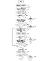
- FIGS. 9A and 9B show a flowchart of the feedback process according to the first embodiment of the present invention.
- the user inputs a predetermined target distance 42 using the input unit 35, and sets the variable ky_x indicating the target distance.
- the target distance 42 may be fixedly stored in the variable ky_x in advance.
- step S2 the BLE signal is received by the signal communication unit 14, and the distance measurement unit 16 calculates the distance between the self-propelled cleaner 1 and the charging stand 100 using the received BLE signal.
- This measurement distance is stored in the minimum measurement distance ky_min as the initial position distance.
- step S3 the vehicle travels forward by a fixed distance toward the current forward direction of the self-propelled cleaner 1.
- the fixed distance is not particularly limited, but is preferably as short as possible in order to increase accuracy. For example, a distance of about 10 cm to 20 cm may be set. Further, the fixed distance may be variable instead of a fixed value. For example, when the measurement distance is relatively long, the constant distance may be set long, and when the measurement distance becomes shorter than a predetermined value due to approaching the charging stand, the constant distance may be set short.
- step S4 it is checked whether or not an obstacle has been detected by the obstacle detector 34. If an obstacle is detected, the process proceeds to step S5, and if not, the process proceeds to step S6.
- the case where the obstacle is detected includes the case where the side surface of the self-propelled cleaner body contacts the object, or the case where the object is detected in the forward direction by the ultrasonic sensor 15.
- step S5 a predetermined direction change is performed, and the process returns to step S2.
- the predetermined direction change may be performed, for example, by stopping at a position where the obstacle is detected and rotating by an angle that can avoid the obstacle.
- the rotation operation may be performed at a random angle in addition to a preset angle such as 30 degrees, 60 degrees, 90 degrees, and 180 degrees.
- the ultrasonic sensor when rotating at a random angle or the like, it is preferable to use 15 for the ultrasonic sensor and confirm that there is no obstacle in the forward direction after the rotation, and then travel in the forward direction.
- the obstacle is a wall
- the direction may be changed at a random angle.
- the vehicle after traveling to the wall, the vehicle may travel along the wall.
- step S6 the distance measurement unit 16 calculates the distance between the self-propelled cleaner 1 and the charging stand 100 using the BLE signal received by the signal communication unit 14. This measurement distance is stored in a variable ky_tmp indicating the current measurement distance.
- step S7 it is checked whether ky_min ⁇ ky_tmp. That is, it is checked whether or not the current measurement distance ky_tmp measured at the current position where the self-propelled cleaner 1 is larger than the minimum distance (minimum measurement distance ky_min) among the distances measured so far. . If ky_min ⁇ ky_tmp, the process proceeds to step S8, and if not, the process proceeds to step S9.
- step S8 in order to change the traveling direction to a direction not away from the charging stand, a rotation operation of 180 degrees is performed at the current position.
- step S9 the current measurement distance ky_tmp is substituted for the minimum measurement distance ky_min, and the minimum measurement distance is updated.
- step S10 as in step S3, the vehicle is advanced by a certain distance.
- step S11 an obstacle detection check is performed as in step S4. If there is an obstacle, the process proceeds to step S12, the direction changing process is performed as in step S5, and the process returns to step S2. If there is no obstacle, the process proceeds to step S13, and the current measurement distance ky_tmp is measured and stored as in step S6.
- step S14 as in step S7, ky_min ⁇ ky_tmp is checked, and when the self-propelled cleaner 1 is closer to the charging stand 100 than the minimum measurement distance ky_min up to the previous time (ky_min ⁇ ky_tmp), the process proceeds to step S9. Returning, the processing from step S9 to S13 is repeated. On the other hand, when the self-propelled cleaner 1 travels a certain distance and travels away from the charging stand 100 with respect to the minimum measurement distance ky_min until the previous time (ky_min ⁇ ky_tmp), the process proceeds to step S15 and is the same as step S8. In addition, a rotation operation of 180 degrees is performed.
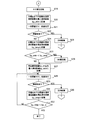
- step S16 the vehicle travels a fixed distance in the same manner as in step S3, and in step S17, the obstacle detection process similar to that in step S4 is performed. If there is an obstacle, the process proceeds to step S18, the direction is changed in the same manner as in step S5, and the process returns to step S2. On the other hand, if there is no obstacle, the process proceeds to step S19 in FIG. 9B, stops at the current position, and rotates 90 degrees to the left. However, it may be rotated 90 degrees to the right.
- the reason why the rotation is performed by 90 degrees is that the current position has already been advanced from the direction rotated by 180 degrees, and therefore, if the rotation is performed again by 180 degrees, it will return to the past position that has already been passed. . Therefore, an angle other than 180 degrees may be selected as the rotation angle, but in order to clearly set the subsequent course, for example, a rotation of 90 degrees may be selected as described above. After such a 90-degree rotation, traveling on a new straight line is performed.
- step S20 the measurement distance at the current position is set and stored as a temporary initial value (ky_min) of the minimum measurement distance.
- step S21 as in step S3, the vehicle moves forward by a fixed distance. Thereafter, from step S22 to S26, the same processing as from step S4 to S8 is repeated.
- step S27 as in step S9, the current measurement distance ky_tmp is updated to the new minimum measurement distance ky_min, and then the same processes as those in steps S10 to S13 described above are performed from steps S28 to S31.
- step S32 ky_tmp ⁇ ky_x is checked. If the current measurement distance ky_tmp is smaller than the target distance ky_x, it is determined that the self-propelled cleaner 1 has returned to a predetermined vicinity of the charging stand, and the feedback process is terminated. On the other hand, when the current measurement distance ky_tmp is larger than the target distance ky_x, it is still in the middle of returning, so the process returns to step S28 and the processes from step S28 to S31 are repeated. If the above feedback processing is executed, useless travel such as travel along the wall can be reduced, and the time required for the return processing to the charging stand can be shortened.
- Second Embodiment 10 to 12 are explanatory diagrams of the second embodiment of the feedback processing of the present invention.
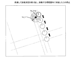
- 2nd Embodiment when it determines with the self-propelled electronic device moving in the direction away from a charging stand, measuring the distance to the charging stand which is a target object, the present position which performed the said determination
- the self-propelled electronic device is placed in the vicinity of the charging base by performing a 90-degree rotation operation in a certain direction and performing a combination of straight-line traveling and 90-degree rotation operation in the same direction as the above-described certain direction.
- the fixed direction may be either the left direction or the right direction, but not both directions are mixed, but one of the preset directions is used.
- FIG. 10A shows the initial position of the self-propelled cleaner 1 and the initial distance to the charging stand 100.
- the measured initial distance is stored as the minimum measurement distance ky_min.
- the slightly downward direction on the left is the forward direction of the self-propelled cleaner.
- the self-propelled cleaner 1 returns to a position closer to the charging stand than the target distance ky_x by using the following linear traveling and a 90-degree rotation operation to the left.
- FIG.10 (b) it advances by a fixed distance, measures the distance to the charging stand in the position, and memorize
- the self-propelled cleaner 1 has moved in a direction away from the charging stand 100. Therefore, as shown in FIG. 10C, the self-propelled cleaner 1 stops at the position of FIG. Rotate. Thereby, the forward direction becomes the lower right direction.
- the measurement distance at this position is stored as the minimum measurement distance ky_min.
- the distance from the position in FIG. 10C is further advanced by a certain distance, and the distance to the charging stand 100 at that position is measured and stored as the current measurement distance ky_tmp. Since the vehicle has moved in the direction away from the charging stand by the forward traveling in FIG. 10D, the vehicle stops at the current position in FIG. 10D and rotates 90 degrees to the left as shown in FIG. 11A. As a result, the slightly upward right is the forward direction. The measurement distance at this position is stored as the minimum measurement distance ky_min.
- the vehicle further moves forward by a certain distance, measures the distance to the charging stand at that position, and stores it as the current measurement distance ky_tmp.
- ky_tmp since ky_tmp in the position which advanced is smaller than ky_min, the self-propelled cleaner 1 is moving in the direction which approaches a charging stand. Therefore, ky_tmp is substituted for ky_min and updated.
- FIG.11 (c) it advances further by a fixed distance and similarly repeats the measurement of the present measurement distance ky_tmp.
- the distance to the charging stand is gradually shortened, and ky_tmp at the rightmost position is larger than the minimum measurement distance ky_min at the previous position. If you continue to move forward in the same direction, you will move further away from the charging stand. Therefore, as shown in FIG. 11D, the self-propelled cleaner 1 rotates 90 degrees counterclockwise at the rightmost position in FIG. 11C. As a result, the forward direction is the upper left direction.
- the measurement distance at this position is stored as the minimum measurement distance ky_min.
- the forward movement is repeated at regular intervals, and it is checked whether or not the current measurement distance ky_tmp is shorter than the target distance ky_x.
- ky_tmp ⁇ ky_x, it is considered that the self-propelled cleaner 1 has returned to the charging stand 100, and the feedback process is terminated. Thereafter, as described above, the operation of bringing the two connecting portions (51, 101) into contact is performed.
- the self-propelled cleaner 1 returns to the vicinity of the charging stand by the linear forward traveling and the three 90-degree left rotation operations. It is possible to prevent useless travel without traveling along the wall or random travel, and to shorten the time until returning to the charging stand.
- FIGS. 10 to 12 shows the worst case feedback processing, but if the 90 degree rotation operation is preset to the right rotation, two right rotation operations are performed. It is possible to return to the charging stand by linear forward traveling and return in a shorter time than the above.
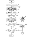
- FIG. 13 shows a flowchart of the feedback process of the second embodiment.
- the same step numbers are assigned to the same processes as those in the flowchart of FIG.
- a series of processing from step S1 to step S7 is the same processing as FIG.
- step S7 when ky_min ⁇ ky_tmp, the process proceeds to step S40.
- this corresponds to a case where the vehicle moves forward in a direction away from the charging stand.
- step S40 the counterclockwise rotation of 90 degrees is performed with the current position being controlled. Then, it returns to step S2 and repeats a series of processes.
- step S41 the process proceeds to step S41.
- step S41 ky_tmp ⁇ ky_x is checked as in step S32.
- the self-propelled cleaner 1 determines that it has returned to the vicinity of the target charging stand, and ends the feedback process.
- the process returns to step S2 and a series of processing is repeated.
- ⁇ Third Embodiment> If there is an obstacle in the traveling direction, it is not possible to go straight as it is, so it is necessary to change the traveling direction so as to avoid the obstacle. Therefore, even if the vehicle is rotated forward in a direction different from the traveling direction in which the obstacle is detected by the obstacle detection unit 34 (for example, 90 degrees to the left, 90 degrees to the right), and further travels forward in that direction. Good. Alternatively, a 180 degree rotation operation may be performed. Further, the rotation angle is not limited to 90 degrees and 180 degrees, and other angles may be used.
- the target object is a fixedly installed charging stand, but it is not limited to the fixedly installed one, and may be a mobile body having a signal communication unit.
- the self-propelled electronic device can follow the moving body while measuring the distance from the moving body.
Landscapes
- Engineering & Computer Science (AREA)
- Mechanical Engineering (AREA)
- Aviation & Aerospace Engineering (AREA)
- Radar, Positioning & Navigation (AREA)
- Remote Sensing (AREA)
- Physics & Mathematics (AREA)
- General Physics & Mathematics (AREA)
- Automation & Control Theory (AREA)
- Control Of Position, Course, Altitude, Or Attitude Of Moving Bodies (AREA)
- Electric Vacuum Cleaner (AREA)
Abstract
目標対象物(100)の位置に向かって自動走行する自走式電子機器(1)であって、車輪(22)の回転を制御して直線走行および回転動作をさせる走行制御部(21)と、前記目標対象物(100)から送信された無線信号を受信する信号通信部(14)と、前記受信された無線信号に基づいて、前記目標対象物(100)までの距離を測定する距離測定部(16)と、制御部(11)とを備え、自動走行中に前記距離測定部(16)によって測定された複数の測定距離に基づいて、自走式電子機器(1)が前記目標対象物(100)から遠ざかる方向に移動していると判定された場合に、前記制御部(11)が、現在位置で所定の回転動作を行わせた後、前記目標対象物(100)に近づく方向に直線走行と回転動作とを繰り返し行うことによって、前記目標対象物(100)の所定の近傍領域にまで移動させることを特徴とする自走式電子機器(1)。
Description
この発明は、自走式電子機器に関し、特に、充電台に自動的に帰還する機能を有する自走式電子機器に関する。
今日、室内を自動的に走行して掃除を行う自走式のロボット掃除機が利用されている。ロボット掃除機は、充電池を備え、充電池の残量が所定値以下となった場合に、室内の所定の位置に固定配置された充電台に帰還し、充電池を充電台に接続することにより充電を行う機能を有するものがある。
充電台への帰還方法としては、たとえば、充電台から所定の領域に向かって赤外線信号を送出しておき、ロボット掃除機に備えられた赤外線受信部によって上記赤外線信号を受信した場合に、充電台のある方向を検出して充電台の方向に向かって走行していく。
しかし、従来の充電台への帰還方法では、赤外線信号は、一定幅の指向性を持った無線信号なので、赤外線信号を受信できない領域が存在する。ロボット掃除機が、このような赤外線信号を受信できない位置にいた場合は、壁面に沿った走行(エッジ走行)や、ランダム走行をすることにより、赤外線信号を受信できる位置まで走行する必要があった。
すなわち、充電台の存在する方向を検出するまでに、無駄な走行をする場合もあるので、充電台へ帰還するまでの時間がかかる場合が多かった。
そこで、この発明は、以上のような事情を考慮してなされたものであり、充電が必要となった場合に、充電台へ戻るまでの無駄な移動をできるだけ少なくし、充電台へ帰還するまでの時間を短縮することのできる自走式電子機器を提供することを課題とする。
そこで、この発明は、以上のような事情を考慮してなされたものであり、充電が必要となった場合に、充電台へ戻るまでの無駄な移動をできるだけ少なくし、充電台へ帰還するまでの時間を短縮することのできる自走式電子機器を提供することを課題とする。
この発明は、目標対象物の位置に向かって自動走行する自走式電子機器であって、車輪の回転を制御して直線走行および回転動作をさせる走行制御部と、前記目標対象物から送信された無線信号を受信する信号通信部と、前記受信された無線信号に基づいて、前記目標対象物までの距離を測定する距離測定部と、制御部とを備え、自動走行中に前記距離測定部によって測定された複数の測定距離に基づいて、自走式電子機器が前記目標対象物から遠ざかる方向に移動していると判定された場合に、前記制御部が、現在位置で所定の回転動作を行わせた後、前記目標対象物に近づく方向に直線走行と回転動作とを繰り返し行うことによって、前記目標対象物の所定の近傍領域にまで移動させることを特徴とする自走式電子機器を提供するものである。
また、目標対象物の位置に向かって自動走行する自走式電子機器であって、車輪の回転を制御して直線走行および回転動作をさせる走行制御部と、前記目標対象物から送信された無線信号を受信する信号通信部と、前記受信された無線信号に基づいて、前記目標対象物までの距離を測定する距離測定部と、自動走行中に前記距離測定部によって測定された最新の現在位置での測定距離と、自動走行中の過去の複数の測定距離のうち最小の測定距離とを比較して大小関係を判定する距離判定部と、制御部とを備え、前記距離判定部が、前記現在位置での測定距離が、前記最小の測定距離よりも大きくなったと判定した場合に、前記制御部が、前記現在位置で所定の回転動作を行わせた後、前記目標対象物に近づく方向に直線走行と回転動作を繰り返し行うことによって、前記目標対象物の所定の近傍領域にまで移動させることを特徴とする自走式電子機器を提供するものである。
さらに、前記無線信号は、Bluetooth拡張仕様の一つで超低電力で通信可能なブルートゥース ローエナジーの規格で定められたBLE信号であり、前記信号通信部が受信したBLE信号の受信強度に基づいて、前記距離測定部が、前記目標対象物までの距離を測定することを特徴とする。
これによれば、受信したBLE信号に基づいて、目標対象物までの距離を測定しているので、走行方向に障害物があるか否かにかかわらず、自走式電子機器がBLE信号を受信できる距離内にいる限り、自走式電子機器と目標対象物との間の直線距離を算出することができる。
これによれば、受信したBLE信号に基づいて、目標対象物までの距離を測定しているので、走行方向に障害物があるか否かにかかわらず、自走式電子機器がBLE信号を受信できる距離内にいる限り、自走式電子機器と目標対象物との間の直線距離を算出することができる。
また、前記自走式電子機器が前記目標対象物から遠ざかる方向に移動していると判定された場合に、前記制御部が、180度の回転動作あるいは90度の回転動作を行わせ、直線走行と、180度の回転動作と、90度の回転動作とを組み合わせた走行を行うことによって、前記目標対象物の所定の近傍領域にまで移動させることを特徴とする。
これによれば、直線走行と、180度の回転動作と、90度の回転動作とを組み合わせた走行を行っているので、壁に沿った走行やランダム走行を行うことによって目標対象物に近づける場合に比べて、無駄な走行を減少させることができ、目標対象物の近傍領域に移動するまでの時間を短縮することができる。
これによれば、直線走行と、180度の回転動作と、90度の回転動作とを組み合わせた走行を行っているので、壁に沿った走行やランダム走行を行うことによって目標対象物に近づける場合に比べて、無駄な走行を減少させることができ、目標対象物の近傍領域に移動するまでの時間を短縮することができる。
また、前記自走式電子機器が前記目標対象物から遠ざかる方向に移動していると判定された場合に、前記制御部が、上記判定をした現在位置で一定方向の90度の回転動作を行わせ、直線走行と、前記一定方向と同一方向の90度の回転動作とを組み合わせた走行を行うことによって、前記目標対象物の所定の近傍領域にまで移動させることを特徴とする。
これによれば、直線走行と、一定方向の90度の回転動作とを組み合わせた走行を行っているので、壁に沿った走行やランダム走行を行うことによって目標対象物に近づける場合に比べて、無駄な走行を減少させることができ、目標対象物の近傍領域に移動するまでの時間を短縮することができる。
これによれば、直線走行と、一定方向の90度の回転動作とを組み合わせた走行を行っているので、壁に沿った走行やランダム走行を行うことによって目標対象物に近づける場合に比べて、無駄な走行を減少させることができ、目標対象物の近傍領域に移動するまでの時間を短縮することができる。
また、前記回転動作の角度は、ランダムに生成された任意の角度、あるいは、予め設定された固定値のどちらでもよい。
また、前記目標対象物は移動体でもよく、自走式電子機器は、その移動体に追随するようにしてもよい。
また、前記目標対象物は移動体でもよく、自走式電子機器は、その移動体に追随するようにしてもよい。
また、前記自走式電子機器は、充電池および掃除機能を備えた自走式掃除機であり、前記目標対象物は充電台であり、前記制御部が、前記自走式掃除機の充電池の電池残量が所定値以下に減少した場合に、充電台へ帰還する必要があると判断し、前記自走式掃除機を前記充電台に帰還させる機能を実行させることを特徴とする。
これによれば、自走式掃除機から充電台までの距離を測定し、その測定距離に基づいて、直線走行と回転動作とを繰り返し行わせて、自走式掃除機を充電台まで帰還させるので、自走式掃除機の充電台への帰還処理にかかる時間を短縮することができる。
これによれば、自走式掃除機から充電台までの距離を測定し、その測定距離に基づいて、直線走行と回転動作とを繰り返し行わせて、自走式掃除機を充電台まで帰還させるので、自走式掃除機の充電台への帰還処理にかかる時間を短縮することができる。
この発明によれば、自走式電子機器から目標対象物までの距離を測定し、その測定距離に基づいて目標対象物に近づく方向に直線走行と回転動作とを繰り返し行っているので、自走式電子機器の無駄な走行を減少させ、自走式電子機器が目標対象物の所定の近傍領域に移動するまでの時間を短縮させることができる。
以下、図に示す実施例に基づいて、この発明を説明する。
なお、これによって、この発明が限定されるものではない。
なお、これによって、この発明が限定されるものではない。
<自走式電子機器の構成>
この発明の自走式電子機器は、目標対象物の位置に向かって自動走行する電子機器である。
以下に、この発明の自走式電子機器の一実施例として、充電池および掃除機能を備えた「自走式掃除機」の構成について説明する。また、この場合、上記目標対象物は、充電台とする。
ただし、この発明は、少なくとも充電池を備え、自動走行制御を行って、自動走行によって目標対象物の近傍領域にまで移動する機能を有する電子機器であればよく、自走式掃除機に限定するものではない。また、目標対象物も、充電台に限定するものではない。
この発明の自走式電子機器は、目標対象物の位置に向かって自動走行する電子機器である。
以下に、この発明の自走式電子機器の一実施例として、充電池および掃除機能を備えた「自走式掃除機」の構成について説明する。また、この場合、上記目標対象物は、充電台とする。
ただし、この発明は、少なくとも充電池を備え、自動走行制御を行って、自動走行によって目標対象物の近傍領域にまで移動する機能を有する電子機器であればよく、自走式掃除機に限定するものではない。また、目標対象物も、充電台に限定するものではない。
たとえば、自走式電子機器には、空気吸引を行い清浄化した空気を排気する自走式空気清浄機、イオンを発生させる自走式イオン発生機、ユーザに対して必要な情報を提示する機能やユーザが要求した機能を実行する自走式ロボット等も含まれる。目標対象物としては、後述する信号通信部を有するあらゆる有体物が含まれる。
図1に、この発明の自走式掃除機の一実施例の構成ブロック図を示す。
図1において、この発明の自走式掃除機(以下、掃除機またはクリーナとも呼ぶ)は、主として、制御部11、充電池12、電池残量検出部13、信号通信部14、超音波センサ15、距離測定部16、距離判定部17、赤外線受信部18、走行制御部21、車輪22、吸気口31、排気口32、集塵部33、障害検知部34、入力部35、記憶部41、充電台接続部51を備える。
図1において、この発明の自走式掃除機(以下、掃除機またはクリーナとも呼ぶ)は、主として、制御部11、充電池12、電池残量検出部13、信号通信部14、超音波センサ15、距離測定部16、距離判定部17、赤外線受信部18、走行制御部21、車輪22、吸気口31、排気口32、集塵部33、障害検知部34、入力部35、記憶部41、充電台接続部51を備える。
また、掃除を行う部屋などの所定の位置に充電台100を固定設置する。充電台100と自走式掃除機1を接続することにより、自走式掃除機1は充電台と接触した状態で充電台からの電力の供給を受け、自走式掃除機1の充電池12を充電する。また、自走式掃除機1は、充電台100から離れ自動走行しながら掃除機能を実行する。
この発明の自走式掃除機1は、設置された場所の床面を自走しながら、床面上の塵埃を含む空気を吸い込み、塵埃を除去した空気を排気することにより床面上を掃除する掃除ロボットである。この発明の自走式掃除機1は、掃除が終了すると、自律的に充電台100に帰還する機能を有する。
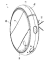
図2に、この発明の自走式掃除機の一実施例の概略斜視図を示す。
図2に、この発明の自走式掃除機の一実施例の概略斜視図を示す。
図2において、本発明の自走式掃除機1は、円盤形の筐体2を備え、この筐体2の内部および外部に、回転ブラシ、サイドブラシ10、集塵部33、電動送風機、複数の駆動輪からなる車輪22、信号通信部14、赤外線受信部18、図1に示したその他の構成要素が設けられている。
図2において、赤外線受信部18が配置されている部分を前方部、従動輪である後輪が配置されている部分を後方部、筐体内部に信号通信部14や集塵部33が配置されている部分を中間部と呼ぶ。
図2において、赤外線受信部18が配置されている部分を前方部、従動輪である後輪が配置されている部分を後方部、筐体内部に信号通信部14や集塵部33が配置されている部分を中間部と呼ぶ。
筐体2は、吸気口31を有する平面視円形の底板と、筐体2に収容する集塵部33を出し入れする際に開閉する蓋部3を中央部分に有している天板2bと、底板および天板2bの外周部に沿って設けられた平面視円環形の側板2cとを備えている。また、底板には一対の駆動輪および後輪の下部を筐体2内から外部へ突出させる複数の孔部が形成され、天板2bにおける前方部と中間部との境界付近には排気口32が形成されている。なお、側板2cは、前後に二分割されており、側板前部はバンパーとして機能する。
自走式掃除機1は、一対の駆動輪が同一方向に正回転して前進し、同一方向に逆回転して後退し、互いに逆方向に回転することにより静止した状態で旋回する。例えば、掃除機1は、掃除領域の周縁に到達した場合および進路上の障害物に衝突した場合、駆動輪が停止し、一対の駆動輪を互いに逆方向に回転して向きを変える。これにより、掃除機1は、設置場所全体あるいは所望範囲全体に障害物を避けながら自走する。
また、自走式掃除機1は、後述するように、信号通信部14によって、充電台100の信号通信部102から出射される無線信号を受信して充電台100との距離を測定し、たとえば掃除が終了した場合、充電池12の充電残量が少なくなった場合、あるいは設定された掃除タイマーの設定時間が経過した場合に、測定距離が短くなるように、自動的に目標対象物である充電台に近づく方向に向かって、直線的な走行と回転動作とを繰り返して進行し、充電台100の近傍領域にまで帰還する。
ただし、障害物があれば、それを避けながら、充電台100の方向へ移動する。
ただし、障害物があれば、それを避けながら、充電台100の方向へ移動する。
以下、図1に示す各構成要素を説明する。
図1の制御部11は、掃除機1の各構成要素の動作を制御する部分であり、主として、CPU、ROM、RAM、I/Oコントローラ、タイマー等からなるマイクロコンピュータによって実現される。
CPUは、ROM等に予め格納された制御プログラムに基づいて、各ハードウェアを有機的に動作させて、この発明の掃除機能、走行機能などを実行する。
図1の制御部11は、掃除機1の各構成要素の動作を制御する部分であり、主として、CPU、ROM、RAM、I/Oコントローラ、タイマー等からなるマイクロコンピュータによって実現される。
CPUは、ROM等に予め格納された制御プログラムに基づいて、各ハードウェアを有機的に動作させて、この発明の掃除機能、走行機能などを実行する。
充電池12は、掃除機1の各機能要素に対して電力を供給する部分であり、主として、掃除機能および走行制御を行うための電力を供給する部分である。たとえば、リチウムイオン電池、ニッケル水素電池、Ni-Cd電池、などの充電池が用いられる。
充電池12の充電は、掃除機1と充電台100とを接続した状態で行われる。
掃除機1と充電台100との接続は、互いの接続部(51,101)である露出した充電端子どうしを接触させることにより行う。
充電池12の充電は、掃除機1と充電台100とを接続した状態で行われる。
掃除機1と充電台100との接続は、互いの接続部(51,101)である露出した充電端子どうしを接触させることにより行う。
電池残量検出部13は、充電池の残りの容量(電池残量)を検出する部分であり、たとえば、フル充電状態に対して、現在の残容量をパーセント(%)で表した数値を出力する。ここで検出された電池残量(%)に基づいて、充電台100の方へ帰還するべきか否かを判断し、帰還する場合は、後述するような帰還処理を実行する。
走行制御部21は、自走式掃除機1の自律走行の制御をする部分であり、主として上記した車輪22の回転を制御して、主として直線走行および回転動作をさせることによって、自動的に移動させる部分である。
車輪を駆動させることにより、掃除機1の前進、後退、回転、静止などの動作を行わせる。
後述するように、自走式電子機器の帰還処理を行うために回転動作をする場合、その回転動作の角度は、ランダムに生成された任意の角度、あるいは、予め設定された固定値のいずれかであってもよい。
車輪を駆動させることにより、掃除機1の前進、後退、回転、静止などの動作を行わせる。
後述するように、自走式電子機器の帰還処理を行うために回転動作をする場合、その回転動作の角度は、ランダムに生成された任意の角度、あるいは、予め設定された固定値のいずれかであってもよい。
集塵部33は、室内のゴミやちりを集める掃除機能を実行する部分であり、主として、図示しない集塵容器と、フィルタ部と、集塵容器およびフィルタ部を覆うカバー部とを備える。
また、吸気口31と連通する流入路と、排気口32と連通する排出路とを有し、吸気口31から吸い込まれた空気を流入路を介して集塵容器内に導き、集塵後の空気を排出路を介して排気口32から外部へ放出する。
吸気口31および排気口32は、それぞれ掃除のための空気の吸気および排気を行う部分であり、前記したような位置に形成される。
また、吸気口31と連通する流入路と、排気口32と連通する排出路とを有し、吸気口31から吸い込まれた空気を流入路を介して集塵容器内に導き、集塵後の空気を排出路を介して排気口32から外部へ放出する。
吸気口31および排気口32は、それぞれ掃除のための空気の吸気および排気を行う部分であり、前記したような位置に形成される。
障害検知部34は、掃除機1が走行中に、室内の机やいすなどの障害物に接触又は近づいたことを検知する部分であり、たとえば、マイクロスイッチ、超音波センサ、赤外線測距センサなどからなる接触センサや非接触センサ、又は障害物センサが用いられ、筐体2の側板2Cの前部に配置される。
CPUは、障害検知部34から出力された信号に基づいて、障害物の存在する位置を認識する。認識された障害物の位置情報に基づいて、その障害物を避けて次に走行すべき方向を決定する。
CPUは、障害検知部34から出力された信号に基づいて、障害物の存在する位置を認識する。認識された障害物の位置情報に基づいて、その障害物を避けて次に走行すべき方向を決定する。
入力部35は、ユーザが、掃除機1の動作を指示入力する部分であり、掃除機1の筐体表面に、操作パネル、あるいは操作ボタンとして設けられる。
あるいは、入力部35としては、掃除機本体とは別に、リモコンユニットを設け、ユーザがこのリモコンユニットに設けられた操作ボタンを押すことにより、赤外線や無線電波信号を送出し、無線通信により動作の指示入力をしてもよい。
入力部35としては、たとえば、電源スイッチ、起動スイッチ、主電源スイッチ、充電要求スイッチ、その他のスイッチ(運転モードスイッチ,タイマースイッチ)などが設けられる。
あるいは、入力部35としては、掃除機本体とは別に、リモコンユニットを設け、ユーザがこのリモコンユニットに設けられた操作ボタンを押すことにより、赤外線や無線電波信号を送出し、無線通信により動作の指示入力をしてもよい。
入力部35としては、たとえば、電源スイッチ、起動スイッチ、主電源スイッチ、充電要求スイッチ、その他のスイッチ(運転モードスイッチ,タイマースイッチ)などが設けられる。
記憶部41は、掃除機1の各種機能を実現するために必要な情報や、プログラムを記憶する部分であり、RAMやROM等の半導体素子、ハードディスク、フラッシュメモリ等の記憶媒体が用いられる。
記憶部41には、主として、目標距離42、最小測定距離43、現在測定距離44、電池情報45などが記憶される。以下の実施例では、目標距離をky_x、最小測定距離をky_min、現在測定距離をky_tmpとする。
電池情報45には、電池残量検出部13によって検出された電池残量(%)や、充電台への帰還を決定するために検出された電池残量と比較する判定値(残量しきい値)などが含まれる。
この発明では、掃除機1が自ら充電台100へ帰還する処理を実行するが、制御部11が、充電台と接触した状態に帰還する必要があると判断した場合に、その帰還処理を実行する。
記憶部41には、主として、目標距離42、最小測定距離43、現在測定距離44、電池情報45などが記憶される。以下の実施例では、目標距離をky_x、最小測定距離をky_min、現在測定距離をky_tmpとする。
電池情報45には、電池残量検出部13によって検出された電池残量(%)や、充電台への帰還を決定するために検出された電池残量と比較する判定値(残量しきい値)などが含まれる。
この発明では、掃除機1が自ら充電台100へ帰還する処理を実行するが、制御部11が、充電台と接触した状態に帰還する必要があると判断した場合に、その帰還処理を実行する。
充電台と接触した状態に帰還する必要があると判断する場合とは、充電池12の電池残量が少なくなってきた場合、ユーザにより充電要求スイッチが押し下げられた場合、あるいはユーザがリモコンを利用して帰還指示入力を行った場合等がある。
たとえば、電池残量検出部13によって検出された充電池の電池残量が、電池情報45として記憶されている残量しきい値以下に減少した場合に、充電台へ帰還する必要があると判断し、自走式掃除機を充電台に帰還させる機能(帰還処理)を実行する。
あるいは、自動走行中に、充電要求スイッチが押し下げられた場合に、充電台へ帰還する必要があると判断し、帰還処理を実行する。
たとえば、電池残量検出部13によって検出された充電池の電池残量が、電池情報45として記憶されている残量しきい値以下に減少した場合に、充電台へ帰還する必要があると判断し、自走式掃除機を充電台に帰還させる機能(帰還処理)を実行する。
あるいは、自動走行中に、充電要求スイッチが押し下げられた場合に、充電台へ帰還する必要があると判断し、帰還処理を実行する。
目標距離42は、帰還処理において、自走式掃除機1が、充電台100の近傍にまで戻ってきたと判断するための距離であり、予め、記憶部41に記憶される。
たとえば、充電台100の信号通信部102と自走式掃除機1の信号通信部14との間の現在測定距離(ky_tmp)44が、記憶部41に記憶された目標距離(ky_x)42よりも短い場合(ky_x>ky_tmp)、自走式掃除機1は、充電台100まで戻ってきたと判断する。
たとえば、充電台100の信号通信部102と自走式掃除機1の信号通信部14との間の現在測定距離(ky_tmp)44が、記憶部41に記憶された目標距離(ky_x)42よりも短い場合(ky_x>ky_tmp)、自走式掃除機1は、充電台100まで戻ってきたと判断する。
現在測定距離(ky_tmp)44は、自走式掃除機1の現在位置と、充電台100との間の距離を測定したものであり、最小測定距離(ky_min)43は、距離測定部16によって測定された現在測定距離44のうち最小値を記憶したものである。
新たに測定された現在測定距離44が、記憶部41に記憶された最小測定距離43よりも小さくなった場合には、この新たに測定された現在測定距離44が、最小測定距離43に置き換えられる。
新たに測定された現在測定距離44が、記憶部41に記憶された最小測定距離43よりも小さくなった場合には、この新たに測定された現在測定距離44が、最小測定距離43に置き換えられる。
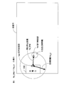
図3に、記憶部に記憶される目標距離と測定距離との関係の説明図を示す。
図3(a)は、自走式掃除機1が、充電台100から十分離れた位置にいる場合(ky_tmp>ky_x)を示している。
図3(b)は、自走式掃除機1が、充電台100の所定の近傍領域にまで戻ってきた場合(ky_tmp<ky_x)を示している。
図3において、現在測定距離44は、充電台100の信号通信部102と自走式掃除機1の信号通信部14との間の距離の現在の測定値ky_tmpとして示している。
図3(a)は、自走式掃除機1が、充電台100から十分離れた位置にいる場合(ky_tmp>ky_x)を示している。
図3(b)は、自走式掃除機1が、充電台100の所定の近傍領域にまで戻ってきた場合(ky_tmp<ky_x)を示している。
図3において、現在測定距離44は、充電台100の信号通信部102と自走式掃除機1の信号通信部14との間の距離の現在の測定値ky_tmpとして示している。
また、目標距離ky_xは、信号通信部102を中心とする円の半径を示しており、この円の中に自走式掃除機1の信号通信部14が入ったときに、自走式掃除機1が充電台100の近傍に帰還したと判断するものとする。
すなわち、自走式掃除機1が、この円の中にまで戻ってきた場合、所定の動作を行うことにより、相互の接続部(51,101)を接続させることができるものとし、目標距離ky_xは、そのような距離が予め設定される。たとえば、目標距離ky_xとしては、30cm程度が設定される。
すなわち、自走式掃除機1が、この円の中にまで戻ってきた場合、所定の動作を行うことにより、相互の接続部(51,101)を接続させることができるものとし、目標距離ky_xは、そのような距離が予め設定される。たとえば、目標距離ky_xとしては、30cm程度が設定される。
後述するこの発明の帰還処理は、図3(a)に示すように、現在測定距離(ky_tmp)44が十分に長い位置に存在する自走式掃除機1が、図3(b)に示すように、自走式掃除機1が、ky_tmp<ky_xとなる位置に戻ってくるまでの処理を示している。
図1の信号通信部14は、目標対象物である充電台100の信号通信部102から送信された無線信号を受信(検出)する部分である。信号通信部14の素子としては、送信される無線信号を受信できる一般的なデバイスが利用できる。
以下の実施例では、充電台100から送信される無線信号としては、たとえば、ブルートゥース ローエナジー(BLE:Bluetooth Low Energy)の規格で定められた信号を用いるものとする。以下、この信号を、BLE信号と呼ぶ。
充電台からBLE信号が送信される場合は、信号通信部14も、BLEによる通信が可能な受信デバイスが用いられる。この発明では、信号通信部14が受信したBLE信号に含まれる送信側の信号送出レベルと、受信側で実際に受信した信号の受信強度に基づいて、目標対象物までの距離を測定することを特徴とする。
以下の実施例では、充電台100から送信される無線信号としては、たとえば、ブルートゥース ローエナジー(BLE:Bluetooth Low Energy)の規格で定められた信号を用いるものとする。以下、この信号を、BLE信号と呼ぶ。
充電台からBLE信号が送信される場合は、信号通信部14も、BLEによる通信が可能な受信デバイスが用いられる。この発明では、信号通信部14が受信したBLE信号に含まれる送信側の信号送出レベルと、受信側で実際に受信した信号の受信強度に基づいて、目標対象物までの距離を測定することを特徴とする。
BLEは、今日、近距離無線通信の一つの通信方式として用いられるブルートゥースの新しい規格であり、2.4GHz帯の電波を利用した無線通信を行うものである。
BLEは、最大通信速度が1Mbpsであり、省電力性を特徴とする。
BLEは、最大通信速度が1Mbpsであり、省電力性を特徴とする。
この発明では、BLE信号の送信デバイスからなる信号通信部102から出力される無線信号を、信号通信部14によって受信することにより、信号通信部102と信号通信部14との距離ky_tmpを測定する。
たとえば、信号通信部102から出力されるBLE信号内に含まれる送信側の信号送出レベル情報と、受信側で実際に受信した信号の受信信号強度を比較することにより、伝送による信号の伝送損失を求め、その伝送損失に基づいて距離を演算することにより上記距離ky_tmpを計算すればよい。
あるいは、計測しておいたBLE信号の受信強度と距離との関係テーブルを記憶部に予め記憶しておき、受信したBLE信号の測定値と関係テーブルの受信強度とを比較することによって、距離を求めてもよい。
たとえば、信号通信部102から出力されるBLE信号内に含まれる送信側の信号送出レベル情報と、受信側で実際に受信した信号の受信信号強度を比較することにより、伝送による信号の伝送損失を求め、その伝送損失に基づいて距離を演算することにより上記距離ky_tmpを計算すればよい。
あるいは、計測しておいたBLE信号の受信強度と距離との関係テーブルを記憶部に予め記憶しておき、受信したBLE信号の測定値と関係テーブルの受信強度とを比較することによって、距離を求めてもよい。
また、BLE信号は、指向性を有する赤外線とは異なる波長の長い電波であるため、信号通信部102から、360度のあらゆる方向に送信される。
したがって、赤外線を遮るような障害物が、充電台100と自走式掃除機1との間にあったとしても、BLE信号を受信することができ、両者(1,100)間の距離を測定することができる。
したがって、赤外線を遮るような障害物が、充電台100と自走式掃除機1との間にあったとしても、BLE信号を受信することができ、両者(1,100)間の距離を測定することができる。
超音波センサ15は、部屋の壁や机などの対象物までの距離を検出するものであり、超音波を発信する送波器と、対象物からの反射波を受信する受波器とから構成される。
超音波センサ15は、主として、壁などの障害物までの距離の測定に用いられる。
超音波センサ15は、主として、壁などの障害物までの距離の測定に用いられる。
距離測定部16は、受信された無線信号に基づいて、目標対象物である充電台100までの距離を測定する部分である。具体的には、信号通信部14によって受信されたBLE信号を用い、BLE信号の受信強度を検出し、自走式掃除機1と充電台100との距離を計算する。
距離判定部17は、距離測定部16によって計算された距離と、比較対象となる距離との大小関係を判定する部分である。
たとえば、自動走行中に、距離測定部16によって測定された最新の現在位置での測定距離と、自動走行中の過去の複数の測定距離のうち最小の測定距離とを比較して大小関係を判定する部分である。
自走式電子機器が目標対象物から遠ざかる方向に移動していると判断した場合、すなわち、現在位置での測定距離が、最小の測定距離よりも大きくなったと判定した場合(ky_tmp>ky_min)は、後述するように、現在位置で所定の回転動作を行わせた後、目標対象物である充電台に近づく方向に、直線走行と回転動作を繰り返し行うことによって、充電台の所定の近傍にまで移動させる。
たとえば、自動走行中に、距離測定部16によって測定された最新の現在位置での測定距離と、自動走行中の過去の複数の測定距離のうち最小の測定距離とを比較して大小関係を判定する部分である。
自走式電子機器が目標対象物から遠ざかる方向に移動していると判断した場合、すなわち、現在位置での測定距離が、最小の測定距離よりも大きくなったと判定した場合(ky_tmp>ky_min)は、後述するように、現在位置で所定の回転動作を行わせた後、目標対象物である充電台に近づく方向に、直線走行と回転動作を繰り返し行うことによって、充電台の所定の近傍にまで移動させる。
また、後述するように、充電台100の近傍にまで帰還してきたことを判断するための目標距離(ky_x)と、距離測定部16によって計算された現在の測定距離(ky_tmp)とを比較し、ky_tmp<ky_xの場合には、自走式掃除機1は、充電台100の近傍に帰還したと判断する。
赤外線受信部18は、充電台の赤外線送信部106から出力された赤外線信号を受信する部分であり、赤外線信号は、自走式掃除機の帰還処理および充電台への接続処理に用いられる。
充電台接続部51は、充電池12を充電させるための電力を入力するための端子である。
この充電台接続部51と、充電台100の掃除機接続部101とを物理的に接触させることにより、充電台100の電力供給部104から与えられる電力を、充電池12に供給し充電する。
充電台接続部51は、掃除機接続部101と接触させるために、掃除機1本体の側面に露出した状態で形成される。
自走式掃除機1は上記のように、充電台の近傍に帰還した後、赤外線受信部18によって受信された赤外線を利用して、充電台接続部51と掃除機接続部101とを接触させるように、接続処理を行う。
充電台接続部51は、充電池12を充電させるための電力を入力するための端子である。
この充電台接続部51と、充電台100の掃除機接続部101とを物理的に接触させることにより、充電台100の電力供給部104から与えられる電力を、充電池12に供給し充電する。
充電台接続部51は、掃除機接続部101と接触させるために、掃除機1本体の側面に露出した状態で形成される。
自走式掃除機1は上記のように、充電台の近傍に帰還した後、赤外線受信部18によって受信された赤外線を利用して、充電台接続部51と掃除機接続部101とを接触させるように、接続処理を行う。
この発明の自走式掃除機1は、以上のような構成に加えて、他にも必要な構成や機能を備えてもよい。
たとえば、掃除中あるいは静止状態において、イオンを発生する構成(イオン発生器)を備えて、除菌や消臭(または脱臭)を行うようにしてもよい。
また、掃除処理を実行する時間を設定するタイマースイッチを設け、タイマースイッチの入(ON)操作がされた場合には、予め設定された時間(たとえば60分間)のカウントを開始し、その設定時間が経過するまで掃除処理を実行するようにしてもよい。
この設定時間が経過した後は、掃除処理を中止し、自動的に充電台に帰還するようにしてもよい。
たとえば、掃除中あるいは静止状態において、イオンを発生する構成(イオン発生器)を備えて、除菌や消臭(または脱臭)を行うようにしてもよい。
また、掃除処理を実行する時間を設定するタイマースイッチを設け、タイマースイッチの入(ON)操作がされた場合には、予め設定された時間(たとえば60分間)のカウントを開始し、その設定時間が経過するまで掃除処理を実行するようにしてもよい。
この設定時間が経過した後は、掃除処理を中止し、自動的に充電台に帰還するようにしてもよい。
<充電台の構成>
図1において、充電台100は、主として、掃除機接続部101、信号通信部102、制御部103、電力供給部104、赤外線送信部106とを備え、室内の壁などに配置された商用電源105のコンセントからのAC電源電力の供給を受ける。
電力供給部104は、商用電源105からの交流電力を受け入れ、掃除機1を充電することのできる直流電力に変換し、掃除機接続部101に与える部分である。
図1において、充電台100は、主として、掃除機接続部101、信号通信部102、制御部103、電力供給部104、赤外線送信部106とを備え、室内の壁などに配置された商用電源105のコンセントからのAC電源電力の供給を受ける。
電力供給部104は、商用電源105からの交流電力を受け入れ、掃除機1を充電することのできる直流電力に変換し、掃除機接続部101に与える部分である。
赤外線送信部106は、赤外線信号を送信する部分である。
信号通信部102は、無線信号を送信(発信)する部分である。たとえば、BLEの規格に基づいた信号を送信するBLEの通信デバイスが用いられる。
充電台100の制御部103は、充電台の各種機能を実現する部分であり、主として、BLE信号の通信処理や赤外線信号の発信処理と、充電電力の供給制御を行う。制御部103は、CPU、ROM、RAM、I/Oコントローラ、タイマー等からなるマイクロコンピュータにより実現できる。
信号通信部102は、無線信号を送信(発信)する部分である。たとえば、BLEの規格に基づいた信号を送信するBLEの通信デバイスが用いられる。
充電台100の制御部103は、充電台の各種機能を実現する部分であり、主として、BLE信号の通信処理や赤外線信号の発信処理と、充電電力の供給制御を行う。制御部103は、CPU、ROM、RAM、I/Oコントローラ、タイマー等からなるマイクロコンピュータにより実現できる。
<第1実施形態>
ここでは、自走式掃除機が充電台へ帰還する処理の第1実施形態について説明する。
第1実施形態では、自走式掃除機1の現在位置と充電台100との間の距離を測定しながら、目標対象物から遠ざかる方向に移動していると判定された場合に、180度の回転動作あるいは90度の回転動作を行わせ、直線走行と、180度回転と、90度回転とを組み合わせた走行を繰り返し実行することにより、自走式掃除機1を充電台のある方向へ進行させ、上記した目標距離42の円内にまで移動させる帰還方法を示す。
帰還処理の説明をわかりやすくするために、走行する空間内に障害物は存在しないものとする。
ここでは、自走式掃除機が充電台へ帰還する処理の第1実施形態について説明する。
第1実施形態では、自走式掃除機1の現在位置と充電台100との間の距離を測定しながら、目標対象物から遠ざかる方向に移動していると判定された場合に、180度の回転動作あるいは90度の回転動作を行わせ、直線走行と、180度回転と、90度回転とを組み合わせた走行を繰り返し実行することにより、自走式掃除機1を充電台のある方向へ進行させ、上記した目標距離42の円内にまで移動させる帰還方法を示す。
帰還処理の説明をわかりやすくするために、走行する空間内に障害物は存在しないものとする。
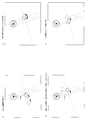
まず、図4から図7に、第1実施形態の帰還処理の概略説明図を示す。
図4(a)は、充電台100の位置と、この実施例における自走式掃除機1の初期位置とを示している。ここで、充電台100の信号通信部102を円の中心と考え、自走式掃除機1が帰還したと判断する距離(目標距離:ky_x)を、その円の半径とする。
図4(a)は、充電台100の位置と、この実施例における自走式掃除機1の初期位置とを示している。ここで、充電台100の信号通信部102を円の中心と考え、自走式掃除機1が帰還したと判断する距離(目標距離:ky_x)を、その円の半径とする。
また、自走式掃除機1の距離測定部16が、信号通信部14が受信したBLE信号を用いて、自走式掃除機1の初期位置と充電台100との現在の距離(図4(a)の破線で示した直線)を算出し、その距離を、最小測定距離43を示す変数ky_minに記憶する。
この初期位置で測定した距離を、仮の最小測定距離(ky_min)とする。
図4に示す自走式掃除機1の丸印は、走行の前方方向を示しているものとし、通常の直線的な前進走行をする場合は、この丸印の前方に向かって進行するものとする。
このような初期位置から、自走式掃除機1が、目標距離(ky_x)を半径とする円の中に入るようになるまで、以下に示すような帰還処理を実行する。
この初期位置で測定した距離を、仮の最小測定距離(ky_min)とする。
図4に示す自走式掃除機1の丸印は、走行の前方方向を示しているものとし、通常の直線的な前進走行をする場合は、この丸印の前方に向かって進行するものとする。
このような初期位置から、自走式掃除機1が、目標距離(ky_x)を半径とする円の中に入るようになるまで、以下に示すような帰還処理を実行する。
図4(b)において、自走式掃除機1は、一定距離だけ前進し、その位置での自走式掃除機1と充電台100との距離を測定し、現在測定距離44(ky_tmp)に記憶する。
図4(b)では、図の左ややななめ下方向へ進行するものとする。そして、現在測定距離44(ky_tmp)と、最小測定距離43(ky_min)とを比較する。
図4(b)では、図の左ややななめ下方向へ進行するものとする。そして、現在測定距離44(ky_tmp)と、最小測定距離43(ky_min)とを比較する。
図4(c)は、上記2つの距離の比較の結果、ky_tmp>ky_minとなった場合、すなわち、自走式掃除機1が移動することによって、測定距離が遠くなった場合を示している。
この場合、このまま前進すると、充電台100からさらに遠ざかることになるので、充電台100に近づくために、図4(b)の測定位置に静止した状態で、180度回転する。
図4(b)と図4(c)の自走式掃除機1の位置は同一とする。
この場合、このまま前進すると、充電台100からさらに遠ざかることになるので、充電台100に近づくために、図4(b)の測定位置に静止した状態で、180度回転する。
図4(b)と図4(c)の自走式掃除機1の位置は同一とする。
図4(c)のように、180度回転することによって、自走式掃除機1の前進方向は、図4(b)とは逆方向となる。
図4(d)において、図4(b)の説明で示したのと同様に、自走式掃除機1は、一定距離だけ前進してその位置での充電台100までの距離を測定し、現在測定距離(ky_tmp)として記憶することを繰り返す。
図4(d)において、図4(b)の説明で示したのと同様に、自走式掃除機1は、一定距離だけ前進してその位置での充電台100までの距離を測定し、現在測定距離(ky_tmp)として記憶することを繰り返す。
このとき、ky_tmp≦ky_minの場合、すなわち、自走式掃除機1は、前回までの最小測定距離ky_minよりも現在測定距離ky_tmpの方が短いか同一である場合、充電台100に近づく方向に向かって進行していると考えられる。
したがって、現在の前進方向と同じ方向に、直線的な走行を継続させる。
また、ky_tmp<ky_minとなった場合は、ky_tmpの値を、新たな最小測定距離43と考えて、ky_minに代入する。
したがって、現在の前進方向と同じ方向に、直線的な走行を継続させる。
また、ky_tmp<ky_minとなった場合は、ky_tmpの値を、新たな最小測定距離43と考えて、ky_minに代入する。
図5(a)は、充電台100に近づくように、図4(d)と同様の方向に走行した場合を示している。この位置で現在測定距離44(ky_tmp)が、最小測定距離43(ky_min)に設定されている。
図5(b)は、図5(a)の位置からさらに一定距離前進した場合を示している。このとき、ky_tmp>ky_minとなったとする。
すなわち、図5(a)の位置に比べて、充電台100から遠ざかる方向に進行したとする。このまま同じ方向に前進すると、充電台100からますます遠ざかってしまうので、進行方向を180度変更する。
すなわち、図5(a)の位置に比べて、充電台100から遠ざかる方向に進行したとする。このまま同じ方向に前進すると、充電台100からますます遠ざかってしまうので、進行方向を180度変更する。
図5(c)は、図5(b)の位置に静止して、180度回転した状態を示している。これにより、自走式掃除機1の進行方向は、図5(a)や図5(b)とは逆方向(図の左ややななめ下方向)となる。
図5(d)は、図5(c)の位置から、一定距離だけ前進した場合を示している。ここでは、図5(a)と同一位置まで戻ったものとする。ただし、図5(a)の位置に戻るためには、図5(c)のような180度回転した状態を経ずに、図5(b)の状態から一定距離だけ後進するようにしてもよい。
図5(d)は、図5(c)の位置から、一定距離だけ前進した場合を示している。ここでは、図5(a)と同一位置まで戻ったものとする。ただし、図5(a)の位置に戻るためには、図5(c)のような180度回転した状態を経ずに、図5(b)の状態から一定距離だけ後進するようにしてもよい。
次に、図6(a)に示すように、図5(d)の位置に静止した状態で、90度左方向(時計と反対回り)に回転する。この場合、90度の回転により、自走式掃除機1の前進方向は、図の下方向となる。ただし、90度右方向への回転でもよい。
図6(b)に示すように、一定距離だけ前進した後、現在測定距離ky_tmpを測定する。図6(b)の場合は、ky_tmp>ky_minとなるので、自走式掃除機1は、充電台100から遠ざかる方向に進行したことになる。
図6(b)に示すように、一定距離だけ前進した後、現在測定距離ky_tmpを測定する。図6(b)の場合は、ky_tmp>ky_minとなるので、自走式掃除機1は、充電台100から遠ざかる方向に進行したことになる。
この場合、このまま前進すると充電台100からますます遠ざかってしまうので、図6(c)に示すように、図6(b)の位置に静止して、180度回転する。これにより、自走式掃除機1の前進方向は、充電台に近づく方向(図の上方向)となる。
図6(d)に示すように、一定距離だけ前進して、距離測定を繰り返す。
ky_tmp<ky_minとなるように進行している場合は、ky_tmpの値を、新たなky_minとして設定し、同方向への前進を継続する。
これにより、自走式掃除機1は、次第に、充電台のある方向に近づいていく。
図4,図5の説明では省略したが、ky_tmpを測定するごとに、ky_tmpと、目標距離ky_xとを比較してもよい。ky_tmp>ky_xであれば、上記したような走行を継続して行う。
図6(d)に示すように、一定距離だけ前進して、距離測定を繰り返す。
ky_tmp<ky_minとなるように進行している場合は、ky_tmpの値を、新たなky_minとして設定し、同方向への前進を継続する。
これにより、自走式掃除機1は、次第に、充電台のある方向に近づいていく。
図4,図5の説明では省略したが、ky_tmpを測定するごとに、ky_tmpと、目標距離ky_xとを比較してもよい。ky_tmp>ky_xであれば、上記したような走行を継続して行う。
図7(a)は、上記のような走行を継続した結果、現在測定距離ky_tmpが、目標距離ky_xよりも小さくなった場合(ky_tmp<ky_x)を示している。
このとき、自走式掃除機1は、充電台100の信号通信部102を中心とする半径ky_xの円の領域内に入ったと判断できるので、自走式掃除機1は、充電台100まで帰還したと考え、帰還処理を終了する。
この後、自走式掃除機1の充電台接続部51と、充電台100の掃除機接続部101とを接触させるために、自走式掃除機1は、所定の走行および回転動作を行う。
このとき、自走式掃除機1は、充電台100の信号通信部102を中心とする半径ky_xの円の領域内に入ったと判断できるので、自走式掃除機1は、充電台100まで帰還したと考え、帰還処理を終了する。
この後、自走式掃除機1の充電台接続部51と、充電台100の掃除機接続部101とを接触させるために、自走式掃除機1は、所定の走行および回転動作を行う。
以上が、第1実施形態の帰還処理の一つの実施例である。
自走式掃除機の初期位置は、図4(a)に示す位置にあるとは限らないため、帰還のための実際の直線走行の進行方向と回転動作は種々の場合が存在する。
ただし、充電台から遠ざかるような走行をした場合に、180度の回転動作や、90度の回転動作を含めて、直線走行と回転動作を繰り返し行うことにより、徐々に、充電台のある方向に向かって進行することができる。
特に、最短で、2回の直線移動をすることにより、充電台の近傍に帰還することが可能である。
このような帰還処理では、自走式掃除機1がBLE信号の受信が可能な距離内にいる限り、従来の帰還処理のような壁面に沿った走行やランダム走行をする必要がなく、無駄な走行動作を減らすことができ、充電台への帰還処理にかかる時間を短縮することができる。
自走式掃除機の初期位置は、図4(a)に示す位置にあるとは限らないため、帰還のための実際の直線走行の進行方向と回転動作は種々の場合が存在する。
ただし、充電台から遠ざかるような走行をした場合に、180度の回転動作や、90度の回転動作を含めて、直線走行と回転動作を繰り返し行うことにより、徐々に、充電台のある方向に向かって進行することができる。
特に、最短で、2回の直線移動をすることにより、充電台の近傍に帰還することが可能である。
このような帰還処理では、自走式掃除機1がBLE信号の受信が可能な距離内にいる限り、従来の帰還処理のような壁面に沿った走行やランダム走行をする必要がなく、無駄な走行動作を減らすことができ、充電台への帰還処理にかかる時間を短縮することができる。
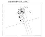
図8に、自走式掃除機1が充電台の近傍に戻ってきたときの充電台への接続動作の説明図を示す。
ここでは、充電台100の赤外線送信部106と、自走式掃除機1の赤外線受信部18とを利用する。
充電台100から、指向性を持った赤外線を送信し、その赤外線を受光できる所定の領域を領域Aとする。この場合、充電台100の近傍にまで戻ってきた自走式掃除機1が、赤外線を受信した場合、所定の領域Aに戻ってきたと判断し、その位置で静止し、その後、互いの接続部(51,101)を接続させるための一連の処理を行うようにしてもよい。
このように、BLE信号を用いた距離測定に加えて、赤外線の受信処理を行うようにすれば、より確実に、充電台への帰還処理を行うことができる。
ここでは、充電台100の赤外線送信部106と、自走式掃除機1の赤外線受信部18とを利用する。
充電台100から、指向性を持った赤外線を送信し、その赤外線を受光できる所定の領域を領域Aとする。この場合、充電台100の近傍にまで戻ってきた自走式掃除機1が、赤外線を受信した場合、所定の領域Aに戻ってきたと判断し、その位置で静止し、その後、互いの接続部(51,101)を接続させるための一連の処理を行うようにしてもよい。
このように、BLE信号を用いた距離測定に加えて、赤外線の受信処理を行うようにすれば、より確実に、充電台への帰還処理を行うことができる。
(第1実施形態の帰還処理のフローチャート)
図9(a),(b)に、この発明の第1実施形態の帰還処理のフローチャートを示す。
図9(a)のステップS1において、ユーザが入力部35を用いて、所定の目標距離42を入力し、目標距離を示す変数ky_xに設定する。あるいは、予め、目標距離42を固定的に変数ky_xに記憶しておいてもよい。
図9(a),(b)に、この発明の第1実施形態の帰還処理のフローチャートを示す。
図9(a)のステップS1において、ユーザが入力部35を用いて、所定の目標距離42を入力し、目標距離を示す変数ky_xに設定する。あるいは、予め、目標距離42を固定的に変数ky_xに記憶しておいてもよい。
ステップS2において、信号通信部14によってBLE信号を受信し、受信したBLE信号を用いて、距離測定部16が自走式掃除機1と充電台100との距離を算出する。この測定距離を、初期位置の距離として、最小測定距離ky_minに記憶させる。
ステップS3において、自走式掃除機1の現在の前方方向に向かって、一定距離だけ前進走行を行う。一定距離としては、特に一意的に限定するものではないが、精度を高くするためには、できるだけ短い距離が好ましく、たとえば、10cm~20cm程度の距離を設定すればよい。
また、一定距離は固定値ではなく、可変としてもよい。たとえば、測定距離が比較的長い場合は、一定距離を長く設定し、充電台に近づいたために測定距離が所定値よりも短くなった場合に、一定距離を短く設定してもよい。
また、一定距離は固定値ではなく、可変としてもよい。たとえば、測定距離が比較的長い場合は、一定距離を長く設定し、充電台に近づいたために測定距離が所定値よりも短くなった場合に、一定距離を短く設定してもよい。
ステップS4において、障害検知部34によって障害物が検知されたか否かを、チェックする。障害物が検知された場合は、ステップS5へ進み、そうでない場合は、ステップS6へ進む。障害物が検出された場合とは、自走式掃除機本体の側面が物体に接触した場合や、超音波センサ15によって前進方向に物体を検出した場合を含む。
ステップS5において、所定の方向転換を行い、ステップS2へ戻る。所定の方向転換は、たとえば、障害物が検知された位置で静止して、障害物を避けることができる程度の角度だけ回転すればよい。
回転動作は、たとえば、30度、60度、90度、180度というように予め設定された角度の他、ランダムな角度で、回転するようにしてもよい。ステップS2へ戻った後は、上記した一連の処理を繰り返す。
回転動作は、たとえば、30度、60度、90度、180度というように予め設定された角度の他、ランダムな角度で、回転するようにしてもよい。ステップS2へ戻った後は、上記した一連の処理を繰り返す。
ただし、ランダムな角度等で回転する場合、超音波センサに15を用いて、その回転後の前方方向に、障害物がないことを確認した後に、その前方方向へ走行することが好ましい。
また、障害物が壁の場合は、ランダムな角度で方向転換してもよいが、壁ぎわまで走行した後、その壁に沿った走行をするようにしてもよい。
また、障害物が壁の場合は、ランダムな角度で方向転換してもよいが、壁ぎわまで走行した後、その壁に沿った走行をするようにしてもよい。
ステップS6において、信号通信部14によって受信したBLE信号を用いて、距離測定部16が、自走式掃除機1と充電台100との距離を算出する。この測定距離は、現在の測定距離を示す変数ky_tmpに記憶させる。
ステップS7において、ky_min<ky_tmpか否かを、チェックする。すなわち、自走式掃除機1がいる現在の位置で測定した現在測定距離ky_tmpが、今までに測定された距離のうち最小の距離(最小測定距離ky_min)よりも大きいか否かを、チェックする。ky_min<ky_tmpの場合はステップS8へ進み、そうでない場合は、ステップS9へ進む。
ステップS8において、進行方向を、充電台から遠ざからない方向に変更するために、現在の位置で、180度の回転動作をする。
ステップS9において、最小測定距離ky_minに、現在測定距離ky_tmpを代入し、最小測定距離を更新する。
ステップS10において、ステップS3と同様に、一定距離だけ、前進させる。
ステップS9において、最小測定距離ky_minに、現在測定距離ky_tmpを代入し、最小測定距離を更新する。
ステップS10において、ステップS3と同様に、一定距離だけ、前進させる。
ステップS11において、ステップS4と同様に、障害物の検出チェックを行う。障害物がある場合は、ステップS12へ進み、ステップS5と同様に、方向転換処理を行い、ステップS2へ戻る。
障害物のない場合は、ステップS13へ進み、ステップS6と同様に、現在測定距離ky_tmpを測定し、記憶する。
障害物のない場合は、ステップS13へ進み、ステップS6と同様に、現在測定距離ky_tmpを測定し、記憶する。
ステップS14において、ステップS7と同様に、ky_min<ky_tmpをチェックし、自走式掃除機1が、前回までの最小測定距離ky_minよりも充電台100に近づいた場合(ky_min≧ky_tmp)、ステップS9へ戻り、ステップS9からS13までの処理を繰り返す。
一方、自走式掃除機1が、一定距離の走行によって、前回までの最小測定距離ky_minよりも充電台100から遠ざかる方向に進行した場合(ky_min<ky_tmp)、ステップS15へ進み、ステップS8と同様に、180度の回転動作を行う。
一方、自走式掃除機1が、一定距離の走行によって、前回までの最小測定距離ky_minよりも充電台100から遠ざかる方向に進行した場合(ky_min<ky_tmp)、ステップS15へ進み、ステップS8と同様に、180度の回転動作を行う。
ステップS16において、ステップS3と同様に一定距離の走行を行い、ステップS17において、ステップS4と同様の障害物検出処理を行う。
障害物がある場合は、ステップS18へ進み、ステップS5と同様に方向転換を行って、ステップS2へ戻る。
一方、障害物がない場合は、図9(b)のステップS19へ進み、現在位置に静止して、左方向に90度回転する。ただし、右方向への90度回転をしてもよい。
ここで、90度回転するのは、すでに、180度回転した方向から現在位置まで進行してきたので、再度180度回転した場合には、すでに通ってきた過去の位置に戻ることになるからである。
したがって、回転角度としては、180度以外の角度を選択すればよいが、その後の進路を明確に設定するために、上記のように、たとえば90度の回転を選択すればよい。このような90度回転をした後は、新たな直線上における走行が行われることになる。
障害物がある場合は、ステップS18へ進み、ステップS5と同様に方向転換を行って、ステップS2へ戻る。
一方、障害物がない場合は、図9(b)のステップS19へ進み、現在位置に静止して、左方向に90度回転する。ただし、右方向への90度回転をしてもよい。
ここで、90度回転するのは、すでに、180度回転した方向から現在位置まで進行してきたので、再度180度回転した場合には、すでに通ってきた過去の位置に戻ることになるからである。
したがって、回転角度としては、180度以外の角度を選択すればよいが、その後の進路を明確に設定するために、上記のように、たとえば90度の回転を選択すればよい。このような90度回転をした後は、新たな直線上における走行が行われることになる。
ステップS20において、現在位置での測定距離を、最小測定距離の仮の初期値(ky_min)として設定記憶する。
ステップS21において、ステップS3と同様に、一定距離だけ前進する。この後、ステップS22からS26までは、ステップS4からS8までと同様の処理を、繰り返し行う。
ステップS21において、ステップS3と同様に、一定距離だけ前進する。この後、ステップS22からS26までは、ステップS4からS8までと同様の処理を、繰り返し行う。
ステップS27において、ステップS9と同様に、現在測定距離ky_tmpを、新しい最小測定距離ky_minに更新した後、ステップS28からS31まで、上記したステップS10からステップS13までの処理と、同様の処理を行う。
ステップS32において、ky_tmp<ky_xをチェックする。
現在測定距離ky_tmpが、目標距離ky_xよりも小さくなった場合は、自走式掃除機1が充電台の所定の近傍にまで戻ったと判断し、帰還処理を終了する。
一方、現在測定距離ky_tmpが、目標距離ky_xよりも大きい場合は、まだ帰還途中であるので、ステップS28に戻り、ステップS28からS31までの処理を繰り返す。
以上の帰還処理を実行すれば、壁に沿った走行などの無駄な走行を減らすことができ、充電台までの帰還処理にかかる時間を短縮することができる。
現在測定距離ky_tmpが、目標距離ky_xよりも小さくなった場合は、自走式掃除機1が充電台の所定の近傍にまで戻ったと判断し、帰還処理を終了する。
一方、現在測定距離ky_tmpが、目標距離ky_xよりも大きい場合は、まだ帰還途中であるので、ステップS28に戻り、ステップS28からS31までの処理を繰り返す。
以上の帰還処理を実行すれば、壁に沿った走行などの無駄な走行を減らすことができ、充電台までの帰還処理にかかる時間を短縮することができる。
<第2実施形態>
図10から図12に、この発明の帰還処理の第2実施形態の説明図を示す。
第2実施形態では、目標対象物である充電台までの距離を測定しながら、自走式電子機器が充電台から遠ざかる方向に移動していると判定された場合に、上記判定をした現在位置で、一定方向の90度の回転動作を行わせ、直線走行と、上記一定方向と同一方向の90度の回転動作とを組み合わせた走行を行うことによって、自走式電子機器を充電台の近傍領域にまで移動させる。
上記一定方向は、左方向および右方向のいずれでもよいが、両方向を混在させるのではなく、予め設定したどちらか一方の方向を用いるものとする。
図10(a)に、自走式掃除機1の初期位置と、充電台100までの初期距離を示す。ここでは、測定された初期距離は、最小測定距離ky_minとして記憶される。図10(a)では、左ややななめ下方向が、自走式掃除機の前進方向とする。
図10から図12に、この発明の帰還処理の第2実施形態の説明図を示す。
第2実施形態では、目標対象物である充電台までの距離を測定しながら、自走式電子機器が充電台から遠ざかる方向に移動していると判定された場合に、上記判定をした現在位置で、一定方向の90度の回転動作を行わせ、直線走行と、上記一定方向と同一方向の90度の回転動作とを組み合わせた走行を行うことによって、自走式電子機器を充電台の近傍領域にまで移動させる。
上記一定方向は、左方向および右方向のいずれでもよいが、両方向を混在させるのではなく、予め設定したどちらか一方の方向を用いるものとする。
図10(a)に、自走式掃除機1の初期位置と、充電台100までの初期距離を示す。ここでは、測定された初期距離は、最小測定距離ky_minとして記憶される。図10(a)では、左ややななめ下方向が、自走式掃除機の前進方向とする。
ここでは、以下のような直線的な走行と、左方向への90度の回転動作とを利用して、自走式掃除機1が、目標距離ky_xよりも充電台に近い位置に帰還するものを示す。
図10(b)において、一定距離だけ前進し、その位置での充電台までの距離を測定し、現在測定距離ky_tmpとして記憶する。
図10(b)において、一定距離だけ前進し、その位置での充電台までの距離を測定し、現在測定距離ky_tmpとして記憶する。
図10(b)において、自走式掃除機1は充電台100から遠ざかる方向に移動したので、図10(c)に示すように、図10(b)の位置で静止して、90度左回転をする。これにより、前進方向は、右下方向となる。
この位置での測定距離を、最小測定距離ky_minとして記憶する。
この位置での測定距離を、最小測定距離ky_minとして記憶する。
図10(d)において、図10(c)の位置からさらに一定距離だけ前進して、その位置での充電台100までの距離を測定し、現在測定距離ky_tmpとして記憶する。
図10(d)の前進走行によって、充電台から遠ざかる方向に移動したので、図11(a)に示すように、図10(d)の現在位置で静止して、90度左回転をする。これにより、右ややななめ上が、前進方向となる。この位置での測定距離を、最小測定距離ky_minとして記憶する。
図10(d)の前進走行によって、充電台から遠ざかる方向に移動したので、図11(a)に示すように、図10(d)の現在位置で静止して、90度左回転をする。これにより、右ややななめ上が、前進方向となる。この位置での測定距離を、最小測定距離ky_minとして記憶する。
図11(b)において、さらに一定距離だけ前進し、その位置での充電台までの距離を測定し、現在測定距離ky_tmpとして記憶する。
図11(b)では、前進した位置でのky_tmpは、ky_minよりも小さくなっているので、自走式掃除機1は、充電台に近づく方向に移動している。そこで、ky_minにky_tmpを代入して、更新する。
図11(b)では、前進した位置でのky_tmpは、ky_minよりも小さくなっているので、自走式掃除機1は、充電台に近づく方向に移動している。そこで、ky_minにky_tmpを代入して、更新する。
図11(c)において、さらに一定距離だけ前進し、同様に、現在測定距離ky_tmpの測定を繰り返し行う。
図11(c)では、充電台までの距離が徐々に短くなっていき、最も右側の位置のky_tmpが、その前回位置での最小測定距離ky_minよりも大きくなっている。これ以上、同方向に前進をし続けると、充電台からますます遠ざかる方向に移動することになる。
そこで、図11(d)に示すように、自走式掃除機1は、図11(c)の最も右側の位置で、90度左回転をする。
これにより、前進方向は、左上方向となる。この位置での測定距離を、最小測定距離ky_minとして記憶する。
図11(c)では、充電台までの距離が徐々に短くなっていき、最も右側の位置のky_tmpが、その前回位置での最小測定距離ky_minよりも大きくなっている。これ以上、同方向に前進をし続けると、充電台からますます遠ざかる方向に移動することになる。
そこで、図11(d)に示すように、自走式掃除機1は、図11(c)の最も右側の位置で、90度左回転をする。
これにより、前進方向は、左上方向となる。この位置での測定距離を、最小測定距離ky_minとして記憶する。
次に、図12に示すように、一定距離毎に前進を繰り返し、現在測定距離ky_tmpが、目標距離ky_xよりも短くなるか否かをチェックする。
図12では、ky_tmp<ky_xとなったので、自走式掃除機1が充電台100まで帰還したと考え、帰還処理を終了する。この後は、上記したように、2つの接続部(51,101)どおしを接触させる動作を行わせる。
図12では、ky_tmp<ky_xとなったので、自走式掃除機1が充電台100まで帰還したと考え、帰還処理を終了する。この後は、上記したように、2つの接続部(51,101)どおしを接触させる動作を行わせる。
以上のように、図10(a)の場合は、直線的な前進走行と、3回の90度の左回転動作とによって、自走式掃除機1は、充電台の近傍にまで戻ってくることができ、壁に沿った走行やランダム走行をすることなく、無駄な走行を防止して、充電台に帰還するまでの時間を短縮することができる。
図10から図12の説明は、最悪の場合の帰還処理を示したものであるが、90度の回転動作を右方向への回転に予め設定していた場合は、2回の右方向回転動作と直線的な前進走行とによって充電台まで帰還することができ、上記よりも短い時間で帰還することができる。
図13に、第2実施形態の帰還処理のフローチャートを示す。
図9のフローチャートと同じ処理には、同一のステップ番号を付与している。
図13において、ステップS1からステップS7までの一連の処理は、図9と同一の処理である。
図9のフローチャートと同じ処理には、同一のステップ番号を付与している。
図13において、ステップS1からステップS7までの一連の処理は、図9と同一の処理である。
ステップS7において、ky_min<ky_tmpとなった場合は、ステップS40に進む。この場合は、図10(b)のように、充電台から遠ざかる方向に前進した場合に対応する。
ステップS40では、現在位置に制した状態で、90度の左回転をする。その後、ステップS2へ戻り、一連の処理を繰り返す。
一方、ky_min≧ky_tmpの場合は、充電台に近づく方向に移動したので、ステップS41へ進む。
ステップS40では、現在位置に制した状態で、90度の左回転をする。その後、ステップS2へ戻り、一連の処理を繰り返す。
一方、ky_min≧ky_tmpの場合は、充電台に近づく方向に移動したので、ステップS41へ進む。
ステップS41では、ステップS32と同様に、ky_tmp<ky_xをチェックする。
ky_tmp<ky_xの場合、自走式掃除機1は、目標とする充電台の近傍にまで戻ってきたと判断し、帰還処理を終了する。
一方、ky_tmp≧ky_xの場合、まだ帰還途中であるので、ステップS2へ戻って、一連の処理を繰り返す。
ky_tmp<ky_xの場合、自走式掃除機1は、目標とする充電台の近傍にまで戻ってきたと判断し、帰還処理を終了する。
一方、ky_tmp≧ky_xの場合、まだ帰還途中であるので、ステップS2へ戻って、一連の処理を繰り返す。
<第3実施形態>
進行方向に障害物がある場合、そのまま直進することができないので、その障害物を回避するように、進行方向を変更する必要がある。そこで、障害検知部34によって障害物を検知した進行方向とは異なる方向(たとえば、90度左方向、90度右方向)への回転動作を行って、さらにその方向への前進走行をしてもよい。
あるいは、180度の回転動作を行ってもよい。また、回転角度は、90度と180度に限るものではなく、他の角度を利用してもよい。
進行方向に障害物がある場合、そのまま直進することができないので、その障害物を回避するように、進行方向を変更する必要がある。そこで、障害検知部34によって障害物を検知した進行方向とは異なる方向(たとえば、90度左方向、90度右方向)への回転動作を行って、さらにその方向への前進走行をしてもよい。
あるいは、180度の回転動作を行ってもよい。また、回転角度は、90度と180度に限るものではなく、他の角度を利用してもよい。
<第4実施形態>
上記実施例では、目標対象物を、固定設置された充電台としたが、固定設置されたものに限る必要はなく、信号通信部を有する移動体であってもよい。この場合、自走式電子機器は、移動体との距離を測定しながら、移動体に追随していくことができる。
上記実施例では、目標対象物を、固定設置された充電台としたが、固定設置されたものに限る必要はなく、信号通信部を有する移動体であってもよい。この場合、自走式電子機器は、移動体との距離を測定しながら、移動体に追随していくことができる。
11 制御部、 12 充電池、 13 電池残量検出部、 14信号通信部、 15 超音波センサ、 16 距離測定部、 17 距離判定部、 18 赤外線受信部、 21 走行制御部、 22 車輪、 31 吸気口、 32 排気口、 33 集塵部、 34 障害検知部、35 入力部、 41 記憶部、 42 目標距離、 43 最小測定距離、 44 現在測定距離、 45 電池情報、 100 充電台、 101 掃除機接続部、 102 信号通信部、 103 制御部、 104 電力供給部、 105 商用電源、 106 赤外線送信部
Claims (6)
- 目標対象物の位置に向かって自動走行する自走式電子機器であって、
車輪の回転を制御して直線走行および回転動作をさせる走行制御部と、
前記目標対象物から送信された無線信号を受信する信号通信部と、
前記受信された無線信号に基づいて、前記目標対象物までの距離を測定する距離測定部と、
制御部とを備え、
自動走行中に前記距離測定部によって測定された複数の測定距離に基づいて、自走式電子機器が前記目標対象物から遠ざかる方向に移動していると判定された場合に、前記制御部が、現在位置で所定の回転動作を行わせた後、前記目標対象物に近づく方向に直線走行と回転動作とを繰り返し行うことによって、前記目標対象物の所定の近傍領域にまで移動させることを特徴とする自走式電子機器。 - 目標対象物の位置に向かって自動走行する自走式電子機器であって、
車輪の回転を制御して直線走行および回転動作をさせる走行制御部と、
前記目標対象物から送信された無線信号を受信する信号通信部と、
前記受信された無線信号に基づいて、前記目標対象物までの距離を測定する距離測定部と、
自動走行中に前記距離測定部によって測定された最新の現在位置での測定距離と、自動走行中の過去の複数の測定距離のうち最小の測定距離とを比較して大小関係を判定する距離判定部と、制御部とを備え、
前記距離判定部が、前記現在位置での測定距離が、前記最小の測定距離よりも大きくなったと判定した場合に、前記制御部が、前記現在位置で所定の回転動作を行わせた後、
前記目標対象物に近づく方向に直線走行と回転動作を繰り返し行うことによって、前記目標対象物の所定の近傍領域にまで移動させることを特徴とする自走式電子機器。 - 目標対象物の位置に向かって自動走行する自走式電子機器であって、
車輪の回転を制御して直線走行および回転動作をさせる走行制御部と、
前記目標対象物から送信された無線信号を受信する信号通信部と、
前記受信された無線信号に基づいて、前記目標対象物までの距離を測定する距離測定部と、
制御部とを備え、
自動走行中に前記距離測定部によって測定された複数の測定距離に基づいて、自走式電子機器が前記目標対象物から遠ざかる方向に移動していると判定された場合に、
前記制御部が、現在位置で180度の回転動作あるいは90度の回転動作を行わせた後、直線走行と、180度の回転動作と、90度の回転動作とを組み合わせた走行を行うことによって、前記目標対象物の所定の近傍領域にまで移動させることを特徴とする自走式電子機器。 - 前記自走式電子機器が前記目標対象物から遠ざかる方向に移動していると判定された場合に、前記制御部が、上記判定をした現在位置で一定方向の90度の回転動作を行わせ、直線走行と、前記一定方向と同一方向の90度の回転動作とを組み合わせた走行を行うことによって、前記目標対象物の所定の近傍領域にまで移動させることを特徴とする請求項1または2のいずれかに記載の自走式電子機器。
- 前記無線信号は、ブルートゥース ローエナジーの規格で定められたBLE信号であり、前記信号通信部が受信したBLE信号の受信強度に基づいて、前記距離測定部が、前記目標対象物までの距離を測定することを特徴とする請求項1から4のいずれかに記載の自走式電子機器。
- 前記目標対象物が移動体であり、前記移動体に追随することを特徴とする請求項1から5のいずれかに記載の自走式電子機器。
Priority Applications (1)
| Application Number | Priority Date | Filing Date | Title |
|---|---|---|---|
| CN201580025569.6A CN106455887A (zh) | 2014-05-23 | 2015-01-20 | 自走式电子机器 |
Applications Claiming Priority (2)
| Application Number | Priority Date | Filing Date | Title |
|---|---|---|---|
| JP2014-107039 | 2014-05-23 | ||
| JP2014107039A JP6393520B2 (ja) | 2014-05-23 | 2014-05-23 | 自走式電子機器 |
Publications (1)
| Publication Number | Publication Date |
|---|---|
| WO2015178044A1 true WO2015178044A1 (ja) | 2015-11-26 |
Family
ID=54553723
Family Applications (1)
| Application Number | Title | Priority Date | Filing Date |
|---|---|---|---|
| PCT/JP2015/051374 Ceased WO2015178044A1 (ja) | 2014-05-23 | 2015-01-20 | 自走式電子機器 |
Country Status (3)
| Country | Link |
|---|---|
| JP (1) | JP6393520B2 (ja) |
| CN (1) | CN106455887A (ja) |
| WO (1) | WO2015178044A1 (ja) |
Cited By (1)
| Publication number | Priority date | Publication date | Assignee | Title |
|---|---|---|---|---|
| US20170364087A1 (en) * | 2014-09-30 | 2017-12-21 | Ecovacs Robotics Co., Ltd. | Self-Propelled Surface-Traveling Robot System and Method for Returning to Primary Charging Base |
Families Citing this family (7)
| Publication number | Priority date | Publication date | Assignee | Title |
|---|---|---|---|---|
| WO2017130649A1 (ja) * | 2016-01-26 | 2017-08-03 | インターマン株式会社 | 自律型ロボット |
| WO2018003265A1 (ja) * | 2016-06-28 | 2018-01-04 | パナソニックIpマネジメント株式会社 | 自走清掃装置、自走清掃装置の制御方法、およびプログラム |
| CN108198269A (zh) * | 2018-01-29 | 2018-06-22 | 石化盈科信息技术有限责任公司 | 一种巡检信息实时集成展示方法及系统 |
| WO2020153442A1 (ja) * | 2019-01-25 | 2020-07-30 | シャープ株式会社 | 自走式電子機器、ドッキングステーション及びドッキング方法 |
| JP7342664B2 (ja) * | 2019-11-29 | 2023-09-12 | 新東工業株式会社 | ロボット、制御方法、およびプログラム |
| CN110960149A (zh) * | 2019-12-17 | 2020-04-07 | 江苏美的清洁电器股份有限公司 | 扫地机回充方法、装置、扫地机及系统 |
| CN118408532A (zh) * | 2024-04-17 | 2024-07-30 | 广东东软学院 | 基于激光SLAM、GPS和WiFi的定位导航方法 |
Citations (3)
| Publication number | Priority date | Publication date | Assignee | Title |
|---|---|---|---|---|
| JPH10502274A (ja) * | 1994-07-04 | 1998-03-03 | ソーラー アンド ロボティクス エス・アー | 床清掃用自動機械及び装置 |
| JP2007272301A (ja) * | 2006-03-30 | 2007-10-18 | Toshiba Corp | ドッキングシステム |
| JP2008181177A (ja) * | 2007-01-23 | 2008-08-07 | Matsushita Electric Ind Co Ltd | 充電池搭載移動体の充電装置 |
Family Cites Families (14)
| Publication number | Priority date | Publication date | Assignee | Title |
|---|---|---|---|---|
| JP3560950B2 (ja) * | 2001-12-07 | 2004-09-02 | エヌ・ティ・ティ・アドバンステクノロジ株式会社 | 自走制御装置及びその制御方法、自走装置 |
| KR100492590B1 (ko) * | 2003-03-14 | 2005-06-03 | 엘지전자 주식회사 | 로봇의 자동충전 시스템 및 복귀방법 |
| KR100656701B1 (ko) * | 2004-10-27 | 2006-12-13 | 삼성광주전자 주식회사 | 로봇청소기 시스템 및 외부충전장치 복귀 방법 |
| KR100696134B1 (ko) * | 2005-04-25 | 2007-03-22 | 엘지전자 주식회사 | 이동로봇의 위치 산출 시스템과 그를 이용한 충전대 복귀시스템 및 그 방법 |
| KR100645381B1 (ko) * | 2005-08-31 | 2006-11-14 | 삼성광주전자 주식회사 | 로봇청소기의 외부충전 복귀장치 및 복귀방법 |
| JP2007101492A (ja) * | 2005-10-07 | 2007-04-19 | Sharp Corp | 移動ロボットの距離および位置検出装置 |
| CN100999078A (zh) * | 2006-01-09 | 2007-07-18 | 田角峰 | 一种机器人自动充电方法及其自动充电装置 |
| CN101648377A (zh) * | 2008-08-11 | 2010-02-17 | 悠进机器人股份公司 | 自动充电式自律移动机器人装置及其自动充电方法 |
| CN101524257B (zh) * | 2009-03-31 | 2011-06-15 | 杭州五星电子有限公司 | 智能吸尘器的自动充电实现方法 |
| CN201993643U (zh) * | 2010-10-11 | 2011-09-28 | 洋通工业股份有限公司 | 使自走吸尘器向充电座移动的导引装置 |
| JP2013070571A (ja) * | 2011-09-26 | 2013-04-18 | Minebea Co Ltd | 自走電子装置 |
| JP2013146302A (ja) * | 2012-01-17 | 2013-08-01 | Sharp Corp | 自走式電子機器 |
| CN103251355A (zh) * | 2012-02-16 | 2013-08-21 | 恩斯迈电子(深圳)有限公司 | 扫地机器人与充电系统 |
| JP2014018562A (ja) * | 2012-07-23 | 2014-02-03 | Sharp Corp | 自走式電子機器および自走式電子機器の充電台への帰還方法 |
-
2014
- 2014-05-23 JP JP2014107039A patent/JP6393520B2/ja not_active Expired - Fee Related
-
2015
- 2015-01-20 WO PCT/JP2015/051374 patent/WO2015178044A1/ja not_active Ceased
- 2015-01-20 CN CN201580025569.6A patent/CN106455887A/zh active Pending
Patent Citations (3)
| Publication number | Priority date | Publication date | Assignee | Title |
|---|---|---|---|---|
| JPH10502274A (ja) * | 1994-07-04 | 1998-03-03 | ソーラー アンド ロボティクス エス・アー | 床清掃用自動機械及び装置 |
| JP2007272301A (ja) * | 2006-03-30 | 2007-10-18 | Toshiba Corp | ドッキングシステム |
| JP2008181177A (ja) * | 2007-01-23 | 2008-08-07 | Matsushita Electric Ind Co Ltd | 充電池搭載移動体の充電装置 |
Cited By (2)
| Publication number | Priority date | Publication date | Assignee | Title |
|---|---|---|---|---|
| US20170364087A1 (en) * | 2014-09-30 | 2017-12-21 | Ecovacs Robotics Co., Ltd. | Self-Propelled Surface-Traveling Robot System and Method for Returning to Primary Charging Base |
| US10940767B2 (en) * | 2014-09-30 | 2021-03-09 | Ecovacs Robotics Co., Ltd. | Self-propelled surface-traveling robot system and method for returning to primary charging station |
Also Published As
| Publication number | Publication date |
|---|---|
| JP2015221148A (ja) | 2015-12-10 |
| JP6393520B2 (ja) | 2018-09-19 |
| CN106455887A (zh) | 2017-02-22 |
Similar Documents
| Publication | Publication Date | Title |
|---|---|---|
| JP6393520B2 (ja) | 自走式電子機器 | |
| US9340116B2 (en) | Self-propelled electronic device | |
| JP6289268B2 (ja) | 自走式電子機器 | |
| JP6397663B2 (ja) | 自走式電子機器 | |
| US10213080B2 (en) | Autonomous traveling body device | |
| JP5396577B2 (ja) | 動作システム | |
| CN106264358B (zh) | 一种智能回充系统的智能回充方法 | |
| CN111602097B (zh) | 自移动设备及其控制方法 | |
| US10542858B2 (en) | Self-propelled electronic device and travel method for self-propelled electronic device | |
| KR20180079962A (ko) | 로봇 청소기 및 그 제어 방법 | |
| JP6397278B2 (ja) | 自走式掃除機 | |
| JP6422703B2 (ja) | 自律走行体装置 | |
| JP2013169224A (ja) | 自走式掃除機 | |
| JP6378986B2 (ja) | 自走式電子機器およびその帰還方法 | |
| JP2017063968A (ja) | 走行体装置 | |
| JP2016021181A (ja) | 自走式電子機器 | |
| JP6942102B2 (ja) | 自走式掃除機 | |
| JP7089452B2 (ja) | 自走式掃除機 | |
| JP2019208545A (ja) | 床面を移動する移動体 | |
| JP2016033746A (ja) | 自走式電子機器 | |
| JPWO2018003265A1 (ja) | 自走清掃装置、自走清掃装置の制御方法、およびプログラム | |
| JP6494952B2 (ja) | 自律走行体 | |
| KR20070096689A (ko) | 이동로봇 및 이동로봇의 주행 방법 |
Legal Events
| Date | Code | Title | Description |
|---|---|---|---|
| 121 | Ep: the epo has been informed by wipo that ep was designated in this application |
Ref document number: 15796496 Country of ref document: EP Kind code of ref document: A1 |
|
| NENP | Non-entry into the national phase |
Ref country code: DE |
|
| 122 | Ep: pct application non-entry in european phase |
Ref document number: 15796496 Country of ref document: EP Kind code of ref document: A1 |