WO2015174352A1 - Dispositif de traitement de supports et cassette de stockage de supports - Google Patents
Dispositif de traitement de supports et cassette de stockage de supports Download PDFInfo
- Publication number
- WO2015174352A1 WO2015174352A1 PCT/JP2015/063382 JP2015063382W WO2015174352A1 WO 2015174352 A1 WO2015174352 A1 WO 2015174352A1 JP 2015063382 W JP2015063382 W JP 2015063382W WO 2015174352 A1 WO2015174352 A1 WO 2015174352A1
- Authority
- WO
- WIPO (PCT)
- Prior art keywords
- slot
- storage cassette
- cassette
- side guide
- loading
- Prior art date
Links
Images


Classifications
-
- B—PERFORMING OPERATIONS; TRANSPORTING
- B65—CONVEYING; PACKING; STORING; HANDLING THIN OR FILAMENTARY MATERIAL
- B65H—HANDLING THIN OR FILAMENTARY MATERIAL, e.g. SHEETS, WEBS, CABLES
- B65H1/00—Supports or magazines for piles from which articles are to be separated
- B65H1/26—Supports or magazines for piles from which articles are to be separated with auxiliary supports to facilitate introduction or renewal of the pile
-
- B—PERFORMING OPERATIONS; TRANSPORTING
- B65—CONVEYING; PACKING; STORING; HANDLING THIN OR FILAMENTARY MATERIAL
- B65H—HANDLING THIN OR FILAMENTARY MATERIAL, e.g. SHEETS, WEBS, CABLES
- B65H83/00—Combinations of piling and depiling operations, e.g. performed simultaneously, of interest apart from the single operation of piling or depiling as such
- B65H83/02—Combinations of piling and depiling operations, e.g. performed simultaneously, of interest apart from the single operation of piling or depiling as such performed on the same pile or stack
-
- G—PHYSICS
- G07—CHECKING-DEVICES
- G07D—HANDLING OF COINS OR VALUABLE PAPERS, e.g. TESTING, SORTING BY DENOMINATIONS, COUNTING, DISPENSING, CHANGING OR DEPOSITING
- G07D9/00—Counting coins; Handling of coins not provided for in the other groups of this subclass
Definitions
- the disclosed technology relates to a medium processing apparatus and a medium storage cassette, and is a medium processing apparatus and a medium storage cassette suitable for application to, for example, an automatic teller machine that handles banknotes as a medium.
- a banknote deposit / withdrawal port that exchanges banknotes with customers
- a discrimination section that discriminates the denomination, authenticity, and correctness of inserted banknotes
- a temporary storage section that temporarily holds inserted banknotes
- an automatic teller machine having a storage cassette for storing banknotes for each denomination.
- This automatic teller machine in a deposit transaction, when a customer inserts a banknote into a banknote deposit / withdrawal port, the inserted banknote is discriminated by a discrimination unit, and a banknote discriminated from a normal banknote is held in a temporary holding unit, The banknotes identified as not to be traded are returned to the banknote deposit / withdrawal port and returned to the customer. Subsequently, when the deposit amount is confirmed by the customer's operation instruction, the automatic teller machine re-discriminates the denomination of the banknote held in the temporary holding unit by the discrimination unit and stores it in the storage cassette corresponding to the denomination. .
- the main body is provided with a cassette loading section having a plurality of slots along the vertical direction, and each slot of the cassette loading section
- an automatic teller machine in which storage cassettes are configured to be detachable one by one.
- a portion of the side surface of the slot is relatively low, for example, up to about half of that when a normal storage cassette is loaded, so that the height at which the storage cassette should be lifted is kept low, and cash that improves workability
- An automatic teller machine has also been proposed (see, for example, JP 2011-118699 A (FIG. 2)).
- an automatic teller machine has been proposed in which a small storage cassette having a height that is approximately half that of a normal storage cassette is prepared, and the small storage cassette is loaded in two layers in one slot. Yes.
- each slot can be loaded with one normal storage cassette or two small storage cassettes, so depending on the number of types of banknotes to be handled and the number of banknotes to be stored.
- the configuration can be changed flexibly.
- an automatic teller machine incorporates a mechanism for collecting and separating banknotes in each storage cassette, a sensor for detecting the amount of banknotes stored, and the like. Therefore, each slot of the storage cassette and the cassette loading unit is provided with a connector having a plurality of minute terminals for electrical connection to each other when the storage cassette is loaded in the cassette loading unit. .
- the upper storage cassette in the case where two small storage cassettes are stacked has a lower side portion due to the lower side surface. Only the upper part is not supported. For this reason, even if a small storage cassette is loaded in the correct position in the automatic teller machine, if a vibration or impact is applied from the outside, the storage cassette moves or rotates slightly in the slot. As a result, there is a problem that the electrical connection is cut by releasing the mating of the connectors.
- the disclosed technology proposes a medium processing apparatus and a medium storage cassette that can achieve both a high level of ease of loading and unloading a cassette with respect to a slot and maintaining positional accuracy in a loaded state.
- a storage cassette that stores a medium therein and a storage cassette are loaded along the loading direction, and two or more storage cassettes are loaded first.
- a media processing apparatus comprising a slot in which a post-load storage cassette is stacked and loaded after the load storage cassette, wherein the slot is provided in a part of a side wall surrounding a post-loading position in which the post-load storage cassette is loaded An opening that allows entry and exit of the post-loading storage cassette in a crossing direction that intersects the loading direction, and is outside a preloading passage range that is a range through which the preloading storage cassette passes.
- a first slot side guide which is provided closer to the preload storage cassette than the center of the rear load storage cassette and guides the rear load storage cassette to a predetermined postload position along the loading direction. And a second slot that is located outside the first loading passage range and opposite the first slot side guide across the first loading passage range and guides the rear loading storage cassette to the rear loading position along the loading direction.
- the post-loading and storing cassette is loaded into the slot, and the first cassette-side guide that contacts the first slot-side guide and sequentially regulates the loading posture of the post-loading and storing cassette when being loaded into the slot.
- the first cassette side guide comes into contact with the first slot side guide
- the second cassette side guide is in contact with the second slot side guide and the loading posture of the post-loading storage cassette is sequentially regulated.
- the opening side of the post-load storage cassette is not supported by the slot, but the third slot side guide is close to the third cassette side guide or Therefore, even if vibration is applied, rotation around the center of gravity can be prevented, and the fitting between the cassette side connector and the slot side connector can be maintained.
- the medium storage cassette of the disclosed technology is a medium storage cassette that stores a medium therein and is loaded after another medium storage cassette is loaded along a loading direction in a predetermined slot,
- the medium storage cassette is loaded in contact with a first slot side guide provided outside the passing range which is a range through which another medium storing cassette passes when loaded in the slot.
- a first cassette-side guide whose posture is sequentially regulated and a first cassette-side guide that is provided on the opposite side of the first cassette-side guide across the center of the medium storage cassette and is loaded into the slot.
- the medium comes into contact with the second slot side guide provided on the opposite side of the first slot side guide across the passage range in the slot.
- a second cassette side guide in which the loading posture of the delivery cassette is sequentially regulated, and a cassette side connector electrically connected to a slot side connector provided in the slot when guided to a predetermined position in the slot;
- the cassette side connector centered on the center of gravity of the medium storage cassette is brought into contact with or in contact with the third slot side guide provided in the slot.
- a third cassette side guide for suppressing rotation in a direction away from the third cassette.
- the opening side of the medium storage cassette is not supported by the slot, but the third slot side guide is brought close to or in contact with the third cassette side guide. Therefore, even if vibration is applied, rotation around the center of gravity can be prevented, and the fitting between the cassette side connector and the slot side connector can be maintained.
- the disclosed technique can realize a medium processing apparatus and a medium storage cassette that can achieve both a high level of compatibility between the ease of loading and unloading the cassette with respect to the slot and the maintenance of the positional accuracy in the loaded state.
- the automatic teller machine 1 includes a box-shaped housing 2.
- the automatic teller machine 1 is installed in a financial institution, for example, and performs transactions related to cash such as a deposit transaction and a withdrawal transaction with a customer.
- the housing 2 is provided with a customer service section 3 at a location where it is easy to insert bills or operate with a touch panel while the customer faces the front side.
- the customer service unit 3 includes a card entry / exit 4, a deposit / withdrawal port 5, an operation display unit 6, a numeric keypad 7, and a receipt issuance port 8. And accept operation instructions.
- Card entry / exit 4 is a portion where various cards such as cash cards are inserted or ejected.
- a card processing unit for reading account numbers and the like magnetically recorded on various cards is provided inside the housing of the card slot 4.
- the deposit / withdrawal port 5 is a portion where banknotes to be deposited by the customer are input and banknotes to be dispensed to the customer are discharged.
- the deposit / withdrawal port 5 is opened or closed by driving a shutter.
- the operation display unit 6 is integrated with an LCD (Liquid Crystal Display) for displaying an operation screen at the time of transaction and a touch panel for selecting a transaction type, inputting a personal identification number, transaction amount, and the like.
- the numeric keypad 7 is a physical key that accepts input of numbers such as “0” to “9”, and is used when an input operation such as a password or transaction amount is performed.
- the receipt issuing port 8 is a part that issues a receipt on which transaction details are printed at the end of transaction processing. A receipt processing unit for printing transaction contents and the like on the receipt is provided inside the housing from the receipt issuing port 8.
- the side of the automated teller machine 1 facing the customer is the front side, the opposite is the rear side, the left and right are the left side and the right side as viewed from the customer facing the front side, and the upper side and the lower side. Is defined and explained.
- the housing 2 is configured such that a front door that covers the front surface and a rear door that covers the rear surface can be opened and closed. That is, the housing
- the housing 2 is easy to work on each part by opening the front door etc. as necessary when a financial institution staff or worker performs maintenance work or banknote replenishment / collection work. Can be done.
- a main control unit 9 that performs overall control of the entire automatic teller machine 1, a banknote depositing and dispensing machine 10 that performs various processes related to banknotes, and the like.
- the main control unit 9 includes a CPU (Central Processing Unit) and reads and executes a predetermined program from a ROM (Read Only Memory), a flash memory, or the like, thereby performing various processes such as a deposit transaction and a withdrawal transaction. .
- the main control unit 9 includes a storage unit 9A such as a RAM (Random Access Memory), a hard disk drive, a flash memory, and the like, and stores various information in the storage unit 9A.
- the bill depositing / dispensing machine 10 is provided with various mechanisms related to bill depositing and dispensing processes inside the bill depositing / dispensing machine housing 11. Each part of the bill depositing / dispensing machine 10 is controlled by the bill control unit 12.
- the banknote control unit 12 includes a CPU, reads out and executes a predetermined program from a ROM, a flash memory, or the like, and cooperates with other control units such as the main control unit 9 to Control various processes related to banknotes, such as the deposit process and withdrawal process.
- the banknote control part 12 has memory
- the banknote control unit 12 receives a predetermined operation input via the operation display unit 6 in cooperation with the main control unit 9 and the like.
- the shutter of the deposit / withdrawal port 5 (FIG. 1) is opened, and a bill is inserted into the deposit / withdrawal unit 13.
- the deposit / withdrawal unit 13 closes the shutter of the deposit / withdrawal port 5 and then removes the banknotes one by one and delivers them to the transport unit 14.
- the conveyance part 14 can convey a banknote to each part in the banknote depositing / withdrawing machine 10, advances the banknote passed along the short side direction, and conveys it to the discrimination part 15.
- the discrimination unit 15 discriminates the denomination and authenticity of the banknote and the degree of damage while conveying the banknote, and notifies the banknote control unit 12 of the discrimination result.
- the banknote control unit 12 determines the transport destination of the banknote based on the acquired discrimination result.
- the transport unit 14 temporarily holds the banknote (correct bill) identified as normal in the discrimination unit 15 by transporting it to the temporary storage unit 16, and the banknote identified as not to be traded (so-called so-called).
- a non-paid ticket or a fake ticket) is conveyed to the deposit / withdrawal unit 13 and returned to the customer.
- the banknote control unit 12 allows the customer to confirm the deposit amount via the operation display unit 6 (FIG. 1), conveys the banknotes held in the temporary storage unit 16 to the discrimination unit 15, and denominations and damages thereof. Differentiate the degree, etc., and obtain the result of the discrimination. And the banknote control part 12 will convey this to the rejection store
- the storage cassette 19 accumulates and stores the delivered banknotes inside.
- the banknote control unit 12 is linked with the main control unit 9 and the like via the operation display unit 6 (FIG. 1). After accepting the operation input, banknotes corresponding to the amount to be withdrawn are drawn out from the storage cassette 19. Subsequently, the banknote control unit 12 conveys the banknote to the discrimination unit 15 by the lower conveyance unit 18 and the conveyance unit 14, and then conveys the bill to the deposit / withdrawal unit 13, and the shutter of the deposit / withdrawal port 5 (FIG. 1). Open and let the customer pick up this bill.
- the banknotes deposited by the customer are sorted by the lower transport unit 18 and stored in the storage cassette 19, and the banknotes are fed out from the storage cassette 19 to be withdrawn to the customer.
- the lower conveyance unit 18 and the storage cassette 19 are incorporated in a lower unit 21 that occupies the lower side of the banknote depositing and dispensing machine 10.
- the lower unit 21 moves in the front-rear direction via a slide rail 22 that expands and contracts in the front-rear direction with respect to the lower case 11 ⁇ / b> A formed in the lower part of the bill depositing / dispensing machine case 11. It is attached as possible. Therefore, when the lower unit 21 is moved rearward from the state housed in the lower housing 11A (FIG. 2), the lower unit 21 is pulled out from the lower housing 11A (FIG. 3). When it is moved, it returns to the stored state (FIG. 2).
- the lower unit 21 is formed in a rectangular parallelepiped shape that is long in the front-rear direction as a whole, and is roughly composed of a lower loading portion 25 and an upper lid portion 26.
- the loading unit 25 has a space for loading the storage cassette 19 (FIG. 2) therein by closing the front and rear side surfaces, the right side surface, the lower side and the bottom side of the left side, and opening the upper side of the top and left sides. An opening is formed on the upper side surface to communicate the internal space with the outside.
- the loading portion 25 has five slots 28 arranged in the front-rear direction.
- Each slot 28 is formed in a rectangular parallelepiped shape that is elongated in the vertical direction as the loading direction, and can accommodate the storage cassette 19.
- a relatively large storage cassette 19A there are three types of storage cassettes 19 that can be loaded into the slots 28: a relatively large storage cassette 19A, a relatively small lower stage small storage cassette 19B, and a relatively small upper stage small storage cassette 19C.
- the lower small storage cassette 19B as the pre-loading storage cassette and the upper small storage cassette 19C as the post-loading storage cassette have substantially the same length in the front-rear direction and the left-right direction compared to the large storage cassette 19A.
- the vertical length is about half. Therefore, each slot 28 can be loaded with one large storage cassette 19A, or can be loaded with two storage cassettes 19 with the upper small storage cassette 19C overlaid on the lower small storage cassette 19B.
- the lid part 26 (FIG. 4A) is formed in a thin rectangular parallelepiped shape as a whole, and the lower transport part 18 (FIG. 2) is incorporated therein. Further, the lid portion 26 has a plurality of delivery ports 26 ⁇ / b> A for delivering banknotes to and from each storage cassette 19 on the lower surface side (hereinafter also referred to as a cassette facing surface) facing the storage cassette 19. Yes. Short projections 26AP for positioning with the storage cassette 19 are provided in the vicinity of both ends in the longitudinal direction of each delivery port 26A.
- the lid portion 26 is attached to the loading portion 25 via a hinge 27 so as to be rotatable. That is, the lid 26 rotates around the hinge 27 so that the cassette-facing surface faces downward as shown in FIG. 2 and closes the opening of the loading unit 25, or as shown in FIG. 4A. As described above, it is possible to turn about 90 degrees from the closed state and shift to an open state (details will be described later) in which the cassette facing surface is directed leftward and the opening is opened.
- the loading portion 25 divides a rectangular parallelepiped space surrounded by the bottom portion 31, the right side portion 32, the left side portion 33, the front side plate 34 and the rear side plate 35 in the front-rear direction.
- the partition plates 36 By partitioning with four partition plates 36 arranged in this manner, five slots 28 elongated in the vertical direction are formed.
- a lower slot side connector 37 is provided on the lower end of each slot 28, that is, on the upper surface side of the bottom 31.
- the lower slot side connector 37 is provided with a plurality of connection terminals standing upward to supply electric power and transmit various electric signals.
- the right side portion 32 is formed in a plate shape having a thickness in the left-right direction as the intersecting direction.
- the length of the right side portion 32 in the vertical direction is relatively long, and is substantially equal to the length of the large storage cassette 19A in the vertical direction.
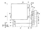
- the right side portion 32 is formed with a step by turning a part of the inner side in the upper half range. Therefore, as shown in FIGS. 6A to 6C, the slot 28 has a shape in which the upper half protrudes to the right as compared with the lower half.
- an upper slot side connector 38 is provided for each slot 28 on the upper surface of the step portion in the right side portion 32.
- the upper slot connector 38 is provided with a plurality of connecting terminals for supplying electric power and transmitting various electric signals upward.
- a right guide body 39 is provided on the boundary portion between the slots 28 on the inner upper side of the right side portion 32, that is, on the upper right side of the partition plate 36, on the side opposite to the opening 33H.
- the right guide body 39 has an enlarged perspective view shown in FIG. 8A and a three-side view shown in FIG. 8B. As shown in FIG. Is formed.
- the right guide body 39 is formed symmetrically with respect to the front-rear direction. For this reason, below, it demonstrates centering on the front side and the description about a rear side is abbreviate
- the right guide body 39 is configured around a thin plate-like substrate 41 in the front-rear direction.
- a lower groove portion 42 extending in the vertical direction is formed in the vicinity of the lower end, and an upper groove portion 46 extending in the vertical direction is formed in the vicinity of the upper end.
- the bottom surfaces of the lower groove portion 42 and the upper groove portion 46 are formed in a planar shape, and are part of a plane that continues from the surface of the substrate 41.
- the lower groove portion 42 has a right side wall portion 43 on the right side (that is, the side attached to the right side portion 32) extending to the upper end, while the left side (that is, the slot 28 side) is in the range of about 1/3 to 1/4 from the lower side. Only the lower left side wall 44 is formed, and the upper part thereof is opened leftward. Further, the lower end of the lower groove portion 42 is closed by a lower stopper 45.
- the upper groove portion 46 is formed with a right side wall portion 43 continuing from the lower groove portion 42 on the right side, and on the left side, the upper left side wall portion 47 similar to the left lower side wall portion 44 in a range of about 3 to 1 ⁇ 4 from the upper side. Is formed. Further, an upper stopper 48 is formed at the lower end of the upper left side wall 47 so as to close the gap with the right side wall 43. The upper stopper 48 is inclined with respect to the horizontal direction so that the right side is lower than the left side.
- the upper groove portion 46 is open on the upper side, like the lower groove portion 42.
- the substrate 41 and the right side wall 43 are exposed only in the range of the left gap 49 formed between the lower left side wall 44 and the upper left side wall 47. .
- the upper left portion of the substrate 41 that is, a part of the surface continuing from the bottom surface of the lower groove portion 42 and the upper portion of the lower left side wall portion 44 has a lower left upper end through the bottom surface of the upper groove portion 46, and the right direction And the inclined surface 41A inclined so that thickness may be increased as it goes below is formed.
- the upper left side of the substrate 41, the upper left side of the right side wall 43, the upper left side of the lower left side wall 44 and the upper left side of the upper left side wall 47 are each cut off in the vicinity of the ridge portion, so-called “chamfered” shape. It is.
- a plurality of right guide bodies 39 are arranged at the boundary between the slots 28, that is, arranged at equal intervals in the front-rear direction on the inner upper stage of the right side portion 32 (FIGS. 5, 7A and 7B). For this reason, for example, when a rear portion of a right guide body 39 and a front portion of a right guide body 39 adjacent to the rear of the right guide body 39 are compared, they are symmetric with respect to the front-rear direction.
- the groove 42 and the upper groove 46 are opposed to each other. Further, when paying attention to each substrate 41, the inclined surface 41A provided on the upper side of the lower left side wall portion 44 is formed so that the interval between the inclined surface 41A increases toward the left side and toward the upper side. Yes.
- the left side portion 33 (FIGS. 5 and 6A to 6C) is formed in a plate shape having a slight thickness in the left-right direction.
- the vertical length of the left side portion 33 is relatively short, slightly longer than the vertical length of the lower small storage cassette 19B, that is, sufficiently shorter than the vertical length of the large storage cassette 19A.
- the upper end of the left side portion 33 is higher than the step portion formed in the right side portion 32 and higher than the upper end of the upper slot side connector 38.
- an opening portion 33H is formed which communicates the inside of the slot 28 with the external space on the left side thereof.
- the height of the opening 33H is lower than the height of the upper small storage cassette 19C (details will be described later).
- the left side portion 33 is formed with a step by turning a part of the inner side in a short range on the upper side.
- the height from the lower end to the step is about the same as the vertical length of the lower small storage cassette 19B.
- the width in the left-right direction on the upper surface of the step is sufficiently narrower than the width in the left-right direction on the upper surface of the step in the right side portion 32 (FIGS. 6A to 6C).
- a left guide body 40 is provided at approximately the center in the front-rear direction of each slot 28 on the inner upper stage of the left side 33.
- the left guide body 40 has a groove portion 52 extending in the vertical direction on the right side surface of the substrate 51 formed as a thin plate in the left-right direction as a whole.
- Both the front side wall 53 and the rear side wall 54 sandwiching the groove 52 from the front and rear are extended to the vicinity of the upper end of the substrate 51. Further, the lower end of the groove 52 is closed by a stopper 55.
- the right front side and the upper right side of the front side wall portion 53 and the right rear side and the upper right side of the rear side wall portion 54 are each scraped off in the vicinity of the ridge portion, and so-called “chamfering” is performed. Further, the upper right rear side of the front side wall portion 53 and the upper right front side of the rear side wall portion 54 are scraped off in the vicinity of the apex portion, and are similarly “chamfered”.
- the thickness in the left-right direction of the left guide body 40 is substantially equal to the width in the left-right direction of the stepped portion in the left side portion 33. For this reason, when the left guide body 40 is attached to the upper inner side of the left side portion 33, the right side surface thereof is the right side surface of the lower side portion of the left side portion 33, as shown in FIGS. 6A to 6C and 7B. Can be almost aligned.
- the front side plate 34, the rear side plate 35, and the partition plate 36 are all formed in a rectangular thin plate shape that is thin in the front-rear direction and long in the vertical direction.
- the length in the vertical direction of the front side plate 34 and the rear side plate 35 is approximately the same as that of the right side portion 32.
- the vertical length of the partition plate 36 is approximately the same as that of the left side portion 33, and is slightly longer than the vertical length of the lower small storage cassette 19B.
- each slot 28 of the loading unit 25 is relatively high only on the right side, and is substantially the same as that of the large storage cassette 19A. A little higher than that.
- the loading portion 25 forms the opening 33H above the left side plate 33, and above the center of each slot 28, the lower groove portion 42 and the upper groove portion 46 formed in the right guide body 39 before and after the right side. Are arranged so as to face each other and the groove 52 formed in the left guide body 40 on the left side is directed to the right.
- Each of the storage cassettes 19 has a separation / stacking function for collecting and storing banknotes carried into the interior and separating and feeding the stacked banknotes one by one.
- the large storage cassette 19 ⁇ / b> A has a rectangular parallelepiped shape that is long in the vertical direction as a whole, and stores bills inside the housing 60.
- a handle 61 is provided on the top plate portion 60A of the large storage cassette 19A.
- the handle 61 includes a gripping part 61A, a support part 61B, and a rotating part 61C.
- the gripping portion 61 ⁇ / b> A is configured in a rod shape whose longitudinal direction is the left-right direction, and has a length substantially equal to the length of the housing 60 in the left-right direction.
- rod-like support portions 61B are respectively extended toward the left and right ends of the grip portion 61A. That is, the handle 61 is formed in a substantially U shape when viewed from the front upper side.
- columnar rotating portions 61C having a central axis in the left-right direction are erected inward in the left-right direction.
- a storage portion 60AC in which portions corresponding to the gripping portion 61A and the support portion 61B are one step lower than the surroundings is formed.
- shaft holes 60AH which are round holes slightly larger than the rotating portion 61C, are bored in the left and right sides of the left and right side surfaces of the storage portion 60AC in the left-right direction. .
- the rotation part 61C of the handle 61 is inserted through the shaft hole 60AH.
- the handle 61 can freely rotate with respect to the top plate portion 60A with the rotation portion 61C as the rotation center. That is, the handle 61 is rotated so that the support portion 61B is laid and the grip portion 61A is embedded in the storage portion 60AC of the top plate portion 60A as shown by the solid line in FIG. 10A (hereinafter referred to as a storage state). ), Or as shown by a broken line in FIG. 10A, the support portion 61B is substantially upright and the grip portion 61A is slightly separated from the top plate portion 60A at the approximate center in the front-rear direction (hereinafter referred to as a grip state). Transition is possible.
- the handle 61 is gripped by a staff member of a financial institution to easily move the entire large storage cassette 19A, for example, to be easily loaded into the slot 28 (FIGS. 4A and 4B). It can be easily removed from the slot 28.
- the position of the shaft hole 60AH is adjusted so that a straight line VL1 (FIG. 10B) that virtually connects the centers of the shaft holes 60AH passes directly above the center of gravity of the large storage cassette 19A.
- VL1 FIG. 10B
- the large storage cassette 19A can adjust the vertical direction of the housing 60 to be substantially vertical when the handle 61 in the gripping state is gripped.
- the outer dimensions in the front-rear direction and the left-right direction in the housing 60 are slightly shorter than the inner dimensions in the front-rear direction and the left-right direction in the slot 28 (FIG. 5), respectively. For this reason, when the large storage cassette 19A is loaded in the slot 28, it is almost positioned at a predetermined loading position.
- the top plate 60A is provided with a delivery port 62 at a position near the rear end.
- the delivery port 62 is a long hole elongated in the left-right direction, and is inserted toward the inside or outside of the housing 60 with the short side direction of the banknote as the traveling direction, that is, with the paper face directed in the front-rear direction. ing.
- the delivery port 62 has, for example, a length of 200 [mm] in the left-right direction and a length of 5 [mm] in the front-rear direction. ]. Further, in the vicinity of the left and right ends on the front side of the delivery port 62, holes 62Q for aligning the horizontal position of the lid 26 (FIGS. 4A and 4B) with respect to the delivery port 26A are formed.
- a rectangular parallelepiped storage space 60S for storing banknotes is formed.
- a separation and stacking unit 65 configured by a guide for guiding bills, a plurality of rotatable rollers, and the like.
- the separation and stacking unit 65 discharges the banknotes between the storage space 60S and the delivery port 62 and discharges them into the storage space 60S in the vertical direction.
- the stacking operation for stacking and the feeding operation for separating and feeding out the banknotes stacked in the storage space 60S one by one are performed.
- a motor that generates power for rotating the rollers and the like of the separating and accumulating unit 65 is provided at a predetermined position in the housing 60.
- various sensors for detecting the amount or presence of banknotes stored are provided at predetermined locations in the housing 60.
- a cassette side connector 67 corresponding to the lower slot side connector 37 is provided at the bottom of the housing 60 at a position corresponding to the lower slot side connector 37 (FIG. 5) provided at the bottom of the slot 28. .
- the cassette side connector 67 is fitted to the lower slot side connector 37 to electrically connect the loading unit 25 side, that is, the main body side of the banknote depositing / dispensing machine 10. Connected to. Thereby, the large storage cassette 19A receives supply of electric power for driving the motor, acquires a control signal from the banknote control unit 12, or sends a detection signal indicating a detection result by a built-in sensor. Is possible.
- the large storage cassette 19A has such a configuration.
- the cassette side connector 67 provided at the bottom is replaced by the lower slot side connector 37 provided at the bottom of the slot 28 (FIG. 5). And fitted. Further, when the lid part 26 is rotated to be in a closed state (FIG. 2), the delivery port 26A is connected to the delivery port 62 of the large storage cassette 19A.
- the large storage cassette 19A When stacking banknotes, the large storage cassette 19A separates and stacks banknotes carried into the large storage cassette 19A from the lower transport section 18 (FIG. 2) through the delivery port 62 based on the control of the banknote control section 12. Then, the banknotes are collected in the storage space 60S. Further, when paying out banknotes, the large storage cassette 19 ⁇ / b> A causes the separation and stacking unit 65 to perform a separation operation based on the control of the banknote control unit 12 to separate the banknotes in the storage space 60 ⁇ / b> S one by one up to the delivery port 62. It conveys and it feeds out from the said delivery port 62 to the lower conveyance part 18 (FIG. 2).
- the large storage cassette 19 ⁇ / b> A is loaded in the slot 28 and receives power supply and control from the banknote control unit 12 through the cassette-side connector 67, and the lower transport unit 18 through the delivery port 62.
- the banknote stacking operation and the feeding operation are performed while delivering the banknotes between them.
- the lower small storage cassette 19B is approximately half the length of the large storage cassette 19A (FIG. 10A) as a whole. The same construction as that of the large storage cassette 19A.
- the casing 70 of the lower small storage cassette 19B and the storage space 70S therein are shaped so that the casing 60 and the storage space 60S of the large storage cassette 19A are each shortened by about half in the vertical direction.
- the lower-stage small storage cassette 19B has a separation and accumulation unit 65, a cassette-side connector 67, and the like, similar to the storage cassette 19A.
- the outer dimensions of the casing 70 in the front-rear direction and the left-right direction are slightly shorter than the inner dimensions of the slot 28 in the front-rear direction and the left-right direction, respectively, like the casing 60 of the large storage cassette 19A. For this reason, when the lower stage small storage cassette 19B is loaded in the slot 28, it is almost positioned at a predetermined loading position.
- the delivery port 62 of the lower small storage cassette 19B is provided at the bottom of the upper small storage cassette 19C with the upper small storage cassette 19C loaded in the slot 28 above the lower small storage cassette 19B. Deliver bills to and from the designated delivery port.
- the lower stage small storage cassette 19B like the large storage cassette 19A, receives power supply and control from the banknote control unit 12 via the cassette side connector 67 while being loaded in the slot 28, and receives the upper stage small storage cassette 19B. While delivering the banknotes to and from the cassette 19C, the banknotes are stacked and fed out.
- the lower-stage small storage cassette 19B is positioned at the lower end with respect to the slot 28 because the cassette-side connector 67 is provided at the lower end.
- the upper end portion thereof is not strictly positioned, and has a certain degree of freedom regarding the position in the front-rear and left-right directions.
- FIGS. 12A and 12B the upper small storage cassette 19C is a perspective view, and FIGS. 13A to 13E are plan views in various directions. 10B), and a bill is stored inside the housing 80.
- the top plate portion 80A of the upper stage small storage cassette 19C is provided with a handle 61 similar to that of the large storage cassette 19A and the lower stage small storage cassette 19B.
- the casing 80 is slightly shorter in length in the front-rear direction and the left-right direction than the inner dimension in the front-rear direction and the left-right direction in the slot 28 (FIG. 5), like the case 60 of the large storage cassette 19A.
- a protruding base 81 protruding rightward in a relatively wide range is provided on the right side surface of the housing 80.
- the protruding base 81 is formed in a rectangular parallelepiped shape or a plate shape that is thin in the left-right direction as a whole, and the length in the vertical direction and the length in the front-rear direction are longer than the length in the vertical direction and the length in the front-rear direction in the casing 80. Is about 10-15% smaller.
- the upper stage small storage cassette 19C has a shape in which a protruding base 81 that is a flat rectangular parallelepiped is attached to the right side surface of a rectangular parallelepiped casing 80.
- the size of the housing 80 is substantially the same as the size of the housing 70, and the upper stage small storage cassette 19C is smaller by the amount of the protruding base 81.
- the storage cassette 19C is larger.
- the length in the front-rear direction of the protruding base 81 is slightly shorter than the distance between the front and rear right guide bodies 39 attached to the slot 28 (FIGS. 6A and 6B).
- a right front lower protrusion 82 and a right rear lower protrusion 83 are erected forward and rearward, respectively.
- the right front lower protrusion 82 is formed as a short cylindrical protrusion whose central axis is directed in the front-rear direction.
- the front surface of the lower right front protrusion 82 is formed in a plane substantially parallel to the front surface of the housing 80 and is located slightly behind the front surface of the housing 80. Further, the diameter of the lower right front protrusion 82 is slightly smaller than the groove width of the lower groove portion 42 in the right guide body 39 (FIGS. 8A and 8B).
- the right rear lower protrusion 83 is formed as a short cylindrical protrusion whose central axis is directed in the front-rear direction.
- the rear surface of the right lower lower protrusion 83 is formed in a planar shape substantially parallel to the rear surface of the housing 80, and is located slightly forward of the rear surface of the housing 80.
- the right rear lower protrusion 83 has a cylindrical diameter equal to that of the right front lower protrusion 82, and the center axis thereof is positioned on the extension line of the center axis of the right front lower protrusion 82. That is, assuming a straight line VL2 (FIGS. 13A and 13B) passing through the central axis of the right front lower protrusion 82, the straight line VL2 also passes through the central axis of the right rear lower protrusion 83.
- a front right upper protrusion 84 is erected above the front right lower protrusion 82 on the front surface of the protruding base 81.
- the upper right front protrusion 84 is formed in the same cylindrical shape as the lower right front protrusion 82.
- the diameter of the upper right front protrusion 84 is smaller than the groove width of the upper groove portion 46 in the right guide body 39 (FIGS. 8A and 8B).
- an openable / closable door 92 is provided on the front surface of the housing 80.
- the door 92 is rotatably attached to the housing 80 via a turning portion 92A provided at the right end.
- the door 92 is pivoted to a large extent, for example, about 160 degrees, the door 92 abuts both the right front lower projection 82 and the right front upper projection 84, and further pivoting is restricted.
- the upper small storage cassette 19C is provided with two protrusions, the right front lower protrusion 82 and the right front upper protrusion 84, so that the door 92 is excessively increased in one place, which may occur when the door 92 contacts only one of the protrusions. It is possible to prevent the occurrence of breakage due to the application of excessive force.
- a left protrusion 86 protruding in the left direction from the surroundings is erected at a position slightly lower in the center of the front and rear.
- the left protrusion 86 is formed in an elongated rectangular parallelepiped shape with the vertical direction as the longitudinal direction, and a lower end portion thereof is partially rounded and formed in a semi-cylindrical shape with the central axis directed in the horizontal direction.
- the upper small storage cassette 19C protrudes from the protruding base 81 protruding rightward of the housing 80 to the front and rear in the lower and upper directions, respectively, so that the lower right front protrusion 82, the lower right rear protrusion 83, and the upper right front protrusion 84.
- a right rear upper protrusion 85 is provided, and a left protrusion 86 is provided so as to protrude to the left of the housing 80.
- a relay conveyance unit 87 is formed inside the upper small storage cassette 19C so as to penetrate the housing 80 in the vertical direction.
- a relay transport path 87W is formed along the vertical direction for transporting banknotes by a transport guide, and a plurality of transport rollers 87R are vertically moved so as to sandwich the relay transport path 87W from the front-rear direction. Discretely arranged in the direction. The transport roller 87R is rotated by the driving force transmitted from the motor.
- the upper end of the relay conveyance path 87 ⁇ / b> W is connected to an upper delivery port 88 provided in the top plate portion 80 ⁇ / b> A of the housing 80.
- the lower end of the relay conveyance path 87 ⁇ / b> W is connected to a lower delivery port 89 provided in the bottom plate portion 80 ⁇ / b> B of the housing 80.
- the lid 26 In the vicinity of the left and right ends on the front side of the upper delivery port 88, as with the delivery port 62 (FIGS. 10A and 10B) of the large storage cassette 19A, the lid 26 (FIGS. 4A and 4B) is connected to the delivery port 26A. Holes 88Q for aligning the positions are respectively drilled. Further, in the vicinity of the left and right ends on the front side of the lower delivery port 89, protrusions 89P are provided for positioning the lower small storage cassette 19B with respect to the delivery port 62 (FIGS. 11A and 11B).
- a switch 90 for switching the banknote conveyance path is provided near the upper end of the relay conveyance path 87W.
- This switch 90 changes the conveyance direction of a banknote based on control from the banknote control part 12 (FIG. 2), the 1st switching state which conveys a banknote between upper direction and the downward direction, upper direction and front It can switch to the 2nd switching state which conveys a banknote between below.
- a separation and accumulation conveyance path 91 that is inclined so as to connect the rear upper part and the front lower part is formed.
- a separation / stacking unit 65 having the same configuration as that of the large storage cassette 19 ⁇ / b> A (FIGS. 10A and 10B) is disposed around the separation / stacking conveyance path 91.
- the cassette side connector 93 is connected to the upper slot side connector 38, whereby the loading section 25 side, that is, the main body side of the banknote depositing / dispensing machine 10 is electrically connected. Connected to.
- the upper small storage cassette 19C receives power supply for driving the motor, acquires a control signal from the banknote control unit 12, or by a built-in sensor. It is possible to send a detection signal representing the detection result.
- the upper small storage cassette 19C drives the motor based on the power and control signals supplied from the main body side of the banknote depositing / dispensing machine 10, and each of the transport rollers 87R and the separation stacking unit 65 Rotate the rollers.
- the upper stage small storage cassette 19C receives the banknote while performing the stacking operation and the separation operation of the banknotes by the separation stacking unit 65.
- a banknote can be conveyed bidirectionally between the transfer port 88 and the storage space 80S.
- such an operation mode in the upper stage small storage cassette 19C is referred to as a separation and accumulation operation mode.
- the upper small storage cassette 19C rotates the respective transport rollers 87R, thereby causing the upper delivery port 88 to rotate.
- the bills can be transported in the vertical direction along the relay transport path 87 ⁇ / b> W between the lower delivery port 89.
- a relay operation mode such an operation mode in the upper small storage cassette 19C is referred to as a relay operation mode.
- the upper small storage cassette 19 ⁇ / b> C is switched to the relay operation mode or the separation / stacking operation mode by switching the switch 90 to the first switching state or the second switching state based on the control of the banknote control unit 12. ing.
- the lower stage small storage cassette 19B and the upper stage small storage cassette 19C receive the lower stage small storage cassette 19B by inserting the projections 89P into the holes 62Q.
- the lower delivery port 89 of the upper stage small storage cassette 19C is positioned almost directly above the delivery port 62 and brought close to each other so that bills can be delivered to each other.
- the lid portion 26 (FIG. 4A) is in a closed state, the upper delivery port 88 is almost directly below the delivery port 26A by inserting the projection 26AP into the hole 88Q. It will be in a state where it can position and make it mutually approach, and can hand over a bill mutually between lower conveyance parts 18.
- the upper stage small storage cassette 19C located between both is relay operation mode by control of the banknote control part 12 (FIG. 2).
- the banknote control part 12 (FIG. 2).
- the upper small storage cassette 19C receives this banknote through the upper delivery port 88, transports it downward through the relay transport path 87W, and discharges it from the lower delivery port 89. .
- the lower stage small storage cassette 19B can receive the banknote in the storage space 70S by receiving the banknote through the delivery port 62 and operating the separation and stacking unit 65 in the stacking mode.
- the upper stage small storage cassette 19C also operates in the relay operation mode. That is, the lower small storage cassette 19 ⁇ / b> B separates the banknotes stored in the storage space 70 ⁇ / b> S one by one by operating the separation and stacking unit 65 in the separation mode, and discharges them from the delivery port 62.
- the upper small storage cassette 19C receives the banknote through the lower delivery port 89, transports it upward through the relay transport path 87W, and discharges it from the upper delivery port 88.
- the lower conveyance part 18 receives this banknote by the delivery port 26A, and conveys it to a predetermined conveyance destination.
- the upper small storage cassette 19C operates in the separation and accumulation operation mode under the control of the banknote control unit 12 (FIG. 2). That is, when the lower transport unit 18 discharges the banknote from the delivery port 26A, the upper small storage cassette 19C receives the banknote through the upper delivery port 88 and transports the banknote forward and downward along the separation and accumulation transport path 91. By operating the separation and stacking unit 65 in the stacking mode, the banknote can be stored in the storage space 80S.
- the upper stage small storage cassette 19C still operates in the separation and accumulation operation mode. That is, the upper stage small storage cassette 19C operates the separation and stacking unit 65 in the separation mode to separate the banknotes stored in the storage space 80S one by one and moves rearward and upward along the separation and stacking conveyance path 91. It is conveyed and discharged from the upper delivery port 88.
- the lower conveyance part 18 receives this banknote by the delivery port 26A, and conveys it to a predetermined conveyance destination.
- the upper stage small storage cassette 19C operates in the relay operation mode when the banknotes are stored or fed out in the lower stage small storage cassette 19B, and between the delivery port 26A and the upper delivery port 88 of the lid body 26, and below.
- the bills are delivered between the delivery port 89 and the delivery port 62 of the lower stage small storage cassette 19B.
- the loading unit 25 is configured so that the right side 32 is as high as the large storage cassette 19A, while the left side 33, the partition plate 36, and the like are configured as low as slightly higher than the lower small storage cassette 19B. Further, in the upper portion of each slot 28 of the loading portion 25, a right guide body 39 is provided at the boundary portion of the right side portion 32, and a left guide body 40 is provided on the left side portion 33 (FIGS. 6A to 6C).
- the upper small storage cassette 19C is provided with a cylindrical right front lower protrusion 82 and a right rear lower protrusion 83 on the front and rear sides of the protruding base 81 provided on the right side of the housing 80, and a columnar right front upper part on the front and rear.
- a protrusion 84 and a right rear upper protrusion 85 are provided, and a left protrusion 86 having a rectangular parallelepiped shape is provided on the left side of the casing 80 (FIGS. 12A and 12B, and FIGS. 13A to 13E).
- the forward direction, the upward direction, and the left direction in the upper stage small storage cassette 19C are referred to as the x direction, the y direction, and the z direction, respectively. Called the y-axis and z-axis.
- the upper small storage cassette 19C has its height (that is, the position in the vertical direction) set by the operator or the like so that the right front lower protrusion 82 and the right rear lower protrusion 83 are positioned approximately within the range of the left gap 49. ) Is adjusted.
- the upper small storage cassette 19C is positioned at the upper left of the slot 28, and the upper small storage cassette 19C crosses the opening 33H, thereby the upper small storage cassette 19C.
- the height for lifting 19C can be kept relatively small.
- the front and rear left and right side surfaces and the lower surface of the upper small storage cassette 19C are respectively connected to the front and rear left and right inner side surfaces and the lower inner side surface of the slot 28.
- the cassette-side connector 67 is designed to be fitted to the upper slot-side connector 38 (FIG. 5) by descending directly below in a substantially parallel state.
- an angle at which each side surface of the upper small storage cassette 19C is substantially parallel to each inner side surface of the slot 28 is referred to as an appropriate angle, and a position where the upper small storage cassette 19C is properly loaded into the slot 28 is appropriate. Called position.
- the upper stage small storage cassette 19C that is actually in the first state may be inclined (rotated) around the x axis, the y axis, and the z axis with respect to the appropriate angle, There is a high possibility that the position is displaced (moved) in the front-rear direction (x direction), the up-down direction (y direction), and the left-right direction (z direction). For this reason, even if the upper-stage small storage cassette 19C is lowered in this state, the cassette-side connector 67 cannot be properly fitted to the upper-stage slot-side connector 38 (FIG. 5), causing contact failure or damage. there is a possibility.
- the upper small storage cassette 19C in the first state is first moved to the right by a force applied to the right by an operator or the like.
- an inclined surface 41 ⁇ / b> A is formed on the upper right side of the substrate 41 in the front and rear right guide bodies 39 in the slot 28.
- the right guide body 39 moves the position in the front-rear direction (that is, the x direction) of the right front lower protrusion 82 and the right rear lower protrusion 83 of the upper small storage cassette 19C to the right by the inclined surface 41A. It can be brought closer to the proper position.
- the height (that is, the vertical position) of the upper small storage cassette 19C is adjusted by an operator or the like so that the right front lower protrusion 82 and the right rear lower protrusion 83 are adjusted within the range of the left gap 49. Moved to the right.
- the upper small storage cassette 19C has the right front lower protrusion 82 and the right rear lower protrusion 83 brought into contact with at least one of the right side wall portions 43 of the front and rear right guide bodies 39.
- the protruding base 81 enters between the right side walls 43 (hereinafter referred to as the second state).
- the upper small storage cassette 19C is moved up and down as it is. By moving so as to slide, it eventually enters the range of the left gap 49 and enters the second state.
- the upper small storage cassette 19C is loosely sandwiched by the right side wall 43 of the right guide body 39 in the front and rear in each of the front and rear sides, that is, slightly sandwiched by a gap,
- the position is generally adjusted to an appropriate position, and movement is restricted.
- the upper small storage cassette 19C is moved to the proper position with respect to the right direction. And the movement to the left is also restricted by the force of the operator who continues to press it to the right.
- the upper stage small storage cassette 19C can be adjusted to a generally appropriate position in the front-rear direction (x direction) and the movement in the left-right direction (z direction) is restricted. Can do.
- the upper small storage cassette 19C may be rotated at least around the y-axis with respect to an appropriate angle, so only one of the right front lower protrusion 82 and the right rear lower protrusion 83 is on the right side. There is a possibility that the other side of the wall 43 is lifted (slightly separated). Further, in this second state, the upper small storage cassette 19C can freely move in the left direction and the vertical direction (y direction), and can freely rotate about the x axis, the y axis, and the z axis.
- the upper small storage cassette 19C has a degree of freedom in the loading posture with respect to the direction and the axis, and does not necessarily have to be at an appropriate position or an appropriate angle.
- the interval between the right guide bodies 39 provided before and after the slot 28 is the front-rear length of the casing 80 in the upper small storage cassette 19C, that is, the casing 70 in the lower small storage cassette 19B and the casing in the large storage cassette 19A. It is sufficiently narrower than the longitudinal length of 60. For this reason, in the banknote depositing and dispensing machine 10, as shown in FIG. 19, the large storage cassette 19A and the lower small storage cassette 19B, which may occur when the interval between the right guide bodies 39 is wide, are lowered to the right from the correct loading position. Thus, it is possible to prevent the upper slot side connector 38 from being damaged.
- the upper stage small storage cassette 19C is gradually moved downward, and as shown in FIGS. 20 and 21, the right front lower projection 82 and the right rear lower projection 83 are inserted into the lower groove portion 42 of the right guide body 39 in the front and rear, respectively. (This is hereinafter referred to as the third state).
- the protruding base 81 is sandwiched between the right side wall 43 of the right guide body 39 with a slight gap from the front and rear, and the right front lower protrusion 82 and the right rear lower protrusion 83 are
- the body 39 enters the lower groove portion 42 and is sandwiched between the right side wall portion 43 and the left lower side wall portion 44 from the left and right directions with almost no gap.
- the lower left side wall portion 44 is provided to the upper end similarly to the right side wall portion 43, and the lower groove portion 42 is formed to the upper end.
- an operator or the like first adjusts the positions of the upper small storage cassette 19 ⁇ / b> C in the front-rear direction and the left-right direction to substantially proper positions.
- the upper stage small storage cassette 19C needs to be lowered directly while maintaining the position in the front-rear direction and the left-right direction and the angle around the y-axis. That is, in this case, an extremely delicate work is required for the operator and the like with respect to the position and angle of the upper small storage cassette 19C, and the workability is greatly reduced.
- the right side wall portion 43 is formed to the upper end, while the left lower side wall portion 44 is formed only in the lower portion.
- the upper stage small storage cassette 19C is moved rightward with only the position in the front-rear direction being substantially in the first state (FIG. 16), and either the right front lower protrusion 82 or the right rear lower protrusion 83 is moved. Is brought into contact with the right side wall 43 of the right guide body 39, so that the position in the left-right direction can be adjusted to the appropriate position.
- the upper small storage cassette 19C is rotated slightly around the y axis while being pressed rightward, so that both the right front lower protrusion 82 and the right rear lower protrusion 83 are placed on the right wall 43 of the right guide body 39. It is in a contact state, and the position in the left-right direction can be adjusted to an appropriate position and the rotation around the y-axis can be adjusted to an appropriate angle.
- the operator or the like lowers the upper small storage cassette 19C while applying a slight rightward force, so that at least one of the right front lower protrusion 82 and the right rear lower protrusion 83 moves to the right side wall 43 of the right guide body 39.
- the right front lower protrusion 82 and the right rear lower protrusion 83 can be recessed into the lower groove portion 42 while being slid.
- the front and rear right guide bodies 39 in the slot 28 are so-called chamfered on the left side of the upper end of the left lower wall portion 44, so that the right front lower protrusion 82 and the right rear lower protrusion 83 are temporarily removed from the right wall portion 43. Even if it is in a lifted state, it can be gradually guided into the lower groove portion 42 as it is lowered.
- the upper small storage cassette 19C is in a state where the right front upper protrusion 84 and the right rear upper protrusion 85 do not enter the upper groove portion 46 of the right guide body 39 and float in the air.
- the upper small storage cassette 19 ⁇ / b> C has the upper right front upper protrusion 84, right rear upper protrusion 85, and upper groove portion 46 when the lower right front lower protrusion 82 and right rear lower protrusion 83 are inserted into the lower groove portion 42. Therefore, it is not necessary to let an operator or the like pay attention to the positional relationship.
- the left protrusion 86 of the upper small storage cassette 19C is not inserted into the groove 52 provided in the left guide body 40 on the slot 28 side. That is, in this third state, the banknote depositing / dispensing machine 10 does not need to align the left side portion to an appropriate position, and allows an operator or the like to pay attention only to the lower side portion of the right side portion,
- the lower protrusion 83 may be recessed into each lower groove portion 42.
- the upper front small storage cassette 19 ⁇ / b> C as a whole is inserted into the lower groove portion 42.
- the position in the left-right direction (z direction) is adjusted to the appropriate position, and movement in the left-right direction is restricted.
- the distance L2 in the diagonal direction is longer like the lower end of the rear surface of the right rear lower protrusion 83.
- the distance L3 which is the distance between the substrates 41 in the front and rear right guide bodies 39 attached to the slot 28, is slightly longer than the distance L1 in the front-rear direction of the upper small storage cassette 19C. If this is the case, the distance L3 may be shorter than the diagonal distance L2.
- the upper-stage small storage cassette 19C rotates around the z-axis with respect to an appropriate angle
- the right front lower protrusion 82 and the right rear lower protrusion 83 bite into the substrate 41, respectively.
- the upper small storage cassette 19C may not be able to be lowered because the upper storage cassette 19C is in a state of being brought into contact with, i.e., being held. That is, in this case, it is necessary for an operator or the like to lower the upper stage small storage cassette 19C with care so as not to rotate the z-axis as much as possible from an appropriate angle, and the workability is extremely lowered.
- the distance L1 in the front-rear direction of the right front lower protrusion 82 and the right rear lower protrusion 83 is sufficiently shortened with respect to the distance L3 that is the distance between the substrates 41, and the distance L3.
- the distance L2 in the diagonal direction is shorter than that.
- the position of the upper small storage cassette 19 ⁇ / b> C with respect to the slot 28 in the front-rear direction (x direction) is not the relationship between the right front lower protrusion 82 and the right rear lower protrusion 83 and the lower groove 42, but the protruding base
- the front and rear surfaces of 81 and the right side wall 43 of the right guide body 39 are regulated.
- the front surface of the right front lower protrusion 82 and the rear surface of the right rear lower protrusion 83 are kept away from the substrate 41 even when the upper small storage cassette 19 ⁇ / b> C is rotated around the z axis from an appropriate angle. Even if it is slightly rotated around the z axis, it can be lowered without being caught.
- the upper small storage cassette 19C is substantially restricted in movement in the front-rear direction (x direction) and is substantially regulated, and the left and right direction (z direction) position is in the proper position. Together, the movement is restricted, and accordingly, the rotation around the y-axis is also restricted.
- the upper small storage cassette 19C moves freely in the vertical direction (y direction) because the right front lower protrusion 82 and the right rear lower protrusion 83 can move in the vertical direction in the lower groove portion 42 of the right guide body 39, respectively. It can also rotate freely about the z axis. Further, since the upper small storage cassette 19C has both the right front lower projection 82 and the right rear lower projection 83 formed in a cylindrical shape and the center axes thereof are aligned with each other, they can freely rotate around the x-axis with these as the central axes. You can also
- the upper small storage cassette 19C is out of the proper position and proper angle with respect to the position in the vertical direction (y direction) and the angles around the z axis and the x axis.
- the upper stage small storage cassette 19C still has a degree of freedom of the loading posture with respect to the position in the vertical direction (y direction) and the angles around the z axis and the x axis. There is no need for the proper position or angle.
- the upper small storage cassette 19 ⁇ / b> C is further moved downward, and the left protrusion 86 enters the groove portion 52 of the left guide body 40, and the right front upper protrusion 84 and the right rear protrusion The upper protrusion 85 enters the upper groove portion 46 of the right guide body 39 (hereinafter referred to as the fourth state).
- the left protrusion 86 is elongated in the vertical direction, and is rounded in the vicinity of the lower end. Further, the left guide body 40 is chamfered at a part of the ridges. Therefore, even if the upper small storage cassette 19C is located at a position where the left protrusion 86 is slightly off from directly above the groove 52, or even slightly rotated around the z-axis with respect to the appropriate angle, the upper small storage cassette 19C Thus, the left protrusion 86 can be gradually guided into the groove 52.
- the left protrusion 86 is formed to be elongated in the vertical direction, in the groove portion 52 of the left guide body 40, the left projection 86 abuts on the front side wall portion 53 and the rear side wall portion 54 at two or more locations separated in the vertical direction. Very close. That is, the left guide body 40 can adjust the rotation of the upper small storage cassette 19 ⁇ / b> C to an approximately appropriate angle around the z axis by the left protrusion 86 of the upper small storage cassette 19 ⁇ / b> C entering the groove 52. .
- the upper small storage cassette 19C makes the left side surface of the casing 80 very close to the right side surface of the left guide body 40, or makes a partial contact.
- the upper small storage cassette 19C is largely restricted from rotating around the x axis, and the range in which it can freely rotate is extremely narrow.
- the upper small storage cassette 19C brings the vicinity of the lower end of the front and rear surfaces of the casing 80 close to or in contact with the vicinity of the upper end of the partition plate 36 (FIGS. 6A to 6C, FIGS. 7A and 7B).
- the rotation angle around the z axis is newly regulated to an appropriate angle, and around the x axis.
- the rotation angle is regulated to a state close to an appropriate angle.
- the upper small storage cassette 19C is adjusted to a substantially appropriate position in the front-rear direction (x direction) and the left-right direction (z direction), and the rotation around the y axis and the z axis is restricted. It is almost an appropriate angle.
- the upper stage small storage cassette 19C can move freely in the vertical direction (y direction) from the third state, and can also rotate slightly around the x axis.
- the cassette side connector 93 of the upper stage small storage cassette 19C is substantially directly above the upper slot side connector 38 (FIG. 5) of the slot 28, and is at an appropriate angle with respect to the y axis and the z axis. Furthermore, it is in a state relatively close to an appropriate angle around the x axis.
- the upper small storage cassette 19C is further moved downward by an operator or the like to slide the right front lower protrusion 82 and the right rear lower protrusion 83 along the lower groove portion 42 of the right guide body 39, and to the right front.
- the upper protrusion 84 and the right rear upper protrusion 85 are slid along the upper groove portion 46, and the left protrusion 86 is slid along the groove portion 52 of the left guide body 40.
- the upper stage small storage cassette 19 ⁇ / b> C advances almost directly without changing the rotation angle.
- the upper small storage cassette 19C causes the right front lower protrusion 82 and the right rear lower protrusion 83 to abut against the lower stopper 45 of the right guide body 39, respectively, so that the right front upper protrusion 84 and the right rear upper protrusion 85 is brought into contact with the upper stopper 48, and the left protrusion 86 is brought into contact with the stopper 55 of the left guide body 40 (hereinafter referred to as the fifth state).
- the upper-stage small storage cassette 19C has the cassette-side connector 93 positioned almost directly above the upper-stage slot-side connector 38, and is at an appropriate angle with respect to the y-axis and the z-axis. Is relatively close to the proper angle.
- the upper small storage cassette 19 ⁇ / b> C simply descends while being guided by the right guide body 39 and the left guide body 40, and the cassette side connector 93 slides with the upper slot side connector 38 to move around the x axis. While rotating to approach the appropriate angle, it can be fitted at the correct angle.
- the banknote depositing / dispensing machine 10 includes a cassette side connector 93 and an upper slot side connector that can occur when the upper small storage cassette 19C is rotated around each axis with respect to an appropriate angle. Thus, it is possible to prevent the 38 from being forcibly fitted and damaged.
- the banknote depositing / dispensing machine 10 can gradually limit the degree of freedom of the loading posture with respect to movement and rotation as the upper stage small storage cassette 19C moves rightward and downwards.
- the right side portion 32 provided with the right guide body 39 among the front, rear, left and right side surfaces may be relatively high, and the left side provided with the left guide body 40 may be used.
- Other side surfaces such as the portion 33 and the partition plate 36 can be kept relatively low.
- the visibility from the oblique upper side with respect to the inside of the slot 28 can be greatly improved, and the lower end is lifted when the large storage cassette 19A and the lower small storage cassette 19B are loaded or taken out. Since the power height is not limited to the upper end of the right side portion 32 but the upper end of the left side portion 33, the partition plate 36, or the like, workability can be improved.
- the upper stage small storage cassette 19C has the right front lower projection 82 and the right rear lower projection 83 at a position below the center, particularly near the lower end in the vertical direction of the protruding base 81, in the vicinity of the cassette side connector 93, and
- the cassette-side connector 93 is disposed at a position sandwiched from the front and rear, that is, from both sides in the longitudinal direction.
- the banknote depositing / dispensing machine 10 can be brought close to the upper stage slot side connector 38 in the vicinity of the cassette side connector 93 while accurately aligning the position. It is possible to prevent damage to each connector.
- the banknote depositing / dispensing machine 10 includes a right front lower projection 82, a right rear lower projection 83, and a left projection 86 that define a loading position of the upper small storage cassette 19C with respect to the slot 28 on the left and right sides of the lower side of the housing 80,
- the lower delivery port 89 was arranged at a position sandwiching from the left and right.
- the upper small storage cassette 19C can be aligned in the vicinity of the left and right ends of the lower delivery port 89, so that the position of the lower small storage cassette 19B in the front-rear direction with respect to the delivery port 62 (FIGS. 11A, 11B, and 15). Accuracy can be increased.
- each delivery port such as the lower delivery port 89 and the delivery port 62 is provided.
- FIG. 2 since the paper surface of the banknote is directed forward and backward, there is a relative margin for the positional deviation in the left-right direction, but it is necessary to suppress the positional deviation in the longitudinal direction as much as possible.
- the upper small storage cassette 19C can be positioned with respect to the slot 28 at both the left and right ends in the longitudinal direction. Therefore, the lower small storage cassette 19C is smaller than the case where the left protrusion 86 is omitted and only the right side is positioned.
- the position of the lower delivery port 89 with respect to the delivery port 62 of the storage cassette 19B can be appropriately adjusted, and the accuracy of bill delivery can be improved.
- the upper stage small storage cassette 19C is positioned with respect to the slot 28, not the lower stage small storage cassette 19B.
- the lower-stage small storage cassette 19B does not strictly position the delivery port 62 at the upper end in the state of being loaded in the slot 28, and has a degree of freedom regarding the front-rear and left-right positions. Have.
- a hole 89P provided in the vicinity of the lower delivery port 89 is provided in the vicinity of the delivery port 62 in the lower delivery cassette 19B.
- the banknote depositing / dispensing machine 10 has an upper stage even if the loading state of the lower small storage cassette 19B with respect to the slot 28 is poor and the delivery port 62 has a slight positional deviation from the correct position. Since the small storage cassette 19C can be loaded at an appropriate position with respect to the slot 28, accumulation of misalignment due to vertical stacking does not occur. Thereby, the banknote depositing / withdrawing machine 10 can match the position of the upper delivery port 88 (FIGS. 12A and 12B, FIG. 15) with the delivery port 26A of the lid portion 26 (FIGS. 4A and 4B) with high accuracy.
- the degree of freedom of position is compared in the vicinity of the upper end. A certain degree of freedom can be secured even after loading.
- the lid 26 (FIGS. 4A and 4B) is closed, the protrusion 26AP and the hole 88Q of the upper small storage cassette 19C are fitted to each other to thereby store the upper small storage.
- the position of the upper delivery port 88 in the cassette 19 ⁇ / b> C can be finely adjusted according to the delivery port 26 ⁇ / b> A of the lid portion 26, and it becomes possible to deliver bills between them with high accuracy.
- the right front lower protrusion 82 and the right rear lower protrusion 83 enter the lower groove portion 42 of the right guide body 39, and the left protrusion 86 is the groove portion of the left guide body 40.
- the right front upper protrusion 84 and the right rear upper protrusion 85 enter the upper groove portion 46 of the right guide body 39. Therefore, the upper small storage cassette 19C pays attention to the positions of the right front upper protrusion 84 and the right rear upper protrusion 85 when positioning with respect to the slot 28 by the right front lower protrusion 82, the right rear lower protrusion 83, and the left protrusion 86. Further, the position and angle are limited by the right front upper protrusion 84 and the right rear upper protrusion 85, and workability is not deteriorated.
- the banknote depositing and dispensing machine 10 has a lower stopper 45 and a stopper 55 formed at the lower ends of the lower groove portion 42 and the groove portion 52 in the right guide body 39 and the left guide body 40 of the slot 28.
- the upper small storage cassette 19C is loaded in the slot 28, and the right front lower protrusion 82 and the right rear lower protrusion 83 are brought into contact with the lower stopper 45 with the action of gravity, and the right front upper protrusion 84 is brought into contact.
- the right rear upper projection 85 is brought into contact with the upper stopper 48 and the left projection 86 is brought into contact with the stopper 55, the downward movement of the upper small storage cassette 19C is restricted and the position thereof is fixed. can do.
- the banknote depositing / dispensing machine 10 is not limited to the case where the lower small storage cassette 19B is loaded in the slot 28 as shown in FIG. 27A, for example, but the lower small storage cassette 19B is loaded as shown in FIG. 27B. Even if not, the upper small storage cassette 19C can be held at an appropriate position and at an appropriate angle.
- the banknote depositing / dispensing machine 10 does not cause damage due to excessive force applied to the cassette-side connector 93, the upper slot-side connector 38, and the like even when the lower small storage cassette 19B is removed from the slot 28.
- the upper stage small storage cassette 19C can be operated correctly.
- the automatic teller machine 1 can be normally operated, and can increase the possibility of performing a deposit transaction and a withdrawal transaction with a customer, that is, availability.
- the slot 28 is provided with a right guide body 39, a left guide body 40, and an upper slot side connector 38 outside the range of the path through which the large storage cassette 19A and the lower small storage cassette 19B pass during loading (FIGS. 5 and 6A).
- the upper small storage cassette 19C includes a protruding base 81, a right front lower protrusion 82, a right rear lower protrusion 83, a right front upper protrusion 84, a right rear upper protrusion 85, a left protrusion 86, and a cassette side connector 93. (FIGS. 12A and 12B, and FIGS. 13A to 13E).
- the height of the left side portion 33 and the partition plate 36 forming the peripheral side portion of the slot 28 is made higher than the upper end of the upper slot side connector 38 (FIG. 5).
- the height of the left side portion 33 and the partition plate 36 forming the peripheral side portion of the slot 28 is made higher than the upper end of the upper slot side connector 38 (FIG. 5).
- the upper stage small storage cassette 19C is configured such that the handle 61 (FIGS. 11A and 11B) rotates around the z-axis with respect to the housing 80 at the rotating portion 61C. For this reason, when the handle 61 is gripped by an operator, the upper small storage cassette 19C can be easily adjusted in position in the left-right direction (z direction), but in the front-back direction (x direction) with respect to the handle 61. Since the body 80 may turn unexpectedly, the position adjustment is not always easy, and the case 80 may need to be supported by the other hand.
- the upper stopper 48 of the right guide body 39 forms an inclined surface whose right side is lower than the left side. Therefore, the upper stopper 48 is lifted upward when the upper small storage cassette 19C is taken out of the slot 28, for example, and even if the right front lower protrusion 82 and the right rear lower protrusion 83 abut against the upper stopper 48, the upper stopper 48 is inclined. The entire upper stage small storage cassette 19C can be guided to the right along the direction and can be taken out smoothly.
- the upper small storage cassette 19C When the upper small storage cassette 19C is loaded into the slot 28, if the positions of the right front lower protrusion 82 and the right rear lower protrusion 83 are higher than the left gap 49 in the first state (FIG. 16), When moved in the direction, the lower right front protrusion 82 and the lower right rear protrusion 83 collide with the upper left side wall 47. However, in this case, the upper small storage cassette 19C is moved along the inclined surface of the upper stopper 48 by moving the right front lower protrusion 82 and the right rear lower protrusion 83 downward so as to slide on the upper left side wall 47. Since it can move rightward, it can smoothly transition to the second state (FIG. 17).
- the banknote depositing / dispensing machine 10 is configured such that the lower unit 21 is slid in the state in which the storage cassette 19 is loaded in the slot 28 of the lower unit 21 (FIGS. 4A and 4B), or the motor of each part rotates. Vibration may occur or vibration may be applied from the outside. In particular, when vibration is applied to the storage cassette 19, a rotational moment around the x-axis (that is, the axis along the front-rear direction) may occur within the slot 28 around the position of the center of gravity.
- the position of the center of gravity is the center of gravity GA at the center of the slot 28 as shown in FIG.
- the large storage cassette 19A can hardly rotate around the center of gravity GA because the vicinity of the lower end is sandwiched between the left side 33 and the right side 32 from the left and right.
- the banknote depositing / dispensing machine 10 the possibility that the fitting of the cassette side connector 67 (FIGS. 10A and 10B) and the lower slot side connector 37 (FIG. 5) is released due to vibration is extremely low.
- the lower stage small storage cassette 19B FIGS. 11A and 11B.
- the position of the center of gravity is the center of gravity GC above the center of gravity GA.
- the upper side of the left side portion 33 (FIGS. 5 and 6A to 6C) is an opening 33H.
- the projection 26AP (FIGS. 4A and 4B) of the lid portion 26 is the hole 88Q (FIGS. 12A and 12B) of the upper small storage cassette 19C. 12B).
- the protrusion 26AP and the hole 88Q can determine the positions of the upper small storage cassette 19C with respect to the slot 28 in the front-rear direction and the left-right direction, but cannot determine the position in the vertical direction.
- the upper small storage cassette 19C has a right guide body 39, a right side portion 32, etc. near the lower end on the right side when a rotational moment is generated counterclockwise, that is, in the direction of the arrow R2.
- a rotational moment is generated counterclockwise, that is, in the direction of the arrow R2.
- the vicinity of the upper end on the left side is not supported, it may rotate in the direction of this arrow R2.
- the fitting amount of the upper stage small storage cassette 19C with respect to the cassette side connector 93 and the upper slot side connector 38 of the slot 28 is, for example, 2 to 2 from the viewpoint of preventing damage to both connectors even when an error occurs in the loading position. It is relatively short, about 3 [mm]. Therefore, when the upper small storage cassette 19C rotates in the direction of the arrow R2, the cassette side connector 93 and the upper slot side connector 38 are separated from each other to release the fitting, and are electrically disconnected from the slot 28 to store the bills. There is a possibility that the feeding cannot be performed.
- the upper small storage cassette 19C is in contact with the upper left side wall 47 of the right guide body 39 because the upper right front protrusion 84 and the upper right rear protrusion 85 abut. Be regulated.
- the upper stage small storage cassette 19C hardly rotates in the direction of the arrow R2, and maintains the state where the cassette side connector 93 is fitted to the upper slot side connector 38 of the slot 28. That is, the electrical connection with the banknote depositing / dispensing machine 10 side can be maintained.
- the banknote depositing and dispensing machine 10 of the automatic teller machine 1 causes the right front lower protrusion 82 and the right rear lower protrusion 83 of the upper small storage cassette 19C to be inserted into the lower groove portion 42 of the right guide body 39, respectively.
- the left projection 86 is inserted into the groove 52 of the left guide body 40, so that the upper small storage cassette 19C is loaded into the slot 28 while the movement and rotation are regulated stepwise.
- the protrusion 85 is inserted into the upper groove portion 46 of the right guide body 39.
- the banknote depositing and dispensing machine 10 can regulate the rotation in the direction of the arrow R2 around the center of gravity GC of the upper small storage cassette 19C even if vibration is applied to the upper small storage cassette 19C.
- the state in which the connector 93 is fitted to the upper slot side connector 38 of the slot 28 can be maintained.
- the left protrusion 86 is first inserted into the lower groove 42 of the left guide body 40, and then the right front lower protrusion 82 and the right rear lower protrusion 83 are moved.
- the right guide body 39 may be recessed into the lower groove portion 42. In short, it is only necessary that the degree of freedom of the loading posture with respect to movement and rotation can be sequentially regulated as the upper small storage cassette 19C is loaded into the slot 28.
- protrusions are provided on the upper small storage cassette 19C side (FIGS. 12A and 12B, FIGS. 13A to 13E), and the slot
- the groove portions (the lower groove portion 42 of the right guide body 39 and the groove portion 52 of the left guide body 40) are provided on the 28 side (FIGS. 6A to 9) has been described.
- the disclosed technology is not limited to this, and for example, a groove may be provided on the upper small storage cassette 19C side and a protrusion may be provided on the slot 28 side.
- the shape provided in the upper small storage cassette 19C and the slot 28 is not limited to the combination of protrusions and grooves, and at least when the upper small storage cassette 19C can be moved up and down during loading, and when it reaches the appropriate position, it moves in each direction.
- Various shapes that can regulate the movement and rotation of the lens can be adopted.
- the upper groove portion 46 is formed between the right side wall portion 43 and the upper groove portion 46.
- the disclosed technology is not limited to this, and for example, the right front upper protrusion 84 and the right rear upper protrusion 85 may be floated without contacting the upper stopper 48 in the fifth state (FIG. 25).
- the upper stopper 48 may be omitted as in the right guide body 239 shown in FIG.
- a columnar upper left side wall portion 347 is provided, and an upper right front protrusion 384 and a right rear upper protrusion 385 that are elongated in the vertical direction are provided on the upper small storage cassette 19C side. May be.
- the left gaps 249 and 349 can be made larger than the left gap 49 (FIGS. 8A and 8B) in the embodiment, so the first state (FIG. 16) to the second state (FIG. 17).
- the degree of freedom regarding the position of the upper stage small storage cassette 19C during the transition can be increased.
- the right front lower protrusion 82 and the right rear lower protrusion 83 are mistakenly inserted into the upper groove portion 246 or 346, they can be pulled out from the lower side and guided to the lower groove portion 42 as they are.
- the upper stopper 48 is formed in a flat plate shape inclined with respect to the horizontal direction.
- the disclosed technique is not limited to this, and the upper stopper 48 may be substantially horizontal, for example.
- the upper stopper 48 is not limited to a flat plate shape, and may be a curved plate shape, and the thickness (length in the vertical direction) may be different for each portion.
- the upper right front projection 84 and the right rear upper projection 85 are provided on the upper right side of the upper small storage cassette 19C, and the upper left side wall 47 is provided above the right guide body 39, that is, on the upper right side of the slot 28.
- the case of providing was described.
- the disclosed technique is not limited to this, and for example, a right front upper protrusion 84 and a right rear upper protrusion 85 are provided on the upper left side of the casing 80 (FIGS. 12A and 12B) in the upper small storage cassette 19C, and the upper left side in the slot 28 An abutting portion in place of the upper left side wall portion 47 may be provided.
- the disclosed technique is such that in the fifth state (FIGS. 25, 31A, and 31B) in which the upper small storage cassette 19C is loaded in the slot 28, the members (the right front upper protrusion 84 and the It is only necessary that the upper right rear projection 85) and the member (upper left side wall 47) provided on the right guide body 39 side can be brought into close proximity or contact with each other.
- the movement to rotate in the direction of the arrow R2 (FIGS. 31A and 31B) around the center of gravity GC (FIGS. 31A and 31B) is restricted.
- the fitting between the cassette side connector 93 and the upper slot side connector 38 can be maintained.
- it is desirable that these members do not hinder the loading and unloading of the upper small storage cassette 19C with respect to the slot 28 with respect to the shape and attachment position.
- the lower right front protrusion 82 and the lower right rear protrusion 83 are first inserted into the lower groove portion 42 in the third state (FIG. 20), and the upper right front and rear in the fourth state (FIG. 23).
- the case where the protrusion 84 and the right rear upper protrusion 85 are recessed into the upper groove portion 46 has been described.
- the disclosed technology is not limited to this, and the vertical lengths of the lower groove portion 42 and the upper groove portion 46 in the right guide body 39 (FIGS. 8A and 8B) and the positions of the protrusions provided on the upper small storage cassette 19C are appropriately set.
- the lengths in the vertical direction of the upper groove portion 46 and the lower groove portion 42 may be aligned and intruded at the same time.
- the upper groove portion 446 is made relatively long and the lower groove portion 442 is made relatively short, and in the third state, the right front upper protrusion 84 and the right rear upper protrusion 85 first. May be recessed into the upper groove portion 46, and the right front lower protrusion 82 and the right rear lower protrusion 83 may be inserted into the lower groove portion 42 later in the fourth state.
- the front right upper projection 84 is at a height between the center of gravity GC of the upper small storage cassette 19C and the upper support point SC where the operator holds the handle 61. Since the right rear upper protrusion 85 is positioned, the position adjustment of the right front upper protrusion 84 and the right rear upper protrusion 85 is facilitated, and workability can be improved as compared with the above-described embodiment.
- FIGS. 12A and 12B, and FIGS. 13A to 13E the case where the right front lower protrusion 82 is formed in a columnar shape has been described (FIGS. 12A and 12B, and FIGS. 13A to 13E).
- the disclosed technology is not limited to this, and various column shapes such as an elliptical column shape, a triangular column shape, and a hexagonal column shape may be used as shown in FIGS. 34A, 34B, and 34C, for example.
- the right front lower protrusion 82, the right rear lower protrusion 83, the right front upper protrusion 84, and the right rear upper protrusion 85 may be hemispherical instead of columnar.
- the diagonal distance L2 as shown in FIG. 22A cannot be considered, and the distance L1 in the front-rear direction becomes the longest, so that the gripped state as shown in FIG. 22C does not occur. Therefore, the right front lower protrusion 82 and the right rear lower protrusion 83 may be brought into contact with the substrate 41 in the front and rear right guide bodies 39 so that the position in the front and rear direction is adjusted to an appropriate position.
- the gap between the two is greatly widened to prevent the generation of friction and load smoothly. You may be able to do it.
- the right front lower projection 82 of the upper small storage cassette 19C is formed in a columnar shape so that the right front lower projection 82 is inserted into the lower groove portion 42 of the right guide body 39.
- the case where it can be rotated in the lower groove portion 42 has been described.
- the disclosed technique is not limited to this, and the right front lower protrusion 82 may be formed in a prismatic shape so that it cannot be rotated in the lower groove portion 42.
- the rotation of the upper small storage cassette 19C around the x-axis can be largely restricted.
- each protrusion may be provided upright on the front surface and the rear surface of the housing 80.
- the outer diameter of the right rear lower protrusion 83 is made equal to the outer diameter of the right front lower protrusion 82 .
- the disclosed technology is not limited to this, and for example, the outer diameter of the right rear lower protrusion 83 may be different from the outer diameter of the right front lower protrusion 82. In this case, it is desirable to match the groove width of the lower groove portion 42 in the right guide body 39 with the outer diameter of each protrusion.
- the disclosed technology is not limited thereto, and may be different from the outer diameters of the right front lower protrusion 82 and the right rear lower protrusion 83, for example.
- the degree of freedom in adjusting the position of the upper small storage cassette 19C can be increased.
- the right front upper protrusion 84 and the right rear upper protrusion 85 are disposed relatively leftward so that the right front upper protrusion 84 and the right rear upper protrusion 85 are close to the upper left side wall 47 or in the fifth state (FIG. 25). It is sufficient that the upper small storage cassette 19C can be prevented from rotating in the direction of the arrow R2 (FIGS. 31A and 31B).
- the groove width in the upper groove portion 46 may be narrower than the outer diameters of the right front lower protrusion 82 and the right rear lower protrusion 83.
- the upper groove portion 46 can prevent an erroneous intrusion of the right front lower protrusion 82 and the right rear lower protrusion 83 that should originally be inserted into the lower groove portion 42.
- the center axis of the right rear lower protrusion 83 is positioned on the extension line of the center axis of the right front lower protrusion 82 in the upper small storage cassette 19C has been described (FIGS. 13A to 13E).
- the disclosed technique is not limited thereto, and for example, the center axis of the right rear lower protrusion 83 may be positioned so as to be removed from the extended line of the center axis of the right front lower protrusion 82.
- the right front lower protrusion 82 and the right rear lower protrusion 83 are provided on both the front and rear sides on the right side of the upper small cassette 19C, and the lower groove portion 42 of the right guide body 39 is provided on both the front and rear sides on the right side of the slot 28.
- the disclosed technique is not limited to this, and for example, the lower groove portion 42 in the right rear lower protrusion 83 and the rear right guide body 39 is omitted, and the right front lower protrusion 82 and the lower groove portion 42 in the front right guide body 39 are left. You may do it.
- the right front upper protrusion 84 and the right rear upper protrusion 85 for example, the right rear upper protrusion 85 and the upper groove portion 46 in the rear right guide body 39 may be omitted.
- the case where the right front lower protrusion 82, the right rear lower protrusion 83, and the left protrusion 86 are provided at the lower position in the upper small storage cassette 19C has been described.
- the disclosed technique is not limited to this, and a part or all of these protrusions may be provided at the middle or upper side of the upper small storage cassette 19C.
- the cassette side connector 93 (FIGS. 13A to 13E) is not limited to the lower position in the upper small storage cassette 19C, but may be provided in the middle or upper position.
- the flat inclined surface 41A is formed on the substrate 41 of the right guide body 39 (FIGS. 8A and 8B).
- the disclosed technique is not limited thereto, and for example, the inclined surface 41A may be a curved surface, or the inclined surface 41A may be omitted and the substrate 41 may be a uniform flat surface.
- the lower left side wall portion 44 of the right guide body 39 (FIGS. 8A and 8B) is formed shorter than the right side wall portion 43 in the vertical direction has been described.
- the disclosed technology is not limited to this, and for example, the length in the vertical direction of the left lower wall portion 44 may be the same as that of the right wall portion 43, and the lower groove portion 42 and the upper groove portion 46 may be formed integrally.
- the horizontal width (that is, the groove width) of the lower groove portion 42 is made uniform in the vertical direction.
- the disclosed technique is not limited to this, and for example, the groove width may be narrowed as it proceeds downward.
- the depth of the groove (that is, the length from the front surface of the right side wall portion 43 and the left lower side wall portion 44 to the surface of the substrate 41) is not limited to be uniform, and for example, becomes shallower as it goes downward. It may be.
- the right side wall portion 43 and the left lower side wall portion 44 may be formed so that the whole is inclined so that the lower groove portion 42 advances to the left as it advances downward, or only a part thereof is bent or bent.
- the right guide body 39 is formed symmetrically in the front-rear direction.
- the disclosed technology is not limited to this, and the right guide may be configured such that the length in the vertical direction of the lower left side wall portion 44 is different from front to back, or the width in the horizontal direction (that is, the groove width) of the lower groove portion 42 is different from front to back.
- the body 39 may be formed asymmetrically in the front-rear direction. Thereby, for example, the timing at which the right front lower protrusion 82 is recessed into the lower groove portion 42 is different from the timing at which the right rear lower protrusion 83 is recessed into the lower groove portion 42, and both can be sequentially depressed instead of simultaneously.
- the left protrusion 86 has a prismatic shape that is long in the vertical direction.
- the disclosed technique is not limited to this, and instead of the left protrusion 86, protrusions of various shapes such as a plurality of protrusions that are columnar like the right front lower protrusion 82 are arranged in the vertical direction. You may do it.
- the left protrusion when the left protrusion is inserted into the groove portion 52 of the left guide body 40, the left protrusion approaches or comes into contact with the front side wall portion 53 and the rear side wall portion 54 at two or more locations separated in the vertical direction, thereby It suffices if the rotation of the small storage cassette 19C around the z-axis can be regulated and adjusted to an appropriate angle.
- the groove width of the groove portion 52 in the left guide body 40 that is, the interval between the front side wall portion 53 and the rear side wall portion 54 is made constant regardless of the vertical position.
- the disclosed technique is not limited to this, and for example, the groove width may be narrowed as it proceeds downward. Further, the depth of the groove is not limited to being uniform, and may be shallower as it goes downward, for example.
- the left protrusion 86 is provided on the left side of the upper stage small storage cassette 19C and is inserted into the groove 52 of the left guide body 40 .
- the disclosed technique is not limited to this.
- the left projection 86 is omitted from the upper small storage cassette 19C
- the left guide body 40 is omitted from the slot 28, the right front lower projection 82, the right rear lower projection 83, and the right guide body 39 are omitted.
- the lower groove portion 42 may be positioned relative to the slot 28 only on the right side of the upper small storage cassette 19C.
- the lower stopper 45 is provided at the lower end of the lower groove portion 42 in the right guide body 39, and the stopper 55 is provided at the lower end of the groove portion 52 in the left guide body 40, so The case where the downward movement of the cassette 19C is restricted and stopped at an appropriate position has been described.
- the disclosed technology is not limited to this, and for example, the lower stopper 45 is omitted, and the upper surface of the step formed in the right side portion 32 of the slot 28 and the lower surface of the protruding base portion 81 of the upper small storage cassette 19C are contacted downward. May be restricted.
- the stopper 55 is omitted from the left guide body 40, a protrusion separate from the left protrusion 86 is provided on the left side surface of the upper small storage cassette 19C, and the protrusion is brought into contact with the upper end of the left side portion 33. May be stopped at an appropriate position. Further, the downward movement of the upper small storage cassette 19C with respect to the slot 28 is not restricted, and the upper small storage cassette 19C is moved to the proper position only when the lower small storage cassette 19B is loaded in the slot 28. It may be possible to stop.
- the right guide body 39 is provided on the right side 32 of the slot 28, the left guide body 40 is provided on the left side 33, and the right front lower projection 82 and the right rear projection are provided on the right side of the upper small storage cassette 19C.
- the case where the lower protrusion 83 is provided and the left protrusion 86 is provided on the left side has been described.
- the disclosed technology is not limited to this, and for example, a protrusion is provided on the front side or the rear side of the upper stage small storage cassette 19C, and a groove is provided at a position corresponding to this in the slot 28. And a groove portion may be formed at a position corresponding to this in the slot 28.
- the right front upper protrusion 84 and the right rear upper protrusion 85 are examples of the right front upper protrusion 84 and the right rear upper protrusion 85.
- each storage cassette is loaded into the slot 28 from above.
- the disclosed technology is not limited to this, and for example, the storage cassettes may be loaded horizontally in the slot 28.
- the lower unit 21 (FIGS. 4A and 4B) is configured by the loading unit 25 and the lid body unit 26, and the lower transport unit 18 (FIG. 2) is incorporated in the lid body unit 26. Said about the case.
- the disclosed technique is not limited thereto, and for example, the lid 26 may be omitted from the lower unit 21 and the lower transport unit 18 may be provided on the lower housing 11A (FIG. 2) side.
- the upper left side of the front side plate 34 and the rear side plate 35 is greatly scraped or made to have a height equivalent to that of the partition plate 36 so that the operability and visibility associated with loading of each storage cassette 19 are improved. May be.
- a storage cassette for storing banknotes such as a banknote processing apparatus (that is, a teller machine) installed at a financial institution's window and used by the staff of the financial institution is loaded into a slot and used. You may apply to various apparatuses.
- the storage cassette storing the banknote as a medium is loaded in the slot.
- the disclosed technology is not limited to this, and may be applied to a case where a storage cassette storing various paper-like mediums such as various securities, cash vouchers, admission tickets, and postcards is loaded in the slot.
- the disclosed technology is not limited to the above-described embodiment and other embodiments. That is, the disclosed technology can be applied to an embodiment in which a part or all of the above-described embodiment and the above-described other embodiments are arbitrarily combined, or an embodiment in which a part is extracted. It is.
- the banknote depositing / dispensing machine 10 as the medium processing apparatus is configured by the slot 28 as the slot and the upper small storage cassette 19C as the post-loading storage cassette, and the slot is designated as the first slot. It comprises a lower groove portion 42 as a side guide, a groove portion 52 as a second slot side guide, an upper slot side connector 38 as a slot side connector, and an upper groove portion 46 as a third slot side guide.
- the storage cassette includes a right front lower protrusion 82 and a right rear lower protrusion 83 as a first cassette side guide, a left protrusion 86 as a second cassette side guide, a cassette side connector 93 as a cassette side connector, and a third cassette side. The case where it is constituted by the right front upper protrusion 84 and the right rear upper protrusion 85 as a guide has been described.
- a medium processing apparatus is configured by a slot having various other configurations and a post-loading storage cassette, and the slot is configured by a first slot side guide having other various configurations
- the post-loading and storing cassette is constituted by a two-slot side guide, a slot-side connector, and a third slot-side guide. You may make it comprise with a connector and a 3rd cassette side guide.
- the upper small storage cassette 19C as the medium storage cassette is configured by the right front upper protrusion 84 and the right rear upper protrusion 85 as the third cassette side guide has been described.
- the disclosed technology is not limited to this, and the medium storage cassette is configured by the first cassette side guide, the second cassette side guide, the cassette side connector, and the third cassette side guide, which are various other configurations. May be.
- the disclosed technology can be used when loading storage cassettes of different sizes into slots.
Landscapes
- Engineering & Computer Science (AREA)
- Mechanical Engineering (AREA)
- Physics & Mathematics (AREA)
- General Physics & Mathematics (AREA)
- Sheets, Magazines, And Separation Thereof (AREA)
- Conveyance By Endless Belt Conveyors (AREA)
- Financial Or Insurance-Related Operations Such As Payment And Settlement (AREA)
Abstract
L'invention concerne un dispositif de traitement de supports (10) pour lequel une cassette de stockage chargée subséquemment (19C) est pourvue : d'un premier guide côté cassette (82) qui entre en contact avec un premier guide côté fente (42) et qui restreint progressivement la position de chargement de la cassette de stockage chargée subséquemment (19C), lorsque la cassette est chargée dans une fente (28) ; d'un deuxième guide côté cassette (52) qui, après que le premier guide côté cassette (82) est entré en contact avec le premier guide côté fente (42), entre en contact avec un deuxième guide côté fente (52) et restreint progressivement la position de chargement de la cassette de stockage chargée subséquemment (19C), lorsque la cassette est chargée dans la fente (28) ; d'un connecteur côté cassette (93) qui est électriquement connecté à un connecteur côté fente (38) quand la cassette a été chargée dans la position de chargement subséquent dans la fente (28) ; d'un troisième guide côté cassette (46) qui, lorsque la cassette de stockage chargée subséquemment (19C) a été chargée dans la position de chargement subséquent, s'approche d'un troisième guide côté fente (46) ou entre en contact avec celui-ci, ce qui permet d'empêcher une rotation du connecteur côté cassette (93) autour du centre de gravité de la cassette de stockage chargée subséquemment (19C), dans le sens dans lequel le connecteur côté cassette se sépare du connecteur côté fente (38).
Priority Applications (1)
| Application Number | Priority Date | Filing Date | Title |
|---|---|---|---|
| CN201580020944.8A CN107111908B (zh) | 2014-05-12 | 2015-05-08 | 介质处理装置和介质收纳盒 |
Applications Claiming Priority (2)
| Application Number | Priority Date | Filing Date | Title |
|---|---|---|---|
| JP2014098649A JP6241363B2 (ja) | 2014-05-12 | 2014-05-12 | 媒体処理装置及び媒体収納カセット |
| JP2014-098649 | 2014-05-12 |
Publications (1)
| Publication Number | Publication Date |
|---|---|
| WO2015174352A1 true WO2015174352A1 (fr) | 2015-11-19 |
Family
ID=54479891
Family Applications (1)
| Application Number | Title | Priority Date | Filing Date |
|---|---|---|---|
| PCT/JP2015/063382 WO2015174352A1 (fr) | 2014-05-12 | 2015-05-08 | Dispositif de traitement de supports et cassette de stockage de supports |
Country Status (3)
| Country | Link |
|---|---|
| JP (1) | JP6241363B2 (fr) |
| CN (1) | CN107111908B (fr) |
| WO (1) | WO2015174352A1 (fr) |
Families Citing this family (2)
| Publication number | Priority date | Publication date | Assignee | Title |
|---|---|---|---|---|
| JP6696299B2 (ja) | 2016-05-19 | 2020-05-20 | 沖電気工業株式会社 | 保護具、媒体収納装置及び媒体処理装置 |
| JP6927075B2 (ja) * | 2018-02-14 | 2021-08-25 | オムロン株式会社 | 紙幣処理ユニット、紙幣処理方法、及び紙幣処理プログラム |
Citations (2)
| Publication number | Priority date | Publication date | Assignee | Title |
|---|---|---|---|---|
| JP2012226494A (ja) * | 2011-04-18 | 2012-11-15 | Glory Ltd | 紙葉類処理装置 |
| JP2014006884A (ja) * | 2012-05-28 | 2014-01-16 | Oki Electric Ind Co Ltd | 媒体処理装置及び媒体収納カセット |
Family Cites Families (4)
| Publication number | Priority date | Publication date | Assignee | Title |
|---|---|---|---|---|
| JP5574100B2 (ja) * | 2010-05-28 | 2014-08-20 | セイコーエプソン株式会社 | 媒体収容カセット、記録装置 |
| WO2012056789A1 (fr) * | 2010-10-27 | 2012-05-03 | 日立オムロンターミナルソリューションズ株式会社 | Dispositif de traitement de feuilles de papier et guichet automatique bancaire |
| JP5929273B2 (ja) * | 2012-02-07 | 2016-06-01 | 沖電気工業株式会社 | 媒体収納装置 |
| CN103456079B (zh) * | 2012-05-28 | 2016-08-31 | 冲电气工业株式会社 | 介质处理装置及介质收纳盒 |
-
2014
- 2014-05-12 JP JP2014098649A patent/JP6241363B2/ja active Active
-
2015
- 2015-05-08 WO PCT/JP2015/063382 patent/WO2015174352A1/fr active Application Filing
- 2015-05-08 CN CN201580020944.8A patent/CN107111908B/zh not_active Expired - Fee Related
Patent Citations (2)
| Publication number | Priority date | Publication date | Assignee | Title |
|---|---|---|---|---|
| JP2012226494A (ja) * | 2011-04-18 | 2012-11-15 | Glory Ltd | 紙葉類処理装置 |
| JP2014006884A (ja) * | 2012-05-28 | 2014-01-16 | Oki Electric Ind Co Ltd | 媒体処理装置及び媒体収納カセット |
Also Published As
| Publication number | Publication date |
|---|---|
| JP6241363B2 (ja) | 2017-12-06 |
| CN107111908B (zh) | 2019-09-17 |
| JP2015215791A (ja) | 2015-12-03 |
| CN107111908A (zh) | 2017-08-29 |
Similar Documents
| Publication | Publication Date | Title |
|---|---|---|
| JP5340030B2 (ja) | 紙葉類取扱装置 | |
| JP6248405B2 (ja) | 媒体処理装置及び媒体収納カセット | |
| JP6369196B2 (ja) | 媒体処理装置及び媒体取引装置 | |
| JP5500190B2 (ja) | 媒体取引装置 | |
| WO2013172083A1 (fr) | Dispositif de traitement de feuille de papier et dispositif de transaction automatisée | |
| JP5553134B2 (ja) | 媒体取引装置 | |
| KR101250693B1 (ko) | 매체 보관함 및 금융기기 | |
| WO2015174352A1 (fr) | Dispositif de traitement de supports et cassette de stockage de supports | |
| JP6031792B2 (ja) | 現金自動預払機 | |
| JP6221740B2 (ja) | 媒体処理装置及び媒体収納カセット | |
| JP6467968B2 (ja) | 媒体引渡装置 | |
| JP6098455B2 (ja) | 紙幣処理装置 | |
| JP5898041B2 (ja) | 搬送ユニット付き紙葉類取扱装置 | |
| JP2018097634A (ja) | 媒体収納庫及び媒体取引装置 | |
| JP6409525B2 (ja) | 帯電防止機構及び媒体取引装置 | |
| JP2014191447A (ja) | 媒体収納装置及び媒体取引装置 | |
| JP2006209274A (ja) | 紙幣入出金機 | |
| WO2017221523A1 (fr) | Dispositif de traitement de support et dispositif de transaction de support | |
| JP6264153B2 (ja) | 媒体収納装置及び媒体処理装置 | |
| JP7226098B2 (ja) | 媒体処理装置及び媒体取引装置 | |
| JP3394319B2 (ja) | 現金自動補充回収システム | |
| JP2503081B2 (ja) | 現金入出金装置 | |
| JP2615197B2 (ja) | 現金入出金装置 | |
| JP2548391B2 (ja) | 現金入出金装置 | |
| JP6187252B2 (ja) | 媒体搬送装置及び媒体処理装置 |
Legal Events
| Date | Code | Title | Description |
|---|---|---|---|
| 121 | Ep: the epo has been informed by wipo that ep was designated in this application |
Ref document number: 15793291 Country of ref document: EP Kind code of ref document: A1 |
|
| DPE2 | Request for preliminary examination filed before expiration of 19th month from priority date (pct application filed from 20040101) | ||
| NENP | Non-entry into the national phase |
Ref country code: DE |
|
| 122 | Ep: pct application non-entry in european phase |
Ref document number: 15793291 Country of ref document: EP Kind code of ref document: A1 |