WO2015174256A1 - Main pour robot industriel et robot industriel - Google Patents
Main pour robot industriel et robot industriel Download PDFInfo
- Publication number
- WO2015174256A1 WO2015174256A1 PCT/JP2015/062622 JP2015062622W WO2015174256A1 WO 2015174256 A1 WO2015174256 A1 WO 2015174256A1 JP 2015062622 W JP2015062622 W JP 2015062622W WO 2015174256 A1 WO2015174256 A1 WO 2015174256A1
- Authority
- WO
- WIPO (PCT)
- Prior art keywords
- glass substrate
- pad
- hand
- fork
- contact surface
- Prior art date
Links
Images


Classifications
-
- B—PERFORMING OPERATIONS; TRANSPORTING
- B25—HAND TOOLS; PORTABLE POWER-DRIVEN TOOLS; MANIPULATORS
- B25J—MANIPULATORS; CHAMBERS PROVIDED WITH MANIPULATION DEVICES
- B25J15/00—Gripping heads and other end effectors
-
- B—PERFORMING OPERATIONS; TRANSPORTING
- B25—HAND TOOLS; PORTABLE POWER-DRIVEN TOOLS; MANIPULATORS
- B25J—MANIPULATORS; CHAMBERS PROVIDED WITH MANIPULATION DEVICES
- B25J15/00—Gripping heads and other end effectors
- B25J15/08—Gripping heads and other end effectors having finger members
-
- B—PERFORMING OPERATIONS; TRANSPORTING
- B65—CONVEYING; PACKING; STORING; HANDLING THIN OR FILAMENTARY MATERIAL
- B65G—TRANSPORT OR STORAGE DEVICES, e.g. CONVEYORS FOR LOADING OR TIPPING, SHOP CONVEYOR SYSTEMS OR PNEUMATIC TUBE CONVEYORS
- B65G49/00—Conveying systems characterised by their application for specified purposes not otherwise provided for
- B65G49/05—Conveying systems characterised by their application for specified purposes not otherwise provided for for fragile or damageable materials or articles
- B65G49/06—Conveying systems characterised by their application for specified purposes not otherwise provided for for fragile or damageable materials or articles for fragile sheets, e.g. glass
-
- H—ELECTRICITY
- H01—ELECTRIC ELEMENTS
- H01L—SEMICONDUCTOR DEVICES NOT COVERED BY CLASS H10
- H01L21/00—Processes or apparatus adapted for the manufacture or treatment of semiconductor or solid state devices or of parts thereof
- H01L21/67—Apparatus specially adapted for handling semiconductor or electric solid state devices during manufacture or treatment thereof; Apparatus specially adapted for handling wafers during manufacture or treatment of semiconductor or electric solid state devices or components ; Apparatus not specifically provided for elsewhere
- H01L21/677—Apparatus specially adapted for handling semiconductor or electric solid state devices during manufacture or treatment thereof; Apparatus specially adapted for handling wafers during manufacture or treatment of semiconductor or electric solid state devices or components ; Apparatus not specifically provided for elsewhere for conveying, e.g. between different workstations
Definitions
- the present invention relates to an industrial robot hand for conveying a glass substrate.
- the present invention also relates to an industrial robot provided with such a hand.
- an organic EL device manufacturing apparatus for manufacturing an organic EL device by a vacuum deposition method is known (for example, see Patent Document 1).
- the organic EL device manufacturing apparatus described in Patent Document 1 includes a transfer robot that transfers a glass substrate.
- a so-called bottom surface transport is generally known in which a glass substrate is transported with a deposition surface facing downward.
- the conveyance robot When the glass substrate is conveyed by the lower surface conveyance, the conveyance robot cannot touch the vapor deposition surface because the lower surface of the glass substrate is the vapor deposition surface. Therefore, when the glass substrate is transported by the bottom surface transport, the transport robot mounts the glass substrate on the hand so that the hand contacts the frame portion formed around the deposition surface, and transports the glass substrate. ing.
- an O-ring may be attached to the upper surface of the hand on which the glass substrate is mounted in order to prevent the glass substrate from being displaced relative to the hand when the glass substrate is conveyed.
- the problem of the present invention is that, in an industrial robot hand that conveys a glass substrate, the amount of bending of the glass substrate mounted on the hand is large, and even if the acceleration of the hand moving with the glass substrate mounted is large.
- Another object of the present invention is to provide an industrial robot hand capable of suppressing the displacement of the glass substrate relative to the hand when the glass substrate is conveyed.
- the subject of this invention is providing an industrial robot provided with this hand.
- an industrial robot hand is an industrial robot hand that transports a glass substrate, and a contact surface that contacts the lower surface of the glass substrate in the hand on which the glass substrate is mounted.
- a plurality of pads made of rubber or resin are formed, and the contact surface is formed in a spherical shape.
- the contact surface of the pad that contacts the lower surface of the glass substrate is formed in a spherical shape. Therefore, in the present invention, even if the amount of bending of the glass substrate mounted on the hand increases, the contact surface of the pad can be reliably brought into contact with the lower surface of the glass substrate. Moreover, in this invention, since the contact surface formed in spherical shape makes point contact with the lower surface of a glass substrate, it becomes possible to raise the contact pressure of a contact surface and a glass substrate.
- the contact surface can be reliably brought into contact with the lower surface of the glass substrate, and the contact surface and the glass substrate can be brought into contact with each other. It becomes possible to increase the holding pressure of the glass substrate by the hand by increasing the contact pressure. Therefore, in the present invention, the position of the glass substrate relative to the hand when transporting the glass substrate is large even if the amount of bending of the glass substrate mounted on the hand is large and the acceleration of the hand moving with the glass substrate mounted is large. The shift can be suppressed.
- the glass substrate is formed in a rectangular shape, and the plurality of pads are formed in a substantially rectangular frame shape so that the contact surface contacts the lower surface of the outer peripheral end portion of the glass substrate formed in a rectangular shape. It is preferable to arrange along.
- the glass substrate is transported by the bottom surface transport that transports the glass substrate with the deposition surface facing downward, and the amount of bending of the glass substrate mounted on the hand is large, and Even when the acceleration of the hand moving with the glass substrate mounted is large, it is possible to suppress the positional deviation of the glass substrate with respect to the hand when the glass substrate is transported.
- a plurality of pad groups constituted by three pads, the first pad, the second pad, and the third pad, are arranged along a substantially rectangular frame shape, and the pad group is viewed from the up and down direction.
- the first pad and the second pad so that a virtual line connecting the center of the contact surface of the first pad, the center of the contact surface of the second pad and the center of the contact surface of the third pad forms a triangular shape.
- a virtual line connecting the center of the contact surface of the first pad and the center of the contact surface of the second pad is substantially parallel to the end surface of the glass substrate when the pad and the third pad are arranged and viewed from above and below.
- the third pad is disposed on the outer peripheral side of the glass substrate relative to the first pad and the second pad, and when the glass substrate is mounted on the hand, the contact surface of the first pad and the second pad The contact surface is in contact with the lower surface of the glass substrate It is preferable.
- each pad group since the contact surface of two pads contacts the lower surface of a glass substrate, when conveying a glass substrate, the state of the glass substrate mounted in a hand can be stabilized. It becomes possible. Moreover, since the 3rd pad is arrange
- the hand of the present invention can be used for an industrial robot including an arm that is pivotally connected to the tip side of the hand and a main body that is pivotally connected to the base end side of the arm.
- an industrial robot including an arm that is pivotally connected to the tip side of the hand and a main body that is pivotally connected to the base end side of the arm.
- the hand is arranged in a vacuum, for example.
- the hand cannot suck and hold the glass substrate.
- the hand even if the hand cannot suck the glass substrate, it is mounted on the hand. Even if the amount of bending of the glass substrate is large and the acceleration of the hand moving with the glass substrate mounted thereon is large, it is possible to suppress the displacement of the glass substrate relative to the hand when the glass substrate is transported.
- the present invention even when the amount of bending of the glass substrate mounted on the hand is large and the acceleration of the hand moving with the glass substrate mounted is large, the glass with respect to the hand when the glass substrate is transported It is possible to suppress the displacement of the substrate.
- FIG. 4 is a view showing a tip side portion of the hand fork from the FF direction of FIG. It is an enlarged view of the G section of FIG. It is a figure for demonstrating the structure of the H section of FIG. It is a top view for demonstrating the structure of the glass substrate concerning other embodiment of this invention. It is a top view of the hand concerning other embodiments of the present invention.
- FIG. 1 is a diagram of a hand 3 according to an embodiment of the present invention, where (A) is a plan view and (B) is a side view.
- FIG. 2 is a plan view for explaining the configuration of the glass substrate 2 shown in FIG.
- FIG. 3 is an enlarged view of a portion E in FIG.
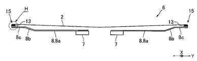
- FIG. 4 is a view showing a front end side portion of the hand fork 6 from the FF direction of FIG.
- FIG. 5 is an enlarged view of a portion G in FIG.
- FIG. 6 is a diagram for explaining the configuration of the H part in FIG. 4.
- the industrial robot of this embodiment is a robot that transports the glass substrate 2 for an organic EL display in a vacuum, and is used by being incorporated in an organic EL display manufacturing system.
- an organic EL display is manufactured by a vacuum deposition method.
- the industrial robot conveys the glass substrate 2 with the deposition surface facing downward.
- the glass substrate 2 is formed in a rectangular plate shape.
- the lower surface of the glass substrate 2 is composed of a rectangular deposition region 2a where deposition is performed and a rectangular frame region 2b (shaded portion in FIG. 2) surrounding the deposition region 2a. It is configured.
- the frame region 2 b constitutes the lower surface of the outer peripheral end portion of the glass substrate 2.
- the industrial robot of this embodiment is a robot suitable for transporting a relatively large glass substrate 2.
- This industrial robot has a hand 3 on which a glass substrate 2 is mounted, an arm 4 (see FIG. 1 (B)) to which the hand 3 is pivotably connected to a tip side thereof, and a base end side of the arm 4 that rotates. And a main body (not shown) that is movably connected.
- the hand 3 and the arm 4 are disposed on the upper side of the main body. Further, the hand 3 and the arm 4 are disposed in a vacuum.
- the hand 3 includes a base 5 connected to the arm 4 and two hand forks 6 on which the glass substrate 2 is mounted.
- the hand fork 6 includes two fork bodies 7.
- the fork main body 7 is formed in the shape of an elongated straight bar.
- the two fork main bodies 7 are arranged in parallel with a predetermined distance from each other. Further, the base end of the fork main body 7 is fixed to the base portion 5.
- Two fork bodies 7 of one hand fork 6 out of the two hand forks 6 are fixed to the base 5 so as to protrude from the base 5 to one side in the horizontal direction, and two of the other hand forks 6
- the fork main body 7 is fixed to the base 5 so as to protrude toward the opposite side of the two fork main bodies 7 protruding to one side in the horizontal direction.
- the longitudinal direction of the fork main body 7 when viewed from the vertical direction is the left-right direction
- the direction perpendicular to the horizontal direction when viewed from the vertical direction is defined as the front-rear direction.
- the end surface of the glass substrate 2 mounted on the hand fork 6 is substantially parallel to the left-right direction or the front-rear direction.
- the hand fork 6 includes a plurality of first fork portions 8 fixed to the front end side of the fork main body 7 and a plurality of second fork portions 9 fixed to the first fork portion 8.
- the glass substrate 2 is mounted on a portion of the hand fork 6 where the first fork portion 8 and the second fork portion 9 are disposed.
- the outer shape of the portion of the hand fork 6 where the first fork portion 8 and the second fork portion 9 are arranged is slightly larger than the outer shape of the glass substrate 2.
- the first fork portion 8 is fixed to the fork main body 7 so as to extend from the two fork main bodies 7 toward the outside in the front-rear direction.
- the plurality of first fork portions 8 are arranged in parallel with a predetermined interval in the left-right direction.
- the seven first fork portions 8 are arranged with a predetermined interval in the left-right direction.
- Each of the plurality of first fork portions 8 fixed to each of the two fork main bodies 7 constituting one hand fork 6 is disposed at the same position in the left-right direction.
- the first fork portion 8 is formed by bending a flat member into a predetermined shape. As shown in FIG. 4, the first fork portion 8 is connected to the elongated flat plate-like base end portion 8a extending from the fork main body 7 toward the outside in the front-rear direction, and the outer end of the base end portion 8a in the front-rear direction and the front-rear direction A flat plate-like inclined portion 8b that is inclined upward toward the outer side of the direction, and a flat plate-like tip portion 8c that is connected to the upper end of the inclined portion 8b and extends outward in the front-rear direction. Yes.
- the second fork portion 9 is formed in an elongated flat plate shape. As shown in FIG. 3, the second fork portion 9 extends from the first fork portion 8 arranged on the outermost side in the left-right direction in one hand fork 6 toward the outer side in the left-right direction. 8 is fixed. That is, in one hand fork 6, the second fork portion 9 is fixed to each of the four first fork portions 8 arranged on the outermost side in the left-right direction. Specifically, a plurality of second fork portions 9 are fixed to each of the four first fork portions 8. The plurality of second fork portions 9 fixed to each of the four first fork portions 8 are arranged in parallel with a predetermined interval in the front-rear direction.
- two second fork portions 9 are fixed to each of the four first fork portions 8.
- Each of the plurality of second fork portions 9 fixed to each of the first fork portions 8 arranged on the outermost side in the left-right direction in one hand fork 6 is arranged at the same position in the front-rear direction.
- the glass substrate 2 is provided on each of the front end side (outer end side in the front-rear direction) of the front end portion 8c of the plurality of first fork parts 8 and the front end side (outer end side in the left-right direction) of the plurality of second fork parts 9.
- a pad 12 (see FIGS. 5 and 6) on which a contact surface 12a that contacts the lower surface is formed is attached.
- the pad holding member 13 formed in a block shape is fixed to the upper surfaces of the distal end sides of the distal end portions 8c of the plurality of first fork portions 8 and the distal end sides of the plurality of second fork portions 9, The pad 12 is fixed to the pad holding member 13.
- the pads 12 are attached to the upper surfaces of the front end sides of the front end portions 8 c of the plurality of first fork portions 8 and the front end sides of the plurality of second fork portions 9 via the pad holding members 13.
- a pad 12 is also attached to the upper surface of each of the two fork main bodies 7 via a pad holding member 13.
- the pad 12 attached to the fork main body 7 is disposed at the same position as the pad 12 attached to the front end side of the second fork portion 9 in the front-rear direction.
- the pad 12 is made of rubber. Specifically, the pad 12 is made of fluororubber. As shown in FIG. 6, the pad 12 includes a contact portion 12b on which the contact surface 12a is formed and a holding portion 12c held on the pad holding member 13, and is formed in a mushroom shape as a whole. Has been.
- the shape of the contact portion 12b is a shape obtained by cutting out a part of a sphere, and is formed in a substantially hemispherical shape.
- the contact surface 12a constitutes the upper surface of the contact portion 12b and is formed in a spherical shape.
- the holding part 12c is formed in a substantially cylindrical shape, and the contact part 12b is connected to the upper end of the holding part 12c. As shown in FIG.
- the holding portion 12 c is press-fitted into a pad holding hole 13 a formed in the pad holding member 13.
- a drop prevention portion 12d that prevents the pad 12 from coming off from the pad holding hole 13a is formed so as to spread outward in the radial direction of the holding portion 12c.
- the pads 12 are attached via the pad holding members 13 to the distal end sides of the distal end portions 8c of the plurality of first fork portions 8 and the distal end sides of the plurality of second fork portions 9, respectively.
- a pad 12 is also attached to each of the two fork main bodies 7 via a pad holding member 13, and the pad 12 attached to the fork main body 7 is attached to the front end side of the second fork portion 9 in the front-rear direction. It is arranged at the same position as the pad 12 to be formed. That is, in this embodiment, the plurality of pads 12 are formed in a substantially rectangular frame shape so that the contact surface 12a contacts the frame region 2b of the glass substrate 2 (that is, the lower surface of the outer peripheral end portion of the glass substrate 2). Are arranged along. Specifically, in this embodiment, three pads 12 are fixed to the pad holding member 13, and a plurality of pad groups 15 constituted by the three pads 12 are arranged along a substantially rectangular frame shape. Has been placed.
- the height of the upper end of the pad 12 attached to the distal end side of the distal end portion 8c of the first fork portion 8, the height of the upper end of the pad 12 attached to the distal end side of the second fork portion 9, and the fork body The height of the pad holding member 13 attached to the front end side of the front end portion 8c of the first fork portion 8 and the front end of the second fork portion 9 are set so that the height of the upper end of the pad 12 attached to the head 7 becomes the same height.
- the height of the pad holding member 13 attached to the side is different from the height of the pad holding member 13 attached to the fork main body 7.
- the pad group 15 contacts the pad 12A when viewed from above and below.
- the pads 12A to 12C are formed on the pad holding member 13 so that virtual lines L1 to L3 connecting the center of the surface 12a, the center of the contact surface 12a of the pad 12B and the center of the contact surface 12a of the pad 12C form an equilateral triangle. It is fixed.
- a virtual line L1 connecting the center of the contact surface 12a of the pad 12A and the center of the contact surface 12a of the pad 12B is substantially the same as the end surface of the glass substrate 2 mounted on the hand fork 6. It is parallel. That is, in the pad group 15 disposed on the distal end side of the distal end portion 8 c of the first fork portion 8, when viewed from the up and down direction, the virtual line L ⁇ b> 1 is the front and rear end surfaces of the glass substrate 2 mounted on the hand fork 6. And substantially parallel (that is, substantially parallel to the left-right direction).
- the virtual line L1 is the left and right end faces of the glass substrate 2 mounted on the hand fork 6 when viewed from the vertical direction. And substantially parallel (that is, substantially parallel to the front-rear direction).
- the pad 12C is disposed outside the pads 12A and 12B in the front-rear direction or the left-right direction. That is, in the pad group 15 disposed on the distal end side of the distal end portion 8c of the first fork portion 8, the pad 12C is disposed on the outer side in the front-rear direction with respect to the pads 12A and 12B, and the distal end side of the second fork portion 9 and In the pad group 15 disposed on the fork main body 7, the pad 12C is disposed on the outer side in the left-right direction with respect to the pads 12A and 12B. That is, the pad 12C is arranged on the outer peripheral side of the glass substrate 2 with respect to the pads 12A and 12B.
- the contact surface 12a of the pad 12A and the contact surface 12a of the pad 12B are in contact with the lower surface (specifically, the frame region 2b) of the glass substrate 2.
- the contact surface 12a of the pad 12C is not in contact with the lower surface of the glass substrate 2 (see FIG. 6).
- the pad 12A is a first pad
- the pad 12B is a second pad
- the pad 12C is a third pad.
- the plurality of pads 12 come into contact with the frame region 2 b of the glass substrate 2, so that the glass substrate 2 mounted on the hand fork 6 is bent.
- This state is schematically shown using contour lines CL as shown in FIG. 2, and the amount of bending of the glass substrate 2 increases as it goes toward the center of the glass substrate 2.
- the plurality of pads 12 are arranged along a substantially rectangular frame shape so that the contact surface 12a of the pad 12 contacts the frame region 2b of the glass substrate 2.
- the glass substrate 2 can be transported by the bottom surface transport that transports the glass substrate 2 with the vapor deposition surface facing downward.
- the contact surface 12a contacts the frame region 2b of the glass substrate 2, the amount of bending of the glass substrate 2 mounted on the hand fork 6 increases, but in this embodiment, on the lower surface of the glass substrate 2 Since the contact surface 12a of the contacting pad 12 is formed in a spherical shape, the contact surface 12a is reliably in contact with the lower surface of the glass substrate 2 even when the amount of bending of the glass substrate 2 mounted on the hand fork 6 increases. It becomes possible to make it. Further, in this embodiment, the contact surface 12a formed in a spherical shape makes point contact with the lower surface of the glass substrate 2, so that the contact pressure between the contact surface 12a and the glass substrate 2 can be increased.
- the contact surface 12a can be reliably brought into contact with the lower surface of the glass substrate 2, and the contact surface It becomes possible to increase the holding pressure of the glass substrate 2 by the hand fork 6 by increasing the contact pressure between the glass substrate 2 and 12a. Therefore, in this embodiment, even if the hand 3 is placed in a vacuum and the hand 3 cannot suck the glass substrate 2, the amount of bending of the glass substrate 2 mounted on the hand fork 6 is large, and Even if the acceleration or deceleration of the hand 3 that moves with the glass substrate 2 mounted thereon is large, it is possible to suppress the displacement of the glass substrate 2 with respect to the hand 3 when the glass substrate 2 is transported. For example, in this embodiment, even if the acceleration of the hand 3 that moves with the glass substrate 2 mounted thereon is 2G, it is possible to suppress the displacement of the glass substrate 2 with respect to the hand 3 when the glass substrate 2 is transported. Become.
- the contact surfaces 12a of the two pads 12A and 12B are in contact with the lower surface of the glass substrate 2. Therefore, in this embodiment, the state of the glass substrate 2 mounted on the hand fork 6 can be stabilized. Further, in this embodiment, since the pad 12C is disposed outside the pads 12A and 12B in the front-rear direction or the left-right direction, for example, the glass substrate 2 placed on the shelf of the vapor deposition apparatus is mounted on the hand fork 6. Even if the glass substrate 2 is shaken at the time, the shake of the glass substrate 2 can be suppressed by the action of the pad 12C. That is, in this embodiment, the pad 12C can prevent the glass substrate 2 from being exposed when the glass substrate 2 is mounted on the hand fork 6.
- the lower surface of the glass substrate 2 is constituted by a rectangular vapor deposition region 2a and a rectangular frame region 2b surrounding the vapor deposition region 2a.
- the lower surface of the glass substrate 2 has four vapor deposition regions 2c formed in a rectangular shape having the same size, as shown in FIG. It may be constituted by a frame region 2f (shaded portion in FIG. 7) composed of a frame region 2d formed in a rectangular frame shape and a cross-shaped partition region 2e that partitions four vapor deposition regions 2c.
- the plurality of pads 12 are arranged along the shape of the frame region 2 f so that the contact surface 12 a contacts the frame region 2 f of the glass substrate 2.
- the state of bending of the glass substrate 2 is schematically shown using contour lines CL as shown in FIG. The amount of bending of the glass substrate 2 increases as it goes to the center.
- the hand 3 includes the base 5, the two fork main bodies 7, the plurality of first fork portions 8, and the plurality of second fork portions 9.
- the hand 3 includes a base portion 25 connected to the arm 4, and a plurality of forks 26 (for example, four forks 26) extending from the base portion 25 in one of the horizontal directions. It may be composed of In this case, as shown in FIG. 8A, a plurality of pads 12 may be attached to the upper surface of the fork 26 so as to support the entire lower surface of the glass substrate 2, or FIG. 4, the four pads 12 may be attached to the upper surface of the fork 26 so as to support the four corners of the lower surface of the glass substrate 2.
- the pad 12C that does not contact the lower surface of the glass substrate 2 mounted on the hand fork 6 is fixed to the pad holding member 13, but the pad 12C may not be fixed to the pad holding member 13.
- one or more pads 12 that contact the lower surface of the glass substrate 2 mounted on the hand fork 6 may be fixed to the pad holding member 13.
- the pads 12A to 12C are fixed to the pad holding member 13 so that the virtual lines L1 to L3 form an equilateral triangle, but the virtual lines L1 to L3 have other isosceles triangles or the like.
- the pads 12A to 12C may be fixed to the pad holding member 13 so as to have a triangular shape.
- the pad 12 is formed of rubber. However, if the pad 12 is formed of a material softer than the coating agent that covers the surface of the glass substrate 2 (that is, the pad 12 is made of the glass substrate 2).
- the pad 12 may be made of a material other than rubber, provided that the surface coating layer is not damaged.
- the pad 12 may be formed of a resin such as polyether ether ketone (PEEK).
- the industrial robot carries the glass substrate 2 for organic EL display, but the industrial robot may carry other glass substrates such as a glass substrate for liquid crystal display.
- the industrial robot is conveying the glass substrate 2 in a vacuum, an industrial robot may be conveying the glass substrate 2 in air
- a suction pad for sucking the glass substrate 2 may be provided on the upper surface of the hand 3.
- the holding force of the glass substrate 2 by the hand fork 6 can be increased by the action of the pad 12, so that even if the suction pad is provided on the upper surface of the hand 3, The number can be reduced.
Landscapes
- Engineering & Computer Science (AREA)
- Robotics (AREA)
- Mechanical Engineering (AREA)
- Physics & Mathematics (AREA)
- Condensed Matter Physics & Semiconductors (AREA)
- General Physics & Mathematics (AREA)
- Manufacturing & Machinery (AREA)
- Computer Hardware Design (AREA)
- Microelectronics & Electronic Packaging (AREA)
- Power Engineering (AREA)
- Container, Conveyance, Adherence, Positioning, Of Wafer (AREA)
- Manipulator (AREA)
Abstract
La présente invention porte sur une main destinée à un robot industriel pour transporter un substrat en verre, laquelle main est apte à minimiser un décalage de position du substrat en verre par rapport à elle-même lors du transport du substrat en verre même quand il y a une grande quantité d'infléchissement appliquée sur le substrat en verre monté sur la main et que l'accélération de la main se déplaçant pendant que le substrat en verre est monté sur celle-ci est élevée. De façon spécifique, ladite main comporte de multiples tampons (12) réalisés en caoutchouc ou en une résine, chacun desdits tampons présentant une surface de contact (12a) qui vient en contact avec la surface inférieure du substrat en verre (2), la surface de contact (12a) étant réalisée sous une forme sphérique.
Priority Applications (3)
| Application Number | Priority Date | Filing Date | Title |
|---|---|---|---|
| KR1020167017554A KR102294719B1 (ko) | 2014-05-16 | 2015-04-25 | 산업용 로봇의 핸드 및 산업용 로봇 |
| CN201580005352.9A CN106414002B (zh) | 2014-05-16 | 2015-04-25 | 产业用机器人的手部及产业用机器人 |
| TW104115075A TWI609749B (zh) | 2014-05-16 | 2015-05-12 | 產業用機器人之手部及產業用機器人 |
Applications Claiming Priority (4)
| Application Number | Priority Date | Filing Date | Title |
|---|---|---|---|
| US201461994226P | 2014-05-16 | 2014-05-16 | |
| US61/994,226 | 2014-05-16 | ||
| JP2014151053A JP6456065B2 (ja) | 2014-05-16 | 2014-07-24 | 産業用ロボットのハンドおよび産業用ロボット |
| JP2014-151053 | 2014-07-24 |
Publications (1)
| Publication Number | Publication Date |
|---|---|
| WO2015174256A1 true WO2015174256A1 (fr) | 2015-11-19 |
Family
ID=54479799
Family Applications (1)
| Application Number | Title | Priority Date | Filing Date |
|---|---|---|---|
| PCT/JP2015/062622 WO2015174256A1 (fr) | 2014-05-16 | 2015-04-25 | Main pour robot industriel et robot industriel |
Country Status (1)
| Country | Link |
|---|---|
| WO (1) | WO2015174256A1 (fr) |
Citations (2)
| Publication number | Priority date | Publication date | Assignee | Title |
|---|---|---|---|---|
| JP2000100903A (ja) * | 1998-09-22 | 2000-04-07 | Olympus Optical Co Ltd | 基板保持装置 |
| JP2009141091A (ja) * | 2007-12-06 | 2009-06-25 | Tokyo Electron Ltd | 基板保持具、基板搬送装置および基板処理システム |
-
2015
- 2015-04-25 WO PCT/JP2015/062622 patent/WO2015174256A1/fr active Application Filing
Patent Citations (2)
| Publication number | Priority date | Publication date | Assignee | Title |
|---|---|---|---|---|
| JP2000100903A (ja) * | 1998-09-22 | 2000-04-07 | Olympus Optical Co Ltd | 基板保持装置 |
| JP2009141091A (ja) * | 2007-12-06 | 2009-06-25 | Tokyo Electron Ltd | 基板保持具、基板搬送装置および基板処理システム |
Similar Documents
| Publication | Publication Date | Title |
|---|---|---|
| JP4873895B2 (ja) | 平板状搬送物の搬送方法及びその装置 | |
| JP6792824B2 (ja) | 板ガラスの製造方法及び板ガラスの折割装置 | |
| JP5589790B2 (ja) | 基板搬送用ハンドおよび基板搬送ロボット | |
| US20090290960A1 (en) | Apparatus for moving and securing a substrate | |
| JP2010188465A (ja) | ロボットハンド | |
| JP6456065B2 (ja) | 産業用ロボットのハンドおよび産業用ロボット | |
| CN107403744A (zh) | 基板搬送装置 | |
| CN112010032A (zh) | 末端执行器以及拣选系统 | |
| WO2015174256A1 (fr) | Main pour robot industriel et robot industriel | |
| JP2019010692A (ja) | 産業用ロボットのハンドおよび産業用ロボット | |
| KR101989322B1 (ko) | 필름을 이송하기 위한 로봇 핸드 | |
| CN211137181U (zh) | 工业用机器人的手以及工业用机器人 | |
| KR100962953B1 (ko) | 유리 기판 이송용 로봇 | |
| JP4574453B2 (ja) | 基板吸着装置と基板支持体および基板搬送装置 | |
| TWI650830B (zh) | 脆性材料基板的搬送方法及搬送裝置 | |
| JP2008112902A (ja) | 基板の支持方法及び支持構造 | |
| CN104249933B (zh) | 脆性材料基板的搬送方法及搬送装置 | |
| US10373856B2 (en) | Transfer head array | |
| TWM405428U (en) | Semiconductor conveyor belt structure | |
| JP2017148891A (ja) | ロボットハンド | |
| KR102385265B1 (ko) | 물품 반송 장치 및 오버 헤드 트랜스퍼 장치 | |
| JP6873881B2 (ja) | 産業用ロボット | |
| JP6555100B2 (ja) | 基板装置の製造方法 | |
| KR101678375B1 (ko) | 기판 처짐 및 왜곡 현상을 감소시키기 위한 기판 이송 장치 및 이를 포함한 기판 로딩 장치 | |
| TW201930167A (zh) | 基板吸附裝置 |
Legal Events
| Date | Code | Title | Description |
|---|---|---|---|
| 121 | Ep: the epo has been informed by wipo that ep was designated in this application |
Ref document number: 15793274 Country of ref document: EP Kind code of ref document: A1 |
|
| ENP | Entry into the national phase |
Ref document number: 20167017554 Country of ref document: KR Kind code of ref document: A |
|
| NENP | Non-entry into the national phase |
Ref country code: DE |
|
| 122 | Ep: pct application non-entry in european phase |
Ref document number: 15793274 Country of ref document: EP Kind code of ref document: A1 |