WO2015174256A1 - Hand for industrial robot and industrial robot - Google Patents
Hand for industrial robot and industrial robot Download PDFInfo
- Publication number
- WO2015174256A1 WO2015174256A1 PCT/JP2015/062622 JP2015062622W WO2015174256A1 WO 2015174256 A1 WO2015174256 A1 WO 2015174256A1 JP 2015062622 W JP2015062622 W JP 2015062622W WO 2015174256 A1 WO2015174256 A1 WO 2015174256A1
- Authority
- WO
- WIPO (PCT)
- Prior art keywords
- glass substrate
- pad
- hand
- fork
- contact surface
- Prior art date
Links
Images


Classifications
-
- B—PERFORMING OPERATIONS; TRANSPORTING
- B25—HAND TOOLS; PORTABLE POWER-DRIVEN TOOLS; MANIPULATORS
- B25J—MANIPULATORS; CHAMBERS PROVIDED WITH MANIPULATION DEVICES
- B25J15/00—Gripping heads and other end effectors
-
- B—PERFORMING OPERATIONS; TRANSPORTING
- B25—HAND TOOLS; PORTABLE POWER-DRIVEN TOOLS; MANIPULATORS
- B25J—MANIPULATORS; CHAMBERS PROVIDED WITH MANIPULATION DEVICES
- B25J15/00—Gripping heads and other end effectors
- B25J15/08—Gripping heads and other end effectors having finger members
-
- B—PERFORMING OPERATIONS; TRANSPORTING
- B65—CONVEYING; PACKING; STORING; HANDLING THIN OR FILAMENTARY MATERIAL
- B65G—TRANSPORT OR STORAGE DEVICES, e.g. CONVEYORS FOR LOADING OR TIPPING, SHOP CONVEYOR SYSTEMS OR PNEUMATIC TUBE CONVEYORS
- B65G49/00—Conveying systems characterised by their application for specified purposes not otherwise provided for
- B65G49/05—Conveying systems characterised by their application for specified purposes not otherwise provided for for fragile or damageable materials or articles
- B65G49/06—Conveying systems characterised by their application for specified purposes not otherwise provided for for fragile or damageable materials or articles for fragile sheets, e.g. glass
-
- H—ELECTRICITY
- H01—ELECTRIC ELEMENTS
- H01L—SEMICONDUCTOR DEVICES NOT COVERED BY CLASS H10
- H01L21/00—Processes or apparatus adapted for the manufacture or treatment of semiconductor or solid state devices or of parts thereof
- H01L21/67—Apparatus specially adapted for handling semiconductor or electric solid state devices during manufacture or treatment thereof; Apparatus specially adapted for handling wafers during manufacture or treatment of semiconductor or electric solid state devices or components ; Apparatus not specifically provided for elsewhere
- H01L21/677—Apparatus specially adapted for handling semiconductor or electric solid state devices during manufacture or treatment thereof; Apparatus specially adapted for handling wafers during manufacture or treatment of semiconductor or electric solid state devices or components ; Apparatus not specifically provided for elsewhere for conveying, e.g. between different workstations
Definitions
- the present invention relates to an industrial robot hand for conveying a glass substrate.
- the present invention also relates to an industrial robot provided with such a hand.
- an organic EL device manufacturing apparatus for manufacturing an organic EL device by a vacuum deposition method is known (for example, see Patent Document 1).
- the organic EL device manufacturing apparatus described in Patent Document 1 includes a transfer robot that transfers a glass substrate.
- a so-called bottom surface transport is generally known in which a glass substrate is transported with a deposition surface facing downward.
- the conveyance robot When the glass substrate is conveyed by the lower surface conveyance, the conveyance robot cannot touch the vapor deposition surface because the lower surface of the glass substrate is the vapor deposition surface. Therefore, when the glass substrate is transported by the bottom surface transport, the transport robot mounts the glass substrate on the hand so that the hand contacts the frame portion formed around the deposition surface, and transports the glass substrate. ing.
- an O-ring may be attached to the upper surface of the hand on which the glass substrate is mounted in order to prevent the glass substrate from being displaced relative to the hand when the glass substrate is conveyed.
- the problem of the present invention is that, in an industrial robot hand that conveys a glass substrate, the amount of bending of the glass substrate mounted on the hand is large, and even if the acceleration of the hand moving with the glass substrate mounted is large.
- Another object of the present invention is to provide an industrial robot hand capable of suppressing the displacement of the glass substrate relative to the hand when the glass substrate is conveyed.
- the subject of this invention is providing an industrial robot provided with this hand.
- an industrial robot hand is an industrial robot hand that transports a glass substrate, and a contact surface that contacts the lower surface of the glass substrate in the hand on which the glass substrate is mounted.
- a plurality of pads made of rubber or resin are formed, and the contact surface is formed in a spherical shape.
- the contact surface of the pad that contacts the lower surface of the glass substrate is formed in a spherical shape. Therefore, in the present invention, even if the amount of bending of the glass substrate mounted on the hand increases, the contact surface of the pad can be reliably brought into contact with the lower surface of the glass substrate. Moreover, in this invention, since the contact surface formed in spherical shape makes point contact with the lower surface of a glass substrate, it becomes possible to raise the contact pressure of a contact surface and a glass substrate.
- the contact surface can be reliably brought into contact with the lower surface of the glass substrate, and the contact surface and the glass substrate can be brought into contact with each other. It becomes possible to increase the holding pressure of the glass substrate by the hand by increasing the contact pressure. Therefore, in the present invention, the position of the glass substrate relative to the hand when transporting the glass substrate is large even if the amount of bending of the glass substrate mounted on the hand is large and the acceleration of the hand moving with the glass substrate mounted is large. The shift can be suppressed.
- the glass substrate is formed in a rectangular shape, and the plurality of pads are formed in a substantially rectangular frame shape so that the contact surface contacts the lower surface of the outer peripheral end portion of the glass substrate formed in a rectangular shape. It is preferable to arrange along.
- the glass substrate is transported by the bottom surface transport that transports the glass substrate with the deposition surface facing downward, and the amount of bending of the glass substrate mounted on the hand is large, and Even when the acceleration of the hand moving with the glass substrate mounted is large, it is possible to suppress the positional deviation of the glass substrate with respect to the hand when the glass substrate is transported.
- a plurality of pad groups constituted by three pads, the first pad, the second pad, and the third pad, are arranged along a substantially rectangular frame shape, and the pad group is viewed from the up and down direction.
- the first pad and the second pad so that a virtual line connecting the center of the contact surface of the first pad, the center of the contact surface of the second pad and the center of the contact surface of the third pad forms a triangular shape.
- a virtual line connecting the center of the contact surface of the first pad and the center of the contact surface of the second pad is substantially parallel to the end surface of the glass substrate when the pad and the third pad are arranged and viewed from above and below.
- the third pad is disposed on the outer peripheral side of the glass substrate relative to the first pad and the second pad, and when the glass substrate is mounted on the hand, the contact surface of the first pad and the second pad The contact surface is in contact with the lower surface of the glass substrate It is preferable.
- each pad group since the contact surface of two pads contacts the lower surface of a glass substrate, when conveying a glass substrate, the state of the glass substrate mounted in a hand can be stabilized. It becomes possible. Moreover, since the 3rd pad is arrange
- the hand of the present invention can be used for an industrial robot including an arm that is pivotally connected to the tip side of the hand and a main body that is pivotally connected to the base end side of the arm.
- an industrial robot including an arm that is pivotally connected to the tip side of the hand and a main body that is pivotally connected to the base end side of the arm.
- the hand is arranged in a vacuum, for example.
- the hand cannot suck and hold the glass substrate.
- the hand even if the hand cannot suck the glass substrate, it is mounted on the hand. Even if the amount of bending of the glass substrate is large and the acceleration of the hand moving with the glass substrate mounted thereon is large, it is possible to suppress the displacement of the glass substrate relative to the hand when the glass substrate is transported.
- the present invention even when the amount of bending of the glass substrate mounted on the hand is large and the acceleration of the hand moving with the glass substrate mounted is large, the glass with respect to the hand when the glass substrate is transported It is possible to suppress the displacement of the substrate.
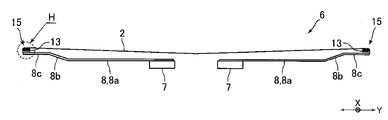
- FIG. 4 is a view showing a tip side portion of the hand fork from the FF direction of FIG. It is an enlarged view of the G section of FIG. It is a figure for demonstrating the structure of the H section of FIG. It is a top view for demonstrating the structure of the glass substrate concerning other embodiment of this invention. It is a top view of the hand concerning other embodiments of the present invention.
- FIG. 1 is a diagram of a hand 3 according to an embodiment of the present invention, where (A) is a plan view and (B) is a side view.
- FIG. 2 is a plan view for explaining the configuration of the glass substrate 2 shown in FIG.
- FIG. 3 is an enlarged view of a portion E in FIG.
- FIG. 4 is a view showing a front end side portion of the hand fork 6 from the FF direction of FIG.
- FIG. 5 is an enlarged view of a portion G in FIG.
- FIG. 6 is a diagram for explaining the configuration of the H part in FIG. 4.
- the industrial robot of this embodiment is a robot that transports the glass substrate 2 for an organic EL display in a vacuum, and is used by being incorporated in an organic EL display manufacturing system.
- an organic EL display is manufactured by a vacuum deposition method.
- the industrial robot conveys the glass substrate 2 with the deposition surface facing downward.
- the glass substrate 2 is formed in a rectangular plate shape.
- the lower surface of the glass substrate 2 is composed of a rectangular deposition region 2a where deposition is performed and a rectangular frame region 2b (shaded portion in FIG. 2) surrounding the deposition region 2a. It is configured.
- the frame region 2 b constitutes the lower surface of the outer peripheral end portion of the glass substrate 2.
- the industrial robot of this embodiment is a robot suitable for transporting a relatively large glass substrate 2.
- This industrial robot has a hand 3 on which a glass substrate 2 is mounted, an arm 4 (see FIG. 1 (B)) to which the hand 3 is pivotably connected to a tip side thereof, and a base end side of the arm 4 that rotates. And a main body (not shown) that is movably connected.
- the hand 3 and the arm 4 are disposed on the upper side of the main body. Further, the hand 3 and the arm 4 are disposed in a vacuum.
- the hand 3 includes a base 5 connected to the arm 4 and two hand forks 6 on which the glass substrate 2 is mounted.
- the hand fork 6 includes two fork bodies 7.
- the fork main body 7 is formed in the shape of an elongated straight bar.
- the two fork main bodies 7 are arranged in parallel with a predetermined distance from each other. Further, the base end of the fork main body 7 is fixed to the base portion 5.
- Two fork bodies 7 of one hand fork 6 out of the two hand forks 6 are fixed to the base 5 so as to protrude from the base 5 to one side in the horizontal direction, and two of the other hand forks 6
- the fork main body 7 is fixed to the base 5 so as to protrude toward the opposite side of the two fork main bodies 7 protruding to one side in the horizontal direction.
- the longitudinal direction of the fork main body 7 when viewed from the vertical direction is the left-right direction
- the direction perpendicular to the horizontal direction when viewed from the vertical direction is defined as the front-rear direction.
- the end surface of the glass substrate 2 mounted on the hand fork 6 is substantially parallel to the left-right direction or the front-rear direction.
- the hand fork 6 includes a plurality of first fork portions 8 fixed to the front end side of the fork main body 7 and a plurality of second fork portions 9 fixed to the first fork portion 8.
- the glass substrate 2 is mounted on a portion of the hand fork 6 where the first fork portion 8 and the second fork portion 9 are disposed.
- the outer shape of the portion of the hand fork 6 where the first fork portion 8 and the second fork portion 9 are arranged is slightly larger than the outer shape of the glass substrate 2.
- the first fork portion 8 is fixed to the fork main body 7 so as to extend from the two fork main bodies 7 toward the outside in the front-rear direction.
- the plurality of first fork portions 8 are arranged in parallel with a predetermined interval in the left-right direction.
- the seven first fork portions 8 are arranged with a predetermined interval in the left-right direction.
- Each of the plurality of first fork portions 8 fixed to each of the two fork main bodies 7 constituting one hand fork 6 is disposed at the same position in the left-right direction.
- the first fork portion 8 is formed by bending a flat member into a predetermined shape. As shown in FIG. 4, the first fork portion 8 is connected to the elongated flat plate-like base end portion 8a extending from the fork main body 7 toward the outside in the front-rear direction, and the outer end of the base end portion 8a in the front-rear direction and the front-rear direction A flat plate-like inclined portion 8b that is inclined upward toward the outer side of the direction, and a flat plate-like tip portion 8c that is connected to the upper end of the inclined portion 8b and extends outward in the front-rear direction. Yes.
- the second fork portion 9 is formed in an elongated flat plate shape. As shown in FIG. 3, the second fork portion 9 extends from the first fork portion 8 arranged on the outermost side in the left-right direction in one hand fork 6 toward the outer side in the left-right direction. 8 is fixed. That is, in one hand fork 6, the second fork portion 9 is fixed to each of the four first fork portions 8 arranged on the outermost side in the left-right direction. Specifically, a plurality of second fork portions 9 are fixed to each of the four first fork portions 8. The plurality of second fork portions 9 fixed to each of the four first fork portions 8 are arranged in parallel with a predetermined interval in the front-rear direction.
- two second fork portions 9 are fixed to each of the four first fork portions 8.
- Each of the plurality of second fork portions 9 fixed to each of the first fork portions 8 arranged on the outermost side in the left-right direction in one hand fork 6 is arranged at the same position in the front-rear direction.
- the glass substrate 2 is provided on each of the front end side (outer end side in the front-rear direction) of the front end portion 8c of the plurality of first fork parts 8 and the front end side (outer end side in the left-right direction) of the plurality of second fork parts 9.
- a pad 12 (see FIGS. 5 and 6) on which a contact surface 12a that contacts the lower surface is formed is attached.
- the pad holding member 13 formed in a block shape is fixed to the upper surfaces of the distal end sides of the distal end portions 8c of the plurality of first fork portions 8 and the distal end sides of the plurality of second fork portions 9, The pad 12 is fixed to the pad holding member 13.
- the pads 12 are attached to the upper surfaces of the front end sides of the front end portions 8 c of the plurality of first fork portions 8 and the front end sides of the plurality of second fork portions 9 via the pad holding members 13.
- a pad 12 is also attached to the upper surface of each of the two fork main bodies 7 via a pad holding member 13.
- the pad 12 attached to the fork main body 7 is disposed at the same position as the pad 12 attached to the front end side of the second fork portion 9 in the front-rear direction.
- the pad 12 is made of rubber. Specifically, the pad 12 is made of fluororubber. As shown in FIG. 6, the pad 12 includes a contact portion 12b on which the contact surface 12a is formed and a holding portion 12c held on the pad holding member 13, and is formed in a mushroom shape as a whole. Has been.
- the shape of the contact portion 12b is a shape obtained by cutting out a part of a sphere, and is formed in a substantially hemispherical shape.
- the contact surface 12a constitutes the upper surface of the contact portion 12b and is formed in a spherical shape.
- the holding part 12c is formed in a substantially cylindrical shape, and the contact part 12b is connected to the upper end of the holding part 12c. As shown in FIG.
- the holding portion 12 c is press-fitted into a pad holding hole 13 a formed in the pad holding member 13.
- a drop prevention portion 12d that prevents the pad 12 from coming off from the pad holding hole 13a is formed so as to spread outward in the radial direction of the holding portion 12c.
- the pads 12 are attached via the pad holding members 13 to the distal end sides of the distal end portions 8c of the plurality of first fork portions 8 and the distal end sides of the plurality of second fork portions 9, respectively.
- a pad 12 is also attached to each of the two fork main bodies 7 via a pad holding member 13, and the pad 12 attached to the fork main body 7 is attached to the front end side of the second fork portion 9 in the front-rear direction. It is arranged at the same position as the pad 12 to be formed. That is, in this embodiment, the plurality of pads 12 are formed in a substantially rectangular frame shape so that the contact surface 12a contacts the frame region 2b of the glass substrate 2 (that is, the lower surface of the outer peripheral end portion of the glass substrate 2). Are arranged along. Specifically, in this embodiment, three pads 12 are fixed to the pad holding member 13, and a plurality of pad groups 15 constituted by the three pads 12 are arranged along a substantially rectangular frame shape. Has been placed.
- the height of the upper end of the pad 12 attached to the distal end side of the distal end portion 8c of the first fork portion 8, the height of the upper end of the pad 12 attached to the distal end side of the second fork portion 9, and the fork body The height of the pad holding member 13 attached to the front end side of the front end portion 8c of the first fork portion 8 and the front end of the second fork portion 9 are set so that the height of the upper end of the pad 12 attached to the head 7 becomes the same height.
- the height of the pad holding member 13 attached to the side is different from the height of the pad holding member 13 attached to the fork main body 7.
- the pad group 15 contacts the pad 12A when viewed from above and below.
- the pads 12A to 12C are formed on the pad holding member 13 so that virtual lines L1 to L3 connecting the center of the surface 12a, the center of the contact surface 12a of the pad 12B and the center of the contact surface 12a of the pad 12C form an equilateral triangle. It is fixed.
- a virtual line L1 connecting the center of the contact surface 12a of the pad 12A and the center of the contact surface 12a of the pad 12B is substantially the same as the end surface of the glass substrate 2 mounted on the hand fork 6. It is parallel. That is, in the pad group 15 disposed on the distal end side of the distal end portion 8 c of the first fork portion 8, when viewed from the up and down direction, the virtual line L ⁇ b> 1 is the front and rear end surfaces of the glass substrate 2 mounted on the hand fork 6. And substantially parallel (that is, substantially parallel to the left-right direction).
- the virtual line L1 is the left and right end faces of the glass substrate 2 mounted on the hand fork 6 when viewed from the vertical direction. And substantially parallel (that is, substantially parallel to the front-rear direction).
- the pad 12C is disposed outside the pads 12A and 12B in the front-rear direction or the left-right direction. That is, in the pad group 15 disposed on the distal end side of the distal end portion 8c of the first fork portion 8, the pad 12C is disposed on the outer side in the front-rear direction with respect to the pads 12A and 12B, and the distal end side of the second fork portion 9 and In the pad group 15 disposed on the fork main body 7, the pad 12C is disposed on the outer side in the left-right direction with respect to the pads 12A and 12B. That is, the pad 12C is arranged on the outer peripheral side of the glass substrate 2 with respect to the pads 12A and 12B.
- the contact surface 12a of the pad 12A and the contact surface 12a of the pad 12B are in contact with the lower surface (specifically, the frame region 2b) of the glass substrate 2.
- the contact surface 12a of the pad 12C is not in contact with the lower surface of the glass substrate 2 (see FIG. 6).
- the pad 12A is a first pad
- the pad 12B is a second pad
- the pad 12C is a third pad.
- the plurality of pads 12 come into contact with the frame region 2 b of the glass substrate 2, so that the glass substrate 2 mounted on the hand fork 6 is bent.
- This state is schematically shown using contour lines CL as shown in FIG. 2, and the amount of bending of the glass substrate 2 increases as it goes toward the center of the glass substrate 2.
- the plurality of pads 12 are arranged along a substantially rectangular frame shape so that the contact surface 12a of the pad 12 contacts the frame region 2b of the glass substrate 2.
- the glass substrate 2 can be transported by the bottom surface transport that transports the glass substrate 2 with the vapor deposition surface facing downward.
- the contact surface 12a contacts the frame region 2b of the glass substrate 2, the amount of bending of the glass substrate 2 mounted on the hand fork 6 increases, but in this embodiment, on the lower surface of the glass substrate 2 Since the contact surface 12a of the contacting pad 12 is formed in a spherical shape, the contact surface 12a is reliably in contact with the lower surface of the glass substrate 2 even when the amount of bending of the glass substrate 2 mounted on the hand fork 6 increases. It becomes possible to make it. Further, in this embodiment, the contact surface 12a formed in a spherical shape makes point contact with the lower surface of the glass substrate 2, so that the contact pressure between the contact surface 12a and the glass substrate 2 can be increased.
- the contact surface 12a can be reliably brought into contact with the lower surface of the glass substrate 2, and the contact surface It becomes possible to increase the holding pressure of the glass substrate 2 by the hand fork 6 by increasing the contact pressure between the glass substrate 2 and 12a. Therefore, in this embodiment, even if the hand 3 is placed in a vacuum and the hand 3 cannot suck the glass substrate 2, the amount of bending of the glass substrate 2 mounted on the hand fork 6 is large, and Even if the acceleration or deceleration of the hand 3 that moves with the glass substrate 2 mounted thereon is large, it is possible to suppress the displacement of the glass substrate 2 with respect to the hand 3 when the glass substrate 2 is transported. For example, in this embodiment, even if the acceleration of the hand 3 that moves with the glass substrate 2 mounted thereon is 2G, it is possible to suppress the displacement of the glass substrate 2 with respect to the hand 3 when the glass substrate 2 is transported. Become.
- the contact surfaces 12a of the two pads 12A and 12B are in contact with the lower surface of the glass substrate 2. Therefore, in this embodiment, the state of the glass substrate 2 mounted on the hand fork 6 can be stabilized. Further, in this embodiment, since the pad 12C is disposed outside the pads 12A and 12B in the front-rear direction or the left-right direction, for example, the glass substrate 2 placed on the shelf of the vapor deposition apparatus is mounted on the hand fork 6. Even if the glass substrate 2 is shaken at the time, the shake of the glass substrate 2 can be suppressed by the action of the pad 12C. That is, in this embodiment, the pad 12C can prevent the glass substrate 2 from being exposed when the glass substrate 2 is mounted on the hand fork 6.
- the lower surface of the glass substrate 2 is constituted by a rectangular vapor deposition region 2a and a rectangular frame region 2b surrounding the vapor deposition region 2a.
- the lower surface of the glass substrate 2 has four vapor deposition regions 2c formed in a rectangular shape having the same size, as shown in FIG. It may be constituted by a frame region 2f (shaded portion in FIG. 7) composed of a frame region 2d formed in a rectangular frame shape and a cross-shaped partition region 2e that partitions four vapor deposition regions 2c.
- the plurality of pads 12 are arranged along the shape of the frame region 2 f so that the contact surface 12 a contacts the frame region 2 f of the glass substrate 2.
- the state of bending of the glass substrate 2 is schematically shown using contour lines CL as shown in FIG. The amount of bending of the glass substrate 2 increases as it goes to the center.
- the hand 3 includes the base 5, the two fork main bodies 7, the plurality of first fork portions 8, and the plurality of second fork portions 9.
- the hand 3 includes a base portion 25 connected to the arm 4, and a plurality of forks 26 (for example, four forks 26) extending from the base portion 25 in one of the horizontal directions. It may be composed of In this case, as shown in FIG. 8A, a plurality of pads 12 may be attached to the upper surface of the fork 26 so as to support the entire lower surface of the glass substrate 2, or FIG. 4, the four pads 12 may be attached to the upper surface of the fork 26 so as to support the four corners of the lower surface of the glass substrate 2.
- the pad 12C that does not contact the lower surface of the glass substrate 2 mounted on the hand fork 6 is fixed to the pad holding member 13, but the pad 12C may not be fixed to the pad holding member 13.
- one or more pads 12 that contact the lower surface of the glass substrate 2 mounted on the hand fork 6 may be fixed to the pad holding member 13.
- the pads 12A to 12C are fixed to the pad holding member 13 so that the virtual lines L1 to L3 form an equilateral triangle, but the virtual lines L1 to L3 have other isosceles triangles or the like.
- the pads 12A to 12C may be fixed to the pad holding member 13 so as to have a triangular shape.
- the pad 12 is formed of rubber. However, if the pad 12 is formed of a material softer than the coating agent that covers the surface of the glass substrate 2 (that is, the pad 12 is made of the glass substrate 2).
- the pad 12 may be made of a material other than rubber, provided that the surface coating layer is not damaged.
- the pad 12 may be formed of a resin such as polyether ether ketone (PEEK).
- the industrial robot carries the glass substrate 2 for organic EL display, but the industrial robot may carry other glass substrates such as a glass substrate for liquid crystal display.
- the industrial robot is conveying the glass substrate 2 in a vacuum, an industrial robot may be conveying the glass substrate 2 in air
- a suction pad for sucking the glass substrate 2 may be provided on the upper surface of the hand 3.
- the holding force of the glass substrate 2 by the hand fork 6 can be increased by the action of the pad 12, so that even if the suction pad is provided on the upper surface of the hand 3, The number can be reduced.
Abstract
The present invention provides a hand for an industrial robot for conveying a glass substrate such that the hand is capable of minimizing positional shifting of the glass substrate relative to the hand when conveying the glass substrate even when there is a large amount of deflection on the glass substrate mounted on the hand and the acceleration of the hand moving while the glass substrate is mounted thereon is high. Specifically, this hand is equipped with multiple pads (12) made of rubber or a resin, each of said pads having a contact surface (12a) which comes into contact with the bottom surface of the glass substrate (2), wherein the contact surface (12a) is formed into a spherical shape.
Description
本発明は、ガラス基板を搬送する産業用ロボットのハンドに関する。また、本発明は、かかるハンドを備える産業用ロボットに関する。
The present invention relates to an industrial robot hand for conveying a glass substrate. The present invention also relates to an industrial robot provided with such a hand.
従来、真空蒸着法によって有機ELデバイスを製造する有機ELデバイス製造装置が知られている(たとえば、特許文献1参照)。特許文献1に記載の有機ELデバイス製造装置は、ガラス基板を搬送する搬送ロボットを備えている。また、真空蒸着法によって有機ELデバイスを製造する際のガラス基板の搬送方法として、一般に、蒸着面を下側に向けた状態でガラス基板を搬送するいわゆる下面搬送が知られている。
Conventionally, an organic EL device manufacturing apparatus for manufacturing an organic EL device by a vacuum deposition method is known (for example, see Patent Document 1). The organic EL device manufacturing apparatus described in Patent Document 1 includes a transfer robot that transfers a glass substrate. Further, as a method for transporting a glass substrate when manufacturing an organic EL device by a vacuum deposition method, a so-called bottom surface transport is generally known in which a glass substrate is transported with a deposition surface facing downward.
下面搬送でガラス基板が搬送される場合、ガラス基板の下面が蒸着面であるため、搬送ロボットは、蒸着面に触れることができない。したがって、下面搬送でガラス基板が搬送される場合には、搬送ロボットは、蒸着面の周囲に形成される枠部分にハンドが接触するようにハンドにガラス基板を搭載して、ガラス基板を搬送している。この場合、ガラス基板を搬送する際のハンドに対するガラス基板の位置ずれを防止するために、ガラス基板が搭載されるハンドの上面にOリングが取り付けられることがある。
When the glass substrate is conveyed by the lower surface conveyance, the conveyance robot cannot touch the vapor deposition surface because the lower surface of the glass substrate is the vapor deposition surface. Therefore, when the glass substrate is transported by the bottom surface transport, the transport robot mounts the glass substrate on the hand so that the hand contacts the frame portion formed around the deposition surface, and transports the glass substrate. ing. In this case, an O-ring may be attached to the upper surface of the hand on which the glass substrate is mounted in order to prevent the glass substrate from being displaced relative to the hand when the glass substrate is conveyed.
近年、有機ELデバイス製造装置等の搬送ロボットで搬送されるガラス基板は大型化している。ガラス基板が大型化すると、下面搬送でガラス基板が搬送される場合、蒸着面の周囲の枠部分にハンドが接触するようにハンドに搭載されたガラス基板の撓み量が大きくなる。また、近年、有機ELデバイス製造装置等の搬送ロボットに対して、ガラス基板の搬送時間の短縮化の要求が高まっている。本願発明者の検討によると、ハンドに搭載されたガラス基板の撓み量が大きくなると、また、ガラス基板の搬送時間を短縮するために、ガラス基板を搭載して移動するハンドの加速度を大きくすると、ハンドの上面にOリングが取り付けられていても、ガラス基板を搬送する際のハンドに対するガラス基板の位置ずれが生じることが明らかになった。
In recent years, glass substrates transported by transport robots such as organic EL device manufacturing apparatuses have become larger. When the glass substrate is enlarged, when the glass substrate is transported by the bottom surface transport, the amount of bending of the glass substrate mounted on the hand increases so that the hand contacts the frame portion around the vapor deposition surface. In recent years, there has been an increasing demand for shortening the time for transporting glass substrates to transport robots such as organic EL device manufacturing apparatuses. According to the inventor's study, when the amount of bending of the glass substrate mounted on the hand increases, and in order to reduce the transport time of the glass substrate, the acceleration of the hand moving with the glass substrate mounted is increased. Even when the O-ring is attached to the upper surface of the hand, it has been found that the glass substrate is displaced relative to the hand when the glass substrate is transported.
そこで、本発明の課題は、ガラス基板を搬送する産業用ロボットのハンドにおいて、ハンドに搭載されたガラス基板の撓み量が大きく、かつ、ガラス基板を搭載して移動するハンドの加速度が大きくても、ガラス基板を搬送する際のハンドに対するガラス基板の位置ずれを抑制することが可能な産業用ロボットのハンドを提供することにある。また、本発明の課題は、かかるハンドを備える産業用ロボットを提供することにある。
Therefore, the problem of the present invention is that, in an industrial robot hand that conveys a glass substrate, the amount of bending of the glass substrate mounted on the hand is large, and even if the acceleration of the hand moving with the glass substrate mounted is large. Another object of the present invention is to provide an industrial robot hand capable of suppressing the displacement of the glass substrate relative to the hand when the glass substrate is conveyed. Moreover, the subject of this invention is providing an industrial robot provided with this hand.
上記の課題を解決するため、本発明の産業用ロボットのハンドは、ガラス基板を搬送する産業用ロボットのハンドであって、ガラス基板が搭載されるハンドにおいて、ガラス基板の下面に接触する接触面が形成されるゴム製または樹脂製の複数のパッドを備え、接触面は、球面状に形成されていることを特徴とする。
In order to solve the above-described problems, an industrial robot hand according to the present invention is an industrial robot hand that transports a glass substrate, and a contact surface that contacts the lower surface of the glass substrate in the hand on which the glass substrate is mounted. A plurality of pads made of rubber or resin are formed, and the contact surface is formed in a spherical shape.
本発明の産業用ロボットのハンドでは、ガラス基板の下面に接触するパッドの接触面が球面状に形成されている。そのため、本発明では、ハンドに搭載されたガラス基板の撓み量が大きくなっても、ガラス基板の下面にパッドの接触面を確実に接触させることが可能になる。また、本発明では、球面状に形成される接触面がガラス基板の下面に点接触するため、接触面とガラス基板との接触圧を高めることが可能になる。このように、本発明では、ハンドに搭載されたガラス基板の撓み量が大きくなっても、ガラス基板の下面に接触面を確実に接触させることが可能になるとともに、接触面とガラス基板との接触圧を高めてハンドによるガラス基板の保持力を高めることが可能になる。したがって、本発明では、ハンドに搭載されたガラス基板の撓み量が大きく、かつ、ガラス基板を搭載して移動するハンドの加速度が大きくても、ガラス基板を搬送する際のハンドに対するガラス基板の位置ずれを抑制することが可能になる。
In the industrial robot hand of the present invention, the contact surface of the pad that contacts the lower surface of the glass substrate is formed in a spherical shape. Therefore, in the present invention, even if the amount of bending of the glass substrate mounted on the hand increases, the contact surface of the pad can be reliably brought into contact with the lower surface of the glass substrate. Moreover, in this invention, since the contact surface formed in spherical shape makes point contact with the lower surface of a glass substrate, it becomes possible to raise the contact pressure of a contact surface and a glass substrate. Thus, in the present invention, even if the amount of bending of the glass substrate mounted on the hand increases, the contact surface can be reliably brought into contact with the lower surface of the glass substrate, and the contact surface and the glass substrate can be brought into contact with each other. It becomes possible to increase the holding pressure of the glass substrate by the hand by increasing the contact pressure. Therefore, in the present invention, the position of the glass substrate relative to the hand when transporting the glass substrate is large even if the amount of bending of the glass substrate mounted on the hand is large and the acceleration of the hand moving with the glass substrate mounted is large. The shift can be suppressed.
本発明において、ガラス基板は、長方形状に形成され、複数のパッドは、長方形状に形成されるガラス基板の外周端部分の下面に接触面が接触するように、略長方形の枠状の形状に沿って配置されていることが好ましい。このように構成すると、蒸着面を下側に向けた状態でガラス基板を搬送する下面搬送によってガラス基板が搬送される場合であって、ハンドに搭載されたガラス基板の撓み量が大きく、かつ、ガラス基板を搭載して移動するハンドの加速度が大きい場合であっても、ガラス基板を搬送する際のハンドに対するガラス基板の位置ずれを抑制することが可能になる。
In the present invention, the glass substrate is formed in a rectangular shape, and the plurality of pads are formed in a substantially rectangular frame shape so that the contact surface contacts the lower surface of the outer peripheral end portion of the glass substrate formed in a rectangular shape. It is preferable to arrange along. When configured in this way, the glass substrate is transported by the bottom surface transport that transports the glass substrate with the deposition surface facing downward, and the amount of bending of the glass substrate mounted on the hand is large, and Even when the acceleration of the hand moving with the glass substrate mounted is large, it is possible to suppress the positional deviation of the glass substrate with respect to the hand when the glass substrate is transported.
本発明において、第1パッド、第2パッドおよび第3パッドの3個のパッドによって構成される複数のパッド群が略長方形の枠状の形状に沿って配置され、パッド群では、上下方向から見たときに、第1パッドの接触面の中心と第2パッドの接触面の中心と第3パッドの接触面の中心とを結んだ仮想線が三角形状をなすように、第1パッド、第2パッドおよび第3パッドが配置され、上下方向から見たときに、第1パッドの接触面の中心と第2パッドの接触面の中心とを結んだ仮想線は、ガラス基板の端面と略平行になっており、第3パッドは、第1パッドおよび第2パッドよりもガラス基板の外周側に配置され、ガラス基板がハンドに搭載されているときに、第1パッドの接触面と第2パッドの接触面とがガラス基板の下面に接触していることが好ましい。
In the present invention, a plurality of pad groups constituted by three pads, the first pad, the second pad, and the third pad, are arranged along a substantially rectangular frame shape, and the pad group is viewed from the up and down direction. The first pad and the second pad so that a virtual line connecting the center of the contact surface of the first pad, the center of the contact surface of the second pad and the center of the contact surface of the third pad forms a triangular shape. A virtual line connecting the center of the contact surface of the first pad and the center of the contact surface of the second pad is substantially parallel to the end surface of the glass substrate when the pad and the third pad are arranged and viewed from above and below. The third pad is disposed on the outer peripheral side of the glass substrate relative to the first pad and the second pad, and when the glass substrate is mounted on the hand, the contact surface of the first pad and the second pad The contact surface is in contact with the lower surface of the glass substrate It is preferable.
このように構成すると、各パッド群において、2個のパッドの接触面がガラス基板の下面に接触するため、ガラス基板を搬送する際に、ハンドに搭載されるガラス基板の状態を安定させることが可能になる。また、このように構成すると、第1パッドおよび第2パッドよりもガラス基板の外周側に第3パッドが配置されているため、たとえば、所定の処理装置の棚に載置されているガラス基板をハンドに搭載する際にガラス基板が揺れたとしても、第3パッドの作用でガラス基板の揺れを抑制することが可能になる。すなわち、第3パッドによって、ハンドにガラス基板を搭載する際にガラス基板があばれるのを抑制することが可能になる。
If comprised in this way, in each pad group, since the contact surface of two pads contacts the lower surface of a glass substrate, when conveying a glass substrate, the state of the glass substrate mounted in a hand can be stabilized. It becomes possible. Moreover, since the 3rd pad is arrange | positioned at the outer peripheral side of a glass substrate rather than a 1st pad and a 2nd pad if comprised in this way, for example, the glass substrate currently mounted in the shelf of a predetermined processing apparatus is used. Even when the glass substrate is shaken when mounted on the hand, it is possible to suppress the shake of the glass substrate by the action of the third pad. That is, the third pad can suppress the glass substrate from being exposed when the glass substrate is mounted on the hand.
本発明のハンドは、ハンドがその先端側に回動可能に連結されるアームと、アームの基端側が回動可能に連結される本体部とを備える産業用ロボットに用いることができる。この産業用ロボットでは、ハンドに搭載されたガラス基板の撓み量が大きく、かつ、ガラス基板を搭載して移動するハンドの加速度が大きくても、ガラス基板を搬送する際のハンドに対するガラス基板の位置ずれを抑制することが可能になる。
The hand of the present invention can be used for an industrial robot including an arm that is pivotally connected to the tip side of the hand and a main body that is pivotally connected to the base end side of the arm. In this industrial robot, the position of the glass substrate relative to the hand when the glass substrate is transported even if the glass substrate mounted on the hand has a large amount of deflection and the acceleration of the hand moving with the glass substrate mounted is large. The shift can be suppressed.
本発明において、ハンドは、たとえば、真空中に配置されている。ハンドが真空中に配置されると、ハンドはガラス基板を吸引して保持することはできないが、本発明では、ハンドがガラス基板を吸引することができなくても、また、ハンドに搭載されたガラス基板の撓み量が大きく、かつ、ガラス基板を搭載して移動するハンドの加速度が大きくても、ガラス基板を搬送する際のハンドに対するガラス基板の位置ずれを抑制することが可能になる。
In the present invention, the hand is arranged in a vacuum, for example. When the hand is placed in a vacuum, the hand cannot suck and hold the glass substrate. However, in the present invention, even if the hand cannot suck the glass substrate, it is mounted on the hand. Even if the amount of bending of the glass substrate is large and the acceleration of the hand moving with the glass substrate mounted thereon is large, it is possible to suppress the displacement of the glass substrate relative to the hand when the glass substrate is transported.
以上のように、本発明では、ハンドに搭載されたガラス基板の撓み量が大きく、かつ、ガラス基板を搭載して移動するハンドの加速度が大きくても、ガラス基板を搬送する際のハンドに対するガラス基板の位置ずれを抑制することが可能になる。
As described above, in the present invention, even when the amount of bending of the glass substrate mounted on the hand is large and the acceleration of the hand moving with the glass substrate mounted is large, the glass with respect to the hand when the glass substrate is transported It is possible to suppress the displacement of the substrate.
以下、図面を参照しながら、本発明の実施の形態を説明する。
Hereinafter, embodiments of the present invention will be described with reference to the drawings.
(産業用ロボットの概略構成およびハンドの構成)
図1は、本発明の実施の形態にかかるハンド3の図であり、(A)は平面図、(B)は側面図である。図2は、図1に示すガラス基板2の構成を説明するための平面図である。図3は、図1(A)のE部の拡大図である。図4は、図3のF-F方向からハンドフォーク6の先端側部分を示す図である。図5は、図3のG部の拡大図である。図6は、図4のH部の構成を説明するための図である。 (Schematic configuration of industrial robot and hand configuration)
FIG. 1 is a diagram of ahand 3 according to an embodiment of the present invention, where (A) is a plan view and (B) is a side view. FIG. 2 is a plan view for explaining the configuration of the glass substrate 2 shown in FIG. FIG. 3 is an enlarged view of a portion E in FIG. FIG. 4 is a view showing a front end side portion of the hand fork 6 from the FF direction of FIG. FIG. 5 is an enlarged view of a portion G in FIG. FIG. 6 is a diagram for explaining the configuration of the H part in FIG. 4.
図1は、本発明の実施の形態にかかるハンド3の図であり、(A)は平面図、(B)は側面図である。図2は、図1に示すガラス基板2の構成を説明するための平面図である。図3は、図1(A)のE部の拡大図である。図4は、図3のF-F方向からハンドフォーク6の先端側部分を示す図である。図5は、図3のG部の拡大図である。図6は、図4のH部の構成を説明するための図である。 (Schematic configuration of industrial robot and hand configuration)
FIG. 1 is a diagram of a
本形態の産業用ロボットは、真空中で有機ELディスプレイ用のガラス基板2を搬送するロボットであり、有機ELディスプレイの製造システムに組み込まれて使用される。この製造システムでは、真空蒸着法によって有機ELディスプレイが製造される。産業用ロボットは、蒸着面を下側に向けた状態でガラス基板2を搬送する。ガラス基板2は、長方形の板状に形成されている。図2に示すように、ガラス基板2の下面は、蒸着が行われる長方形状の蒸着領域2aと、蒸着領域2aの周囲を囲む長方形の枠状の枠領域2b(図2の斜線部分)とから構成されている。枠領域2bは、ガラス基板2の外周端部分の下面を構成している。
The industrial robot of this embodiment is a robot that transports the glass substrate 2 for an organic EL display in a vacuum, and is used by being incorporated in an organic EL display manufacturing system. In this manufacturing system, an organic EL display is manufactured by a vacuum deposition method. The industrial robot conveys the glass substrate 2 with the deposition surface facing downward. The glass substrate 2 is formed in a rectangular plate shape. As shown in FIG. 2, the lower surface of the glass substrate 2 is composed of a rectangular deposition region 2a where deposition is performed and a rectangular frame region 2b (shaded portion in FIG. 2) surrounding the deposition region 2a. It is configured. The frame region 2 b constitutes the lower surface of the outer peripheral end portion of the glass substrate 2.
また、本形態の産業用ロボットは、比較的大型のガラス基板2の搬送に適したロボットである。この産業用ロボットは、ガラス基板2が搭載されるハンド3と、ハンド3がその先端側に回動可能に連結されるアーム4(図1(B)参照)と、アーム4の基端側が回動可能に連結される本体部(図示省略)とを備えている。ハンド3およびアーム4は、本体部の上側に配置されている。また、ハンド3およびアーム4は、真空中に配置されている。
Further, the industrial robot of this embodiment is a robot suitable for transporting a relatively large glass substrate 2. This industrial robot has a hand 3 on which a glass substrate 2 is mounted, an arm 4 (see FIG. 1 (B)) to which the hand 3 is pivotably connected to a tip side thereof, and a base end side of the arm 4 that rotates. And a main body (not shown) that is movably connected. The hand 3 and the arm 4 are disposed on the upper side of the main body. Further, the hand 3 and the arm 4 are disposed in a vacuum.
ハンド3は、アーム4に連結される基部5と、ガラス基板2が搭載される2個のハンドフォーク6とを備えている。ハンドフォーク6は、2本のフォーク本体7を備えている。フォーク本体7は、細長い直線の棒状に形成されている。2本のフォーク本体7は、互いに所定の間隔をあけた状態で平行に配置されている。また、フォーク本体7の基端は、基部5に固定されている。2個のハンドフォーク6のうちの一方のハンドフォーク6の2本のフォーク本体7は、基部5から水平方向の一方側へ突出するように基部5に固定され、他方のハンドフォーク6の2本のフォーク本体7は、水平方向の一方側へ突出する2本のフォーク本体7と反対側に向かって突出するように基部5に固定されている。
The hand 3 includes a base 5 connected to the arm 4 and two hand forks 6 on which the glass substrate 2 is mounted. The hand fork 6 includes two fork bodies 7. The fork main body 7 is formed in the shape of an elongated straight bar. The two fork main bodies 7 are arranged in parallel with a predetermined distance from each other. Further, the base end of the fork main body 7 is fixed to the base portion 5. Two fork bodies 7 of one hand fork 6 out of the two hand forks 6 are fixed to the base 5 so as to protrude from the base 5 to one side in the horizontal direction, and two of the other hand forks 6 The fork main body 7 is fixed to the base 5 so as to protrude toward the opposite side of the two fork main bodies 7 protruding to one side in the horizontal direction.
以下の説明では、上下方向から見たときのフォーク本体7の長手方向(図1(A)のX方向)を左右方向とし、上下方向から見たときの左右方向に直交する方向(図1(A)のY方向)を前後方向とする。ハンドフォーク6に搭載されるガラス基板2の端面は、左右方向または前後方向と略平行になっている。
In the following description, the longitudinal direction of the fork main body 7 when viewed from the vertical direction (X direction in FIG. 1A) is the left-right direction, and the direction perpendicular to the horizontal direction when viewed from the vertical direction (FIG. A) Y direction) is defined as the front-rear direction. The end surface of the glass substrate 2 mounted on the hand fork 6 is substantially parallel to the left-right direction or the front-rear direction.
また、ハンドフォーク6は、フォーク本体7の先端側に固定される複数の第1フォーク部8と、第1フォーク部8に固定される複数の第2フォーク部9とを備えている。ガラス基板2は、ハンドフォーク6の、第1フォーク部8および第2フォーク部9が配置された部分に搭載される。ハンドフォーク6の、第1フォーク部8および第2フォーク部9が配置された部分の外形は、ガラス基板2の外形よりもわずかに大きくなっている。
Further, the hand fork 6 includes a plurality of first fork portions 8 fixed to the front end side of the fork main body 7 and a plurality of second fork portions 9 fixed to the first fork portion 8. The glass substrate 2 is mounted on a portion of the hand fork 6 where the first fork portion 8 and the second fork portion 9 are disposed. The outer shape of the portion of the hand fork 6 where the first fork portion 8 and the second fork portion 9 are arranged is slightly larger than the outer shape of the glass substrate 2.
第1フォーク部8は、2本のフォーク本体7から前後方向の外側に向かって伸びるように、フォーク本体7に固定されている。また、複数の第1フォーク部8は、左右方向に所定の間隔をあけた状態で平行に配置されている。本形態では、7個の第1フォーク部8が左右方向に所定の間隔をあけた状態で配置されている。1個のハンドフォーク6を構成する2本のフォーク本体7のそれぞれに固定される複数の第1フォーク部8のそれぞれは、左右方向において同じ位置に配置されている。
The first fork portion 8 is fixed to the fork main body 7 so as to extend from the two fork main bodies 7 toward the outside in the front-rear direction. The plurality of first fork portions 8 are arranged in parallel with a predetermined interval in the left-right direction. In the present embodiment, the seven first fork portions 8 are arranged with a predetermined interval in the left-right direction. Each of the plurality of first fork portions 8 fixed to each of the two fork main bodies 7 constituting one hand fork 6 is disposed at the same position in the left-right direction.
第1フォーク部8は、平板状の部材が所定形状に折り曲げられることで形成されている。図4に示すように、第1フォーク部8は、フォーク本体7から前後方向の外側に向かって伸びる細長い平板状の基端部8aと、前後方向における基端部8aの外側端に繋がるとともに前後方向の外側に向かうにしたがって上方向に向かうように傾斜する平板状の傾斜部8bと、傾斜部8bの上端に繋がるとともに前後方向の外側に向かって伸びる平板状の先端部8cとから構成されている。
The first fork portion 8 is formed by bending a flat member into a predetermined shape. As shown in FIG. 4, the first fork portion 8 is connected to the elongated flat plate-like base end portion 8a extending from the fork main body 7 toward the outside in the front-rear direction, and the outer end of the base end portion 8a in the front-rear direction and the front-rear direction A flat plate-like inclined portion 8b that is inclined upward toward the outer side of the direction, and a flat plate-like tip portion 8c that is connected to the upper end of the inclined portion 8b and extends outward in the front-rear direction. Yes.
第2フォーク部9は、細長い平板状に形成されている。第2フォーク部9は、図3に示すように、1個のハンドフォーク6において左右方向の最も外側に配置される第1フォーク部8から左右方向の外側に向かって伸びるように第1フォーク部8に固定されている。すなわち、1個のハンドフォーク6において、左右方向の最も外側に配置される4個の第1フォーク部8のそれぞれに第2フォーク部9が固定されている。具体的には、4個の第1フォーク部8のそれぞれに複数の第2フォーク部9が固定されている。また、4個の第1フォーク部8のそれぞれに固定される複数の第2フォーク部9は、前後方向に所定の間隔をあけた状態で平行に配置されている。本形態では、4個の第1フォーク部8のそれぞれに2個の第2フォーク部9が固定されている。1個のハンドフォーク6において左右方向の最も外側に配置される第1フォーク部8のそれぞれに固定される複数の第2フォーク部9のそれぞれは、前後方向において同じ位置に配置されている。
The second fork portion 9 is formed in an elongated flat plate shape. As shown in FIG. 3, the second fork portion 9 extends from the first fork portion 8 arranged on the outermost side in the left-right direction in one hand fork 6 toward the outer side in the left-right direction. 8 is fixed. That is, in one hand fork 6, the second fork portion 9 is fixed to each of the four first fork portions 8 arranged on the outermost side in the left-right direction. Specifically, a plurality of second fork portions 9 are fixed to each of the four first fork portions 8. The plurality of second fork portions 9 fixed to each of the four first fork portions 8 are arranged in parallel with a predetermined interval in the front-rear direction. In this embodiment, two second fork portions 9 are fixed to each of the four first fork portions 8. Each of the plurality of second fork portions 9 fixed to each of the first fork portions 8 arranged on the outermost side in the left-right direction in one hand fork 6 is arranged at the same position in the front-rear direction.
複数の第1フォーク部8の先端部8cの先端側(前後方向の外側端側)および複数の第2フォーク部9の先端側(左右方向の外側端側)のそれぞれには、ガラス基板2の下面に接触する接触面12aが形成されるパッド12(図5、図6参照)が取り付けられている。具体的には、複数の第1フォーク部8の先端部8cの先端側および複数の第2フォーク部9の先端側のそれぞれの上面に、ブロック状に形成されるパッド保持部材13が固定され、このパッド保持部材13にパッド12が固定されている。すなわち、複数の第1フォーク部8の先端部8cの先端側および複数の第2フォーク部9の先端側のそれぞれの上面には、パッド保持部材13を介してパッド12が取り付けられている。また、2本のフォーク本体7のそれぞれの上面にも、パッド保持部材13を介してパッド12が取り付けられている。フォーク本体7に取り付けられるパッド12は、前後方向において、第2フォーク部9の先端側に取り付けられるパッド12と同じ位置に配置されている。
The glass substrate 2 is provided on each of the front end side (outer end side in the front-rear direction) of the front end portion 8c of the plurality of first fork parts 8 and the front end side (outer end side in the left-right direction) of the plurality of second fork parts 9. A pad 12 (see FIGS. 5 and 6) on which a contact surface 12a that contacts the lower surface is formed is attached. Specifically, the pad holding member 13 formed in a block shape is fixed to the upper surfaces of the distal end sides of the distal end portions 8c of the plurality of first fork portions 8 and the distal end sides of the plurality of second fork portions 9, The pad 12 is fixed to the pad holding member 13. In other words, the pads 12 are attached to the upper surfaces of the front end sides of the front end portions 8 c of the plurality of first fork portions 8 and the front end sides of the plurality of second fork portions 9 via the pad holding members 13. A pad 12 is also attached to the upper surface of each of the two fork main bodies 7 via a pad holding member 13. The pad 12 attached to the fork main body 7 is disposed at the same position as the pad 12 attached to the front end side of the second fork portion 9 in the front-rear direction.
パッド12は、ゴムで形成されている。具体的には、パッド12は、フッ素ゴムで形成されている。このパッド12は、図6に示すように、上述の接触面12aが形成される接触部12bと、パッド保持部材13に保持される保持部12cとから構成されており、全体としてきのこ状に形成されている。接触部12bの形状は、球体の一部を切り取った形状となっており、略半球状に形成されている。接触面12aは、接触部12bの上面を構成しており、球面状に形成されている。保持部12cは、略円筒状に形成されており、保持部12cの上端に接触部12bが繋がっている。保持部12cは、図6に示すように、パッド保持部材13に形成されるパッド保持孔13aに圧入されている。保持部12cの下端側には、パッド保持孔13aからのパッド12の抜けを防止する抜け防止部12dが保持部12cの径方向の外側へ広がるように形成されている。
The pad 12 is made of rubber. Specifically, the pad 12 is made of fluororubber. As shown in FIG. 6, the pad 12 includes a contact portion 12b on which the contact surface 12a is formed and a holding portion 12c held on the pad holding member 13, and is formed in a mushroom shape as a whole. Has been. The shape of the contact portion 12b is a shape obtained by cutting out a part of a sphere, and is formed in a substantially hemispherical shape. The contact surface 12a constitutes the upper surface of the contact portion 12b and is formed in a spherical shape. The holding part 12c is formed in a substantially cylindrical shape, and the contact part 12b is connected to the upper end of the holding part 12c. As shown in FIG. 6, the holding portion 12 c is press-fitted into a pad holding hole 13 a formed in the pad holding member 13. On the lower end side of the holding portion 12c, a drop prevention portion 12d that prevents the pad 12 from coming off from the pad holding hole 13a is formed so as to spread outward in the radial direction of the holding portion 12c.
上述のように、複数の第1フォーク部8の先端部8cの先端側および複数の第2フォーク部9の先端側のそれぞれには、パッド保持部材13を介してパッド12が取り付けられている。また、2本のフォーク本体7のそれぞれにもパッド保持部材13を介してパッド12が取り付けられており、フォーク本体7に取り付けられるパッド12は、前後方向において第2フォーク部9の先端側に取り付けられるパッド12と同じ位置に配置されている。すなわち、本形態では、複数のパッド12は、ガラス基板2の枠領域2b(すなわち、ガラス基板2の外周端部分の下面)に接触面12aが接触するように、略長方形の枠状の形状に沿って配置されている。具体的には、本形態では、パッド保持部材13に3個のパッド12が固定されており、3個のパッド12によって構成される複数のパッド群15が略長方形の枠状の形状に沿って配置されている。
As described above, the pads 12 are attached via the pad holding members 13 to the distal end sides of the distal end portions 8c of the plurality of first fork portions 8 and the distal end sides of the plurality of second fork portions 9, respectively. A pad 12 is also attached to each of the two fork main bodies 7 via a pad holding member 13, and the pad 12 attached to the fork main body 7 is attached to the front end side of the second fork portion 9 in the front-rear direction. It is arranged at the same position as the pad 12 to be formed. That is, in this embodiment, the plurality of pads 12 are formed in a substantially rectangular frame shape so that the contact surface 12a contacts the frame region 2b of the glass substrate 2 (that is, the lower surface of the outer peripheral end portion of the glass substrate 2). Are arranged along. Specifically, in this embodiment, three pads 12 are fixed to the pad holding member 13, and a plurality of pad groups 15 constituted by the three pads 12 are arranged along a substantially rectangular frame shape. Has been placed.
なお、本形態では、第1フォーク部8の先端部8cの先端側に取り付けられるパッド12の上端の高さと、第2フォーク部9の先端側に取り付けられるパッド12の上端の高さと、フォーク本体7に取り付けられるパッド12の上端の高さとが同じ高さになるように、第1フォーク部8の先端部8cの先端側に取り付けられるパッド保持部材13の高さと、第2フォーク部9の先端側に取り付けられるパッド保持部材13の高さと、フォーク本体7に取り付けられるパッド保持部材13の高さとが異なっている。
In this embodiment, the height of the upper end of the pad 12 attached to the distal end side of the distal end portion 8c of the first fork portion 8, the height of the upper end of the pad 12 attached to the distal end side of the second fork portion 9, and the fork body The height of the pad holding member 13 attached to the front end side of the front end portion 8c of the first fork portion 8 and the front end of the second fork portion 9 are set so that the height of the upper end of the pad 12 attached to the head 7 becomes the same height. The height of the pad holding member 13 attached to the side is different from the height of the pad holding member 13 attached to the fork main body 7.
図5に示すように、1個のパッド保持部材13に固定される3個のパッド12のそれぞれをパッド12A~12Cとすると、パッド群15では、上下方向から見たときに、パッド12Aの接触面12aの中心とパッド12Bの接触面12aの中心とパッド12Cの接触面12aの中心とを結んだ仮想線L1~L3が正三角形状をなすように、パッド12A~12Cがパッド保持部材13に固定されている。
As shown in FIG. 5, when each of the three pads 12 fixed to one pad holding member 13 is defined as pads 12A to 12C, the pad group 15 contacts the pad 12A when viewed from above and below. The pads 12A to 12C are formed on the pad holding member 13 so that virtual lines L1 to L3 connecting the center of the surface 12a, the center of the contact surface 12a of the pad 12B and the center of the contact surface 12a of the pad 12C form an equilateral triangle. It is fixed.
また、上下方向から見たときに、パッド12Aの接触面12aの中心とパッド12Bの接触面12aの中心とを結んだ仮想線L1は、ハンドフォーク6に搭載されるガラス基板2の端面と略平行になっている。すなわち、第1フォーク部8の先端部8cの先端側に配置されるパッド群15では、上下方向から見たときに、仮想線L1は、ハンドフォーク6に搭載されるガラス基板2の前後の端面と略平行(すなわち、左右方向と略平行)になっている。また、第2フォーク部9の先端側およびフォーク本体7に配置されるパッド群15では、上下方向から見たときに、仮想線L1は、ハンドフォーク6に搭載されるガラス基板2の左右の端面と略平行(すなわち、前後方向と略平行)になっている。
Further, when viewed from the vertical direction, a virtual line L1 connecting the center of the contact surface 12a of the pad 12A and the center of the contact surface 12a of the pad 12B is substantially the same as the end surface of the glass substrate 2 mounted on the hand fork 6. It is parallel. That is, in the pad group 15 disposed on the distal end side of the distal end portion 8 c of the first fork portion 8, when viewed from the up and down direction, the virtual line L <b> 1 is the front and rear end surfaces of the glass substrate 2 mounted on the hand fork 6. And substantially parallel (that is, substantially parallel to the left-right direction). Further, in the pad group 15 arranged on the front end side of the second fork portion 9 and the fork main body 7, the virtual line L1 is the left and right end faces of the glass substrate 2 mounted on the hand fork 6 when viewed from the vertical direction. And substantially parallel (that is, substantially parallel to the front-rear direction).
また、パッド12Cは、パッド12A、12Bよりも前後方向または左右方向の外側に配置されている。すなわち、第1フォーク部8の先端部8cの先端側に配置されるパッド群15では、パッド12Cは、パッド12A、12Bよりも前後方向の外側に配置され、第2フォーク部9の先端側およびフォーク本体7に配置されるパッド群15では、パッド12Cは、パッド12A、12Bよりも左右方向の外側に配置されている。すなわち、パッド12Cは、パッド12A、12Bよりもガラス基板2の外周側に配置されている。本形態では、ガラス基板2がハンドフォーク6に搭載されているときに、パッド12Aの接触面12aおよびパッド12Bの接触面12aはガラス基板2の下面(具体的には、枠領域2b)に接触しているが、パッド12Cの接触面12aはガラス基板2の下面に接触していない(図6参照)。本形態のパッド12Aは、第1パッドであり、パッド12Bは、第2パッドであり、パッド12Cは、第3パッドである。
Further, the pad 12C is disposed outside the pads 12A and 12B in the front-rear direction or the left-right direction. That is, in the pad group 15 disposed on the distal end side of the distal end portion 8c of the first fork portion 8, the pad 12C is disposed on the outer side in the front-rear direction with respect to the pads 12A and 12B, and the distal end side of the second fork portion 9 and In the pad group 15 disposed on the fork main body 7, the pad 12C is disposed on the outer side in the left-right direction with respect to the pads 12A and 12B. That is, the pad 12C is arranged on the outer peripheral side of the glass substrate 2 with respect to the pads 12A and 12B. In this embodiment, when the glass substrate 2 is mounted on the hand fork 6, the contact surface 12a of the pad 12A and the contact surface 12a of the pad 12B are in contact with the lower surface (specifically, the frame region 2b) of the glass substrate 2. However, the contact surface 12a of the pad 12C is not in contact with the lower surface of the glass substrate 2 (see FIG. 6). In this embodiment, the pad 12A is a first pad, the pad 12B is a second pad, and the pad 12C is a third pad.
なお、本形態では、ハンドフォーク6にガラス基板2が搭載されているときに、ガラス基板2の枠領域2bに複数のパッド12が接触するため、ハンドフォーク6に搭載されたガラス基板2の撓みの状態を、等高線CLを用いて模式的に示すと図2のようになり、ガラス基板2の中心に向かうにしたがって、ガラス基板2の撓み量が大きくなる。
In the present embodiment, when the glass substrate 2 is mounted on the hand fork 6, the plurality of pads 12 come into contact with the frame region 2 b of the glass substrate 2, so that the glass substrate 2 mounted on the hand fork 6 is bent. This state is schematically shown using contour lines CL as shown in FIG. 2, and the amount of bending of the glass substrate 2 increases as it goes toward the center of the glass substrate 2.
(本形態の主な効果)
以上説明したように、本形態では、ガラス基板2の枠領域2bにパッド12の接触面12aが接触するように、複数のパッド12が略長方形の枠状の形状に沿って配置されているため、蒸着面を下側に向けた状態でガラス基板2を搬送する下面搬送によってガラス基板2を搬送することが可能になる。また、本形態では、ガラス基板2の枠領域2bに接触面12aが接触するため、ハンドフォーク6に搭載されたガラス基板2の撓み量が大きくなるが、本形態では、ガラス基板2の下面に接触するパッド12の接触面12aが球面状に形成されているため、ハンドフォーク6に搭載されたガラス基板2の撓み量が大きくなっても、ガラス基板2の下面に接触面12aを確実に接触させることが可能になる。また、本形態では、球面状に形成される接触面12aがガラス基板2の下面に点接触するため、接触面12aとガラス基板2との接触圧を高めることが可能になる。 (Main effects of this form)
As described above, in this embodiment, the plurality ofpads 12 are arranged along a substantially rectangular frame shape so that the contact surface 12a of the pad 12 contacts the frame region 2b of the glass substrate 2. The glass substrate 2 can be transported by the bottom surface transport that transports the glass substrate 2 with the vapor deposition surface facing downward. In this embodiment, since the contact surface 12a contacts the frame region 2b of the glass substrate 2, the amount of bending of the glass substrate 2 mounted on the hand fork 6 increases, but in this embodiment, on the lower surface of the glass substrate 2 Since the contact surface 12a of the contacting pad 12 is formed in a spherical shape, the contact surface 12a is reliably in contact with the lower surface of the glass substrate 2 even when the amount of bending of the glass substrate 2 mounted on the hand fork 6 increases. It becomes possible to make it. Further, in this embodiment, the contact surface 12a formed in a spherical shape makes point contact with the lower surface of the glass substrate 2, so that the contact pressure between the contact surface 12a and the glass substrate 2 can be increased.
以上説明したように、本形態では、ガラス基板2の枠領域2bにパッド12の接触面12aが接触するように、複数のパッド12が略長方形の枠状の形状に沿って配置されているため、蒸着面を下側に向けた状態でガラス基板2を搬送する下面搬送によってガラス基板2を搬送することが可能になる。また、本形態では、ガラス基板2の枠領域2bに接触面12aが接触するため、ハンドフォーク6に搭載されたガラス基板2の撓み量が大きくなるが、本形態では、ガラス基板2の下面に接触するパッド12の接触面12aが球面状に形成されているため、ハンドフォーク6に搭載されたガラス基板2の撓み量が大きくなっても、ガラス基板2の下面に接触面12aを確実に接触させることが可能になる。また、本形態では、球面状に形成される接触面12aがガラス基板2の下面に点接触するため、接触面12aとガラス基板2との接触圧を高めることが可能になる。 (Main effects of this form)
As described above, in this embodiment, the plurality of
このように、本形態では、ハンドフォーク6に搭載されたガラス基板2の撓み量が大きくなっても、ガラス基板2の下面に接触面12aを確実に接触させることが可能になるとともに、接触面12aとガラス基板2との接触圧を高めてハンドフォーク6によるガラス基板2の保持力を高めることが可能になる。したがって、本形態では、ハンド3が真空中に配置されてハンド3がガラス基板2を吸引することができなくても、また、ハンドフォーク6に搭載されたガラス基板2の撓み量が大きく、かつ、ガラス基板2を搭載して移動するハンド3の加速度や減速度が大きくても、ガラス基板2を搬送する際のハンド3に対するガラス基板2の位置ずれを抑制することが可能になる。たとえば、本形態では、ガラス基板2を搭載して移動するハンド3の加速度が2Gであっても、ガラス基板2を搬送する際のハンド3に対するガラス基板2の位置ずれを抑制することが可能になる。
Thus, in this embodiment, even if the amount of bending of the glass substrate 2 mounted on the hand fork 6 increases, the contact surface 12a can be reliably brought into contact with the lower surface of the glass substrate 2, and the contact surface It becomes possible to increase the holding pressure of the glass substrate 2 by the hand fork 6 by increasing the contact pressure between the glass substrate 2 and 12a. Therefore, in this embodiment, even if the hand 3 is placed in a vacuum and the hand 3 cannot suck the glass substrate 2, the amount of bending of the glass substrate 2 mounted on the hand fork 6 is large, and Even if the acceleration or deceleration of the hand 3 that moves with the glass substrate 2 mounted thereon is large, it is possible to suppress the displacement of the glass substrate 2 with respect to the hand 3 when the glass substrate 2 is transported. For example, in this embodiment, even if the acceleration of the hand 3 that moves with the glass substrate 2 mounted thereon is 2G, it is possible to suppress the displacement of the glass substrate 2 with respect to the hand 3 when the glass substrate 2 is transported. Become.
本形態では、各パッド群15において、2個のパッド12A、12Bの接触面12aがガラス基板2の下面に接触している。そのため、本形態では、ハンドフォーク6に搭載されたガラス基板2の状態を安定させることが可能になる。また、本形態では、パッド12A、12Bよりも前後方向または左右方向の外側にパッド12Cが配置されているため、たとえば、蒸着装置の棚に載置されているガラス基板2をハンドフォーク6に搭載する際にガラス基板2が揺れたとしても、パッド12Cの作用によって、ガラス基板2の揺れを抑制することが可能になる。すなわち、本形態では、パッド12Cによって、ハンドフォーク6にガラス基板2を搭載する際にガラス基板2があばれるのを抑制することが可能になる。
In this embodiment, in each pad group 15, the contact surfaces 12a of the two pads 12A and 12B are in contact with the lower surface of the glass substrate 2. Therefore, in this embodiment, the state of the glass substrate 2 mounted on the hand fork 6 can be stabilized. Further, in this embodiment, since the pad 12C is disposed outside the pads 12A and 12B in the front-rear direction or the left-right direction, for example, the glass substrate 2 placed on the shelf of the vapor deposition apparatus is mounted on the hand fork 6. Even if the glass substrate 2 is shaken at the time, the shake of the glass substrate 2 can be suppressed by the action of the pad 12C. That is, in this embodiment, the pad 12C can prevent the glass substrate 2 from being exposed when the glass substrate 2 is mounted on the hand fork 6.
(他の実施の形態)
上述した形態は、本発明の好適な形態の一例ではあるが、これに限定されるものではなく本発明の要旨を変更しない範囲において種々変形実施が可能である。 (Other embodiments)
The above-described embodiment is an example of a preferred embodiment of the present invention, but is not limited to this, and various modifications can be made without departing from the scope of the present invention.
上述した形態では、ガラス基板2の下面は、長方形状の蒸着領域2aと、蒸着領域2aの周囲を囲む長方形の枠状の枠領域2bとによって構成されている。この他にもたとえば、ガラス基板2がさらに大型化する場合には、ガラス基板2の下面は、図7に示すように、同じ大きさの長方形状に形成される4個の蒸着領域2cと、長方形の枠状に形成される枠領域2dと4個の蒸着領域2cを区画する十字状の区画領域2eとからなる枠領域2f(図7の斜線部分)とによって構成されても良い。この場合には、複数のパッド12は、ガラス基板2の枠領域2fに接触面12aが接触するように、枠領域2fの形状に沿って配置される。なお、図7に示すガラス基板2がハンドフォーク6に搭載されているときのガラス基板2の撓みの状態を、等高線CLを用いて模式的に示すと図7のようになり、各蒸着領域2cの中心に向かうにしたがって、ガラス基板2の撓み量が大きくなる。
In the embodiment described above, the lower surface of the glass substrate 2 is constituted by a rectangular vapor deposition region 2a and a rectangular frame region 2b surrounding the vapor deposition region 2a. In addition to this, for example, when the glass substrate 2 is further enlarged, the lower surface of the glass substrate 2 has four vapor deposition regions 2c formed in a rectangular shape having the same size, as shown in FIG. It may be constituted by a frame region 2f (shaded portion in FIG. 7) composed of a frame region 2d formed in a rectangular frame shape and a cross-shaped partition region 2e that partitions four vapor deposition regions 2c. In this case, the plurality of pads 12 are arranged along the shape of the frame region 2 f so that the contact surface 12 a contacts the frame region 2 f of the glass substrate 2. In addition, when the glass substrate 2 shown in FIG. 7 is mounted on the hand fork 6, the state of bending of the glass substrate 2 is schematically shown using contour lines CL as shown in FIG. The amount of bending of the glass substrate 2 increases as it goes to the center.
上述した形態では、ハンド3は、基部5と2本のフォーク本体7と複数の第1フォーク部8と複数の第2フォーク部9とから構成されている。この他にもたとえば、図8に示すように、ハンド3は、アーム4に連結される基部25と、基部25から水平方向の一方へ伸びる複数のフォーク26(たとえば、4本のフォーク26)とから構成されても良い。この場合には、図8(A)に示すように、ガラス基板2の下面の全体を支持するように、複数のパッド12がフォーク26の上面に取り付けられても良いし、図8(B)に示すように、ガラス基板2の下面の四隅部分を支持するように、4個のパッド12がフォーク26の上面に取り付けられても良い。
In the above-described form, the hand 3 includes the base 5, the two fork main bodies 7, the plurality of first fork portions 8, and the plurality of second fork portions 9. In addition to this, for example, as shown in FIG. 8, the hand 3 includes a base portion 25 connected to the arm 4, and a plurality of forks 26 (for example, four forks 26) extending from the base portion 25 in one of the horizontal directions. It may be composed of In this case, as shown in FIG. 8A, a plurality of pads 12 may be attached to the upper surface of the fork 26 so as to support the entire lower surface of the glass substrate 2, or FIG. 4, the four pads 12 may be attached to the upper surface of the fork 26 so as to support the four corners of the lower surface of the glass substrate 2.
上述した形態では、ハンドフォーク6に搭載されているガラス基板2の下面に接触しないパッド12Cがパッド保持部材13に固定されているが、パッド12Cがパッド保持部材13に固定されなくても良い。この場合には、ハンドフォーク6に搭載されているガラス基板2の下面に接触する1個以上のパッド12がパッド保持部材13に固定されていれば良い。また、上述した形態では、仮想線L1~L3が正三角形状をなすようにパッド12A~12Cがパッド保持部材13に固定されているが、仮想線L1~L3が二等辺三角形状等の他の三角形状となすようにパッド12A~12Cがパッド保持部材13に固定されても良い。
In the embodiment described above, the pad 12C that does not contact the lower surface of the glass substrate 2 mounted on the hand fork 6 is fixed to the pad holding member 13, but the pad 12C may not be fixed to the pad holding member 13. In this case, one or more pads 12 that contact the lower surface of the glass substrate 2 mounted on the hand fork 6 may be fixed to the pad holding member 13. Further, in the above-described form, the pads 12A to 12C are fixed to the pad holding member 13 so that the virtual lines L1 to L3 form an equilateral triangle, but the virtual lines L1 to L3 have other isosceles triangles or the like. The pads 12A to 12C may be fixed to the pad holding member 13 so as to have a triangular shape.
上述した形態では、パッド12は、ゴムで形成されているが、ガラス基板2の表面を覆うコーティング剤よりも柔らかい材料でパッド12が形成されるのであれば(すなわち、パッド12がガラス基板2の表面のコーティング層に傷を生じさせないのであれば)、パッド12は、ゴム以外の材料で形成されても良い。たとえば、パッド12は、ポリエーテルエーテルケトン(PEEK)等の樹脂で形成されても良い。
In the embodiment described above, the pad 12 is formed of rubber. However, if the pad 12 is formed of a material softer than the coating agent that covers the surface of the glass substrate 2 (that is, the pad 12 is made of the glass substrate 2). The pad 12 may be made of a material other than rubber, provided that the surface coating layer is not damaged. For example, the pad 12 may be formed of a resin such as polyether ether ketone (PEEK).
上述した形態では、産業用ロボットは、有機ELディスプレイ用のガラス基板2を搬送しているが、産業用ロボットは、液晶ディスプレイ用のガラス基板等の他のガラス基板を搬送しても良い。また、上述した形態では、産業用ロボットは、真空中でガラス基板2を搬送しているが、産業用ロボットは、大気中でガラス基板2を搬送しても良い。大気中でガラス基板2が搬送される場合には、ガラス基板2を吸引する吸引パッドがハンド3の上面に設けられても良い。なお、本発明では、パッド12の作用で、ハンドフォーク6によるガラス基板2の保持力を高めることが可能になるため、吸引パッドがハンド3の上面に設けられる場合であっても、吸引パッドの数を減らすことが可能になる。
In the embodiment described above, the industrial robot carries the glass substrate 2 for organic EL display, but the industrial robot may carry other glass substrates such as a glass substrate for liquid crystal display. Moreover, with the form mentioned above, although the industrial robot is conveying the glass substrate 2 in a vacuum, an industrial robot may be conveying the glass substrate 2 in air | atmosphere. When the glass substrate 2 is transported in the atmosphere, a suction pad for sucking the glass substrate 2 may be provided on the upper surface of the hand 3. In the present invention, the holding force of the glass substrate 2 by the hand fork 6 can be increased by the action of the pad 12, so that even if the suction pad is provided on the upper surface of the hand 3, The number can be reduced.
2 ガラス基板
3 ハンド
4 アーム
12 パッド
12A パッド(第1パッド)
12B パッド(第2パッド)
12C パッド(第3パッド)
12a 接触面
15 パッド群
L1~L3 仮想線 2Glass substrate 3 Hand 4 Arm 12 Pad 12A Pad (first pad)
12B pad (second pad)
12C pad (third pad)
12a Contact surface 15 Pad group L1-L3 Virtual line
3 ハンド
4 アーム
12 パッド
12A パッド(第1パッド)
12B パッド(第2パッド)
12C パッド(第3パッド)
12a 接触面
15 パッド群
L1~L3 仮想線 2
12B pad (second pad)
12C pad (third pad)
Claims (5)
- ガラス基板を搬送する産業用ロボットのハンドであって、前記ガラス基板が搭載されるハンドにおいて、
前記ガラス基板の下面に接触する接触面が形成されるゴム製または樹脂製の複数のパッドを備え、
前記接触面は、球面状に形成されていることを特徴とするハンド。 An industrial robot hand that transports a glass substrate, in which the glass substrate is mounted,
A plurality of pads made of rubber or resin on which a contact surface that contacts the lower surface of the glass substrate is formed,
The hand is characterized in that the contact surface is formed in a spherical shape. - 前記ガラス基板は、長方形状に形成され、
複数の前記パッドは、長方形状に形成される前記ガラス基板の外周端部分の下面に前記接触面が接触するように、略長方形の枠状の形状に沿って配置されていることを特徴とする請求項1記載のハンド。 The glass substrate is formed in a rectangular shape,
The plurality of pads are arranged along a substantially rectangular frame shape so that the contact surface comes into contact with a lower surface of an outer peripheral end portion of the glass substrate formed in a rectangular shape. The hand according to claim 1. - 第1パッド、第2パッドおよび第3パッドの3個の前記パッドによって構成される複数のパッド群が略長方形の枠状の形状に沿って配置され、
前記パッド群では、上下方向から見たときに、前記第1パッドの前記接触面の中心と前記第2パッドの前記接触面の中心と前記第3パッドの前記接触面の中心とを結んだ仮想線が三角形状をなすように、前記第1パッド、前記第2パッドおよび前記第3パッドが配置され、
上下方向から見たときに、前記第1パッドの前記接触面の中心と前記第2パッドの前記接触面の中心とを結んだ仮想線は、前記ガラス基板の端面と略平行になっており、
前記第3パッドは、前記第1パッドおよび前記第2パッドよりも前記ガラス基板の外周側に配置され、
前記ガラス基板が前記ハンドに搭載されているときに、前記第1パッドの前記接触面と前記第2パッドの前記接触面とが前記ガラス基板の下面に接触していることを特徴とする請求項2記載のハンド。 A plurality of pad groups constituted by the three pads of the first pad, the second pad and the third pad are arranged along a substantially rectangular frame shape,
In the pad group, when viewed from above and below, the center of the contact surface of the first pad, the center of the contact surface of the second pad, and the center of the contact surface of the third pad are connected. The first pad, the second pad, and the third pad are arranged so that a line has a triangular shape,
When viewed from above and below, a virtual line connecting the center of the contact surface of the first pad and the center of the contact surface of the second pad is substantially parallel to the end surface of the glass substrate,
The third pad is disposed on the outer peripheral side of the glass substrate than the first pad and the second pad,
The contact surface of the first pad and the contact surface of the second pad are in contact with the lower surface of the glass substrate when the glass substrate is mounted on the hand. 2. The hand according to 2. - 請求項1から3のいずれかに記載のハンドと、前記ハンドがその先端側に回動可能に連結されるアームと、前記アームの基端側が回動可能に連結される本体部とを備えることを特徴とする産業用ロボット。 A hand according to any one of claims 1 to 3, an arm to which the hand is rotatably connected to a distal end side thereof, and a main body portion to which a base end side of the arm is rotatably connected. Industrial robot characterized by
- 前記ハンドは、真空中に配置されていることを特徴とする請求項4記載の産業用ロボット。 The industrial robot according to claim 4, wherein the hand is disposed in a vacuum.
Priority Applications (3)
| Application Number | Priority Date | Filing Date | Title |
|---|---|---|---|
| CN201580005352.9A CN106414002B (en) | 2014-05-16 | 2015-04-25 | The hand and industrial robot of industrial robot |
| KR1020167017554A KR102294719B1 (en) | 2014-05-16 | 2015-04-25 | Hand for industrial robot and industrial robot |
| TW104115075A TWI609749B (en) | 2014-05-16 | 2015-05-12 | Industrial robot hand and industrial robot |
Applications Claiming Priority (4)
| Application Number | Priority Date | Filing Date | Title |
|---|---|---|---|
| US201461994226P | 2014-05-16 | 2014-05-16 | |
| US61/994,226 | 2014-05-16 | ||
| JP2014-151053 | 2014-07-24 | ||
| JP2014151053A JP6456065B2 (en) | 2014-05-16 | 2014-07-24 | Industrial robot hand and industrial robot |
Publications (1)
| Publication Number | Publication Date |
|---|---|
| WO2015174256A1 true WO2015174256A1 (en) | 2015-11-19 |
Family
ID=54479799
Family Applications (1)
| Application Number | Title | Priority Date | Filing Date |
|---|---|---|---|
| PCT/JP2015/062622 WO2015174256A1 (en) | 2014-05-16 | 2015-04-25 | Hand for industrial robot and industrial robot |
Country Status (1)
| Country | Link |
|---|---|
| WO (1) | WO2015174256A1 (en) |
Citations (2)
| Publication number | Priority date | Publication date | Assignee | Title |
|---|---|---|---|---|
| JP2000100903A (en) * | 1998-09-22 | 2000-04-07 | Olympus Optical Co Ltd | Substrate holding device |
| JP2009141091A (en) * | 2007-12-06 | 2009-06-25 | Tokyo Electron Ltd | Substrate holder, substrate carrier, and substrate processing system |
-
2015
- 2015-04-25 WO PCT/JP2015/062622 patent/WO2015174256A1/en active Application Filing
Patent Citations (2)
| Publication number | Priority date | Publication date | Assignee | Title |
|---|---|---|---|---|
| JP2000100903A (en) * | 1998-09-22 | 2000-04-07 | Olympus Optical Co Ltd | Substrate holding device |
| JP2009141091A (en) * | 2007-12-06 | 2009-06-25 | Tokyo Electron Ltd | Substrate holder, substrate carrier, and substrate processing system |
Similar Documents
| Publication | Publication Date | Title |
|---|---|---|
| JP4873895B2 (en) | Method and apparatus for transporting flat plate-like conveyed product | |
| JP5589790B2 (en) | Substrate transfer hand and substrate transfer robot | |
| US20090290960A1 (en) | Apparatus for moving and securing a substrate | |
| JP6792824B2 (en) | Plate glass manufacturing method and plate glass folding device | |
| JP2010188465A (en) | Robot hand | |
| JP6456065B2 (en) | Industrial robot hand and industrial robot | |
| CN107403744A (en) | Base board delivery device | |
| CN112010032A (en) | End effector and picking system | |
| WO2015174256A1 (en) | Hand for industrial robot and industrial robot | |
| JP2019010692A (en) | Hand for industrial robot and industrial robot | |
| JP2007083322A (en) | Substrate suction device, substrate support, substrate conveying device, and glass substrate conveying robot | |
| KR101989322B1 (en) | Robot hand for transporting film | |
| CN211137181U (en) | Hand of industrial robot and industrial robot | |
| KR100962953B1 (en) | Robot for transferring glass | |
| JP4574453B2 (en) | Substrate adsorption device, substrate support and substrate transfer device | |
| TWI650830B (en) | Brittle material substrate transfer method and transport device | |
| JP2008112902A (en) | Supporting method and supporting structure of substrate | |
| CN104249933B (en) | Conveying Method And Conveying Device Of Fragile Material Substrate | |
| JP2017148891A (en) | Robot hand | |
| KR102385265B1 (en) | Article transferring apparatus and Overhead hoist transport | |
| JP6873881B2 (en) | Industrial robot | |
| JP6555100B2 (en) | Manufacturing method of substrate device | |
| KR101678375B1 (en) | Substrate Transfer Device and Substrate Aligning Apparatus Having the Same | |
| KR102096947B1 (en) | Substrate treating apparatus | |
| JP4615548B2 (en) | Head determining method and component mounting method |
Legal Events
| Date | Code | Title | Description |
|---|---|---|---|
| 121 | Ep: the epo has been informed by wipo that ep was designated in this application |
Ref document number: 15793274 Country of ref document: EP Kind code of ref document: A1 |
|
| ENP | Entry into the national phase |
Ref document number: 20167017554 Country of ref document: KR Kind code of ref document: A |
|
| NENP | Non-entry into the national phase |
Ref country code: DE |
|
| 122 | Ep: pct application non-entry in european phase |
Ref document number: 15793274 Country of ref document: EP Kind code of ref document: A1 |