WO2015174051A1 - 表示装置、および表示方法 - Google Patents
表示装置、および表示方法 Download PDFInfo
- Publication number
- WO2015174051A1 WO2015174051A1 PCT/JP2015/002338 JP2015002338W WO2015174051A1 WO 2015174051 A1 WO2015174051 A1 WO 2015174051A1 JP 2015002338 W JP2015002338 W JP 2015002338W WO 2015174051 A1 WO2015174051 A1 WO 2015174051A1
- Authority
- WO
- WIPO (PCT)
- Prior art keywords
- image
- eyes
- user
- unit
- display device
- Prior art date
Links
Images


Classifications
-
- G—PHYSICS
- G06—COMPUTING; CALCULATING OR COUNTING
- G06T—IMAGE DATA PROCESSING OR GENERATION, IN GENERAL
- G06T19/00—Manipulating 3D models or images for computer graphics
- G06T19/006—Mixed reality
-
- G—PHYSICS
- G09—EDUCATION; CRYPTOGRAPHY; DISPLAY; ADVERTISING; SEALS
- G09G—ARRANGEMENTS OR CIRCUITS FOR CONTROL OF INDICATING DEVICES USING STATIC MEANS TO PRESENT VARIABLE INFORMATION
- G09G3/00—Control arrangements or circuits, of interest only in connection with visual indicators other than cathode-ray tubes
- G09G3/001—Control arrangements or circuits, of interest only in connection with visual indicators other than cathode-ray tubes using specific devices not provided for in groups G09G3/02 - G09G3/36, e.g. using an intermediate record carrier such as a film slide; Projection systems; Display of non-alphanumerical information, solely or in combination with alphanumerical information, e.g. digital display on projected diapositive as background
-
- G—PHYSICS
- G06—COMPUTING; CALCULATING OR COUNTING
- G06F—ELECTRIC DIGITAL DATA PROCESSING
- G06F3/00—Input arrangements for transferring data to be processed into a form capable of being handled by the computer; Output arrangements for transferring data from processing unit to output unit, e.g. interface arrangements
- G06F3/01—Input arrangements or combined input and output arrangements for interaction between user and computer
- G06F3/011—Arrangements for interaction with the human body, e.g. for user immersion in virtual reality
- G06F3/013—Eye tracking input arrangements
-
- G—PHYSICS
- G09—EDUCATION; CRYPTOGRAPHY; DISPLAY; ADVERTISING; SEALS
- G09G—ARRANGEMENTS OR CIRCUITS FOR CONTROL OF INDICATING DEVICES USING STATIC MEANS TO PRESENT VARIABLE INFORMATION
- G09G3/00—Control arrangements or circuits, of interest only in connection with visual indicators other than cathode-ray tubes
- G09G3/001—Control arrangements or circuits, of interest only in connection with visual indicators other than cathode-ray tubes using specific devices not provided for in groups G09G3/02 - G09G3/36, e.g. using an intermediate record carrier such as a film slide; Projection systems; Display of non-alphanumerical information, solely or in combination with alphanumerical information, e.g. digital display on projected diapositive as background
- G09G3/003—Control arrangements or circuits, of interest only in connection with visual indicators other than cathode-ray tubes using specific devices not provided for in groups G09G3/02 - G09G3/36, e.g. using an intermediate record carrier such as a film slide; Projection systems; Display of non-alphanumerical information, solely or in combination with alphanumerical information, e.g. digital display on projected diapositive as background to produce spatial visual effects
-
- H—ELECTRICITY
- H04—ELECTRIC COMMUNICATION TECHNIQUE
- H04N—PICTORIAL COMMUNICATION, e.g. TELEVISION
- H04N13/00—Stereoscopic video systems; Multi-view video systems; Details thereof
- H04N13/30—Image reproducers
- H04N13/302—Image reproducers for viewing without the aid of special glasses, i.e. using autostereoscopic displays
- H04N13/31—Image reproducers for viewing without the aid of special glasses, i.e. using autostereoscopic displays using parallax barriers
-
- H—ELECTRICITY
- H04—ELECTRIC COMMUNICATION TECHNIQUE
- H04N—PICTORIAL COMMUNICATION, e.g. TELEVISION
- H04N13/00—Stereoscopic video systems; Multi-view video systems; Details thereof
- H04N13/30—Image reproducers
- H04N13/356—Image reproducers having separate monoscopic and stereoscopic modes
- H04N13/359—Switching between monoscopic and stereoscopic modes
-
- H—ELECTRICITY
- H04—ELECTRIC COMMUNICATION TECHNIQUE
- H04N—PICTORIAL COMMUNICATION, e.g. TELEVISION
- H04N13/00—Stereoscopic video systems; Multi-view video systems; Details thereof
- H04N13/30—Image reproducers
- H04N13/366—Image reproducers using viewer tracking
-
- G—PHYSICS
- G09—EDUCATION; CRYPTOGRAPHY; DISPLAY; ADVERTISING; SEALS
- G09G—ARRANGEMENTS OR CIRCUITS FOR CONTROL OF INDICATING DEVICES USING STATIC MEANS TO PRESENT VARIABLE INFORMATION
- G09G2354/00—Aspects of interface with display user
-
- H—ELECTRICITY
- H04—ELECTRIC COMMUNICATION TECHNIQUE
- H04N—PICTORIAL COMMUNICATION, e.g. TELEVISION
- H04N13/00—Stereoscopic video systems; Multi-view video systems; Details thereof
- H04N13/30—Image reproducers
- H04N13/356—Image reproducers having separate monoscopic and stereoscopic modes
Definitions
- the present disclosure relates to a display device, and more particularly, to a display device for a vehicle.
- a head-up display is known as a display device for vehicles (for example, refer to Patent Document 1).
- a display device for vehicles for example, refer to Patent Document 1.
- an object indicating the state of the vehicle and an object for navigating the vehicle are displayed.
- the object indicating the vehicle state represents, for example, vehicle speed information.
- the object for navigating a vehicle is an arrow, for example.
- This disclosure provides a display device capable of displaying a 3D image according to a user's situation.
- the display device includes a detection unit, a projection unit, and a control unit.
- the detection unit detects the position of both eyes of the user.
- the projection unit projects a 2D image and a 3D image that can be stereoscopically viewed by the user with the naked eye.
- a control part switches whether a 2D image is projected on a projection part, or a 3D image is projected according to the detection result of a detection part.
- the display device of the present disclosure can display a 3D image according to a user's situation.
- FIG. 1 is a block diagram illustrating a functional configuration of the display device according to the first embodiment.
- FIG. 2 is a schematic diagram illustrating a configuration of the display device according to the first embodiment.
- FIG. 3 is a schematic diagram for explaining the parallax barrier method.
- FIG. 4 is a diagram for explaining a range in which a 3D image can be appropriately stereoscopically viewed.
- FIG. 5 is a flowchart for switching between a 2D image and a 3D image.
- FIG. 6A is a diagram illustrating a state of the positions of both eyes of the user.
- FIG. 6B is a diagram illustrating a state of the positions of both eyes of the user.
- FIG. 6C is a diagram illustrating a state of the positions of both eyes of the user.
- FIG. 6A is a diagram illustrating a state of the positions of both eyes of the user.
- FIG. 6B is a diagram illustrating a state of the positions of both eyes of the user.
- FIG. 7 is a diagram illustrating another state of the positions of both eyes of the user.
- FIG. 8 is a diagram illustrating still another state of the positions of both eyes of the user.
- FIG. 9 is a flowchart of switching between a 2D image and a 3D image in a case where switching is determined every predetermined period.
- FIG. 10 is a diagram illustrating an example of a display device that projects an image onto a combiner.
- FIG. 1 is a block diagram illustrating a functional configuration of the display device according to the first embodiment.
- FIG. 2 is a schematic diagram illustrating a configuration of the display device according to the first embodiment.
- the display device 10 includes a detection unit 11, a projection unit 12, a control unit 13, and an acquisition unit 14.
- the display device 10 is a so-called head-up display, and is provided in the vehicle interior as shown in FIG.
- the display device 10 projection unit 12
- the windshield 15 is, for example, a windshield.
- the detection unit 11 detects the position of both eyes of the user 20.
- the detection unit 11 includes, for example, an imaging unit that captures at least the face of the user 20 and a processing unit that detects the position of both eyes of the user 20 using the captured image. That is, the detection unit 11 captures the face of the user 20 from the front and detects the position of both eyes of the user 20 using the captured image. Note that any method such as an existing face recognition technique may be used to detect the position of both eyes. In addition, the detection of the positions of both eyes of the detection unit 11 is performed, for example, about 30 to 60 times per second.
- the imaging unit may be an imaging device.
- the projection unit 12 is an image projection device that can project a 2D image and a 3D image that can be stereoscopically viewed by the user 20 with the naked eye.
- the projection unit 12 is a tablet-like image projection device, and is attached to the dashboard of the vehicle, for example, as shown in FIG.
- the projection unit 12 can project light toward the windshield 15 and form an image at the position 30 using the reflection on the windshield 15.
- the image formed here is a virtual image. That is, when a 2D image is projected from the projection unit 12, the 2D image is displayed at the position 30.
- a 2D image is light constituting a 2D image.
- a 3D image is light constituting a 3D image.
- the image visually recognized by the left eye of the user 20 and the image visually recognized by the right eye are different images having parallax.
- An image visually recognized by the left eye is also referred to as a left eye image
- an image visually recognized by the right eye is also referred to as a right eye image. Therefore, when a 3D image is projected from the projection unit 12, each object included in the 3D image is perceived at a position 30a on the near side, a position 30b on the back side, or the like according to the parallax of the object. .
- the projection of the image of the projection unit 12 is performed by laser scanning using an LCOS system using a reflective liquid crystal and an LED, a DLP (registered trademark) system using a micromirror array and an LED, a MEMS mirror, and a semiconductor laser. It is realized by the method.
- the laser scanning method is, for example, a raster scanning method.
- the 3D image projected by the projection unit 12 is an image that can be stereoscopically viewed with the naked eye, and details thereof will be described later.
- the acquisition unit 14 acquires information on the vehicle from the vehicle. More specifically, the vehicle information is vehicle speed information.
- the acquisition unit 14 may acquire information from a device different from the display device 10 such as a smartphone or a car navigation device provided in the vehicle.
- a device different from the display device 10 such as a smartphone or a car navigation device provided in the vehicle.
- what kind of wired or wireless communication network may be used for acquisition of the information of the acquisition part 14.
- the communication network may be a communication interface.
- the control unit 13 switches whether to project a 2D image or a 3D image on the projection unit 12 according to the detection result of the detection unit 11. Details of the image switching of the control unit 13 will be described later. For example, the control unit 13 projects an image including a navigation arrow, an image including a speedometer, and the like based on the information acquired by the acquisition unit 14.
- the control unit 13 is specifically a processor.
- the control part 13 may be comprised only with hardware, and may be implement
- the control unit 13 can be realized by, for example, a microcomputer.
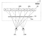
- FIG. 3 is a schematic diagram for explaining the parallax barrier method, and is a top view.
- the left-eye pixel row 40L and the right-eye pixel row 40R are alternately assigned to a plurality of pixel rows.
- the video element 40 is, for example, a reflective or transmissive element for a projector.
- a parallax barrier 50 is provided in front of the image element 40.
- “Before the image element 40” means between the image element 40 and the user 20.
- the left-eye image output from the left-eye pixel row 40 ⁇ / b> L enters the left eye 20 ⁇ / b> L of the user 20 through the slit 50 a provided in the parallax barrier 50.
- the right-eye image output from the right-eye pixel row 40R enters the right eye 20R of the user 20 through the slit 50a.
- the left-eye image output from the left-eye pixel row 40L is unlikely to enter the right eye 20R of the user 20 due to the parallax barrier 50, and the right-eye image output from the right-eye pixel row 40R.
- the image is unlikely to enter the left eye 20 ⁇ / b> L of the user 20 due to the parallax barrier 50.
- the projection unit 12 can project a 3D image that can be stereoscopically viewed by the user 20 with the naked eye.
- the projection unit 12 displays a 2D image
- the same image may be output from the left-eye pixel row 40L and the corresponding right-eye pixel row 40R.
- the projection unit 12 may project a 3D image by a lenticular method.
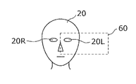
- FIG. 4 is a diagram for explaining a range in which a 3D image can be appropriately stereoscopically viewed.
- the predetermined range 60 is a rectangular area surrounded by a broken line in FIG. For this reason, the user 20 can appropriately stereoscopically view the 3D image.
- the predetermined range 60 is called, for example, an eye box, and has a height (vertical direction) of 40 mm and a width (horizontal direction) of about 130 mm.
- FIG. 5 is a flowchart for switching between a 2D image and a 3D image.
- FIGS. 6A to 6C and FIG. 7, which are diagrams showing the state of the positions of both eyes of the user 20, will be used.
- the detection unit 11 detects the position of both eyes (S11), and the control unit 13 determines whether the detection result of the detection unit 11 is a detection error (S12).
- the detection error means that the detection unit 11 fails to detect at least one of the positions of both eyes of the user 20.
- Examples of the detection error include a case where the hand of the user 20 covers the eyes of the user 20 (FIG. 6A) and a case where the image of the face of the user 20 is overexposed by external light.
- the control unit 13 When the detection result of the detection unit 11 is a detection error (Yes in S12), the control unit 13 causes the projection unit 12 to project a 2D image (S16). When the detection result of the detection unit 11 is not a detection error (No in S12), the control unit 13 determines whether at least one of the detected positions of both eyes of the user 20 is outside the predetermined range 60 (S13). .
- the control unit 13 When it is detected that at least one of the positions of both eyes of the user 20 is outside the predetermined range 60 (Yes in S13), the control unit 13 causes the projection unit 12 to project a 2D image (S16). When it is detected that the position of both eyes of the user 20 is not out of the predetermined range 60, that is, within the predetermined range 60 (No in S13), the control unit 13 determines the position of both eyes of the detected user 20 It is determined whether or not the height difference is greater than or equal to a predetermined value (S14).
- the predetermined value is a first predetermined value.
- the case where the difference in height between the positions of both eyes is equal to or greater than a predetermined value means that the difference in height between the positions of both eyes, for example, as shown in FIG. This is a case where L1 becomes large.
- the 3D image is projected in consideration of the distance between human eyes. Therefore, when it is detected that the height difference L1 between the positions of both eyes is large, that is, when it is detected that the horizontal interval between the positions of both eyes is small, the user 20 appropriately displays the 3D image in three-dimensional form. I can't see it.
- the control unit 13 When it is detected that the height difference L1 between the positions of both eyes of the user 20 is greater than or equal to a predetermined value (Yes in S14), the control unit 13 causes the projection unit 12 to project a 2D image (S16). When it is detected that the height difference L1 between the positions of both eyes of the user 20 is not greater than or equal to the predetermined value (ie, no in S14), the control unit 13 causes the projection unit 12 to project a 3D image. (S16).
- control unit 13 switches whether to project a 2D image or a 3D image on the projection unit 12 according to the detection result of the detection unit 11. Thereby, the display apparatus 10 can display a 3D image according to the situation of the user 20.
- the control unit 13 when it is detected that at least one of the positions of both eyes of the user 20 is outside the predetermined range 60, the control unit 13 causes the projection unit 12 to project a 2D image. However, when it is detected that at least one of the positions of both eyes of the user 20 is outside the predetermined range 60 and the horizontal distance between the positions of both eyes of the user 20 is less than a predetermined value, the control unit 13 may cause the projection unit 12 to project a 3D image.
- the predetermined value is a second predetermined value.
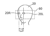
- the case where the horizontal distance between the positions of both eyes is less than a predetermined value means that the distance between the positions of both eyes in the horizontal direction, for example, when the user 20 faces sideways as shown in FIG. This is a case where L2 becomes small.
- the user 20 who drives the vehicle often turns to the side for driving to check the surrounding situation. In such a case, the position of both eyes of the user 20 may quickly return within the predetermined range 60. Many.
- the case where the user 20 is facing sideways is a case where the user 20 is not facing forward or the windshield 15. That is, even if a 3D image is projected, it is considered that the user 20 is not visually recognizing the 3D image, and it is unlikely that the user 20 cannot appropriately stereoscopically view the 3D image. Therefore, in such a case, even if at least one of the positions of both eyes of the user 20 is outside the predetermined range 60, the projection of the 3D image may be prioritized.
- FIG. 9 is a flowchart of switching between a 2D image and a 3D image in a case where switching is determined every predetermined period.
- the detection unit 11 detects the position of both eyes of the user 20 for each detection cycle (S22). And the control part 13 judges whether the detection result of the detection part 11 is a detection error (S23).
- the detection result of the detection unit 11 is a detection error (Yes in S23), whether a predetermined period has elapsed since the first detection error (from when the detection error occurred after the detection was successful) It is determined whether or not (S24). On the other hand, when the detection result is not a detection error in step S23 (No in S23), the position of both eyes of the user 20 is detected (S22).
- step S24 when a predetermined period has elapsed since the first detection error (Yes in S24), the control unit 13 causes the projection unit 12 to project a 2D image (S25). If a predetermined period has elapsed from the first detection error in step S24 (No in S24), the position of both eyes of the user 20 is detected (S22).
- the detection unit 11 succeeds in detecting the positions of both eyes for a predetermined period. If not, the control unit 13 may cause the projection unit 12 to project a 2D image.
- the display device 10 displays the 3D image according to the situation of the user 20. can do.
- the flowchart shown in FIG. 9 is based on whether or not the switching criterion is a detection error, and the case where a 3D image is switched to a 2D image is shown as an example.
- the determination criterion for switching is other than a detection error, or when a 2D image is switched to a 3D image, the determination of switching may be performed every predetermined period.
- the detection error may occur due to overexposure of an image captured by the detection unit 11 or a problem on the detection unit 11 side.
- the detection error does not necessarily indicate that the position of both eyes of the user 20 is a 3D image. The case where it cannot be said that is in an inappropriate position is included.
- the display device 10 basically projects a 3D image, the frequency of switching between the 2D image and the 3D image can be reduced.
- the currently projected image may be maintained. Specifically, if the detection result is a detection error when the 2D image is being projected, the 2D image is continuously projected, and the detection result is a detection error when the 3D image is being projected. In such a case, the 3D image may be continuously projected. According to such a configuration, the frequency of switching between the 2D image and the 3D image can be reduced.
- the first embodiment has been described as an example of the present disclosure.
- the present disclosure is not limited to this, and can also be applied to an embodiment in which changes, replacements, additions, omissions, and the like are appropriately made.
- the display device 10 projects an image on the windshield 15, but the display device 10 may project an image on a so-called combiner.
- FIG. 10 is a diagram illustrating an example of a display device that projects an image onto a combiner.
- the combiner 70 is an optical member having a concave structure, and the image projected on the combiner 70 is displayed larger than the windshield 15 when viewed from the user 20.
- the display device according to the above embodiment may project an image on a light-transmitting display medium other than the windshield 15 and the combiner 70.
- the display device according to the above embodiment may be provided in a moving body other than a vehicle, such as an airplane.
- a mirror is provided between image projectors, such as a liquid crystal panel, and a windshield glass.
- image projectors such as a liquid crystal panel
- a windshield glass such as a liquid crystal panel
- an optical system using a lens may be arranged.
- the detection unit 11 may detect the position and orientation of the user's head.
- the detection part 11 may detect a seating attitude
- each component may be configured by dedicated hardware or may be realized by executing a software program suitable for each component.
- Each component may be realized by a program execution unit such as a CPU or a processor reading and executing a software program recorded on a recording medium such as a hard disk or a semiconductor memory.
- the display device (display method) according to one or more aspects has been described based on the embodiment, but the present disclosure is not limited to this embodiment. Unless it deviates from the gist of the present disclosure, various modifications conceived by those skilled in the art have been made in this embodiment, and forms constructed by combining components in different embodiments are also within the scope of one or more aspects. May be included.
- another processing unit may execute a process executed by a specific processing unit.
- the order of the plurality of processes may be changed, and the plurality of processes may be executed in parallel.
- a display device includes a detection unit that detects the position of both eyes of the user, a projection unit that projects a 2D image and a 3D image that can be stereoscopically viewed by the user with the naked eye, and detection.
- a control unit that switches whether to project a 2D image or a 3D image on the projection unit according to the detection result of the unit.
- control unit may cause the projection unit to project a 2D image when the detection unit fails to detect at least one of the positions of both eyes.
- control unit may cause the projection unit to project a 2D image when the detection unit detects that at least one of the positions of both eyes is out of a predetermined range.
- control unit may cause the projection unit to project a 2D image when the detection unit detects that the height difference between the positions of both eyes is equal to or greater than a predetermined value.
- control unit determines that the projection unit detects that at least one of the positions of both eyes is out of a predetermined range and the detection unit detects that the horizontal distance between the positions of both eyes is less than a predetermined value.
- a 3D image may be projected.
- the control unit projects a 2D image on the projection unit when the detection unit fails to detect the position of both eyes within a predetermined period from when the detection of at least one of the positions of both eyes fails. You may let them.
- control unit may determine whether to switch to the projection of the 2D image according to the detection result of the detection unit when the projection unit projects the 3D image.
- the projection unit may project an image on a translucent display medium and allow the user to visually recognize the image reflected on the display medium.
- the display device may be a vehicle head-up display
- the projection unit may project an image on a windshield or a combiner.
- This disclosure is useful as a vehicle head-up display.
Abstract
表示装置は、検出部と、投射部と、制御部とを有する。検出部は、ユーザの両眼の位置を検出する。投射部は、2D画像、およびユーザが裸眼で立体視可能な3D画像を投射する。制御部は、検出部の検出結果に応じて、投射部に2D画像を投射させるか、3D画像を投射させるかを切り替える。
Description
本開示は、表示装置に関し、特に、車両用の表示装置に関する。
車両用の表示装置として、ヘッドアップディスプレイ(HUD)が知られている(例えば特許文献1参照)。ヘッドアップディスプレイでは、例えば、車両の状態を示すオブジェクトや、車両をナビゲートするためのオブジェクトが表示される。車両の状態を示すオブジェクトは、例えば、車両の速度情報を表現するものである。また、車両をナビゲートするためのオブジェクトは、例えば、矢印である。
本開示は、ユーザの状況に応じて3D画像を表示することができる表示装置を提供する。
本開示の一態様に係る表示装置は、表示装置は、検出部と、投射部と、制御部とを有する。検出部は、ユーザの両眼の位置を検出する。投射部は、2D画像、およびユーザが裸眼で立体視可能な3D画像を投射する。制御部は、検出部の検出結果に応じて、投射部に2D画像を投射させるか、3D画像を投射させるかを切り替える。
本開示の表示装置は、ユーザの状況に応じて3D画像を表示することができる。
表示装置の技術分野において、3D画像を表示する技術が知られている。しかしながら、ヘッドアップディスプレイのような車両用の表示装置では、ユーザの運転に支障をきたさないように状況に応じて3D画像が表示される必要がある。
以下、実施の形態について、図面を参照しながら具体的に説明する。
なお、以下で説明する実施の形態は、いずれも包括的または具体的な例を示すものである。以下の実施の形態で示される数値、形状、材料、構成要素、構成要素の配置位置および接続形態、ステップ、ステップの順序などは、一例であり、本開示を限定する主旨ではない。
(実施の形態1)
[構成]
まず、実施の形態1に係る表示装置の構成について説明する。図1は、実施の形態1に係る表示装置の機能構成を示すブロック図である。図2は、実施の形態1に係る表示装置の構成を示す模式図である。
[構成]
まず、実施の形態1に係る表示装置の構成について説明する。図1は、実施の形態1に係る表示装置の機能構成を示すブロック図である。図2は、実施の形態1に係る表示装置の構成を示す模式図である。
図1に示されるように、表示装置10は、検出部11と、投射部12と、制御部13と取得部14とを有する。表示装置10は、いわゆるヘッドアップディスプレイであり、図2に示されるように車室内に設けられる。表示装置10(投射部12)は、風防ガラス15に画像を投射し、風防ガラス15において反射された画像をユーザ20に視認させる。なお、風防ガラス15は、例えば、フロントガラスである。
検出部11は、ユーザ20の両眼の位置を検出する。検出部11は、具体的には、例えば、少なくともユーザ20の顔面を撮影する撮像部と、撮影された画像を用いてのユーザ20の両眼の位置を検出する処理部とからなる。つまり、検出部11は、ユーザ20の顔面を正面から撮影するとともに、撮影した画像を用いてユーザ20の両眼の位置を検出する。なお、両眼の位置の検出には、既存の顔認識技術など、どのような方法が用いられてもよい。また、検出部11の両眼の位置の検出は、例えば、1秒間に30~60回程度行われる。撮像部は撮像装置であってもよい。
投射部12は、2D画像およびユーザ20が裸眼で立体視可能な3D画像を投射することができる画像投射装置である。投射部12は、実施の形態1では、投射部12は、タブレット状の画像投射装置であり、例えば、図2に示されるように車両のダッシュボードに取り付けられる。
投射部12は、風防ガラス15に向けて光を投射し、風防ガラス15における反射を利用して位置30に画像を結像させることができる。ここで結像される画像は虚像である。つまり、投射部12から2D画像が投射される場合、2D画像は、位置30に表示される。2D画像とは、2D画像を構成する光である。
一方で、投射部12から3D画像が投射される場合も、3D画像は位置30に表示される。3D画像とは、3D画像を構成する光である。しかしながら、3D画像が投射される場合は、ユーザ20の左眼によって視認される画像と、右眼によって視認される画像とは、視差を有する互いに異なる画像である。なお、左眼によって視認される画像を左眼用画像、右眼によって視認される画像を右眼用画像ともいう。このため、投射部12から3D画像が投射される場合、当該3D画像に含まれる各オブジェクトは、当該オブジェクトの視差に応じて、手前側の位置30aや、奥側の位置30bなどに知覚される。
投射部12の画像の投射は、具体的には、反射型液晶およびLEDを使用したLCOS方式、マイクロミラーアレイおよびLEDを使用したDLP(登録商標)方式、MEMSミラーおよび半導体レーザを使用したレーザ走査方式などによって実現される。レーザ走査方式は、例えば、ラスタースキャン方式である。なお、投射部12が投射する3D画像は、裸眼で立体視可能な画像であり、これについての詳細は後述する。
取得部14は、車両から当該車両に関する情報を取得する。車両に関する情報は、具体的には、車速情報などである。なお、取得部14は、スマートフォンや、車両内に設けられたカーナビゲーション装置など、表示装置10とは異なる装置から情報を取得してもよい。なお、取得部14の情報の取得には、有線または無線のどのような通信ネットワークが用いられてもよい。通信ネットワークは、通信インターフェースでもよい。
制御部13は、検出部11の検出結果に応じて投射部12に2D画像を投射させるか3D画像を投射させるかを切り替える。制御部13の画像の切り替えの詳細については後述する。制御部13は、例えば、取得部14が取得した情報に基づいて、ナビゲーション用の矢印を含む画像や、スピードメータを含む画像などを投射させる。
制御部13は、具体的には、プロセッサである。なお、制御部13は、ハードウェアのみで構成されてもよいし、ハードウェアとソフトウェアとを組み合わせることにより実現されてもよい。制御部13は、例えば、マイコンなどでも実現できる。
[3D画像の投射方法]
次に、ユーザ20が裸眼で立体視可能な3D画像の投射方法について説明する。投射部12は、例えば、視差バリア方式で3D画像を投射する。図3は、視差バリア方式を説明するための模式図であり、上面図である。
次に、ユーザ20が裸眼で立体視可能な3D画像の投射方法について説明する。投射部12は、例えば、視差バリア方式で3D画像を投射する。図3は、視差バリア方式を説明するための模式図であり、上面図である。
図3に示されるように、視差バリア方式では、映像素子40において、複数の画素列に対して、左眼用の画素列40Lと右眼用の画素列40Rとが交互に割り当てられる。映像素子40は、例えば、プロジェクタ用の反射型または透過型の素子である。
また、映像素子40の前には、視差バリア50が設けられる。映像素子40の前とは、映像素子40とユーザ20との間を意味する。左眼用の画素列40Lから出力される左眼用画像は、視差バリア50に設けられたスリット50aを通ってユーザ20の左眼20Lに入射する。同様に、右眼用の画素列40Rから出力される右眼用画像は、スリット50aを通ってユーザ20の右眼20Rに入射する。一方で、左眼用の画素列40Lから出力される左眼用画像は、視差バリア50によってユーザ20の右眼20Rには入射しにくく、右眼用の画素列40Rから出力される右眼用画像は、視差バリア50によってユーザ20の左眼20Lには入射しにくい。
以上のような構成により、投射部12は、ユーザ20が裸眼で立体視可能な3D画像を投射することができる。なお、投射部12が2D画像を表示する場合には、左眼用の画素列40Lと、これに対応する右眼用の画素列40Rとから同じ画像が出力されればよい。
なお、投射部12は、レンチキュラ方式で3D画像の投射を行ってもよい。
[3D画像と2D画像の切り替え]
上述のような3D画像の投射においては、運転席におけるユーザ20の両眼の位置を想定し、想定した両眼の位置に左眼用画像および右眼用画像が入射するように光学設計がなされる。したがって、ユーザ20の両眼の位置が所定の範囲内に無ければ、ユーザ20は、3D画像を適切に立体視できない。図4は、3D画像を適切に立体視できる範囲を説明するための図である。
上述のような3D画像の投射においては、運転席におけるユーザ20の両眼の位置を想定し、想定した両眼の位置に左眼用画像および右眼用画像が入射するように光学設計がなされる。したがって、ユーザ20の両眼の位置が所定の範囲内に無ければ、ユーザ20は、3D画像を適切に立体視できない。図4は、3D画像を適切に立体視できる範囲を説明するための図である。
ユーザ20の眼が所定の範囲60に位置するときには、左眼用画像が左眼20Lに入射し、右眼用画像が右眼20Rに入射する。なお、所定の範囲60は、図4の破線で囲まれた矩形の領域である。このため、ユーザ20は、3D画像を適切に立体視できる。なお、所定の範囲60は、例えば、アイボックスなどと呼ばれ、高さ(垂直方向)40mm、幅(水平方向)130mm程度の大きさである。
しかしながら、ユーザ20の少なくとも一方の眼が所定の範囲60の外に位置するときは、ユーザ20は、3D画像を適切に立体視できない。
表示装置10のような車両用の表示装置において3D画像が表示される場合、ユーザ20が運転中に姿勢を変えるなどして3D画像を適切に立体視できなくなると、ユーザ20の運転に支障をきたす場合があり、危険である。
そこで、表示装置10の制御部13は、2D画像と3D画像との切り替えを行う。図5は、2D画像と3D画像との切り替えのフローチャートである。なお、以下では、図5に加えて、ユーザ20の両眼の位置の状態を示す図である図6A~図6Cおよび図7の各図面が説明に用いられる。
検出部11は、両眼の位置を検出し(S11)、制御部13は、検出部11の検出結果が検出エラーであるかを判断する(S12)。
ここで、検出エラーは、検出部11がユーザ20の両眼の位置の少なくとも一方の検出に失敗することを意味する。検出エラーとなる場合には、例えば、ユーザ20の手がユーザ20の眼を覆う場合(図6A)や、外光によりユーザ20の顔面の画像が白とびしてしまうような場合が含まれる。
検出部11の検出結果が検出エラーである場合(S12でYes)、制御部13は、投射部12に2D画像を投射させる(S16)。検出部11の検出結果が検出エラーでない場合(S12でNo)、制御部13は、検出されたユーザ20の両眼の位置の少なくとも一方が所定の範囲60外であるかを判断する(S13)。
ここで、両眼の位置の少なくとも一方が所定の範囲60外である場合には、例えば、ユーザ20の頭部が横方向(水平方向)にずれている場合(図6B)や、ユーザ20の頭部が縦方向(高さ方向)にずれている場合(図6C)などが含まれる。
ユーザ20の両眼の位置の少なくとも一方が所定の範囲60外であると検出された場合(S13でYes)、制御部13は、投射部12に2D画像を投射させる(S16)。ユーザ20の両眼の位置が所定の範囲60外でない、すなわち所定の範囲60内であると検出された場合(S13でNo)、制御部13は、検出されたユーザ20の両眼の位置の高さの差が所定値以上であるか否かを判断する(S14)。ここで所定値は、第1の所定値である。
ここで、両眼の位置の高さの差が所定値以上である場合とは、例えば、図7に示されるようにユーザ20が首をかしげるなどして、両眼の位置の高さの差L1が大きくなった場合である。3D画像は、人間の両眼の間隔を考慮して投射される。このため、両眼の位置の高さの差L1が大きいと検出される場合、すなわち両眼の位置の水平方向の間隔が小さいと検出される場合は、ユーザ20は、3D画像を適切に立体視することができない。
ユーザ20の両眼の位置の高さの差L1が所定値以上であると検出された場合(S14でYes)、制御部13は、投射部12に2D画像を投射させる(S16)。ユーザ20の両眼の位置の高さの差L1が所定値以上でない、すなわち所定値未満であると検出された場合(S14でNo)、制御部13は、投射部12に3D画像を投射させる(S16)。
以上説明したように、制御部13は、検出部11の検出結果に応じて投射部12に2D画像を投射させるか3D画像を投射させるかを切り替える。これにより、表示装置10は、ユーザ20の状況に応じて3D画像を表示することができる。
なお、図5のフローチャートにおいて、ステップの一部は省略されてもよいし、ステップの順序が入れ替えられてもよい。また、図5のフローチャートにおいて一部のステップが並列に処理されてもよい。
[変形例1]
上記実施の形態1では、ユーザ20の両眼の位置の少なくとも一方が所定の範囲60外であると検出された場合は、制御部13は、投射部12に2D画像を投射させるとした。しかしながら、ユーザ20の両眼の位置の少なくとも一方が所定の範囲60外であると検出され、かつ、ユーザ20の両眼の位置の水平方向の距離が所定値未満である場合には、制御部13は、投射部12に3D画像を投射させてもよい。ここで、所定値は第2の所定値である。
上記実施の形態1では、ユーザ20の両眼の位置の少なくとも一方が所定の範囲60外であると検出された場合は、制御部13は、投射部12に2D画像を投射させるとした。しかしながら、ユーザ20の両眼の位置の少なくとも一方が所定の範囲60外であると検出され、かつ、ユーザ20の両眼の位置の水平方向の距離が所定値未満である場合には、制御部13は、投射部12に3D画像を投射させてもよい。ここで、所定値は第2の所定値である。
ここで、両眼の位置の水平方向の距離が所定値未満である場合とは、例えば、図8に示されるようにユーザ20が横を向くなどして、両眼の位置の水平方向の距離L2が小さくなった場合である。
車両を運転するユーザ20は、周辺状況の確認などのために運転時に横を向くことが多いが、このような場合、すぐにユーザ20の両眼の位置は所定の範囲60内に戻ることが多い。
また、ユーザ20が横を向いている場合とは、すなわち、ユーザ20が前方、または風防ガラス15の方向を向いていない場合である。つまり、3D画像が投射されていても、ユーザ20は当該3D画像を視認しておらず、ユーザ20が3D画像を適切に立体視できない可能性は低いと考えられる。したがって、このような場合には、ユーザ20の両眼の位置の少なくとも一方が所定の範囲60外であっても、3D画像の投射が優先されてもよい。
[変形例2]
また、上記実施の形態1において説明した3D画像の投射と2D画像の投射との切り替えが頻繁に行われると、ユーザ20の運転の妨げとなってしまうことも考えられる。そこで、切り替えの頻度を下げるために、切り替えの判断は、検出部11の両眼の位置の検出期間よりも長い所定の期間ごとに行われてもよい。図9は、切り替えの判断が所定の期間ごとに行われる場合の2D画像と3D画像との切り替えのフローチャートである。
また、上記実施の形態1において説明した3D画像の投射と2D画像の投射との切り替えが頻繁に行われると、ユーザ20の運転の妨げとなってしまうことも考えられる。そこで、切り替えの頻度を下げるために、切り替えの判断は、検出部11の両眼の位置の検出期間よりも長い所定の期間ごとに行われてもよい。図9は、切り替えの判断が所定の期間ごとに行われる場合の2D画像と3D画像との切り替えのフローチャートである。
図9に示されるように、投射部12が3D画像を投射しているときに(S21)、検出部11は、検出周期ごとにユーザ20の両眼の位置の検出を行う(S22)。そして、制御部13は、検出部11の検出結果が検出エラーであるかを判断する(S23)。
検出部11の検出結果が検出エラーである場合には(S23でYes)、最初の検出エラーから(検出に成功していた状態から検出エラーになったときから)所定の期間が経過しているか否かを判断する(S24)。一方で、ステップS23で検出結果が検出エラーでない場合は(S23でNo)、ユーザ20の両眼の位置の検出が行われる(S22)。
ステップS24において、最初の検出エラーから所定の期間が経過している場合には(S24でYes)、制御部13は、投射部12に2D画像を投射させる(S25)。ステップS24で最初の検出エラーから所定の期間が経過している場合は(S24でNo)、ユーザ20の両眼の位置の検出が行われる(S22)。
このように、検出エラーが所定の期間続いた場合、つまり、ユーザ20の両眼の位置の少なくとも一方の検出に失敗したときから所定の期間、検出部11が両眼の位置の検出に成功しなかった場合に、制御部13は、投射部12に2D画像を投射させてもよい。
以上のような構成によれば、これにより、3D画像の投射と2D画像の投射とが頻繁に切り替えられることが抑制されるため、表示装置10は、ユーザ20の状況に応じて3D画像を表示することができる。
なお、図9に示されるフローチャートは、切り替えの判断基準が検出エラーであるか否かであり、かつ、3D画像を2D画像に切り替える場合を示すが、このフローチャートは、一例である。切り替えの判断基準が検出エラー以外である場合や、2D画像を3D画像に切り替える場合に、切り替えの判断が所定の期間ごとに行われてもよい。
[変形例3]
上記実施の形態1では、検出結果が検出エラーである場合には2D画像が投射されるとして説明したが、検出結果が検出エラーである場合には、3D画像が投射されてもよい。
上記実施の形態1では、検出結果が検出エラーである場合には2D画像が投射されるとして説明したが、検出結果が検出エラーである場合には、3D画像が投射されてもよい。
上述のように、検出エラーは、検出部11が撮影する画像の白とびや、検出部11側の不具合により生じる可能性があり、検出エラーには、必ずしもユーザ20の両眼の位置が3D画像に不適切な位置にあるといえない場合が含まれる。このような構成によれば、表示装置10が基本的に3D画像を投射する場合に、2D画像と3D画像との切り替えの頻度を減らすことができる。
また、検出結果が検出エラーである場合には、現在投射中の画像が維持されてもよい。具体的には、2D画像が投射されているときに検出結果が検出エラーとなった場合には、2D画像が継続して投射され、3D画像が投射されているときに検出結果が検出エラーとなった場合には、3D画像が継続して投射されてもよい。このような構成によれば、2D画像と3D画像との切り替えの頻度を減らすことができる。
(その他の実施の形態)
以上のように、本開示の例示として、実施の形態1を説明した。しかしながら、本開示は、これに限定されず、適宜、変更、置き換え、付加、省略などを行った実施の形態にも適用可能である。また、上記実施の形態1で説明した各構成要素を組み合わせて、新たな実施の形態とすることも可能である。
以上のように、本開示の例示として、実施の形態1を説明した。しかしながら、本開示は、これに限定されず、適宜、変更、置き換え、付加、省略などを行った実施の形態にも適用可能である。また、上記実施の形態1で説明した各構成要素を組み合わせて、新たな実施の形態とすることも可能である。
例えば、上記実施の形態では、表示装置10は、風防ガラス15に画像を投射したが、表示装置10は、いわゆるコンバイナーに画像を投射してもよい。図10は、コンバイナーに画像を投射する表示装置の一例を示す図である。
図10に示される表示装置10aは、コンバイナー70に画像を投射する。ここで、コンバイナー70は、凹面構造の光学部材であり、コンバイナー70に投射された画像は、ユーザ20から見て風防ガラス15よりも遠くに大きく表示される。
また、上記実施の形態に係る表示装置は、風防ガラス15およびコンバイナー70以外の透光性を有する表示媒体に画像を投射してもよい。また、上記実施の形態に係る表示装置は、車両以外の移動体、例えば、飛行機などに設けられてもよい。
また、上記実施の形態では、上記実施の形態に係る表示装置を、タブレット状の画像投射装置を用いた例で説明したが、液晶パネルのような画像投射装置と風防ガラスとの間に、ミラーやレンズを用いた光学系を配する構成にしてもよい。
また、上記実施の形態では、検出部11が両眼の位置を検出する例を用いて説明したが、検出部はユーザの頭部の位置や向きを検出してもよい。また、検出部11は、ユーザの着座するシートに配された圧力センサなどによって着座姿勢を検出してもよい。これらの例では検出部11が安価で小型に構成できる効果がある。
また、上記実施の形態において、各構成要素は、専用のハードウェアで構成されるか、各構成要素に適したソフトウェアプログラムを実行することによって実現されてもよい。各構成要素は、CPUまたはプロセッサなどのプログラム実行部が、ハードディスクまたは半導体メモリなどの記録媒体に記録されたソフトウェアプログラムを読み出して実行することによって実現されてもよい。
以上、一つまたは複数の態様に係る表示装置(表示方法)について、実施の形態に基づいて説明したが、本開示は、この実施の形態に限定されるものではない。本開示の趣旨を逸脱しない限り、当業者が思いつく各種変形を本実施の形態に施したものや、異なる実施の形態における構成要素を組み合わせて構築される形態も、一つまたは複数の態様の範囲内に含まれてもよい。
例えば、上記各実施の形態において、特定の処理部が実行する処理を別の処理部が実行してもよい。また、複数の処理の順序が変更されてもよいし、複数の処理が並行して実行されてもよい。
以上のように、本開示の一態様に係る表示装置は、ユーザの両眼の位置を検出する検出部と、2D画像およびユーザが裸眼で立体視可能な3D画像を投射する投射部と、検出部の検出結果に応じて投射部に2D画像を投射させるか3D画像を投射させるかを切り替える制御部とを有する。
また、制御部は、検出部が両眼の位置の少なくとも一方の検出に失敗した場合に、投射部に2D画像を投射させてもよい。
また、制御部は、検出部が両眼の位置の少なくとも一方が所定の範囲外であると検出した場合に、投射部に2D画像を投射させてもよい。
また、制御部は、検出部が両眼の位置の高さの差が所定値以上であると検出した場合に、投射部に2D画像を投射させてもよい。
また、制御部は、両眼の位置の少なくとも一方が所定の範囲外であり、かつ、検出部が両眼の位置の水平方向の距離が所定値未満であると検出した場合に、投射部に3D画像を投射させてもよい。
また、制御部は、検出部が、両眼の位置の少なくとも一方の検出に失敗したときから所定の期間内に両眼の位置の検出に成功しなかった場合に、投射部に2D画像を投射させてもよい。
また、制御部は、投射部に3D画像を投射させているときに、2D画像の投射に切り替えるか否かを検出部の検出結果に応じて決定してもよい。
また、投射部は、透光性を有する表示媒体に画像を投射し、表示媒体において反射された画像をユーザに視認させてもよい。
また表示装置は、車載用ヘッドアップディスプレイであり、投射部は、風防ガラスまたはコンバイナーに画像を投射してもよい。
なお、これらの全般的または具体的な態様は、システム、装置、集積回路、またはコンピュータプログラムまたは記録媒体で実現されてもよい。また、これらの全般的または具体的な態様は、システム、装置、集積回路、およびコンピュータプログラムおよび記録媒体の任意な組み合わせで実現されてもよい。
本開示は、車載用のヘッドアップディスプレイとして有用である。
10,10a 表示装置
11 検出部
12 投射部
13 制御部
14 取得部
15 風防ガラス
20 ユーザ
20L 左眼
20R 右眼
30,30a,30b 位置
40 映像素子
40L 左眼用の画素列
40R 右眼用の画素列
50 視差バリア
50a スリット
60 所定の範囲
70 コンバイナー
11 検出部
12 投射部
13 制御部
14 取得部
15 風防ガラス
20 ユーザ
20L 左眼
20R 右眼
30,30a,30b 位置
40 映像素子
40L 左眼用の画素列
40R 右眼用の画素列
50 視差バリア
50a スリット
60 所定の範囲
70 コンバイナー
Claims (11)
- ユーザの両眼の位置を検出する検出部と、
2D画像および前記ユーザが裸眼で立体視可能な3D画像を投射する投射部と、
前記検出部の検出結果に応じて前記投射部に前記2D画像を投射させるか前記3D画像を投射させるかを切り替える制御部と、を備えた、
表示装置。 - 前記制御部は、前記検出部が前記両眼の位置の少なくとも一方の検出に失敗した場合に、前記投射部に前記2D画像を投射させる、
請求項1に記載の表示装置。 - 前記制御部は、前記検出部が前記両眼の位置の少なくとも一方が所定の範囲外であると検出した場合に、前記投射部に前記2D画像を投射させる、
請求項1、2のいずれか一項に記載の表示装置。 - 前記制御部は、前記検出部が前記両眼の位置の高さの差が所定値以上であると検出した場合に、前記投射部に前記2D画像を投射させる、
請求項1~3のいずれか一項に記載の表示装置。 - 前記制御部は、前記両眼の位置の少なくとも一方が所定の範囲外であり、かつ、前記検出部が前記両眼の位置の水平方向の距離が所定値未満であると検出した場合に、前記投射部に前記3D画像を投射させる、
請求項1~4のいずれか一項に記載の表示装置。 - 前記制御部は、前記検出部が、前記両眼の位置の少なくとも一方の検出に失敗したときから所定の期間内に前記両眼の位置の検出に成功しなかった場合に、前記投射部に前記2D画像を投射させる、
請求項2に記載の表示装置。 - 前記制御部は、前記投射部に前記3D画像を投射させているときに、前記2D画像の投射に切り替えるか否かを前記検出部の検出結果に応じて決定する、
請求項1に記載の表示装置。 - 前記投射部は、透光性を有する表示媒体に画像を投射し、前記表示媒体において反射された前記画像を前記ユーザに視認させる、
請求項1~7のいずれか一項に記載の表示装置。 - 前記表示装置は、車載用ヘッドアップディスプレイであり、
前記投射部は、風防ガラスまたはコンバイナーに前記画像を投射する、
請求項8に記載の表示装置。 - ユーザの両眼の位置を検出し、
前記検出の結果に応じて、2D画像を投射するか前記ユーザが裸眼で立体視可能な3D画像を投射するかを切り替える、
表示方法。 - 請求項10に記載の表示方法をコンピュータに実行させるためのプログラム。
Priority Applications (2)
| Application Number | Priority Date | Filing Date | Title |
|---|---|---|---|
| EP15793204.7A EP3145185A4 (en) | 2014-05-12 | 2015-05-08 | Display device and display method |
| US15/306,068 US20170046880A1 (en) | 2014-05-12 | 2015-05-08 | Display device and display method |
Applications Claiming Priority (2)
| Application Number | Priority Date | Filing Date | Title |
|---|---|---|---|
| JP2014-098767 | 2014-05-12 | ||
| JP2014098767A JP2015215505A (ja) | 2014-05-12 | 2014-05-12 | 表示装置、および表示方法 |
Publications (1)
| Publication Number | Publication Date |
|---|---|
| WO2015174051A1 true WO2015174051A1 (ja) | 2015-11-19 |
Family
ID=54479602
Family Applications (1)
| Application Number | Title | Priority Date | Filing Date |
|---|---|---|---|
| PCT/JP2015/002338 WO2015174051A1 (ja) | 2014-05-12 | 2015-05-08 | 表示装置、および表示方法 |
Country Status (4)
| Country | Link |
|---|---|
| US (1) | US20170046880A1 (ja) |
| EP (1) | EP3145185A4 (ja) |
| JP (1) | JP2015215505A (ja) |
| WO (1) | WO2015174051A1 (ja) |
Cited By (1)
| Publication number | Priority date | Publication date | Assignee | Title |
|---|---|---|---|---|
| US10410427B2 (en) | 2016-03-24 | 2019-09-10 | Toyota Jidosha Kabushiki Kaisha | Three dimensional graphical overlays for a three dimensional heads-up display unit of a vehicle |
Families Citing this family (18)
| Publication number | Priority date | Publication date | Assignee | Title |
|---|---|---|---|---|
| KR101771944B1 (ko) * | 2016-04-19 | 2017-08-28 | 엘지전자 주식회사 | 차량용 디스플레이 장치 및 그 제어방법 |
| CN106004443B (zh) * | 2016-06-23 | 2019-12-10 | 广州亿程交通信息有限公司 | 用于车辆行驶方向提示的全息投影系统及投影方法 |
| JP6688211B2 (ja) * | 2016-12-07 | 2020-04-28 | 京セラ株式会社 | 光源装置、ディスプレイ装置、および移動体 |
| EP3554068B1 (en) * | 2016-12-07 | 2022-05-18 | Kyocera Corporation | Image projection apparatus |
| CN110073658B (zh) * | 2016-12-07 | 2022-04-22 | 京瓷株式会社 | 图像投影装置、图像显示装置以及移动体 |
| JP6688212B2 (ja) * | 2016-12-07 | 2020-04-28 | 京セラ株式会社 | 画像投影装置、画像表示装置、および移動体 |
| JP6799507B2 (ja) * | 2017-07-05 | 2020-12-16 | 京セラ株式会社 | 3次元投影装置、3次元投影システム、および移動体 |
| JP6688213B2 (ja) * | 2016-12-07 | 2020-04-28 | 京セラ株式会社 | 画像投影装置、画像表示装置、および移動体 |
| JP2019102936A (ja) * | 2017-11-30 | 2019-06-24 | シャープ株式会社 | 表示装置、電子ミラー、表示装置の制御方法、および表示制御プログラム |
| JP2019102935A (ja) * | 2017-11-30 | 2019-06-24 | シャープ株式会社 | 表示装置、電子ミラー、表示装置の制御方法、および表示制御プログラム |
| KR102531313B1 (ko) * | 2018-09-04 | 2023-05-12 | 현대자동차주식회사 | 디스플레이 장치, 그를 가지는 차량 및 그 제어 방법 |
| JP7105173B2 (ja) * | 2018-11-02 | 2022-07-22 | 京セラ株式会社 | 3次元表示装置、ヘッドアップディスプレイ、移動体、およびプログラム |
| JP7034052B2 (ja) * | 2018-11-02 | 2022-03-11 | 京セラ株式会社 | 無線通信ヘッドアップディスプレイシステム、無線通信機器、移動体、およびプログラム |
| JP7317517B2 (ja) | 2019-02-12 | 2023-07-31 | 株式会社ジャパンディスプレイ | 表示装置 |
| WO2021010123A1 (ja) * | 2019-07-17 | 2021-01-21 | 株式会社Jvcケンウッド | ヘッドアップディスプレイ装置 |
| WO2021200914A1 (ja) * | 2020-03-31 | 2021-10-07 | 日本精機株式会社 | 表示制御装置、ヘッドアップディスプレイ装置、及び方法 |
| CN113949862A (zh) * | 2021-09-08 | 2022-01-18 | 西安诺瓦星云科技股份有限公司 | 3d画面显示测试方法和装置以及显示控制设备和系统 |
| WO2023048213A1 (ja) * | 2021-09-23 | 2023-03-30 | 日本精機株式会社 | 表示制御装置、ヘッドアップディスプレイ装置、及び表示制御方法 |
Citations (4)
| Publication number | Priority date | Publication date | Assignee | Title |
|---|---|---|---|---|
| JP2001296501A (ja) * | 2000-04-12 | 2001-10-26 | Nippon Hoso Kyokai <Nhk> | 立体画像表示制御方法および装置 |
| JP2009250987A (ja) * | 2008-04-01 | 2009-10-29 | Casio Hitachi Mobile Communications Co Ltd | 画像表示装置およびプログラム |
| JP2012507183A (ja) * | 2008-10-28 | 2012-03-22 | コーニンクレッカ フィリップス エレクトロニクス エヌ ヴィ | 三次元表示システム |
| JP2014010418A (ja) * | 2012-07-03 | 2014-01-20 | Yazaki Corp | 立体表示装置及び立体表示方法 |
Family Cites Families (7)
| Publication number | Priority date | Publication date | Assignee | Title |
|---|---|---|---|---|
| US8101860B1 (en) * | 2007-06-20 | 2012-01-24 | Taymac Corporation | Electrical device cover |
| JP5494284B2 (ja) * | 2010-06-24 | 2014-05-14 | ソニー株式会社 | 立体表示装置及び立体表示装置の制御方法 |
| CN103380625A (zh) * | 2011-06-16 | 2013-10-30 | 松下电器产业株式会社 | 头戴式显示器及其位置偏差调整方法 |
| US9465226B2 (en) * | 2011-08-09 | 2016-10-11 | Sony Computer Entertainment Inc. | Automatic shutdown of 3D based on glasses orientation |
| MX2014012616A (es) * | 2012-04-24 | 2015-01-15 | Koninkl Philips Nv | Dispositivo de pantalla autoestereoscopica y metodo de excitacion. |
| JP6189423B2 (ja) * | 2012-05-18 | 2017-08-30 | リアルディー スパーク エルエルシー | 指向性光源用制御システム |
| US9118911B2 (en) * | 2013-02-07 | 2015-08-25 | Delphi Technologies, Inc. | Variable disparity three-dimensional (3D) display system and method of operating the same |
-
2014
- 2014-05-12 JP JP2014098767A patent/JP2015215505A/ja active Pending
-
2015
- 2015-05-08 US US15/306,068 patent/US20170046880A1/en not_active Abandoned
- 2015-05-08 EP EP15793204.7A patent/EP3145185A4/en not_active Withdrawn
- 2015-05-08 WO PCT/JP2015/002338 patent/WO2015174051A1/ja active Application Filing
Patent Citations (4)
| Publication number | Priority date | Publication date | Assignee | Title |
|---|---|---|---|---|
| JP2001296501A (ja) * | 2000-04-12 | 2001-10-26 | Nippon Hoso Kyokai <Nhk> | 立体画像表示制御方法および装置 |
| JP2009250987A (ja) * | 2008-04-01 | 2009-10-29 | Casio Hitachi Mobile Communications Co Ltd | 画像表示装置およびプログラム |
| JP2012507183A (ja) * | 2008-10-28 | 2012-03-22 | コーニンクレッカ フィリップス エレクトロニクス エヌ ヴィ | 三次元表示システム |
| JP2014010418A (ja) * | 2012-07-03 | 2014-01-20 | Yazaki Corp | 立体表示装置及び立体表示方法 |
Non-Patent Citations (1)
| Title |
|---|
| See also references of EP3145185A4 * |
Cited By (1)
| Publication number | Priority date | Publication date | Assignee | Title |
|---|---|---|---|---|
| US10410427B2 (en) | 2016-03-24 | 2019-09-10 | Toyota Jidosha Kabushiki Kaisha | Three dimensional graphical overlays for a three dimensional heads-up display unit of a vehicle |
Also Published As
| Publication number | Publication date |
|---|---|
| JP2015215505A (ja) | 2015-12-03 |
| EP3145185A1 (en) | 2017-03-22 |
| US20170046880A1 (en) | 2017-02-16 |
| EP3145185A4 (en) | 2017-05-10 |
Similar Documents
| Publication | Publication Date | Title |
|---|---|---|
| WO2015174051A1 (ja) | 表示装置、および表示方法 | |
| JP6410167B2 (ja) | 表示装置及びその表示方法 | |
| US10313666B2 (en) | Display device and display method | |
| JP4686586B2 (ja) | 車載用表示装置及び表示方法 | |
| JP2015210297A (ja) | 立体画像表示装置,立体画像表示方法,及び立体画像表示プログラム | |
| JP6279768B2 (ja) | 車両用情報表示装置 | |
| US20140320952A1 (en) | Head-Up Display Device | |
| US9684166B2 (en) | Motor vehicle and display of a three-dimensional graphical object | |
| JP2014068331A (ja) | 立体表示装置及びその表示方法 | |
| JP2016147532A (ja) | 画像生成装置、ヘッドアップディスプレイ | |
| WO2018124299A1 (ja) | 虚像表示装置及び方法 | |
| JP6515796B2 (ja) | ヘッドアップディスプレイ装置 | |
| JP2019120891A (ja) | 虚像表示装置、およびヘッドアップディスプレイ装置 | |
| WO2023228770A1 (ja) | 画像表示装置 | |
| JP2019191368A (ja) | 虚像表示装置、およびヘッドアップディスプレイ装置 | |
| WO2023228752A1 (ja) | 画像表示装置 | |
| WO2023228771A1 (ja) | 画像表示装置、車両及び画像表示方法 | |
| JP2015026024A (ja) | 立体画像観察装置、プロジェクタおよびプロジェクタシステム | |
| JP7253719B2 (ja) | 表示装置を備える車両 | |
| JPWO2018199244A1 (ja) | 表示システム | |
| WO2022230824A1 (ja) | 映像表示装置および映像表示方法 | |
| JP7257623B2 (ja) | 表示制御装置および表示制御方法 | |
| WO2023233919A1 (ja) | 画像投影システム | |
| WO2019124323A1 (ja) | 虚像表示装置、およびヘッドアップディスプレイ装置 | |
| WO2018216552A1 (ja) | ヘッドアップディスプレイ装置 |
Legal Events
| Date | Code | Title | Description |
|---|---|---|---|
| 121 | Ep: the epo has been informed by wipo that ep was designated in this application |
Ref document number: 15793204 Country of ref document: EP Kind code of ref document: A1 |
|
| REEP | Request for entry into the european phase |
Ref document number: 2015793204 Country of ref document: EP |
|
| WWE | Wipo information: entry into national phase |
Ref document number: 2015793204 Country of ref document: EP |
|
| WWE | Wipo information: entry into national phase |
Ref document number: 15306068 Country of ref document: US |
|
| NENP | Non-entry into the national phase |
Ref country code: DE |