WO2015170750A1 - モールドの洗浄システム - Google Patents
モールドの洗浄システム Download PDFInfo
- Publication number
- WO2015170750A1 WO2015170750A1 PCT/JP2015/063335 JP2015063335W WO2015170750A1 WO 2015170750 A1 WO2015170750 A1 WO 2015170750A1 JP 2015063335 W JP2015063335 W JP 2015063335W WO 2015170750 A1 WO2015170750 A1 WO 2015170750A1
- Authority
- WO
- WIPO (PCT)
- Prior art keywords
- mold
- laser
- molding surface
- laser head
- cleaning
- Prior art date
Links
Images

Classifications
-
- B—PERFORMING OPERATIONS; TRANSPORTING
- B29—WORKING OF PLASTICS; WORKING OF SUBSTANCES IN A PLASTIC STATE IN GENERAL
- B29D—PRODUCING PARTICULAR ARTICLES FROM PLASTICS OR FROM SUBSTANCES IN A PLASTIC STATE
- B29D30/00—Producing pneumatic or solid tyres or parts thereof
- B29D30/06—Pneumatic tyres or parts thereof (e.g. produced by casting, moulding, compression moulding, injection moulding, centrifugal casting)
- B29D30/0601—Vulcanising tyres; Vulcanising presses for tyres
- B29D30/0662—Accessories, details or auxiliary operations
-
- B—PERFORMING OPERATIONS; TRANSPORTING
- B08—CLEANING
- B08B—CLEANING IN GENERAL; PREVENTION OF FOULING IN GENERAL
- B08B7/00—Cleaning by methods not provided for in a single other subclass or a single group in this subclass
- B08B7/0035—Cleaning by methods not provided for in a single other subclass or a single group in this subclass by radiant energy, e.g. UV, laser, light beam or the like
- B08B7/0042—Cleaning by methods not provided for in a single other subclass or a single group in this subclass by radiant energy, e.g. UV, laser, light beam or the like by laser
-
- B—PERFORMING OPERATIONS; TRANSPORTING
- B23—MACHINE TOOLS; METAL-WORKING NOT OTHERWISE PROVIDED FOR
- B23K—SOLDERING OR UNSOLDERING; WELDING; CLADDING OR PLATING BY SOLDERING OR WELDING; CUTTING BY APPLYING HEAT LOCALLY, e.g. FLAME CUTTING; WORKING BY LASER BEAM
- B23K26/00—Working by laser beam, e.g. welding, cutting or boring
- B23K26/0006—Working by laser beam, e.g. welding, cutting or boring taking account of the properties of the material involved
-
- B—PERFORMING OPERATIONS; TRANSPORTING
- B23—MACHINE TOOLS; METAL-WORKING NOT OTHERWISE PROVIDED FOR
- B23K—SOLDERING OR UNSOLDERING; WELDING; CLADDING OR PLATING BY SOLDERING OR WELDING; CUTTING BY APPLYING HEAT LOCALLY, e.g. FLAME CUTTING; WORKING BY LASER BEAM
- B23K26/00—Working by laser beam, e.g. welding, cutting or boring
- B23K26/02—Positioning or observing the workpiece, e.g. with respect to the point of impact; Aligning, aiming or focusing the laser beam
- B23K26/03—Observing, e.g. monitoring, the workpiece
- B23K26/032—Observing, e.g. monitoring, the workpiece using optical means
-
- B—PERFORMING OPERATIONS; TRANSPORTING
- B23—MACHINE TOOLS; METAL-WORKING NOT OTHERWISE PROVIDED FOR
- B23K—SOLDERING OR UNSOLDERING; WELDING; CLADDING OR PLATING BY SOLDERING OR WELDING; CUTTING BY APPLYING HEAT LOCALLY, e.g. FLAME CUTTING; WORKING BY LASER BEAM
- B23K26/00—Working by laser beam, e.g. welding, cutting or boring
- B23K26/352—Working by laser beam, e.g. welding, cutting or boring for surface treatment
-
- B—PERFORMING OPERATIONS; TRANSPORTING
- B23—MACHINE TOOLS; METAL-WORKING NOT OTHERWISE PROVIDED FOR
- B23K—SOLDERING OR UNSOLDERING; WELDING; CLADDING OR PLATING BY SOLDERING OR WELDING; CUTTING BY APPLYING HEAT LOCALLY, e.g. FLAME CUTTING; WORKING BY LASER BEAM
- B23K26/00—Working by laser beam, e.g. welding, cutting or boring
- B23K26/36—Removing material
-
- B—PERFORMING OPERATIONS; TRANSPORTING
- B29—WORKING OF PLASTICS; WORKING OF SUBSTANCES IN A PLASTIC STATE IN GENERAL
- B29C—SHAPING OR JOINING OF PLASTICS; SHAPING OF MATERIAL IN A PLASTIC STATE, NOT OTHERWISE PROVIDED FOR; AFTER-TREATMENT OF THE SHAPED PRODUCTS, e.g. REPAIRING
- B29C33/00—Moulds or cores; Details thereof or accessories therefor
- B29C33/70—Maintenance
- B29C33/72—Cleaning
-
- B—PERFORMING OPERATIONS; TRANSPORTING
- B29—WORKING OF PLASTICS; WORKING OF SUBSTANCES IN A PLASTIC STATE IN GENERAL
- B29D—PRODUCING PARTICULAR ARTICLES FROM PLASTICS OR FROM SUBSTANCES IN A PLASTIC STATE
- B29D30/00—Producing pneumatic or solid tyres or parts thereof
- B29D30/06—Pneumatic tyres or parts thereof (e.g. produced by casting, moulding, compression moulding, injection moulding, centrifugal casting)
- B29D30/0601—Vulcanising tyres; Vulcanising presses for tyres
- B29D30/0662—Accessories, details or auxiliary operations
- B29D2030/0663—Mould maintenance, e.g. cleaning, washing, repairing
-
- B—PERFORMING OPERATIONS; TRANSPORTING
- B29—WORKING OF PLASTICS; WORKING OF SUBSTANCES IN A PLASTIC STATE IN GENERAL
- B29L—INDEXING SCHEME ASSOCIATED WITH SUBCLASS B29C, RELATING TO PARTICULAR ARTICLES
- B29L2030/00—Pneumatic or solid tyres or parts thereof
Definitions
- the present invention relates to a mold cleaning system, and more particularly, to a mold that can efficiently remove dirt while preventing damage to a molding surface, even if the molding has a molding surface having a complicated shape. It relates to a cleaning system.
- the molding surface for vulcanizing rubber products such as tires is slightly contaminated with rubber components and compounding agents every time it is vulcanized. This dirt gradually accumulates by repeated use of the mold. If the dirt is left as it is, the quality of the vulcanized product is adversely affected. For this reason, it is necessary to clean the molding surface and remove the dirt as appropriate.
- Known methods for cleaning the mold include a shot blast cleaning method, a laser beam cleaning method, a plasma cleaning method, and the like.
- the molding surface is easily damaged.
- a laser beam cleaning method that irradiates the molding surface with laser light and removes dirt by the shock wave
- a plasma cleaning method in which dirt is removed by chemically reacting with the plasma is desirable.
- the plasma cleaning method has a small area that can be cleaned per unit time, the laser beam cleaning method is more preferable in consideration of efficiency.
- Patent Documents 1 and 2 Various mold cleaning methods using laser light have been proposed (see, for example, Patent Documents 1 and 2).
- laser light (CO 2 laser light) supplied from a laser oscillator is irradiated from a laser head onto a molding surface of a mold to remove dirt.
- the arm (manipulator) for moving the laser head is controlled by the original shape data (cad data, etc.) of the mold and the position correcting means of the laser head, and moves the laser head along the unevenness of the molding surface (patent) (Refer to paragraphs 0011 and 0021 to 0025 of Document 1).
- the molding surface of the mold is not necessarily formed in the same shape, and is formed in various shapes. Therefore, in the method described in Patent Document 1, in order to clean a mold having a different molding surface, it is necessary to call the original shape data of the mold stored in the control device every time the mold is cleaned. become. In the case of a tire vulcanization mold that has a huge number of molding surface shapes, it is necessary to confirm that the mold to be cleaned corresponds to the original shape data each time it is cleaned, which makes the work complicated. There's a problem.
- the laser irradiator is fixed at a predetermined position, and the mold is moved so that the mold surface is tilted from a posture perpendicular to the optical axis of the laser beam. Rotate. In order to rotate the mold in this way, a process such as teaching this movement in advance is required.
- An object of the present invention is to provide a mold cleaning system capable of efficiently removing dirt while preventing damage to a molding surface, even if the mold has a molding surface having a complicated shape. .
- a mold cleaning system includes a laser oscillator, a laser head that irradiates a molding surface of the mold with laser light from the laser oscillator, and an arm that freely moves the laser head in three dimensions.
- a mold cleaning system including a control device for controlling the movement of the arm, an identification mark indicating the mold attached to each mold to be cleaned, and shape data of a molding surface of the mold to which the identification mark is attached Is associated with a database stored in advance and a mark detector for detecting the identification mark, and based on the identification mark attached to the mold detected by the mark detector when the mold is cleaned.
- the shape data of the molding surface of the mold stored in the database is acquired, and the acquired shape By controlling the movement of the arm based on the data, while moving along the laser head to the forming surface, characterized by washing the molding surface is irradiated with a laser beam.
- the identification mark attached to the mold to be cleaned is detected by the mark detector, and based on the detected identification mark, the molding surface of the mold stored in the database is detected. Since shape data is automatically acquired, it is not necessary to call the shape data of the molding surface of the mold to be cleaned every time it is cleaned, and to manually check the correspondence between the actual mold and shape data. Become. Then, based on the shape data obtained from the database, the laser head is moved along the molding surface, and the molding surface is cleaned by irradiating the laser beam, so that the mold has a molding surface with a complicated shape. However, it is possible to efficiently remove dirt while preventing the molding surface from being damaged without manpower.
- a camera that acquires image data of the molding surface is provided, the cleaning state of the molding surface is grasped based on the image data acquired by the camera, and the grasped cleaning state and the molding surface Setting for storing position information in the control device and performing cleaning by irradiating the laser beam from the laser head again to the position of the molding surface where the grasped cleaning state does not satisfy a preset reference. It can also be. With this setting, only the dirty position (range) is re-washed later, which is advantageous for removing the dirt efficiently and cleanly.
- the laser head As the laser head, a plurality of laser heads having different laser irradiation widths are provided, and a laser head having a relatively small laser irradiation width is used for a specific portion set in advance or a laser is relatively used. In addition to the laser head having a large irradiation width, it is possible to set so that cleaning is performed using a laser head having a relatively small laser irradiation width. With this setting, cleaning can be completed in a short time by using a laser head having a relatively large laser irradiation width for a relatively flat and wide portion.
- the laser beam can be irradiated evenly on the complicated shape part by using the laser head with relatively small laser irradiation width for the part where the irregularities are complicatedly entered into the narrow area of the molding surface. , Dirt can be removed cleanly.
- a temperature sensor that sequentially detects the temperature of the molding surface irradiated with the laser light is provided, and the laser light irradiation is interrupted when the temperature detected by the temperature sensor exceeds a preset allowable temperature. It can also be set to. In the case of this setting, it can be avoided that the molding surface is excessively heated by the irradiated laser light. That is, it is possible to prevent a problem that the molding surface is thermally deformed by the laser beam.
- Studless tire vulcanization molds have a complex molding surface, and pneumatic tire vulcanization casting molds have minute gaps formed on the molding surface. Dirt can be removed efficiently while preventing damage.
- FIG. 1 is an explanatory view illustrating the mold cleaning system of the present invention in plan view.
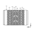
- FIG. 2 is an explanatory view illustrating the molding surface of the studless tire vulcanization mold in plan view.
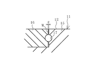
- FIG. 3 is an explanatory view illustrating the molding surface of the cast-in-mold with an enlarged cross-sectional view.
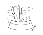
- FIG. 4 is an explanatory view illustrating the laser head and the mold to be cleaned in a side view.
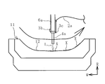
- FIG. 5 is an explanatory view illustrating the laser head and the mold to be cleaned in a front view.
- the tire vulcanization mold is targeted for cleaning, but the present invention is not limited to tires and can be used for cleaning molds for vulcanizing rubber products.
- a mold cleaning system 1 of the present invention illustrated in FIG. 1 includes a laser oscillator 2, a laser head 4, an arm 6 to which the laser head 4 is attached, a control device 7 that controls the movement of the arm 6, and a database 8. And a mark detector 3a.
- a camera 3b that acquires image data of the molding surface 12 of the mold 11 and a temperature sensor 3c that sequentially detects the temperature of the molding surface 12 irradiated with the laser light L are provided. Detection data by the mark detector 3a, image data acquired by the camera 3b, and temperature data detected by the temperature sensor 3c are input to the control device 7.
- the main components of the cleaning system 1 except for the laser oscillator 2 are arranged inside a cleaning booth 9 that is a closed space.
- the cleaning booth 9 is provided with an entrance door 9a and an exit door 9b. When the entrance door 9a and the exit door 9b are closed, the cleaning booth 9 becomes a closed space and can shield the laser beam L.
- a carry-in conveyor device 10a is connected to the entrance door 9a, and a carry-out conveyor device 10c is connected to the exit door 9b.
- the space between the carry-in conveyor device 10a and the carry-out conveyor device 10c is an internal space of the washing booth 9, and the processing conveyor device 10b is disposed at this position.
- the processing conveyor device 10b extends in a circular arc shape.
- the mold 11 to be cleaned is placed on the carry-in conveyor device 10a, and the washed mold 11 is placed on the carry-out conveyor device 10c.
- the processing conveyor device 10b functions as a processing table when the mold 11 is cleaned.
- the laser oscillator 2 and the laser head 4 are connected by an optical fiber cable 2a.
- the laser light L supplied by the laser oscillator 2 is sent to the laser head 4 through the optical fiber cable 2a.
- the laser beam L used in the present invention is preferably a YAG laser beam.
- Laser beam L is applied to the molding surface 12 of the mold 11 by the laser head 4.
- the arm 6 is rotatably attached to the arm base 5 and is configured by connecting a plurality of arm portions 6a and 6b in a freely rotatable manner.
- the laser head 4 is detachably attached to the tip of the arm 6. Therefore, the laser head 4 can be freely moved in three dimensions by controlling the movement of the arm 6.
- a plurality of laser heads 4a and 4b having different laser irradiation widths are provided.
- One is a laser head 4a having a relatively large laser irradiation width
- the other is a laser head 4b having a relatively small laser irradiation width.
- One laser head 4a has a built-in galvanometer mirror and is configured to scan the laser beam L in the width direction and irradiate a wide range.
- the laser irradiation width is variable (for example, 4 mm or more and 70 mm or less).
- the other laser head 4b irradiates the laser beam L at a pinpoint.
- a plurality of laser heads 4a having variable laser irradiation widths may be provided, and the laser irradiation widths may be different from each other.
- the oscillation frequency of the laser oscillator 2 is, for example, 10 kHz or more and 40 kHz or less.
- the frequency at which the laser beam L is scanned in the width direction from the laser head 4a is, for example, 20 Hz to 150 Hz.
- the database 8 is arranged in the storage unit of the control device 7.
- An identification mark D indicating that the mold 11 is the mold 11 is attached to each mold 11 to be cleaned.
- the identification mark D is attached to the mold 11 by attaching a stamp, a label, or the like.
- the identification mark D is composed of numbers, letters, or a combination thereof, for example.
- the database 8 stores shape data of the molding surface 12 of each mold 11. Each shape data is stored in the database 11 together with an identification mark D attached to the mold 11 having the molding surface 12 of the shape data. That is, the database 8 stores the shape data of the molding surface 12 of the mold 11 with the identification mark D and the identification mark D in association with each other.
- the mold 11 to be cleaned is not only a normal type mold but also, for example, a studless tire vulcanization mold shown in FIG.
- a groove forming protrusion 13 and a sipe forming protrusion 14 are projected from a forming surface 12.
- the groove forming protrusion 13 is integrally cast with the base material of the mold 11, and the sipe forming protrusion 14 is attached to the forming surface 12 as a separate body.
- the material of the base material of the mold 11 is mainly aluminum, and the material of the sipe molding protrusion 14 is steel.
- the thickness of the sipe molding protrusion 14 is about 0.4 mm or more and 1.2 mm or less.
- the groove forming protrusion 13 may become thin due to the tread pattern of the tire, for example, in the case of a complicated tread pattern. For this reason, the sipe molding projection 14 and the thin groove molding projection 13 are easily damaged during mold cleaning. 2, 4, and 5 indicate a circumferential direction, a radial direction, and a width direction of a tire that is inserted into the mold 11 and vulcanized.
- molds 11 to be cleaned include, for example, a cast joint mold for pneumatic tire vulcanization shown in FIG.
- the mold 11 is manufactured by a so-called cast joint in which the second casting part 16 is cast after the first casting part 15 is cast.
- a minute gap g is formed in the joint portion M between the first cast portion 15 and the second cast portion 16 by solidification shrinkage of the cast molten metal.
- the size of the minute gap g is, for example, 5 ⁇ m or more and 80 ⁇ m or less.
- An exhaust hole 17 is formed in communication with the minute gap g.
- the mold 11 to be cleaned is placed on the carry-in conveyor device 10a.
- the entrance door 9a is opened, and the carry-in conveyor device 10a and the processing conveyor device 10b are moved to move the mold 11 to be cleaned onto the processing conveyor device 10b and positioned at a predetermined position. Thereafter, the entrance door 9a is closed to make the cleaning booth 9 a closed space. If the cleaning booth 9 does not become a closed space, the laser oscillator 2 does not operate.
- the identification mark D attached to the mold 11 is detected by the mark detector 3a. Based on the detected identification mark D, the shape data of the molding surface 12 of the mold 11 stored in the database 8 is automatically acquired.
- the movement of the arm 6 is controlled based on the acquired shape data of the molding surface 12 of the mold 11, and the laser head 4 is moved along the molding surface 12 as illustrated in FIGS. 4 and 5.
- the laser beam L supplied from the laser oscillator 2 is irradiated onto the molding surface 12 while moving the laser head 4 in this way.
- the dirt X adhering to the molding surface 12 is removed and cleaned by the irradiated laser light L.
- the moving direction of the laser head 4 and the laser are maintained while keeping the distance between the tip of the laser head 4 and the molding surface 12 facing this as constant as possible.
- the irradiation direction of the light L is controlled.
- the moving speed of the laser head 4 is set to a constant speed as much as possible so as to cover the cleaning target range.
- the two laser heads 4a and 4b are used together to irradiate the laser beam L.
- the other laser head 4 can be used after one of the laser heads 4 is used.
- the laser light L using the laser head 4b having a relatively small laser irradiation width is used. Irradiate.
- the shape data of the molding surface 12 of the mold 11 stored in the database 8 based on the identification mark D detected by the mark detector 3a. To get automatically. Therefore, even if a large number of molds 11 having different molding surfaces 12 are to be cleaned, the shape data of the molding surface 12 of the mold 11 to be cleaned is called every time the cleaning is performed. There is no need for manual work to check the correspondence.
- the laser head 4 is irradiated along with the laser beam L while moving along the molding surface 12. Therefore, a studless tire vulcanization mold or a pneumatic tire vulcanization casting is used. Even if the mold 11 has a molding surface 12 having a complicated shape such as a joint mold, it is possible to efficiently remove the dirt X while preventing damage to the molding surface 12 without manpower.
- the image data of the cleaned molding surface 12 is acquired by the camera 3b, and the cleaning state of the molding surface 12 is grasped based on the acquired image data.
- the grasped cleaning state and the position information of the molding surface are stored in the control device 7.
- the laser head 4 After irradiating the entire area of the molding surface 12 with the laser beam L, the laser head 4 is moved again to the position of the molding surface 12 whose grasped cleaning state does not satisfy the preset standard. Then, the laser beam L is irradiated for cleaning.
- the mark detector 3a can be configured to have the function of the camera 3b.
- control device 7 determines whether or not the grasped cleaning state satisfies a preset standard.
- the reference for determining the cleaning state is set based on, for example, the color density of the image data of the molding surface 12 acquired by the camera 3b. If the density is above a certain level, it is set that the stain X remains. Alternatively, it is also possible to acquire image data of the molding surface 12 immediately before and after the irradiation with the laser light L, compare both the image data, and set a reference based on a change in color shading. When the color density is not changed or the degree of change is small, it is set that the stain X remains. With such a setting, only the dirty position (range) is re-washed later, which is advantageous for efficiently removing the dirt X.
- a specific part is inputted and set in advance in the control device 7, and the laser head 4b having a relatively small laser irradiation width is used for the set specific part or a laser is relatively used. Cleaning can be performed using a laser head 4b having a relatively small laser irradiation width in addition to the laser head 4a having a large irradiation width.
- a range of a complicated shape such as a root peripheral range of the sipe forming protrusion 14 illustrated in FIG. 2 or an inner peripheral surface of the minute gap g of the cast joint M illustrated in FIG.
- the temperature of the molding surface 12 irradiated with the laser light L can be sequentially detected by the temperature sensor 3c.
- An allowable temperature is previously input and set in the control device 7. This allowable temperature is set to a predetermined temperature that is less than the melting temperature of the mold 11.
- the temperature detected by the temperature sensor 3c exceeds the preset allowable temperature, the irradiation with the laser light L is interrupted. For example, even if there is a problem that the moving speed of the laser head 4 is slowed or stopped due to an unintended factor, if this setting is made, the molding surface 12 is heated excessively by the irradiated laser light L. It will not be done. That is, it is possible to prevent a problem that the molding surface 12 is thermally deformed or damaged by the laser beam L.
- the exit door 9b is opened and the processing conveyor belt 10b and the carry-out conveyor belt 10c are operated to move the mold 11 that has been cleaned from the inside of the cleaning booth 9 to the outside.
- the entrance door 9a is opened, the carry-in conveyor belt 10a is operated, and the mold 11 to be cleaned next is moved from the outside to the inside of the cleaning booth 9, and positioned at a predetermined position on the processing conveyor 10b. In this manner, the mold 11 is sequentially and continuously cleaned.
Landscapes
- Engineering & Computer Science (AREA)
- Mechanical Engineering (AREA)
- Physics & Mathematics (AREA)
- Optics & Photonics (AREA)
- Plasma & Fusion (AREA)
- Moulds For Moulding Plastics Or The Like (AREA)
Abstract
複雑な形状の成形面を有するモールドであっても、人手をかけずに、成形面の損傷を防止しつつ汚れを効率よく除去できるモールドの洗浄システムを提供する。モールド11を洗浄する際にマーク検知器3aにより検知されたこのモールド11に付された識別マークDに基づいて、データベース8に記憶されているこのモールド11の成形面12の形状データを取得し、取得した形状データに基づいてアーム6a、6bの動きを制御装置7によって制御して、レーザヘッド4をその成形面12に沿って移動させつつ、レーザ発振器2から供給されるレーザ光Lを照射してその成形面12に付着した汚れXを除去する。
Description
本発明は、モールドの洗浄システムに関し、さらに詳しくは、複雑な形状の成形面を有するモールドであっても、人手をかけずに、成形面の損傷を防止しつつ汚れを効率よく除去できるモールドの洗浄システムに関するものである。
タイヤ等のゴム製品を加硫するためのモールドの成形面には、加硫する度に、僅かながらゴム成分や配合剤に由来する汚れが付着する。モールドの繰り返し使用によって、この汚れが徐々に累積するので、そのまま汚れを放置すれば、加硫する製品の品質に悪影響が生じる。そのため適宜、成形面を洗浄して汚れを除去する必要がある。モールドを洗浄する方法としては、ショットブラスト洗浄方法、レーザ光洗浄方法、プラズマ洗浄方法等が知られている。
ショットブラスト洗浄方法では、成形面が損傷し易いので、洗浄による成形面の損傷を防止するには、レーザ光を成形面に照射してその衝撃波によって汚れを除去するレーザ光洗浄方法や、発生させたプラズマによって汚れを化学反応させて除去するプラズマ洗浄方法が望ましい。ただし、プラズマ洗浄方法は、単位時間に洗浄できる面積が小さいので、効率性を考慮するとレーザ光洗浄方法がより望ましい。
レーザ光を用いたモールドの洗浄方法は種々提案されている(例えば、特許文献1、2参照)。特許文献1に記載の洗浄方法では、レーザ発振器から供給されるレーザ光(CO2レーザ光)をレーザヘッドからモールドの成形面に照射して汚れを除去する。この際に、レーザヘッドを移動させるアーム(マニピュレータ)は、モールドの原形状データ(キャドデータなど)とレーザヘッドの位置補正手段によって制御され、レーザヘッドを成形面の凹凸に沿って移動させる(特許文献1の段落0011、0021~0025等参照)。
しなしながら、モールドの成形面は同じ形状に形成されているとは限らず、様々な形状に形成されている。そのため、特許文献1に記載の方法では、成形面が異なる形状のモールドを洗浄するには、モールドの洗浄を行なうに度に制御装置に記憶されているこのモールドの原形状データを呼び出す作業が必要になる。成形面の形状が膨大な種類になるタイヤ加硫用モールドの場合は、洗浄の都度、洗浄するモールドと原形状データとが対応していることを確認する必要があり、作業が煩雑になるという問題がある。
特許文献2に記載の洗浄方法では、レーザ照射器を所定位置に固定して、モールドを移動させてモールド表面がレーザ光の光軸に対して垂直な姿勢から傾斜した姿勢になるようにモールドを回動させる。モールドをこのように回動させるには、この動きを事前にティーチングする等の工程が必要なる。
本発明の目的は、複雑な形状の成形面を有するモールドであっても、人手をかけずに、成形面の損傷を防止しつつ汚れを効率よく除去できるモールドの洗浄システムを提供することにある。
上記目的を達成するため本発明のモールドの洗浄システムは、レーザ発振器と、このレーザ発振器からのレーザ光をモールドの成形面に照射するレーザヘッドと、このレーザヘッドを3次元に自在移動させるアームと、このアームの動きを制御する制御装置とを備えたモールドの洗浄システムにおいて、洗浄するモールド毎に付されたそのモールドを示す識別マークと、この識別マークが付されたモールドの成形面の形状データとが関連付けて予め記憶されているデータベースと、前記識別マークを検知するマーク検知器とを備え、モールドを洗浄する際に前記マーク検知器により検知されたこのモールドに付された識別マークに基づいて、前記データベースに記憶されているこのモールドの成形面の形状データを取得し、この取得した形状データに基づいて前記アームの動きを制御することにより、前記レーザヘッドをその成形面に沿って移動させつつ、レーザ光を照射してその成形面を洗浄することを特徴とする。
本発明によれば、モールドを洗浄する際に、洗浄するモールドに付された識別マークをマーク検知器により検知し、検知した識別マークに基づいて、データベースに記憶されているこのモールドの成形面の形状データを自動的に取得するので、洗浄する度に洗浄対象となるモールドの成形面の形状データを呼び出し、さらに、モールド実物と形状データとの対応関係を確認する人手を介した作業が不要になる。そして、データベースから取得した形状データに基づいて、レーザヘッドをその成形面に沿って移動させつつ、レーザ光を照射してその成形面を洗浄するので、複雑な形状の成形面を有するモールドであっても、人手をかけることなく、成形面の損傷を防止しつつ汚れを効率よく除去することが可能になる。
ここで、例えば、前記成形面の画像データを取得するカメラを備え、このカメラにより取得された前記画像データに基づいてその成形面の洗浄状態を把握し、この把握した洗浄状態およびその成形面の位置情報を前記制御装置に記憶し、前記把握した洗浄状態が予め設定されている基準に満たない成形面の位置に対して、再度、前記レーザヘッドから前記レーザ光を照射して洗浄を行なう設定にすることもできる。この設定にすると、特に汚れている位置(範囲)だけを後から再洗浄するので、汚れを効率よく綺麗に除去するには有利になる。
前記レーザヘッドとして、レーザ照射幅が異なる複数のレーザヘッドを備え、予め設定されている特定の部位に対しては、相対的にレーザ照射幅が小さいレーザヘッドを用いて、または、相対的にレーザ照射幅が大きいレーザヘッドに加えて相対的にレーザ照射幅が小さいレーザヘッドを用いて洗浄を行なう設定することもできる。この設定にすると、比較的平坦で広い部位に対しては相対的にレーザ照射幅が大きいレーザヘッドを用いることで洗浄を短時間で完了することができる。一方、成形面の狭い範囲に凹凸が複雑に入り込んだ部位に対しては、相対的にレーザ照射幅が小さいレーザヘッドを用いることで、複雑な形状の部分にもムラなくレーザ光を照射できるので、汚れを綺麗に除去することができる。
前記レーザ光が照射されている前記成形面の温度を逐次検知する温度センサを備え、この温度センサによる検知温度が予め設定されている許容温度を超えた場合には、前記レーザ光の照射を中断する設定にすることもできる。この設定の場合には、照射するレーザ光によって成形面が過度に加熱されることが回避できる。即ち、成形面がレーザ光によって熱変形する不具合を防止できる。
スタッドレスタイヤ加硫用モールドは成形面が複雑な形状であり、空気入りタイヤ加硫用鋳継ぎモールドは成形面に微小なすき間が形成されているが、本発明を適用することにより、成形面の損傷を防止しつつ汚れを効率よく除去できる。
本発明のモールドの洗浄システムを図に示した実施形態に基づいて説明する。
以下の説明では、タイヤ加硫用モールドを洗浄対象としているが、本発明はタイヤに限らずゴム製品を加硫するためのモールドの洗浄に用いることができる。
図1に例示する本発明のモールドの洗浄システム1は、レーザ発振器2と、レーザヘッド4と、レーザヘッド4が取り付けられるアーム6と、アーム6の動きを制御する制御装置7と、データベース8と、マーク検知器3aとを備えている。この実施形態では、更にモールド11の成形面12の画像データを取得するカメラ3bと、レーザ光Lが照射されている成形面12の温度を逐次検知する温度センサ3cとを備えている。マーク検知器3aによる検知データ、カメラ3bが取得した画像データ、温度センサ3cが検知した温度データは制御装置7に入力される。
レーザ発振器2を除いて洗浄システム1の主な構成要素は、閉空間となる洗浄ブース9の内部に配置されている。洗浄ブース9には入口扉9aと出口扉9bとが設けられていて、入口扉9aおよび出口扉9bが閉じられると閉空間になり、レーザ光Lを遮蔽できる構造になっている。
入口扉9aには搬入用コンベヤ装置10aが接続され、出口扉9bには搬出用コンベヤ装置10cが接続されている。搬入用コンベヤ装置10aと搬出用コンベヤ装置10cとの間は洗浄ブース9の内部空間になり、この位置には処理用コンベヤ装置10bが配置されている。この実施形態では処理用コンベヤ装置10bは円弧状に曲がって延設されている。搬入用コンベヤ装置10aには洗浄されるモールド11が載置され、搬出用コンベヤ装置10cには洗浄されたモールド11が載置される。処理用コンベヤ装置10bはモールド11を洗浄する際の処理台として機能する。
レーザ発振器2とレーザヘッド4とは光ファイバーケーブル2aによって接続されている。レーザ発振器2により供給されたレーザ光Lは光ファイバーケーブル2aを通じてレーザヘッド4に送られる。本発明で使用するレーザ光LとしてはYAGレーザ光が好ましい。
レーザヘッド4により、レーザ光Lがモールド11の成形面12に照射される。アーム6はアームベース5に回転自在に取り付けられていて、複数のアーム部6a、6bを回転自在に接続して構成されている。アーム6の先端部にレーザヘッド4が着脱自在に装着される。したがって、アーム6の動きを制御することにより、レーザヘッド4を3次元に自在移動させることができる。
この実施形態では、図4に例示するようにレーザ照射幅が異なる複数のレーザヘッド4a、4bを備えている。一方は相対的にレーザ照射幅が大きいレーザヘッド4aであり、他方は相対的にレーザ照射幅が小さいレーザヘッド4bである。一方のレーザヘッド4aは、ガルバノミラーを内蔵していてレーザ光Lを幅方向にスキャンして幅広に照射できる構成になっている。レーザ照射幅は可変(例えば4mm以上70mm以下)になっている。他方のレーザヘッド4bは、ピンポイントにレーザ光Lを照射する。レーザ照射幅が可変のレーザヘッド4aを複数備えて、互いのレーザ照射幅を異ならせてもよい。レーザ発振器2の発振周波数は例えば、10kHz以上40kHz以下である。レーザヘッド4aからレーザ光Lを幅方向にスキャンする周波数は例えば20Hz以上150Hz以下である。
データベース8は、制御装置7の記憶部に配置されている。洗浄するモールド11にはモールド11毎にそのモールド11であることを示す識別マークDが付されている。識別マークDは、刻印やラベル等を貼付することによりモールド11に付される。識別マークDは例えば、数字や文字またはこれらの組み合わせで構成される。
データベース8には、それぞれのモールド11の成形面12の形状データが記憶されている。また、それぞれの形状データはその形状データの成形面12を有するモールド11に付された識別マークDとともにデータベース11に記憶されている。即ち、データベース8には、識別マークDが付されたモールド11の成形面12の形状データと識別マークDとが関連付けられて予め記憶されている。
洗浄対象となるモールド11は通常タイプのモールドだけでなく、例えば図2に示すスタッドレスタイヤ加硫用モールドである。このモールド11は、成形面12に溝成形突起13、サイプ成形突起14が突設されている。溝成形突起13はモールド11の母材と一体的に鋳造されたものであり、サイプ成形突起14は別体として成形面12に取付けられたものである。モールド11の母材の材質は主にアルミニウム、サイプ成形突起14の材質は鋼等である。
サイプ成形突起14の厚さは、0.4mm以上1.2mm以下程度である。溝成形突起13は、タイヤのトレッドバターンによって、例えば、複雑なトレッドパターンの場合には薄くなることがある。そのため、サイプ成形突起14や薄肉の溝成形突起13は、モールド洗浄の際には損傷し易い部分となる。尚、図2、図4、図5に記載されているC矢印、R矢印、W矢印は、それぞれ、モールド11に挿入して加硫するタイヤの周方向、半径方向、幅方向を示す。
その他、洗浄対象となる別の種類のモールド11としては、例えば図3に示す空気入りタイヤ加硫用鋳継ぎモールドである。このモールド11は、第1鋳造部15を鋳造した後に第2鋳造部16を鋳造するいわゆる鋳継ぎによって製造されたものである。鋳込まれた溶融金属の凝固収縮によって第1鋳造部15と第2鋳造部16との鋳継ぎ部Mには微小すき間gが形成されている。この微小すき間gの大きさは例えば5μm以上80μm以下である。微小すき間gに連通させて排気穴17が形成されている。このモールド11では、タイヤ加硫時の不要なエアやガスは、成形面12から微小すき間gを通じて排気穴17に排出され、排気穴17を通じてモールド11の外部に排出される。この微小すき間gはモールド洗浄の際には損傷し易い部分となる。
次に、この洗浄システム1を用いてモールド11の成形面12を洗浄する手順を説明する。
まず、洗浄するモールド11を搬入用コンベヤ装置10aに載置する。次いで、入口扉9aを開き、搬入用コンベヤ装置10aおよび処理用コンベヤ装置10bを稼働して洗浄するモールド11を処理用コンベヤ装置10bの上に移動させて所定位置に位置決めする。その後、入口扉9aを閉めて洗浄ブース9を閉空間にする。洗浄ブース9が閉空間にならなければレーザ発振器2が作動しないインターロック構造になっている。
次いで、マーク検知器3aによってモールド11に付されている識別マークDを検知する。この検知した識別マークDに基づいて、データベース8に記憶されているこのモールド11の成形面12の形状データを自動的に取得する。
次いで、取得したそのモールド11の成形面12の形状データに基づいてアーム6の動きを制御して、図4、図5に例示するようにレーザヘッド4をその成形面12に沿って移動させる。このようにレーザヘッド4を移動させつつ、レーザ発振器2から供給されたレーザ光Lを成形面12に照射する。照射したレーザ光Lによって成形面12に付着していた汚れXは除去されて洗浄される。
ここで、レーザ光Lの照射ムラを抑えるために、レーザヘッド4の先端と、これに対向する成形面12との間隔がなるべく一定になるように維持しつつ、レーザヘッド4の移動方向およびレーザ光Lの照射方向を制御する。レーザヘッド4の移動速度はなるべく一定の速度にして洗浄対象範囲を網羅するように移動させる。
この実施形態では、2つのレーザヘッド4a、4bを一緒に使用してレーザ光Lを照射しているが、いずれか一方のレーザヘッド4を使用した後に他方のレーザヘッド4を使用することもできる。例えば、相対的にレーザ照射幅が大きいレーザヘッド4aを洗浄対象範囲を網羅するように移動させてレーザ光Lを照射した後に、相対的にレーザ照射幅が小さいレーザヘッド4bを用いてレーザ光Lを照射する。
上述したように、本発明によれば、モールド11を洗浄する際に、マーク検知器3aにより検知した識別マークDに基づいて、データベース8に記憶されているこのモールド11の成形面12の形状データを自動的に取得する。それ故、成形面12の異なる多数のモールド11が洗浄対象であったとしても、洗浄する度に洗浄対象となるモールド11の成形面12の形状データを呼び出し、さらに、モールド実物と形状データとの対応関係を確認する人手を介した作業が不要になる。
そして、データベース8から取得した形状データに基づいて、レーザヘッド4をその成形面12に沿って移動させつつ、レーザ光Lを照射するので、スタッドレスタイヤ加硫用モールドや空気入りタイヤ加硫用鋳継ぎモールドのような複雑な形状の成形面12を有するモールド11であっても、人手をかけることなく、成形面12の損傷を防止しつつ汚れXを効率よく除去することが可能になる。
この実施形態では、洗浄した成形面12の画像データをカメラ3bによって取得し、この取得した画像データに基づいてその成形面12の洗浄状態を把握する。把握した洗浄状態およびその成形面の位置情報は制御装置7に記憶しておく。成形面12のすべての範囲にレーザ光Lを照射した後に、把握した洗浄状態が予め設定されている基準に満たない成形面12の位置に対しては、再度、レーザヘッド4をその位置に移動させてレーザ光Lを照射して洗浄を行なう。マーク検知器3aにこのカメラ3bの機能を持たせて兼用させた構成にすることもできる。
制御装置7には洗浄状態が適切(汚れXが除去されている)か不適切(汚れXが残っている)かを判断する基準が予め入力、設定されている。そこで、制御装置7により、把握した洗浄状態が予め設定されている基準を満たしているか否かを判断する。
洗浄状態を判断する基準は、例えば、カメラ3bにより取得した成形面12の画像データの色の濃淡に基づいて設定される。ある一定以上の濃度の場合は汚れXが残っていると設定する。或いは、レーザ光Lが照射される直前と照射された直後の成形面12の画像データを取得し、両画像データを比較して色の濃淡の変化に基づいて基準を設定することもできる。色の濃淡が変化していない、または変化の度合いが小さい場合は、汚れXが残っていると設定する。このような設定にすると、特に汚れている位置(範囲)だけを後から再洗浄するので、汚れXを効率よく綺麗に除去するには有利になる。
予め特定の部位を制御装置7に入力、設定しておき、この設定されている特定の部位に対しては、相対的にレーザ照射幅が小さいレーザヘッド4bを用いて、または、相対的にレーザ照射幅が大きいレーザヘッド4aに加えて相対的にレーザ照射幅が小さいレーザヘッド4bを用いて洗浄を行なうこともできる。特定の部位としては、例えば、図2に例示したサイプ成形突起14の根元周辺範囲などの複雑な形状の範囲や図3に例示した鋳継ぎ部Mの微小すき間gの内周面とする。
この設定にすると、比較的平坦で広い部位に対しては相対的にレーザ照射幅が大きいレーザヘッド4aを用いることで洗浄を短時間で終えることができる。一方、成形面12の狭い範囲に凹凸が複雑に入り込んだ部位に対しては、相対的にレーザ照射幅が小さいレーザヘッド4bを用いることで、複雑な形状の部分にもムラなくレーザ光Lを照射できるので、汚れXを綺麗に除去することができる。
レーザ光Lが照射されている成形面12の温度を温度センサ3cによって逐次検知することもできる。制御装置7には許容温度を予め入力、設定しておく。この許容温度は、モールド11の溶融温度に満たない所定温度にする。温度センサ3cによる検知温度が予め設定されている許容温度を超えた場合には、レーザ光Lの照射を中断する。例えば、意図しない要因によってレーザヘッド4の移動速度が遅くなる、停止する等の不具合があった場合であっても、この設定にしておくと、照射するレーザ光Lによって成形面12が過度に加熱されることがなくなる。即ち、成形面12がレーザ光Lによって熱変形や損傷する不具合を防止できる。
モールド11の洗浄が完了した後は、出口扉9bを開き、処理用コンベヤベルト10bおよび搬出用コンベヤベルト10cを稼働させて洗浄が完了したモールド11を洗浄ブース9の内部から外部に移動させる。この際に、入口扉9aを開き、搬入用コンベヤベルト10aを稼働させて次に洗浄するモールド11を洗浄ブース9の外部から内部に移動させて、処理用コンベヤ10b上の所定位置に位置決めする。このようにして、順次連続的にモールド11を洗浄する。
1 洗浄システム
2 レーザ発振器
2a 光ファイバーケーブル
3a マーク検知器
3b カメラ
3c 温度センサ
4、4a、4b レーザヘッド
5 アームベース
6 アーム
6a、6b アーム部
7 制御装置
8 データベース
9 洗浄ブース
9a 入口扉
9b 出口扉
10a 搬入用コンベヤ装置
10b 処理用コンベヤ装置(処理台)
10c 搬出用コンベヤ装置
11 モールド
12 成形面
13 溝成形突起
14 サイプ成形突起
15 第1鋳造部
16 第2鋳造部
17 排気穴
D 識別マーク
M 鋳継ぎ部
L レーザ光
X 汚れ
g 微小すき間
2 レーザ発振器
2a 光ファイバーケーブル
3a マーク検知器
3b カメラ
3c 温度センサ
4、4a、4b レーザヘッド
5 アームベース
6 アーム
6a、6b アーム部
7 制御装置
8 データベース
9 洗浄ブース
9a 入口扉
9b 出口扉
10a 搬入用コンベヤ装置
10b 処理用コンベヤ装置(処理台)
10c 搬出用コンベヤ装置
11 モールド
12 成形面
13 溝成形突起
14 サイプ成形突起
15 第1鋳造部
16 第2鋳造部
17 排気穴
D 識別マーク
M 鋳継ぎ部
L レーザ光
X 汚れ
g 微小すき間
Claims (5)
- レーザ発振器と、このレーザ発振器から供給されるレーザ光をモールドの成形面に照射するレーザヘッドと、このレーザヘッドを3次元に自在移動させるアームと、このアームの動きを制御する制御装置とを備えたモールドの洗浄システムにおいて、
洗浄するモールド毎に付されたそのモールドを示す識別マークと、この識別マークが付されたモールドの成形面の形状データとが関連付けられて予め記憶されているデータベースと、前記識別マークを検知するマーク検知器とを備え、モールドを洗浄する際に前記マーク検知器により検知されたこのモールドに付された識別マークに基づいて、前記データベースに記憶されているこのモールドの成形面の形状データを取得し、この取得した形状データに基づいて前記アームの動きを制御することにより、前記レーザヘッドをその成形面に沿って移動させつつ、レーザ光を照射してその成形面を洗浄することを特徴とするモールドの洗浄システム。 - 前記成形面の画像データを取得するカメラを備え、このカメラにより取得された前記画像データに基づいてその成形面の洗浄状態を把握し、この把握した洗浄状態およびその成形面の位置情報を前記制御装置に記憶し、前記把握した洗浄状態が予め設定されている基準に満たない成形面の位置に対して、再度、前記レーザヘッドから前記レーザ光を照射して洗浄を行なう設定にした請求項1に記載のモールドの洗浄システム。
- 前記レーザヘッドとして、レーザ照射幅が異なる複数のレーザヘッドを備え、予め設定されている特定の部位に対しては、相対的にレーザ照射幅が小さいレーザヘッドを用いて、または、相対的にレーザ照射幅が大きいレーザヘッドに加えて相対的にレーザ照射幅が小さいレーザヘッドを用いて洗浄を行なう設定にした請求項1または2に記載のモールドの洗浄システム。
- 前記レーザ光が照射されている前記成形面の温度を逐次検知する温度センサを備え、この温度センサによる検知温度が予め設定されている許容温度を超えた場合には、前記レーザ光の照射を中断する設定にした請求項1~3のいずれかに記載のモールドの洗浄システム。
- 前記モールドがスタッドレスタイヤ加硫用モールドまたは空気入りタイヤ加硫用鋳継ぎモールドである請求項1~4のいずれかに記載のモールドの洗浄システム。
Priority Applications (3)
| Application Number | Priority Date | Filing Date | Title |
|---|---|---|---|
| US15/309,410 US11072139B2 (en) | 2014-05-09 | 2015-05-08 | Mold cleaning system |
| CN201580023332.4A CN106457620A (zh) | 2014-05-09 | 2015-05-08 | 模具的清洗系统 |
| EP15789593.9A EP3141367B1 (en) | 2014-05-09 | 2015-05-08 | Mold cleaning system |
Applications Claiming Priority (2)
| Application Number | Priority Date | Filing Date | Title |
|---|---|---|---|
| JP2014-097993 | 2014-05-09 | ||
| JP2014097993A JP5835400B2 (ja) | 2014-05-09 | 2014-05-09 | モールドの洗浄システム |
Publications (1)
| Publication Number | Publication Date |
|---|---|
| WO2015170750A1 true WO2015170750A1 (ja) | 2015-11-12 |
Family
ID=54392598
Family Applications (1)
| Application Number | Title | Priority Date | Filing Date |
|---|---|---|---|
| PCT/JP2015/063335 WO2015170750A1 (ja) | 2014-05-09 | 2015-05-08 | モールドの洗浄システム |
Country Status (5)
| Country | Link |
|---|---|
| US (1) | US11072139B2 (ja) |
| EP (1) | EP3141367B1 (ja) |
| JP (1) | JP5835400B2 (ja) |
| CN (2) | CN106457620A (ja) |
| WO (1) | WO2015170750A1 (ja) |
Cited By (1)
| Publication number | Priority date | Publication date | Assignee | Title |
|---|---|---|---|---|
| JP2017128013A (ja) * | 2016-01-19 | 2017-07-27 | 住友ゴム工業株式会社 | ベントホール洗浄装置及びベントホール洗浄方法。 |
Families Citing this family (16)
| Publication number | Priority date | Publication date | Assignee | Title |
|---|---|---|---|---|
| KR20130105838A (ko) | 2010-08-24 | 2013-09-26 | 바스프 에스이 | 전기화학 셀용 전해질 물질 |
| US9577289B2 (en) | 2012-12-17 | 2017-02-21 | Sion Power Corporation | Lithium-ion electrochemical cell, components thereof, and methods of making and using same |
| JP5892198B2 (ja) * | 2014-06-26 | 2016-03-23 | 横浜ゴム株式会社 | モールドの洗浄システム |
| KR101735373B1 (ko) | 2016-03-11 | 2017-05-16 | 주식회사 제펠 | 상부금형의 스크랩을 제거하기 위한 레이저 세정장치 |
| DE102017206815A1 (de) * | 2017-04-24 | 2018-10-25 | Volkswagen Aktiengesellschaft | Verfahren zur Säuberung eines generativ gefertigten Teils |
| CN107309221B (zh) * | 2017-08-09 | 2019-12-24 | 温州大学激光与光电智能制造研究院 | 一种双波长复合光束整形的手持式自适应激光清洗装置 |
| US10744539B2 (en) * | 2017-10-27 | 2020-08-18 | The Boeing Company | Optimized-coverage selective laser ablation systems and methods |
| EP3732009B1 (en) | 2017-12-28 | 2022-07-27 | Greentech Laser Manufactoring S.p.A. | Automatic plant for cleaning moulds for tyres |
| JP6590010B2 (ja) * | 2018-02-09 | 2019-10-16 | 横浜ゴム株式会社 | 加硫用モールドの洗浄装置および方法 |
| AU2018203176A1 (en) * | 2018-05-08 | 2019-11-28 | Automation Innovation Pty Ltd | Laser cleaning system |
| JP7238555B2 (ja) * | 2019-04-03 | 2023-03-14 | 住友ゴム工業株式会社 | 金型面のレーザ洗浄方法 |
| JP7117264B2 (ja) * | 2019-04-16 | 2022-08-12 | 株式会社ブリヂストン | ベントホール清掃装置及びベントホール清掃方法 |
| CN111420938B (zh) * | 2020-04-28 | 2022-03-15 | 株洲国创轨道科技有限公司 | 一种多激光头智能化激光清洗方法及装置 |
| US11748942B2 (en) | 2020-08-13 | 2023-09-05 | Siemens Mobility Pty Ltd | System and method for automatically generating trajectories for laser applications |
| CN113351580B (zh) * | 2021-07-06 | 2024-03-29 | 联亚智能科技(苏州)有限公司 | 通过识别标记检测轮胎内表面激光清洗质量的方法 |
| CN117141021B (zh) * | 2023-10-31 | 2024-01-26 | 山东产研强远激光科技有限公司 | 一种轮胎模具花纹块与侧板用激光清洗装置及方法 |
Citations (4)
| Publication number | Priority date | Publication date | Assignee | Title |
|---|---|---|---|---|
| US6369353B1 (en) * | 1998-02-20 | 2002-04-09 | The Goodyear Tire & Rubber Company | Robotic laser tire mold cleaning system and method of use |
| JP2003112136A (ja) * | 2001-10-05 | 2003-04-15 | Canon Inc | リサイクル部品の洗浄システム及びその方法 |
| JP2004018239A (ja) * | 2002-06-20 | 2004-01-22 | Towa Corp | 保管方法及び保管装置 |
| JP2008062633A (ja) * | 2006-08-09 | 2008-03-21 | Tosei Electro Beam Kk | レーザ加工を用いた金型などの洗浄方法及び洗浄装置並びにタイヤ成形金型の洗浄装置 |
Family Cites Families (10)
| Publication number | Priority date | Publication date | Assignee | Title |
|---|---|---|---|---|
| JPH1128900A (ja) * | 1997-05-12 | 1999-02-02 | Sumitomo Heavy Ind Ltd | レーザ光を用いた塗装除去方法及びレーザ処理装置 |
| JP2002503551A (ja) | 1998-02-20 | 2002-02-05 | ザ・グッドイヤー・タイヤ・アンド・ラバー・カンパニー | ロボット式レーザタイヤ金型清浄システムおよび使用方法 |
| JP3566580B2 (ja) | 1999-05-26 | 2004-09-15 | Necセミコンダクターズ九州株式会社 | 樹脂封止金型のクリーニング装置、樹脂封止金型クリーニング方法およびクリーニングシステム |
| US20010056313A1 (en) | 2000-05-08 | 2001-12-27 | Osborne William Joseph | Object locating and retrieving system utilizing labels |
| JP2003220371A (ja) * | 2002-01-30 | 2003-08-05 | Toyo Tire & Rubber Co Ltd | 金型洗浄方法及び洗浄装置 |
| JP2004167744A (ja) | 2002-11-18 | 2004-06-17 | Toyo Tire & Rubber Co Ltd | 金型洗浄方法及び洗浄装置 |
| CN100540324C (zh) * | 2006-03-10 | 2009-09-16 | 株式会社尼利可 | 标记装置及标记方法 |
| JP5515425B2 (ja) * | 2009-05-27 | 2014-06-11 | 横浜ゴム株式会社 | タイヤ加硫用モールドの洗浄方法 |
| KR101877432B1 (ko) * | 2012-02-06 | 2018-07-11 | 삼성전자주식회사 | 프로브 카드의 니들들을 자동으로 포커싱하고 클리닝하는 방법 |
| DE102012107225A1 (de) | 2012-08-07 | 2014-02-13 | enotech AG | Vorrichtung und Verfahren zum Reinigen von Vulkanisationsformen |
-
2014
- 2014-05-09 JP JP2014097993A patent/JP5835400B2/ja active Active
-
2015
- 2015-05-08 CN CN201580023332.4A patent/CN106457620A/zh active Pending
- 2015-05-08 WO PCT/JP2015/063335 patent/WO2015170750A1/ja active Application Filing
- 2015-05-08 EP EP15789593.9A patent/EP3141367B1/en active Active
- 2015-05-08 US US15/309,410 patent/US11072139B2/en active Active
- 2015-05-08 CN CN202111384766.0A patent/CN114102928A/zh active Pending
Patent Citations (4)
| Publication number | Priority date | Publication date | Assignee | Title |
|---|---|---|---|---|
| US6369353B1 (en) * | 1998-02-20 | 2002-04-09 | The Goodyear Tire & Rubber Company | Robotic laser tire mold cleaning system and method of use |
| JP2003112136A (ja) * | 2001-10-05 | 2003-04-15 | Canon Inc | リサイクル部品の洗浄システム及びその方法 |
| JP2004018239A (ja) * | 2002-06-20 | 2004-01-22 | Towa Corp | 保管方法及び保管装置 |
| JP2008062633A (ja) * | 2006-08-09 | 2008-03-21 | Tosei Electro Beam Kk | レーザ加工を用いた金型などの洗浄方法及び洗浄装置並びにタイヤ成形金型の洗浄装置 |
Cited By (3)
| Publication number | Priority date | Publication date | Assignee | Title |
|---|---|---|---|---|
| JP2017128013A (ja) * | 2016-01-19 | 2017-07-27 | 住友ゴム工業株式会社 | ベントホール洗浄装置及びベントホール洗浄方法。 |
| WO2017126251A1 (ja) * | 2016-01-19 | 2017-07-27 | 住友ゴム工業株式会社 | ベントホール洗浄装置及びベントホール洗浄方法 |
| US10933450B2 (en) | 2016-01-19 | 2021-03-02 | Sumitomo Rubber Industries, Ltd. | Vent hole cleaning apparatus and vent hole cleaning method |
Also Published As
| Publication number | Publication date |
|---|---|
| CN114102928A (zh) | 2022-03-01 |
| US11072139B2 (en) | 2021-07-27 |
| EP3141367A1 (en) | 2017-03-15 |
| EP3141367B1 (en) | 2020-01-08 |
| EP3141367A4 (en) | 2018-01-10 |
| CN106457620A (zh) | 2017-02-22 |
| JP2015214076A (ja) | 2015-12-03 |
| JP5835400B2 (ja) | 2015-12-24 |
| US20170182722A1 (en) | 2017-06-29 |
Similar Documents
| Publication | Publication Date | Title |
|---|---|---|
| JP5835400B2 (ja) | モールドの洗浄システム | |
| JP5892198B2 (ja) | モールドの洗浄システム | |
| JP6260720B2 (ja) | モールドの洗浄システム | |
| US10343194B2 (en) | Tire cleaning system | |
| JP7350751B2 (ja) | タイヤの金型洗浄用自動プラント | |
| JP2016150544A (ja) | ベントホール清掃治具、ベントホール清掃装置およびベントホール清掃方法 | |
| JP2021112889A (ja) | 加硫用モールドの洗浄方法および装置 | |
| US11897218B2 (en) | Cleaning device and method for cleaning vulcanization mold | |
| JP7014215B2 (ja) | タイヤの洗浄方法およびタイヤの製造方法 | |
| WO2020250964A1 (ja) | タイヤの洗浄方法およびタイヤの製造方法 | |
| JP2021011026A (ja) | 加硫用モールドの洗浄方法および装置並びにタイヤの製造方法 |
Legal Events
| Date | Code | Title | Description |
|---|---|---|---|
| 121 | Ep: the epo has been informed by wipo that ep was designated in this application |
Ref document number: 15789593 Country of ref document: EP Kind code of ref document: A1 |
|
| WWE | Wipo information: entry into national phase |
Ref document number: 15309410 Country of ref document: US |
|
| NENP | Non-entry into the national phase |
Ref country code: DE |
|
| REEP | Request for entry into the european phase |
Ref document number: 2015789593 Country of ref document: EP |
|
| WWE | Wipo information: entry into national phase |
Ref document number: 2015789593 Country of ref document: EP |