WO2015170485A1 - 流体式動力伝達装置 - Google Patents
流体式動力伝達装置 Download PDFInfo
- Publication number
- WO2015170485A1 WO2015170485A1 PCT/JP2015/051935 JP2015051935W WO2015170485A1 WO 2015170485 A1 WO2015170485 A1 WO 2015170485A1 JP 2015051935 W JP2015051935 W JP 2015051935W WO 2015170485 A1 WO2015170485 A1 WO 2015170485A1
- Authority
- WO
- WIPO (PCT)
- Prior art keywords
- base plate
- dynamic damper
- transmission device
- fluid
- power transmission
- Prior art date
- Legal status (The legal status is an assumption and is not a legal conclusion. Google has not performed a legal analysis and makes no representation as to the accuracy of the status listed.)
- Ceased
Links
Images






Classifications
-
- F—MECHANICAL ENGINEERING; LIGHTING; HEATING; WEAPONS; BLASTING
- F16—ENGINEERING ELEMENTS AND UNITS; GENERAL MEASURES FOR PRODUCING AND MAINTAINING EFFECTIVE FUNCTIONING OF MACHINES OR INSTALLATIONS; THERMAL INSULATION IN GENERAL
- F16H—GEARING
- F16H45/00—Combinations of fluid gearings for conveying rotary motion with couplings or clutches
- F16H45/02—Combinations of fluid gearings for conveying rotary motion with couplings or clutches with mechanical clutches for bridging a fluid gearing of the hydrokinetic type
-
- F—MECHANICAL ENGINEERING; LIGHTING; HEATING; WEAPONS; BLASTING
- F16—ENGINEERING ELEMENTS AND UNITS; GENERAL MEASURES FOR PRODUCING AND MAINTAINING EFFECTIVE FUNCTIONING OF MACHINES OR INSTALLATIONS; THERMAL INSULATION IN GENERAL
- F16F—SPRINGS; SHOCK-ABSORBERS; MEANS FOR DAMPING VIBRATION
- F16F15/00—Suppression of vibrations in systems; Means or arrangements for avoiding or reducing out-of-balance forces, e.g. due to motion
- F16F15/10—Suppression of vibrations in rotating systems by making use of members moving with the system
- F16F15/12—Suppression of vibrations in rotating systems by making use of members moving with the system using elastic members or friction-damping members, e.g. between a rotating shaft and a gyratory mass mounted thereon
- F16F15/121—Suppression of vibrations in rotating systems by making use of members moving with the system using elastic members or friction-damping members, e.g. between a rotating shaft and a gyratory mass mounted thereon using springs as elastic members, e.g. metallic springs
- F16F15/123—Wound springs
- F16F15/12353—Combinations of dampers, e.g. with multiple plates, multiple spring sets, i.e. complex configurations
- F16F15/1236—Combinations of dampers, e.g. with multiple plates, multiple spring sets, i.e. complex configurations resulting in a staged spring characteristic, e.g. with multiple intermediate plates
- F16F15/12366—Combinations of dampers, e.g. with multiple plates, multiple spring sets, i.e. complex configurations resulting in a staged spring characteristic, e.g. with multiple intermediate plates acting on multiple sets of springs
- F16F15/12373—Combinations of dampers, e.g. with multiple plates, multiple spring sets, i.e. complex configurations resulting in a staged spring characteristic, e.g. with multiple intermediate plates acting on multiple sets of springs the sets of springs being arranged at substantially the same radius
-
- F—MECHANICAL ENGINEERING; LIGHTING; HEATING; WEAPONS; BLASTING
- F16—ENGINEERING ELEMENTS AND UNITS; GENERAL MEASURES FOR PRODUCING AND MAINTAINING EFFECTIVE FUNCTIONING OF MACHINES OR INSTALLATIONS; THERMAL INSULATION IN GENERAL
- F16F—SPRINGS; SHOCK-ABSORBERS; MEANS FOR DAMPING VIBRATION
- F16F15/00—Suppression of vibrations in systems; Means or arrangements for avoiding or reducing out-of-balance forces, e.g. due to motion
- F16F15/10—Suppression of vibrations in rotating systems by making use of members moving with the system
- F16F15/12—Suppression of vibrations in rotating systems by making use of members moving with the system using elastic members or friction-damping members, e.g. between a rotating shaft and a gyratory mass mounted thereon
- F16F15/131—Suppression of vibrations in rotating systems by making use of members moving with the system using elastic members or friction-damping members, e.g. between a rotating shaft and a gyratory mass mounted thereon the rotating system comprising two or more gyratory masses
- F16F15/133—Suppression of vibrations in rotating systems by making use of members moving with the system using elastic members or friction-damping members, e.g. between a rotating shaft and a gyratory mass mounted thereon the rotating system comprising two or more gyratory masses using springs as elastic members, e.g. metallic springs
- F16F15/134—Wound springs
-
- F—MECHANICAL ENGINEERING; LIGHTING; HEATING; WEAPONS; BLASTING
- F16—ENGINEERING ELEMENTS AND UNITS; GENERAL MEASURES FOR PRODUCING AND MAINTAINING EFFECTIVE FUNCTIONING OF MACHINES OR INSTALLATIONS; THERMAL INSULATION IN GENERAL
- F16F—SPRINGS; SHOCK-ABSORBERS; MEANS FOR DAMPING VIBRATION
- F16F15/00—Suppression of vibrations in systems; Means or arrangements for avoiding or reducing out-of-balance forces, e.g. due to motion
- F16F15/10—Suppression of vibrations in rotating systems by making use of members moving with the system
- F16F15/14—Suppression of vibrations in rotating systems by making use of members moving with the system using masses freely rotating with the system, i.e. uninvolved in transmitting driveline torque, e.g. rotative dynamic dampers
- F16F15/1407—Suppression of vibrations in rotating systems by making use of members moving with the system using masses freely rotating with the system, i.e. uninvolved in transmitting driveline torque, e.g. rotative dynamic dampers the rotation being limited with respect to the driving means
- F16F15/145—Masses mounted with play with respect to driving means thus enabling free movement over a limited range
-
- F—MECHANICAL ENGINEERING; LIGHTING; HEATING; WEAPONS; BLASTING
- F16—ENGINEERING ELEMENTS AND UNITS; GENERAL MEASURES FOR PRODUCING AND MAINTAINING EFFECTIVE FUNCTIONING OF MACHINES OR INSTALLATIONS; THERMAL INSULATION IN GENERAL
- F16F—SPRINGS; SHOCK-ABSORBERS; MEANS FOR DAMPING VIBRATION
- F16F7/00—Vibration-dampers; Shock-absorbers
- F16F7/10—Vibration-dampers; Shock-absorbers using inertia effect
-
- F—MECHANICAL ENGINEERING; LIGHTING; HEATING; WEAPONS; BLASTING
- F16—ENGINEERING ELEMENTS AND UNITS; GENERAL MEASURES FOR PRODUCING AND MAINTAINING EFFECTIVE FUNCTIONING OF MACHINES OR INSTALLATIONS; THERMAL INSULATION IN GENERAL
- F16H—GEARING
- F16H41/00—Rotary fluid gearing of the hydrokinetic type
- F16H41/24—Details
-
- F—MECHANICAL ENGINEERING; LIGHTING; HEATING; WEAPONS; BLASTING
- F16—ENGINEERING ELEMENTS AND UNITS; GENERAL MEASURES FOR PRODUCING AND MAINTAINING EFFECTIVE FUNCTIONING OF MACHINES OR INSTALLATIONS; THERMAL INSULATION IN GENERAL
- F16H—GEARING
- F16H45/00—Combinations of fluid gearings for conveying rotary motion with couplings or clutches
- F16H45/02—Combinations of fluid gearings for conveying rotary motion with couplings or clutches with mechanical clutches for bridging a fluid gearing of the hydrokinetic type
- F16H2045/0205—Combinations of fluid gearings for conveying rotary motion with couplings or clutches with mechanical clutches for bridging a fluid gearing of the hydrokinetic type two chamber system, i.e. without a separated, closed chamber specially adapted for actuating a lock-up clutch
-
- F—MECHANICAL ENGINEERING; LIGHTING; HEATING; WEAPONS; BLASTING
- F16—ENGINEERING ELEMENTS AND UNITS; GENERAL MEASURES FOR PRODUCING AND MAINTAINING EFFECTIVE FUNCTIONING OF MACHINES OR INSTALLATIONS; THERMAL INSULATION IN GENERAL
- F16H—GEARING
- F16H45/00—Combinations of fluid gearings for conveying rotary motion with couplings or clutches
- F16H45/02—Combinations of fluid gearings for conveying rotary motion with couplings or clutches with mechanical clutches for bridging a fluid gearing of the hydrokinetic type
- F16H2045/0221—Combinations of fluid gearings for conveying rotary motion with couplings or clutches with mechanical clutches for bridging a fluid gearing of the hydrokinetic type with damping means
- F16H2045/0226—Combinations of fluid gearings for conveying rotary motion with couplings or clutches with mechanical clutches for bridging a fluid gearing of the hydrokinetic type with damping means comprising two or more vibration dampers
-
- F—MECHANICAL ENGINEERING; LIGHTING; HEATING; WEAPONS; BLASTING
- F16—ENGINEERING ELEMENTS AND UNITS; GENERAL MEASURES FOR PRODUCING AND MAINTAINING EFFECTIVE FUNCTIONING OF MACHINES OR INSTALLATIONS; THERMAL INSULATION IN GENERAL
- F16H—GEARING
- F16H45/00—Combinations of fluid gearings for conveying rotary motion with couplings or clutches
- F16H45/02—Combinations of fluid gearings for conveying rotary motion with couplings or clutches with mechanical clutches for bridging a fluid gearing of the hydrokinetic type
- F16H2045/0221—Combinations of fluid gearings for conveying rotary motion with couplings or clutches with mechanical clutches for bridging a fluid gearing of the hydrokinetic type with damping means
- F16H2045/0263—Combinations of fluid gearings for conveying rotary motion with couplings or clutches with mechanical clutches for bridging a fluid gearing of the hydrokinetic type with damping means the damper comprising a pendulum
-
- F—MECHANICAL ENGINEERING; LIGHTING; HEATING; WEAPONS; BLASTING
- F16—ENGINEERING ELEMENTS AND UNITS; GENERAL MEASURES FOR PRODUCING AND MAINTAINING EFFECTIVE FUNCTIONING OF MACHINES OR INSTALLATIONS; THERMAL INSULATION IN GENERAL
- F16H—GEARING
- F16H45/00—Combinations of fluid gearings for conveying rotary motion with couplings or clutches
- F16H45/02—Combinations of fluid gearings for conveying rotary motion with couplings or clutches with mechanical clutches for bridging a fluid gearing of the hydrokinetic type
- F16H2045/0273—Combinations of fluid gearings for conveying rotary motion with couplings or clutches with mechanical clutches for bridging a fluid gearing of the hydrokinetic type characterised by the type of the friction surface of the lock-up clutch
- F16H2045/0278—Combinations of fluid gearings for conveying rotary motion with couplings or clutches with mechanical clutches for bridging a fluid gearing of the hydrokinetic type characterised by the type of the friction surface of the lock-up clutch comprising only two co-acting friction surfaces
-
- F—MECHANICAL ENGINEERING; LIGHTING; HEATING; WEAPONS; BLASTING
- F16—ENGINEERING ELEMENTS AND UNITS; GENERAL MEASURES FOR PRODUCING AND MAINTAINING EFFECTIVE FUNCTIONING OF MACHINES OR INSTALLATIONS; THERMAL INSULATION IN GENERAL
- F16H—GEARING
- F16H45/00—Combinations of fluid gearings for conveying rotary motion with couplings or clutches
- F16H45/02—Combinations of fluid gearings for conveying rotary motion with couplings or clutches with mechanical clutches for bridging a fluid gearing of the hydrokinetic type
- F16H2045/0273—Combinations of fluid gearings for conveying rotary motion with couplings or clutches with mechanical clutches for bridging a fluid gearing of the hydrokinetic type characterised by the type of the friction surface of the lock-up clutch
- F16H2045/0294—Single disk type lock-up clutch, i.e. using a single disc engaged between friction members
Definitions
- the present invention relates to a fluid power transmission device, and more particularly to a fluid power transmission device for transmitting power from an engine to a transmission via a fluid.
- a torque converter having a lock-up device is known as a fluid power transmission device.
- the lockup device is a mechanism for mechanically connecting the front cover and the turbine, and is disposed in a space between the turbine and the front cover.
- the lock-up device has a clutch part and a damper mechanism.
- the clutch part has a piston having a friction member, for example. When the piston moves and the friction member is pressed against the front cover, power is transmitted from the front cover to the damper mechanism via the piston.
- the damper mechanism has a plurality of elastic members and an output side member to which power is transmitted via the elastic members. The output side member is fixed to the turbine.
- a dynamic damper is conventionally provided. By providing the dynamic damper, it is possible to reduce the peak of torque fluctuation that occurs near the resonance frequency of the damper mechanism.
- a friction generating mechanism is provided in a dynamic damper. Then, by adjusting the frictional resistance in the friction generating mechanism, the damping rate of torque fluctuation (rotational speed fluctuation) is increased. Further, the device of Patent Document 2 is provided with a lock mechanism that restricts the operation of the dynamic damper in a desired rotational speed region.
- the damping performance is enhanced by the operation of the dynamic damper until the desired rotational speed is reached.
- the dynamic damper functions as a mere inertia by limiting the operation of the dynamic damper. As a result, the damping performance in this rotational speed region is enhanced.
- An object of the present invention is to obtain a stable high damping performance over the entire range of the normal rotation speed with a simple configuration in a fluid power transmission device having a dynamic damper.
- the fluid type power transmission device is a device for transmitting power from an engine to a transmission via a fluid.
- This device includes a front cover, a fluid coupling body, a lockup device, and a dynamic damper.
- the fluid coupling main body includes a turbine provided so as to be integrally rotatable with an input shaft of the transmission, and transmits power from the engine to the transmission via the fluid.
- the lockup device is provided between the front cover and the turbine.
- the lockup device includes a clutch portion that transmits or blocks power from the front cover, and an output-side member that receives power from the clutch portion and is coupled to the turbine.
- the dynamic damper is fixed to the output side member of the lockup device and attenuates fluctuations in the rotational speed from the engine.
- the dynamic damper includes a base plate, an inertial body, and an elastic unit.
- the base plate is fixed to the output side member of the lockup device.
- the inertial body can move relative to the base plate in the rotational direction.
- the elastic unit has a non-linear torsional characteristic and elastically connects the base plate and the inertial body in the rotation direction.
- a dynamic damper fixed on the output side of the lockup device operates to attenuate the rotational speed fluctuation.
- the elastic unit that is, the dynamic damper has a non-linear torsion characteristic
- the peak of the rotational speed fluctuation appearing in the normal rotation speed range can be obtained. Can be suppressed.
- the elastic unit has a first torsional rigidity in the first torsional angle region and a second torsion larger than the first torsional angle region. In the angle region, the second torsional rigidity is different from the first torsional rigidity.
- the elastic unit includes a first elastic member that operates in a first torsion angle region and a second torsion that is larger than the first torsion angle region. And a second elastic member that operates only in the angular region.
- the elastic unit has at least two types of elastic members having different rigidity.
- the elastic unit is mounted in a preload state so that the torsion torque of the inertial body with respect to the base plate starts elastic deformation when the torsional torque is greater than or equal to a predetermined value.
- the elastic unit has an elastic member made of rubber.
- the base plate is formed in an annular shape and has a plurality of openings at predetermined intervals in the circumferential direction on the outer peripheral portion.
- the inertial body includes a first inertia ring and a second inertia ring, and a first lid member and a second lid member.
- the first and second inertia rings are arranged so as to sandwich the outer peripheral portion of the base plate in the axial direction, are formed in an annular shape, and have an opening at a position corresponding to the opening of the base plate.
- the first and second lid members are disposed on the opposite sides of the base plates of the first inertia ring and the second inertia ring, respectively, and are disposed so as to close the openings of the first and second inertia rings.
- the elastic unit includes a base plate and a plurality of elastic members accommodated in the openings of the first and second inertia rings.
- FIG. 1 is a cross-sectional view of a torque converter according to an embodiment of the present invention.
- the figure which extracts and shows the lockup apparatus of FIG. The figure which extracts and shows the dynamic damper of FIG.
- the front fragmentary view of a dynamic damper The front fragmentary view of a base plate. Frontal partial view of inertia ring. Sectional drawing of a dynamic damper.
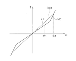
- Torsional characteristic diagram of a dynamic damper The figure which shows the relationship between an engine speed, an output side torque fluctuation
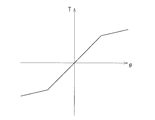
- the torsional characteristic diagram of the dynamic damper by other embodiment.
- the torsional characteristic diagram of the dynamic damper by other embodiment.
- the torsional characteristic diagram of the dynamic damper by other embodiment.
- a torque converter 1 as a fluid type power transmission device is shown in FIG.
- An engine (not shown) is arranged on the left side of FIG. 1, and a transmission (not shown) is arranged on the right side of FIG.
- a line OO shown in FIG. 1 is a rotation axis of the torque converter 1.
- the torque converter 1 is a device for transmitting power from an engine crankshaft (not shown) to an input shaft of a transmission.
- the torque converter 1 mainly includes a front cover 2 to which power is input, an impeller 3, a turbine 4, a stator 5, a lockup device 6, and a dynamic damper 7.
- the impeller 3, the turbine 4, and the stator 5 constitute a torque converter main body (fluid coupling main body) 8.
- FIG. 1 Front cover 2
- An impeller 3 is fixed to the front cover 2, and a fluid chamber is formed by the front cover 2 and the impeller 3.
- the turbine 4 is disposed so as to face the impeller 3 in the fluid chamber.
- the turbine 4 includes a turbine shell 10, a plurality of turbine blades 11 provided inside the turbine shell 10, and a turbine hub 13 fixed to the turbine shell 10 by rivets 12.
- the stator 5 is a mechanism for adjusting the flow of hydraulic oil from the turbine 4 to the impeller 3, and is disposed between the inner peripheral portion of the impeller 3 and the inner peripheral portion of the turbine 4.
- the turbine hub 13 has a spline hole 13a at the center, and an input shaft 15 of the transmission can be engaged with the spline hole 13a. Further, the turbine hub 13 includes a flange portion 13b extending to the outer peripheral side and a cylindrical portion 13c extending from the outer peripheral portion of the flange portion 13b to the front cover 2 side. As described above, the inner peripheral portion of the turbine shell 10 is fixed to the flange portion 13b by the rivets 12. The cylindrical portion 13c is formed with a protrusion 13d that protrudes further from the outer peripheral surface to the outer peripheral side.
- FIG. 2 shows the lock-up device 6 extracted.
- the lockup device 6 is a device for mechanically connecting the front cover 2 and the turbine 4 as necessary, and is disposed between the front cover 2 and the turbine 4.
- the lockup device 6 includes a piston 18, a drive plate 19, an output plate 20 (output side member), and a plurality of coil springs 21 (elastic members).
- the piston 18 is disposed between the front cover 2 and the turbine 4 so as to be axially movable.
- the piston 18 includes a disk-shaped main body portion 18a, an inner peripheral cylindrical portion 18b extending from the inner peripheral end of the main body portion 18a to the turbine 4 side, and an outer peripheral cylindrical shape extending from the outer peripheral end of the main body portion 18a to the turbine 4 side. Part 18c.
- the main body 18a is disposed to face the front cover 2.
- An annular friction member 23 is fixed to the side surface on the front cover 2 side in the outer peripheral portion of the main body portion 18a.
- the inner peripheral cylindrical portion 18b is supported on the outer peripheral surface of the cylindrical portion 13c of the turbine hub 13 so as to be movable in the axial direction and the rotational direction.
- a seal member 24 is disposed on the outer peripheral surface of the cylindrical portion 13 c of the turbine hub 13. Thereby, the space between the inner peripheral cylindrical portion 18b of the piston 18 and the outer peripheral surface of the cylindrical portion 13c of the turbine hub 13 is sealed. Note that the tip of the inner peripheral cylindrical portion 18b can abut on the protrusion 13d of the turbine hub 13, and the movement of the piston 18 toward the turbine 4 is restricted by the protrusion 13d.
- the drive plate 19 is disposed on the outer peripheral portion of the piston 18 on the turbine 4 side of the piston 18.
- the drive plate 19 is disposed on the inner peripheral side of the outer peripheral cylindrical portion 18 c of the piston 18.
- the drive plate 19 is formed in an annular shape, and includes a fixed portion 19a, a plurality of spring accommodating portions 19b, and a plurality of engaging portions 19c.
- the fixing portion 19 a is formed at the inner peripheral end of the drive plate 19 and is fixed to the piston 18 by a rivet 26.
- the spring accommodating portions 19b and the engaging portions 19c are alternately arranged in the circumferential direction.
- the spring accommodating portion 19b has a C-shaped cross section, and the coil spring 21 is accommodated therein.
- the engaging portion 19 c has a C-shaped cross section, and a part on the inner peripheral side and a part on the outer peripheral side are engaged with both ends of the coil spring 21.
- the power transmitted to the piston 18 by the engaging portion 19 c is transmitted to the coil spring 21 via the drive plate 19.
- the output plate 20 is formed in a disk shape and is disposed between the piston 18 and the turbine 4. An inner peripheral end portion of the output plate 20 is fixed to a flange portion 13 b of the turbine hub 13 together with the turbine shell 10 by a rivet 12. A plurality of engaging portions 20 a formed by bending toward the front cover 2 are provided at the outer peripheral end of the output plate 20. The plurality of engaging portions 20 a are engaged with both ends of the coil spring 21.
- the coil spring 21 elastically connects the piston 18 and the drive plate 19 and the output plate 20 in the rotational direction. As described above, the coil spring 21 is accommodated and supported in the spring accommodating portion 19b of the drive plate 19.
- the dynamic damper 7 is a device for attenuating rotational speed fluctuations from the engine, and is disposed between the output plate 20 and the impeller 3 as shown in FIGS. 1, 3, and 4.
- the dynamic damper 7 includes a base plate 28, first and second inertia rings 29 and 30, first and second lid members 31 and 32, an elastic unit 33, and a stop pin 34 (see FIG. 4). is doing.
- FIG. 4 is a diagram of the dynamic damper 7 viewed from the transmission side.
- the base plate 28 is formed in a disc shape, and an inner peripheral end portion is fixed to a radially intermediate portion of the output plate 20 by a rivet 36.
- the outer peripheral portion of the base plate 28 is formed to be biased toward the transmission side in the axial direction from the inner peripheral end portion.
- the base plate 28 has a plurality of spring accommodating portions 28a (openings) at predetermined intervals in the circumferential direction.
- the spring accommodating portion 28a has a predetermined length in the circumferential direction.
- a plurality of elongated holes 28b are formed between the circumferential directions of the plurality of spring accommodating portions 28a.
- the long hole 28b has a predetermined length in the circumferential direction, and is formed on the same circumference as the spring accommodating portion 28a.
- the first and second inertia rings 29 and 30 are formed by pressing a sheet metal member.
- the first inertia ring 29 is disposed between the outer periphery of the output plate 20 and the outer periphery of the base plate 28.
- the second inertia ring 30 is disposed on the transmission side of the base plate 28.
- the outer diameter of the first inertia ring 29 is the same as that of the second inertia ring 30, but the inner diameter is smaller than that of the second inertia ring 30.
- the first and second inertia rings 29, 30 have a plurality of spring accommodating portions 29a, 30a (openings) at predetermined intervals in the circumferential direction.
- the first inertia ring 29 and the second inertia ring 30 have different inner diameters, but in FIG.
- the spring accommodating portions 29 a and 30 a are formed at positions corresponding to the spring accommodating portion 28 a of the base plate 28.
- the first and second inertia rings 29, 30 have through holes 29 b, 30 b at positions corresponding to the circumferential center positions of the long holes 28 b of the base plate 28.
- the first lid member 31 is disposed further on the engine side than the first inertia ring 29 on the engine side.
- the first lid member 31 is an annular member and has an inner diameter that is smaller than the inner diameter of the first inertia ring 29.
- the first lid member 31 has through holes 31 b at positions corresponding to the through holes 29 b and 30 b of the first and second inertia rings 29 and 30. 7 is a cross-sectional view taken along line VII-VII in FIG.
- the second lid member 32 is disposed further on the transmission side of the second inertia ring 30.
- the second lid member 32 is an annular member and has the same inner diameter as that of the second inertia ring 30.
- a through hole 32 b is formed in the second lid member 32 at a position corresponding to the through holes 29 b and 30 b of the first and second inertia rings 29 and 30.
- the elastic unit 33 includes large and small coil springs 33 a and 33 b housed in the spring housing portion 28 a of the base plate 28 and the spring housing portions 29 a and 30 a of the first and second inertia rings 29 and 30. It is configured.
- the large coil spring 33a has substantially the same length as the circumferential length of the spring accommodating portion 28a. Therefore, both ends of the large coil spring 33a are in contact with the circumferential ends of the spring accommodating portions 28a, 29a, 30a.
- the small coil spring 33b is disposed inside the large coil spring 33a and is set shorter than the length of the large coil spring 33a. For this reason, the small coil spring 33b operates later than the operation of the large coil spring 33a.
- the stop pin 34 has a large-diameter barrel portion 34 a at the center in the axial direction, and small-diameter barrel portions 34 b on both sides thereof.
- the large-diameter trunk portion 34a has a larger diameter than the through holes 29b and 30b of the first and second inertia rings 29 and 30, and a smaller diameter than the diameter (radial dimension) of the long hole 28b of the base plate 28.
- the thickness of the large-diameter trunk portion 34 a is slightly smaller than the thickness of the base plate 28.
- the small-diameter body portion 34b is inserted through the through holes 29b, 30b of the first and second inertia rings 29, 30 and the through holes 31b, 32b of the first and second lid members 31, 32.
- the inertia rings 29 and 30 and the lid members 31 and 32 are fixed to both sides of the base plate 28 in the axial direction by caulking the head of the small-diameter barrel portion 34b.
- the base plate 28, the two inertia rings 29, 30 and the two lid members 31, 32 (hereinafter, the first and second inertia rings 29, 30 and the first and second lid members 31, 32 and "inertia I"), relative rotation is possible within a range in which the stop pin 34 can move in the long hole 28b of the base plate 28. And when the large diameter trunk
- the dynamic damper 7 fixed to the output plate 20 is actuated by the rotation of the output plate 20, and the operation of the dynamic damper 7 suppresses fluctuations in the rotational speed of the engine. That is, the rotation of the base plate 28 and the rotation of the inertial body I cause a phase shift due to the action of the elastic unit 33. Specifically, the inertial body I fluctuates at a phase that cancels out the fluctuation in the rotation speed of the base plate 28 at a predetermined engine speed. Due to this phase shift, the rotational speed fluctuation of the transmission can be absorbed.
- the dynamic damper 7 when relative rotation occurs between the base plate 28 and the inertial body I, only the large coil spring 33 a is first compressed, and a low-rigidity torsion characteristic (first-stage torsional characteristic)
- the dynamic damper 7 is operated by the twist characteristics, the torsional rigidity k1) of FIG.
- the dynamic damper 7 operates with a torsion characteristic having higher rigidity than that of the first-stage torsion characteristic (second-stage torsion characteristic, torsional rigidity k2 in FIG. 8).
- the equivalent rigidity of the dynamic damper 7 is keq indicated by a broken line in FIG.
- FIG. 9 shows the relationship between the engine speed (frequency), the torsion angle of the dynamic damper 7 and the torque fluctuation transmitted to the transmission side.
- the torsion angle is relatively small ⁇ 1 in the region where the engine speed is low. Further, in the region where the engine speed is high, the twisting angle becomes a larger ⁇ 2.
- Fqa is a resonance frequency (natural frequency) at which the base plate 28 and the inertia rings 29 and 30 vibrate in opposite phases and the vibration of the base plate 28 is lowest when the rigidity of the dynamic damper 7 is k1.
- Fqb is a peak frequency at which the inertia rings 29 and 30 amplify the vibration of the base plate 28 when the rigidity of the dynamic damper 7 is k1.
- the torsional characteristics of the dynamic damper 7 are set in two stages as shown in FIG. 8 so that the torsional characteristics are nonlinear over the entire operating range of the dynamic damper 7.
- the peak PH appearing in the high rotation speed range can be moved to the high rotation speed side from the normal rotation speed range by appropriately setting the two-stage characteristics in consideration of the engine specifications and the like. That is, by setting the torsional characteristics of the dynamic damper 7 to two stages and setting its equivalent rigidity to keq, the peak PH can be moved to the high speed side, and the torque fluctuation at the frequency Fqb can be attenuated.
- the characteristic B in this case is indicated by a one-dot chain line.
- the elastic unit 33 is composed of the large and small coil springs 33a and 33b accommodated in the single spring accommodating portion 28a, but the configuration of the elastic unit is not limited to this.
- the first coil spring 41a is disposed in one spring housing portion 28a
- the second coil spring 41b having a shorter length than the first coil spring 41a is disposed in another spring housing portion 28a. May be.
- the torsional characteristics are made two stages, but two or more stages of torsional characteristics may be used.
- the low-angle region has low torsional characteristics and the high-angle region has high-rigidity torsional characteristics.
- the frequency is Fqa
- the vibration is effectively reduced by the rigidity of the first stage
- the frequency is Fqb
- the torsion angle of the dynamic damper is increased and the rigidity of the dynamic damper is decreased.
- the peak PH moves to the low rotation side, and the peak PH does not substantially appear.
- the elastic unit may be constituted by a rubber elastic member.
- An example of torsional characteristics in this case is shown in FIG. Even with such a configuration, the torsional characteristics of the dynamic damper can be made non-linear.
- An initial torque may be applied to the torsion characteristics to make the torsion characteristics non-linear.
- the coil spring may be set in a state of being previously compressed in the spring accommodating portion.
- the torsional torque of the inertia rings 29 and 30 and the lid members 31 and 32 with respect to the base plate 28 becomes a predetermined value or more, the coil spring starts to be elastically deformed.
- the torsional characteristics in this case are shown in FIG.
- the torsional characteristics may be curved. Specifically, the pitch of the coil springs is made unequal, and the line is gradually brought into close contact with the torsion angle so that the rigidity becomes higher as the torsion angle increases.
- the clutch portion is constituted by the piston and the friction member, but it may be a multi-plate type clutch portion having a plurality of clutch plates.
Landscapes
- Engineering & Computer Science (AREA)
- General Engineering & Computer Science (AREA)
- Mechanical Engineering (AREA)
- Physics & Mathematics (AREA)
- Acoustics & Sound (AREA)
- Aviation & Aerospace Engineering (AREA)
- Mechanical Operated Clutches (AREA)
- Vibration Dampers (AREA)
Abstract
Description
流体式動力伝達装置としてのトルクコンバータ1を図1に示す。図1の左側にエンジン(図示せず)が配置され、図1の右側にトランスミッション(図示せず)が配置されている。図1に示す線O-Oは、トルクコンバータ1の回転軸線である。
フロントカバー2にはインペラ3が固定されており、フロントカバー2とインペラ3とにより流体室が形成されている。タービン4は流体室内でインペラ3に対向するように配置されている。タービン4は、タービンシェル10と、タービンシェル10の内部に設けられた複数のタービンブレード11と、リベット12によりタービンシェル10に固定されたタービンハブ13と、を有している。ステータ5は、タービン4からインペラ3への作動油の流れを調節するための機構であり、インペラ3の内周部とタービン4の内周部との間に配置されている。
図2にロックアップ装置6を抽出して示している。ロックアップ装置6は、必要に応じてフロントカバー2とタービン4とを機械的に連結するための装置であり、フロントカバー2とタービン4との間に配置されている。ロックアップ装置6は、ピストン18と、ドライブプレート19と、出力プレート20(出力側部材)と、複数のコイルスプリング21(弾性部材)と、を有している。
ピストン18はフロントカバー2とタービン4との間に軸方向移動自在に配置されている。ピストン18は、円板状の本体部18aと、本体部18aの内周端からタービン4側に延びる内周筒状部18bと、本体部18aの外周端からをタービン4側に延びる外周筒状部18cと、を有している。
ドライブプレート19は、ピストン18のタービン4側において、ピストン18の外周部に配置されている。また、ドライブプレート19はピストン18の外周筒状部18cの内周側に配置されている。ドライブプレート19は、環状に形成されており、固定部19aと、複数のスプリング収容部19bと、複数の係合部19cと、を有している。
出力プレート20は、円板状に形成されており、ピストン18とタービン4との間に配置されている。出力プレート20の内周端部はリベット12によってタービンシェル10とともにタービンハブ13のフランジ部13bに固定されている。出力プレート20の外周端部には、フロントカバー2側に折り曲げて形成された複数の係合部20aが設けられている。複数の係合部20aはコイルスプリング21の両端に係合している。
コイルスプリング21は、ピストン18及びドライブプレート19と出力プレート20とを回転方向に弾性的に連結する。コイルスプリング21は、前述のように、ドライブプレート19のスプリング収容部19bに収容されて支持されている。
ダイナミックダンパ7は、エンジンからの回転速度変動を減衰するための装置であり、図1、図3、及び図4に示すように、出力プレート20とインペラ3との間に配置されている。ダイナミックダンパ7は、ベースプレート28と、第1及び第2イナーシャリング29,30と、第1及び第2蓋部材31,32と、弾性ユニット33と、ストップピン34(図4参照)と、を有している。なお、図4はダイナミックダンパ7をトランスミッション側から視た図である。
ベースプレート28の一部を図5に示している。図3及び図5に示すように、ベースプレート28は、円板状に形成されており、内周端部がリベット36によって出力プレート20の径方向中間部に固定されている。ベースプレート28の外周部は、内周端部から軸方向においてトランスミッション側に偏倚して形成されている。ベースプレート28は、図5に示すように、円周方向に所定の間隔で、複数のスプリング収容部28a(開口)を有している。スプリング収容部28aは円周方向に所定の長さを有している。複数のスプリング収容部28aの円周方向間には、複数の長孔28bが形成されている。長孔28bは、円周方向に所定の長さを有し、スプリング収容部28aと同じ円周上に形成されている。
第1及び第2イナーシャリング29,30は、板金部材をプレス加工して形成されたものである。第1イナーシャリング29は出力プレート20の外周部とベースプレート28の外周部との間に配置されている。第2イナーシャリング30は、ベースプレート28のトランスミッション側に配置されている。第1イナーシャリング29の外径は第2イナーシャリング30と同じであるが、内径は第2イナーシャリング30よりも小径である。
第1蓋部材31はエンジン側の第1イナーシャリング29のさらにエンジン側に配置されている。第1蓋部材31は、環状の部材であり、内径は第1イナーシャリング29の内径よりさらに小さい。図7に示すように、第1蓋部材31には、第1及び第2イナーシャリング29,30の貫通孔29b,30bに対応する位置に貫通孔31bが形成されている。なお、図7は図4のVII-VII線断面図である。
弾性ユニット33は、図4に示すように、ベースプレート28のスプリング収容部28aと第1及び第2イナーシャリング29,30のスプリング収容部29a,30aとに収納された大小のコイルスプリング33a,33bから構成されている。大コイルスプリング33aはスプリング収容部28aの円周方向長さとほぼ同じ長さを有している。したがって、大コイルスプリング33aの両端部は各スプリング収容部28a,29a,30aの円周方向端部に当接している。また、小コイルスプリング33bは、大コイルスプリング33aの内部に配置され、大コイルスプリング33aの長さより短く設定されている。このため、小コイルスプリング33bは大コイルスプリング33aの作動より遅れて作動する。
ストップピン34は、図7に示すように、軸方向の中央部に大径胴部34aを有し、その両側に小径胴部34bを有している。
まず、トルクコンバータ本体の動作について簡単に説明する。フロントカバー2及びインペラ3が回転している状態では、インペラ3からタービン4へ作動油が流れ、作動油を介してインペラ3からタービン4へ動力が伝達される。タービン4に伝達された動力はタービンハブ13を介してトランスミッションの入力シャフト15に伝達される。
出力プレート20の回転によって、出力プレート20に固定されたダイナミックダンパ7が作動し、このダイナミックダンパ7の作用によってエンジンの回転速度変動が抑制される。すなわち、ベースプレート28の回転と慣性体Iの回転とは、弾性ユニット33の作用によって位相にズレが生じる。具体的には、所定のエンジン回転数において慣性体Iはベースプレート28の回転速度変動を打ち消す位相で変動する。この位相のズレによって、トランスミッションの回転速度変動を吸収することができる。
本発明は以上のような実施形態に限定されるものではなく、本発明の範囲を逸脱することなく種々の変形又は修正が可能である。
2 フロントカバー
4 タービン
6 ロックアップ装置
7 ダイナミックダンパ
8 トルクコンバータ本体
20 出力プレート(出力側部材)
21 コイルスプリング(弾性部材)
28 ベースプレート
28a スプリング収容部(開口)
29,30 イナーシャリング
29a,30a スプリング収容部(開口)
31,32 蓋部材
33 弾性ユニット
33a,大スプリング
33b 小スプリング
Claims (7)
- エンジンからトランスミッションへ流体を介して動力を伝達するための流体式動力伝達装置であって、
フロントカバーと、
前記トランスミッションの入力シャフトと一体回転可能に設けられたタービンを含み、前記エンジンからの動力を前記トランスミッションに流体を介して伝達する流体継手本体と、
前記フロントカバーと前記タービンとの間に設けられ、前記フロントカバーからの動力を伝達又は遮断するクラッチ部と、前記クラッチ部から動力が伝達され前記タービンに連結された出力側部材と、を有するロックアップ装置と、
前記ロックアップ装置の出力側部材に固定され、前記エンジンからの回転速度変動を減衰するためのダイナミックダンパと、
を備え、
前記ダイナミックダンパは、
前記ロックアップ装置の出力側部材に固定されたベースプレートと、
前記ベースプレートと回転方向に相対移動が可能な慣性体と、
非線形の捩じり特性を有し、前記ベースプレートと前記慣性体とを回転方向に弾性的に連結する弾性ユニットと、
を有する、
流体式動力伝達装置。 - 前記弾性ユニットは、
第1捩じり角度領域では第1捩じり剛性を有し、
前記第1捩じり角度領域より大きい第2捩じり角度領域では前記第1捩じり剛性と異なる第2剛性を有する、
請求項1に記載の流体式動力伝達装置。 - 前記弾性ユニットは、
第1捩じり角度領域で作動する第1弾性部材と、
前記第1捩じり角度領域より大きい第2捩じり角度領域でのみ作動する第2弾性部材と、
を有している、
請求項1又は2に記載の流体式動力伝達装置。 - 前記弾性ユニットは、互いに剛性の異なる少なくとも2種類の弾性部材を有する、請求項1から3のいずれかに記載の流体式動力伝達装置。
- 前記弾性ユニットは、前記ベースプレートに対する前記慣性体の捩じりトルクが所定値以上で弾性変形を開始するように予圧状態で装着されている、請求項1から4のいずれかに記載の流体式動力伝達装置。
- 前記弾性ユニットは、ゴムにより形成された弾性部材を有している、請求項1から5のいずれかに記載の流体式動力伝達装置。
- 前記ベースプレートは、環状に形成されるとともに、外周部に円周方向に所定の間隔で複数の開口を有し、
前記慣性体は、
前記ベースプレートの外周部を軸方向に挟むように配置され、それぞれ環状に形成されるとともに前記ベースプレートの開口に対応する位置に開口を有する第1イナーシャリング及び第2イナーシャリングと、
それぞれ前記第1イナーシャリング及び前記第2イナーシャリングの前記ベースプレートと逆側に配置され、前記第1及び第2イナーシャリングの開口を塞ぐように配置された第1蓋部材及び第2蓋部材と、
を有し、
前記弾性ユニットは前記ベースプレートと前記第1及び第2イナーシャリングの開口に収容された複数の弾性部材を有する、
請求項1から6のいずれかに記載の流体式動力伝達装置。
Priority Applications (4)
| Application Number | Priority Date | Filing Date | Title |
|---|---|---|---|
| KR1020167028917A KR20170002387A (ko) | 2014-05-07 | 2015-01-23 | 유체식 동력 전달 장치 |
| MX2016011255A MX380214B (es) | 2014-05-07 | 2015-01-23 | Dispositivo de transmisión de energía de fluido. |
| CN201580000072.9A CN105247246B (zh) | 2014-05-07 | 2015-01-23 | 流体式动力传递装置 |
| US14/647,006 US9618105B2 (en) | 2014-05-07 | 2015-01-23 | Fluid power transmission device |
Applications Claiming Priority (2)
| Application Number | Priority Date | Filing Date | Title |
|---|---|---|---|
| JP2014095817A JP5852701B2 (ja) | 2014-05-07 | 2014-05-07 | 流体式動力伝達装置 |
| JP2014-095817 | 2014-05-07 |
Publications (1)
| Publication Number | Publication Date |
|---|---|
| WO2015170485A1 true WO2015170485A1 (ja) | 2015-11-12 |
Family
ID=54392340
Family Applications (1)
| Application Number | Title | Priority Date | Filing Date |
|---|---|---|---|
| PCT/JP2015/051935 Ceased WO2015170485A1 (ja) | 2014-05-07 | 2015-01-23 | 流体式動力伝達装置 |
Country Status (6)
| Country | Link |
|---|---|
| US (1) | US9618105B2 (ja) |
| JP (1) | JP5852701B2 (ja) |
| KR (1) | KR20170002387A (ja) |
| CN (1) | CN105247246B (ja) |
| MX (1) | MX380214B (ja) |
| WO (1) | WO2015170485A1 (ja) |
Families Citing this family (18)
| Publication number | Priority date | Publication date | Assignee | Title |
|---|---|---|---|---|
| DE102014211597A1 (de) * | 2014-06-17 | 2015-12-17 | Schaeffler Technologies AG & Co. KG | Fliehkraftpendel |
| FR3037626B1 (fr) * | 2015-06-18 | 2018-08-10 | Valeo Embrayages | Dispositif de filtration des vibrations |
| JP6182192B2 (ja) * | 2015-10-16 | 2017-08-16 | 株式会社ユタカ技研 | 流体式動力伝達装置 |
| JP6505035B2 (ja) | 2016-03-01 | 2019-04-24 | 本田技研工業株式会社 | トルク伝達装置 |
| DE112017000348T5 (de) * | 2016-03-16 | 2018-09-27 | Aisin Aw Co., Ltd. | Dämpfervorrichtung |
| JP6637802B2 (ja) | 2016-03-18 | 2020-01-29 | 株式会社エクセディ | 振動低減装置 |
| CN110494672A (zh) * | 2017-04-28 | 2019-11-22 | 爱信艾达株式会社 | 振动衰减装置 |
| JP6965625B2 (ja) * | 2017-08-14 | 2021-11-10 | 株式会社アイシン | 振動減衰装置 |
| KR102290314B1 (ko) * | 2018-12-28 | 2021-08-18 | 주식회사 카펙발레오 | 토크 컨버터 |
| US11549567B2 (en) | 2018-12-28 | 2023-01-10 | Valeo Kapec Co., Ltd. | Lock-up device for torque converter |
| JP7218206B2 (ja) * | 2019-02-19 | 2023-02-06 | 株式会社エクセディ | ダンパ装置 |
| JP7211844B2 (ja) * | 2019-02-19 | 2023-01-24 | 株式会社エクセディ | ダンパ装置 |
| JP7218205B2 (ja) * | 2019-02-19 | 2023-02-06 | 株式会社エクセディ | ダイナミックダンパ装置 |
| JP2020200908A (ja) * | 2019-06-12 | 2020-12-17 | 株式会社ユタカ技研 | 動力伝達装置 |
| US11767899B2 (en) | 2019-06-12 | 2023-09-26 | Yutaka Giken Co., Ltd. | Power transmission device |
| EP4133192A1 (en) * | 2020-04-10 | 2023-02-15 | Lord Corporation | Multiple stage torsional coupling with centering bearing and coil spring snubbing |
| KR20230014322A (ko) * | 2021-07-21 | 2023-01-30 | 주식회사 카펙발레오 | 차량용 토크 컨버터 |
| PL445312A1 (pl) * | 2023-06-21 | 2024-12-23 | Politechnika Śląska | Wiskotyczny stabilizator prędkości obrotowej układów napędowych maszyn |
Citations (5)
| Publication number | Priority date | Publication date | Assignee | Title |
|---|---|---|---|---|
| JPH09264399A (ja) * | 1996-01-26 | 1997-10-07 | Toyota Motor Corp | 流体伝動装置 |
| JPH10238611A (ja) * | 1997-02-25 | 1998-09-08 | Exedy Corp | トルクコンバータのロックアップダンパー |
| JP2004278744A (ja) * | 2003-03-18 | 2004-10-07 | Exedy Corp | ダンパー機構及びダンパーディスク組立体 |
| JP2013036587A (ja) * | 2011-08-10 | 2013-02-21 | Aisin Aw Industries Co Ltd | 流体式トルク伝達装置 |
| JP2013506100A (ja) * | 2009-09-28 | 2013-02-21 | シェフラー テクノロジーズ アクチエンゲゼルシャフト ウント コンパニー コマンディートゲゼルシャフト | 動吸振器とねじり振動ダンパとを備えたハイドロダイナミック式のトルクコンバータ |
Family Cites Families (12)
| Publication number | Priority date | Publication date | Assignee | Title |
|---|---|---|---|---|
| JPS58106246A (ja) * | 1981-12-16 | 1983-06-24 | Atsugi Motor Parts Co Ltd | 回転トルク伝達装置 |
| JPS604628A (ja) * | 1983-06-23 | 1985-01-11 | Daikin Mfg Co Ltd | 薄肉型ダンパ−デイスク |
| JPS63251661A (ja) * | 1987-04-08 | 1988-10-19 | Daikin Mfg Co Ltd | トルクコンバ−タ用のダンパ−装置 |
| EP0732527B1 (en) * | 1995-03-17 | 2002-06-12 | Toyota Jidosha Kabushiki Kaisha | Hydrokinetic torque converter with lock-up clutch and internal vibration damping |
| US5941354A (en) | 1996-11-26 | 1999-08-24 | Exedy Corporation | Lockup damper of torque converter |
| JP5473933B2 (ja) * | 2007-11-29 | 2014-04-16 | シェフラー テクノロジーズ アクチエンゲゼルシャフト ウント コンパニー コマンディートゲゼルシャフト | 回転数適応型の動吸振器を備えた力伝達装置および減衰特性を改善するための方法 |
| JP4648428B2 (ja) | 2008-06-03 | 2011-03-09 | 株式会社エクセディ | 流体式動力伝達装置 |
| JP2011058557A (ja) | 2009-09-09 | 2011-03-24 | Exedy Corp | 振動減衰装置、ロックアップ装置および流体式動力伝達装置 |
| JP5684515B2 (ja) * | 2010-08-20 | 2015-03-11 | 株式会社エクセディ | トルクコンバータ |
| JP5326008B2 (ja) * | 2012-02-07 | 2013-10-30 | 株式会社エクセディ | ダイナミックダンパ装置及び流体式動力伝達装置のロックアップ装置 |
| KR20140030762A (ko) * | 2012-09-03 | 2014-03-12 | 현대자동차주식회사 | 토크 컨버터의 유압제어회로 |
| CN103244634A (zh) * | 2013-05-21 | 2013-08-14 | 广西柳工机械股份有限公司 | 新型双涡轮液力变矩器 |
-
2014
- 2014-05-07 JP JP2014095817A patent/JP5852701B2/ja active Active
-
2015
- 2015-01-23 KR KR1020167028917A patent/KR20170002387A/ko not_active Ceased
- 2015-01-23 WO PCT/JP2015/051935 patent/WO2015170485A1/ja not_active Ceased
- 2015-01-23 CN CN201580000072.9A patent/CN105247246B/zh active Active
- 2015-01-23 US US14/647,006 patent/US9618105B2/en active Active
- 2015-01-23 MX MX2016011255A patent/MX380214B/es unknown
Patent Citations (5)
| Publication number | Priority date | Publication date | Assignee | Title |
|---|---|---|---|---|
| JPH09264399A (ja) * | 1996-01-26 | 1997-10-07 | Toyota Motor Corp | 流体伝動装置 |
| JPH10238611A (ja) * | 1997-02-25 | 1998-09-08 | Exedy Corp | トルクコンバータのロックアップダンパー |
| JP2004278744A (ja) * | 2003-03-18 | 2004-10-07 | Exedy Corp | ダンパー機構及びダンパーディスク組立体 |
| JP2013506100A (ja) * | 2009-09-28 | 2013-02-21 | シェフラー テクノロジーズ アクチエンゲゼルシャフト ウント コンパニー コマンディートゲゼルシャフト | 動吸振器とねじり振動ダンパとを備えたハイドロダイナミック式のトルクコンバータ |
| JP2013036587A (ja) * | 2011-08-10 | 2013-02-21 | Aisin Aw Industries Co Ltd | 流体式トルク伝達装置 |
Also Published As
| Publication number | Publication date |
|---|---|
| KR20170002387A (ko) | 2017-01-06 |
| US9618105B2 (en) | 2017-04-11 |
| CN105247246A (zh) | 2016-01-13 |
| US20160258521A1 (en) | 2016-09-08 |
| JP5852701B2 (ja) | 2016-02-03 |
| CN105247246B (zh) | 2018-11-23 |
| MX380214B (es) | 2025-03-12 |
| MX2016011255A (es) | 2016-11-30 |
| JP2015212568A (ja) | 2015-11-26 |
Similar Documents
| Publication | Publication Date | Title |
|---|---|---|
| JP5852701B2 (ja) | 流体式動力伝達装置 | |
| JP6334284B2 (ja) | 動力伝達装置及びトルクコンバータのロックアップ装置 | |
| JP5878893B2 (ja) | トルクコンバータのロックアップ装置 | |
| JP4773553B2 (ja) | トルクコンバータ用ロックアップ装置 | |
| JP4755277B2 (ja) | トルクコンバータ用ロックアップ装置 | |
| JP2011122622A (ja) | トルクコンバータ用ロックアップ装置 | |
| CN105209793B (zh) | 液力变矩器的锁定装置 | |
| JP6252458B2 (ja) | ダンパ装置 | |
| JP5791772B1 (ja) | 流体式動力伝達装置 | |
| JP2017166666A (ja) | 振動低減装置 | |
| JP6182434B2 (ja) | トルクコンバータのロックアップ装置 | |
| WO2016103890A1 (ja) | 動力伝達装置及びトルクコンバータのロックアップ装置 | |
| JP5791773B1 (ja) | 流体式動力伝達装置 | |
| JP6605280B2 (ja) | ダンパ装置 | |
| JP4684348B1 (ja) | ダンパ装置 | |
| JP5688113B2 (ja) | トルクコンバータ用のロックアップ装置 | |
| CN107208768B (zh) | 液力变矩器的锁定装置 | |
| JP6287763B2 (ja) | 発進装置 |
Legal Events
| Date | Code | Title | Description |
|---|---|---|---|
| WWE | Wipo information: entry into national phase |
Ref document number: 201580000072.9 Country of ref document: CN |
|
| WWE | Wipo information: entry into national phase |
Ref document number: 14647006 Country of ref document: US |
|
| 121 | Ep: the epo has been informed by wipo that ep was designated in this application |
Ref document number: 15788640 Country of ref document: EP Kind code of ref document: A1 |
|
| WWE | Wipo information: entry into national phase |
Ref document number: MX/A/2016/011255 Country of ref document: MX |
|
| ENP | Entry into the national phase |
Ref document number: 20167028917 Country of ref document: KR Kind code of ref document: A |
|
| NENP | Non-entry into the national phase |
Ref country code: DE |
|
| 122 | Ep: pct application non-entry in european phase |
Ref document number: 15788640 Country of ref document: EP Kind code of ref document: A1 |