WO2015166767A1 - 模型 - Google Patents
模型 Download PDFInfo
- Publication number
- WO2015166767A1 WO2015166767A1 PCT/JP2015/060637 JP2015060637W WO2015166767A1 WO 2015166767 A1 WO2015166767 A1 WO 2015166767A1 JP 2015060637 W JP2015060637 W JP 2015060637W WO 2015166767 A1 WO2015166767 A1 WO 2015166767A1
- Authority
- WO
- WIPO (PCT)
- Prior art keywords
- outer member
- lower arm
- inner member
- model
- joint
- Prior art date
- Legal status (The legal status is an assumption and is not a legal conclusion. Google has not performed a legal analysis and makes no representation as to the accuracy of the status listed.)
- Ceased
Links
Images




Classifications
-
- A—HUMAN NECESSITIES
- A63—SPORTS; GAMES; AMUSEMENTS
- A63H—TOYS, e.g. TOPS, DOLLS, HOOPS OR BUILDING BLOCKS
- A63H3/00—Dolls
- A63H3/36—Details; Accessories
- A63H3/46—Connections for limbs
Definitions
- the present invention relates to a model.
- a model including a first part and a second part and a joint part that rotatably connects the second part to the first part is known (for example, see Patent Document 1).
- the upper leg portion 15 is divided into two parts, and a pin (not shown) provided on the inner surface of one divided body and a boss 25b provided on the inner surface of the other divided body are fitted and assembled.
- the lower leg portion 16 is also divided into two like the upper leg portion 15, and a pin (not shown) provided on the inner surface of one divided body and a boss 26a provided on the inner surface of the other divided body are fitted. Assembled.
- the knee joint member 5 is provided with a hole 51a through which the boss 25b is inserted and a hole 52a through which the boss 26a is inserted.
- the boss 25b is inserted into the hole 51a of the knee joint member 5, the boss 26a is inserted into the hole 52a of the knee joint member 5, and the upper leg 15 and the lower leg 16 are assembled.
- 15 is connected to the upper leg 15 via the knee joint member 5 so as to be rotatable with respect to the arm 15.
- Both ends of the boss 26a serving as a pivot shaft of the lower leg portion 16 are supported by two divided bodies constituting the lower leg portion 16, and the knee joint member 5 is sandwiched between the two divided bodies and is prevented from coming off from the boss 26a.
- the knee joint member 5 is sandwiched between two divided bodies constituting the lower leg portion 16 and is prevented from coming off from the boss 26a.
- Strength is required for joining.
- the two divided bodies constituting the lower leg portion 16 are joined by fitting the bosses 26a provided in one divided body and the pins provided in the other divided body, thereby increasing the bonding strength of the two divided bodies.
- the boss 26a and the pin need to have a corresponding size. Therefore, it is difficult to reduce the size of the joint.
- the present invention has been made in view of the above-described circumstances, and an object thereof is to maintain the durability of the joint of the model and to reduce the size.
- the model according to the present invention includes a first portion and a second portion, and a joint portion that rotatably connects the second portion to the first portion, and the joint portion has a free end at one end.
- the second portion includes an inner member provided with a holding portion that rotatably holds an outer periphery of the rotating shaft portion, and an outer member into which the inner member is inserted.
- the outer member includes a pair of barrier portions that sandwich the rotating shaft portion in the axial direction of the rotating shaft portion that is held by the holding portion of the inner member that is inserted into the outer member. It is characterized by having.
- the second portion further includes an exterior member that covers an outer side of the outer member, and the inner member and the exterior member penetrate through the outer member and engage with each other. May be.
- the inner member is provided with an engaging convex portion
- the outer member is provided with a notch portion that exposes the engaging convex portion.
- the inner member has a side surface that faces the engaging convex portion in the direction of removal from the outer member, and the exterior member is interposed between the engaging convex portion and the side surface of the notch portion. You may have a latching piece.
- the inner member and the outer member are provided with holes that communicate with the inner member inserted into the outer member, and the outer member is the inner member. And you may have an engaging convex part inserted in the said hole of each said outer member.
- the durability of the joint of the model can be maintained and the size can be reduced.
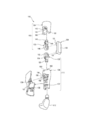
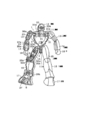
- FIG. 1 It is a front view which shows the external appearance of an example of a model for describing embodiment of this invention. It is a perspective view which shows the external appearance of the arm part of the model of FIG. It is an exploded view which shows the structure of the arm part of the model of FIG. It is a rear view which shows the structure of the arm part of the model of FIG. It is a side view which shows the structure of the arm part of the model of FIG. It is a rear view which shows the structure of the modification of the arm part of the model of FIG. It is a figure which shows the structure of the conventional model.
- FIG. 1 shows the appearance of an example of a model for explaining an embodiment of the present invention.
- the model 101 shown in FIG. 1 presents a doll as a whole, and includes a head 102, a torso 103, a waist 104, a pair of left and right arms 105, and a pair of left and right legs 106.
- the head portion 102 is connected to the trunk portion 103 via the neck joint portion 120
- the trunk portion 103 is connected to the waist portion 104 via the abdominal joint portion 121.
- the arm part 105 is connected to the trunk part 103 via the shoulder joint part 122
- the leg part 106 is connected to the waist part 104 via the hip joint part 123.
- the arm unit 105 includes an upper arm unit 110, a lower arm unit 111, and a hand unit 112.
- the upper arm part 110 is connected to the shoulder joint part 122.
- the lower arm portion 111 is connected to the upper arm portion 110 via the elbow joint portion 124.
- the hand portion 112 is connected to the lower arm portion 111.
- the lower arm portion 111 connected to the upper arm portion 110 via the elbow joint portion 124 has one degree of freedom of rotation and is configured to bend and extend with respect to the upper arm portion 110.
- the leg 106 has a thigh 113, a shin 114, and a foot 115.
- the thigh 113 is connected to the hip joint 123.
- the shin part 114 is connected to the thigh 113 through the knee joint part 125.
- the foot part 115 is connected to the shin part 114 via the ankle joint part 126.
- the shin part 114 connected to the thigh 113 via the knee joint part 125 has one degree of freedom of rotation and is configured to bend and stretch with respect to the thigh 113.
- the foot portion 115 connected to the shin portion 114 via the ankle joint portion 126 also has one degree of freedom of rotation and is configured to bend and stretch with respect to the shin portion 114.
- FIG. 2 shows the appearance of the arm 105.
- 3 to 5 show the configuration of the arm portion 105, respectively.
- the arm portion 105 includes the upper arm portion 110 (first portion), the lower arm portion 111 (second portion), the hand portion 112, and the elbow joint that rotatably connects the lower arm portion 111 to the upper arm portion 110. Part 124.
- the elbow joint portion 124 has a base portion 130 and rotation shaft portions 131 and 132.
- the pivot shaft portions 131 and 132 are provided to protrude from the base portion 130, and the distal ends of the pivot shaft portions 131 and 132 are free ends.
- the upper arm part 110 includes an upper arm inner member 133 and an upper arm outer member 134.
- the upper arm inner member 133 includes a holding portion 140 and a shaft portion 141 provided to extend from the holding portion 140.
- the holding part 140 is formed in a substantially annular shape through which the rotation shaft part 131 of the elbow joint part 124 can be inserted, and the holding part 140 through which the rotation shaft part 131 is inserted extends around the outer periphery of the rotation shaft part 131. Hold it pivotably.
- the upper arm outer member 134 is provided with a receiving hole 142 into which the shaft portion 141 of the upper arm inner member 133 is inserted.
- An engaging portion 143 that locks the shaft portion 141 inserted into the receiving hole 142 is provided on the inner peripheral surface of the receiving hole 142.
- the outer peripheral surface of the shaft portion 141 is locked by the engaging portion 143.
- An engaged portion 144 is provided.
- the engaging portion 143 is formed as an annular convex portion
- the engaged portion 144 is formed as an annular concave portion into which the engaging portion 143 is fitted.
- the rotation shaft portion 131 is rotatably held by the holding portion 140, and the elbow joint portion 124 is configured to be rotatable with respect to the upper arm portion 110, but the elbow joint portion 124 is configured.
- the rotation with respect to the upper arm part 110 is not essential, and the elbow joint part 124 may be formed integrally with the upper arm part 110.
- the lower arm portion 111 includes a lower arm inner member 135 and a lower arm outer member 136, and an exterior member 137 that covers the outer side of the lower arm outer member 136.
- the lower arm inner member 135 has a holding portion 150 and a shaft portion 151 provided extending from the holding portion 150.
- the holding part 150 is formed in a substantially annular shape through which the rotation shaft part 132 of the elbow joint part 124 can be inserted, and the holding part 150 through which the rotation shaft part 132 is inserted extends around the outer periphery of the rotation shaft part 132. Hold it pivotably.
- the lower arm outer member 136 is provided with a receiving hole 152 into which the shaft portion 151 of the lower arm inner member 135 is inserted.
- engaging and engaged portions are provided in the shaft portion 151 and the accommodation hole 152.
- the shaft portion 151 is prevented from coming out of the accommodation hole 152 by passing through the lower arm outer member 136 and engaging with the exterior member 137.
- the shaft portion 151 is provided with an engaging convex portion 154 that engages with the exterior member 137.
- a cutout portion 155 reaching the accommodation hole 152 is provided on the outer peripheral surface of the lower arm outer member 136, and the engagement convex portion 154 is formed in the cutout portion 155 in a state where the shaft portion 151 is inserted into the accommodation hole 152. Exposed through.
- the cutout portion 155 is provided with a side surface 156 that faces the engagement convex portion 154 in the direction in which the shaft portion 151 is removed from the accommodation hole 152, and there is a gap between the engagement convex portion 154 and the side surface 156. It is left.
- the exterior member 137 has a pair of holding portions 157 and 158, the lower arm outer member 136 is sandwiched between the both holding portions 157 and 158, and is attached to the lower arm outer member 136.
- One holding portion 157 is provided with a locking piece 159 that engages with the engaging convex portion 154 exposed at the notch portion 155.
- the locking piece 159 is placed between the engaging convex portion 154 and the side surface 156 of the notch portion 155 as the exterior member 137 is attached to the lower arm outer member 136. It is inserted into the gap. With respect to the movement of the shaft portion 151 in the removal direction from the accommodation hole 152, the engaging convex portion 154 is locked by a locking piece 159 interposed between the engaging convex portion 154 and the side surface 156 of the notch portion 155. Thereby, the shaft portion 151 is prevented from being detached from the accommodation hole 152.
- the lower arm outer member 136 further includes a pair of barrier portions 160.
- the pair of barrier portions 160 has a rotation shaft portion 132 in the axial direction of the rotation shaft portion 132 of the elbow joint portion 124 held in the holding portion 150 in a state where the shaft portion 151 is inserted into the accommodation hole 152. And the base 130 is sandwiched. Thereby, the holding part 150 is prevented from being detached from the rotating shaft part 132.
- the lower arm outer member 136 is composed of a single member including the pair of barrier portions 160. Therefore, in order to maintain the distance between the pair of barrier portions 160 and to prevent the holding portion 150 from coming off, the lower arm outer member 136 is divided into two parts so as to include the barrier portions 160 and joined to each other. Thus, the strength of the lower arm outer member 136 is easily obtained. Thereby, it is possible to reduce the size while maintaining the durability of the elbow joint.
- the rotation shaft 131 of the elbow joint 124 is rotatably held by the holding portion 140 of the upper arm inner member 133 so that the elbow joint 124 can rotate with respect to the upper arm 110.
- the upper arm outer member 134 also has a pair of barrier portions 161, and a rotation shaft portion in the axial direction of the rotation shaft portion 131 held by the holding portion 140. When the 131 and the base portion 130 are sandwiched between the pair of barrier portions 161, the holding portion 140 is prevented from being detached from the rotating shaft portion 131.
- FIG. 6 shows a configuration of a modified example of the arm portion 105.
- the lower arm outer member 136 is provided with a through hole 163 that reaches the accommodation hole 152.
- the shaft portion 151 of the lower arm inner member 135 is provided with a hole 164 that communicates with the through hole 163 in a state where the shaft portion 151 is inserted into the accommodation hole 152.
- the exterior member 137 is provided with an engaging projection 162 that is inserted through the through hole 163 and the hole 164. The engaging convex portion 162 is inserted into the hole 164 through the through hole 163, and the shaft portion 151 passes through the lower arm outer member 136 and engages with the exterior member 137, and is prevented from being removed from the accommodation hole 152.
- the engagement convex portion 162 is sheared by the inner peripheral surface of the through-hole 163 and the inner peripheral surface of the hole 164 with respect to the movement of the shaft portion 151 in the removal direction from the accommodation hole 152. Therefore, the exterior member 137 is firmly fixed to the lower arm outer member 136, and the outer member 137 is prevented from falling off the lower arm outer member 136.
- elbow joint of the doll model 101 has been described as an example, the above-described configuration can be applied to a joint having one degree of freedom of rotation like the elbow joint such as a knee joint and an ankle joint.
Landscapes
- Toys (AREA)
Abstract
【課題】模型の関節の耐久性を維持し且つ小型化を可能とする。 【解決手段】模型101は、上腕部110及び下腕部111と、上腕部110に対し下腕部111を回動可能に連結する肘関節部124と備え、肘関節部124は、一端が自由端とされた回動軸部132を有し、下腕部111は、回動軸部132の外周を回動可能に包持する包持部150が設けられた下腕インナー部材135と、下腕インナー部材135が挿入される下腕アウター部材136とを有し、下腕アウター部材136は、下腕アウター部材136に挿入された下腕インナー部材135の包持部150に包持されている回動軸部132の軸方向に回動軸部132を挟み込む一対の障壁部160を有する。
Description
本発明は、模型に関する。
第1部分及び第2部分と、第1部分に対し第2部分を回動可能に連結する関節部と備えた模型が知られている(例えば、特許文献1参照)。
図7に示す特許文献1に記載された人形の模型において、例えば膝関節を例に、下脚部16は、上脚部15に対して回動可能に、膝関節部材5を介して上脚部15に連結されている。
上脚部15は二分割されており、一方の分割体の内面に設けられたピン(不図示)と、他方の分割体の内面に設けられたボス25bとが嵌合されて組み立てられる。下脚部16もまた上脚部15同様に二分割されており、一方の分割体の内面に設けられたピン(不図示)と、他方の分割体の内面に設けられたボス26aとが嵌合されて組み立てられる。そして、膝関節部材5には、ボス25bが挿通される孔51a、及びボス26aが挿通される孔52aが設けられている。
ボス25bが膝関節部材5の孔51aに、ボス26aが膝関節部材5の孔52aにそれぞれ挿通され、上脚部15及び下脚部16がそれぞれ組み立てられることにより、下脚部16は、上脚部15に対して回動可能に、膝関節部材5を介して上脚部15に連結される。下脚部16の回動軸となるボス26aは、下脚部16を構成する二つの分割体によって両端を支持され、膝関節部材5は、これら二つの分割体によって挟まれてボス26aから抜け止めされる。
特許文献1に記載された模型において、膝関節部材5は、下脚部16を構成する二つの分割体によって挟まれてボス26aから抜け止めされており、下脚部16を構成する二つの分割体の接合には強度が要求される。下脚部16を構成する二つの分割体は、一方の分割体に設けられたボス26aと他方の分割体に設けられたピンとの嵌合によって接合されており、二つの分割体の接合強度を高めるとなると、ボス26a及びピンに相応の大きさが必要となる。そのため、関節の小型化が困難となる。
本発明は、上述した事情に鑑みなされたものであり、模型の関節の耐久性を維持し且つ小型化を可能とすることを目的とする。
本発明に係る模型は、第1部分及び第2部分と、前記第1部分に対し前記第2部分を回動可能に連結する関節部と備え、前記関節部は、一端が自由端とされた回動軸部を有し、前記第2部分は、前記回動軸部の外周を回動可能に包持する包持部が設けられたインナー部材と、前記インナー部材が挿入されるアウター部材とを有し、前記アウター部材は、該アウター部材に挿入された前記インナー部材の前記包持部に包持されている前記回動軸部の軸方向に該回動軸部を挟み込む一対の障壁部を有することを特徴とする。
また、本発明に係る模型においては、前記第2部分は、前記アウター部材の外側を覆う外装部材をさらに有し、前記インナー部材及び前記外装部材は、前記アウター部材を貫通して互いに係合してもよい。
また、本発明に係る模型においては、前記インナー部材には係合凸部が設けられ、前記アウター部材には前記係合凸部を露出させる切り欠き部が設けられており、前記切り欠き部は、前記インナー部材の前記アウター部材からの抜去方向に前記係合凸部と対向する側面を有し、前記外装部材は、前記係合凸部と前記切り欠き部の前記側面との間に介在する係止片を有してもよい。
また、本発明に係る模型においては、前記インナー部材及び前記アウター部材には、前記インナー部材が前記アウター部材に挿入された状態で連通する孔が設けられており、前記外装部材は、前記インナー部材及び前記アウター部材の各々の前記孔に挿通される係合凸部を有してもよい。
本発明によれば、模型の関節の耐久性を維持し且つ小型化を可能とすることができる。
図1は、本発明の実施形態を説明するための、模型の一例の外観を示す。
図1に示す模型101は、全体として人形を呈し、頭部102、胴部103、腰部104、左右一対の腕部105、左右一対の脚部106を備えている。頭部102は、首関節部120を介して胴部103に連結されており、胴部103は、腹部関節部121を介して腰部104に連結されている。腕部105は、肩関節部122を介して胴部103に連結され、脚部106は、股関節部123を介して腰部104に連結されている。
腕部105は、上腕部110、下腕部111、手部112を有している。上腕部110は、肩関節部122に接続されている。下腕部111は、肘関節部124を介して上腕部110に連結されている。手部112は、下腕部111に連結されている。肘関節部124を介して上腕部110に連結された下腕部111は、回転1自由度を有し、上腕部110に対して屈伸可能に構成されている。
脚部106は、大腿部113、脛部114、足部115を有している。大腿部113は、股関節部123に接続されている。脛部114は、膝関節部125を介して大腿部113に連結されている。足部115は、足首関節部126を介して脛部114に連結されている。膝関節部125を介して大腿部113に連結された脛部114は、回転1自由度を有し、大腿部113に対して屈伸可能に構成されている。足首関節部126を介して脛部114に連結された足部115もまた、回転1自由度を有し、脛部114に対して屈伸可能に構成されている。
以下、腕部105の肘関節を例に、本発明を詳細に説明する。
図2は腕部105の外観を示す。また、図3から図5は腕部105の構成をそれぞれ示す。
腕部105は、上記のとおり上腕部110(第1部分)及び下腕部111(第2部分)並びに手部112と、上腕部110に対し下腕部111を回動可能に連結する肘関節部124と備えている。
肘関節部124は、基部130と、回動軸部131,132とを有している。回動軸部131,132は基部130に突出してそれぞれ設けられており、回動軸部131,132の各々の先端は自由端とされている。
上腕部110は、上腕インナー部材133及び上腕アウター部材134で構成されている。上腕インナー部材133は、包持部140と、包持部140から延びて設けられた軸部141とを有している。包持部140は、肘関節部124の回動軸部131が挿通可能な略環状に形成されており、回動軸部131が挿通された包持部140は回動軸部131の外周を回動可能に包持する。
上腕アウター部材134には、上腕インナー部材133の軸部141が挿入される収容孔142が設けられている。収容孔142の内周面には、収容孔142に挿入された軸部141を係止する係合部143が設けられており、軸部141の外周面には、係合部143によって係止される被係合部144が設けられている。図示の例では、係合部143は環状の凸部として形成され、被係合部144は、係合部143が嵌り込む環状の凹部として形成されている。被係合部144が係合部143によって係止されることにより、軸部141は収容孔142から抜け止めされる。
なお、本例では、回動軸部131が包持部140に回動可能に包持され、肘関節部124は上腕部110に対して回動可能に構成されているが、肘関節部124の上腕部110に対する回動は必須ではく、肘関節部124は上腕部110と一体に形成されていてもよい。
下腕部111は、下腕インナー部材135及び下腕アウター部材136と、下腕アウター部材136の外側を覆う外装部材137とで構成されている。
下腕インナー部材135は、包持部150と、包持部150から延びて設けられた軸部151を有している。包持部150は、肘関節部124の回動軸部132が挿通可能な略環状に形成されており、回動軸部132が挿通された包持部150は回動軸部132の外周を回動可能に包持する。
下腕アウター部材136には、下腕インナー部材135の軸部151が挿入される収容孔152が設けられている。軸部151の収容孔152からの抜け止めにおいて、上腕部110の軸部141及び収容孔142と同様に、互いに係合する係合及び被係合部を軸部151及び収容孔152に設けてもよいが、図示の例では、軸部151は、下腕アウター部材136を貫通して外装部材137と係合することによって収容孔152から抜け止めされる。
軸部151には、外装部材137と係合する係合凸部154が設けられている。下腕アウター部材136の外周面には、収容孔152に達する切り欠き部155が設けられており、軸部151が収容孔152に挿入された状態で、係合凸部154は切り欠き部155を通して露出する。切り欠き部155には、軸部151の収容孔152からの抜去方向に係合凸部154と対向する側面156が設けられており、係合凸部154と側面156との間には隙間がおかれている。
外装部材137は、一対の保持部157,158を有し、両保持部157,158によって下腕アウター部材136を挟持し、下腕アウター部材136に装着される。そして、一方の保持部157には、切り欠き部155に露出した係合凸部154に係合する係止片159が設けられている。
図4に示すように、係止片159は、外装部材137が下腕アウター部材136に装着されるのに伴い、係合凸部154と切り欠き部155の側面156との間におかれた隙間に差し込まれる。軸部151の収容孔152からの抜去方向への移動に対し、係合凸部154が係合凸部154と切り欠き部155の側面156との間に介在する係止片159によって係止され、それにより軸部151は収容孔152から抜け止めされる。そして、このとき、係止片159が係合凸部154と切り欠き部155の側面156との間で挟持されるので、外装部材137は下腕アウター部材136に強固に固定される。それにより、下腕部111の回動操作において、下腕アウター部材136の下腕インナー部材135からの脱落を防止することに加え、外装部材137の下腕アウター部材136からの脱落を防止することができる。
そして、図5に示すように、下腕アウター部材136は、一対の障壁部160をさらに有している。一対の障壁部160は、軸部151が収容孔152に挿入された状態で、包持部150に包持されている肘関節部124の回動軸部132の軸方向に回動軸部132及び基部130を挟み込む。それにより、包持部150は回動軸部132から抜け止めされる。
下腕アウター部材136は、一対の障壁部160を含めて一部材で構成されている。よって、一対の障壁部160の間隔を保ち、包持部150の抜け止めを維持するうえで、障壁部160をそれぞれ含むように下腕アウター部材136が二分割されて互いに接合される場合に比べて、下腕アウター部材136の強度が得られやすい。それにより、肘関節の耐久性を維持しつつ小型化が可能となる。
なお、上述のとおり、肘関節部124の回動軸部131が上腕インナー部材133の包持部140によって回動可能に包持され、肘関節部124が上腕部110に対して回動可能に構成されている図示の例では、上腕アウター部材134もまた、一対の障壁部161を有しており、包持部140に包持されている回動軸部131の軸方向に回動軸部131及び基部130が一対の障壁部161によって挟み込まれることにより、包持部140は回動軸部131から抜け止めされる。
図6は、腕部105の変形例の構成を示す。
図6に示す例において、下腕アウター部材136には、収容孔152に達する貫通孔163が設けられている。また、下腕インナー部材135の軸部151には、軸部151が収容孔152に挿入された状態で、貫通孔163に連通する孔164が設けられている。そして、貫通孔163及び孔164に挿通される係合凸部162が外装部材137に設けられている。係合凸部162が貫通孔163を通して孔164に挿通され、軸部151は、下腕アウター部材136を貫通して外装部材137と係合し、収容孔152から抜け止めされる。
図6に示した例においても、軸部151の収容孔152からの抜去方向への移動に対し、係合凸部162が貫通孔163の内周面と孔164の内周面とによってせん断方向に挟まれるので、外装部材137は下腕アウター部材136に強固に固定され、外装部材137の下腕アウター部材136からの脱落が防止される。
なお、人形の模型101の肘関節を例に説明したが、上述した構成は、例えば膝関節や足首関節など肘関節と同様に回転1自由度を有する関節にも適用可能である。
101 模型
102 頭部
103 胴部
104 腰部
105 腕部
106 脚部
110 上腕部
111 下腕部
112 手部
113 大腿部
114 脛部
115 足部
120 首関節部
121 腹部関節部
122 肩関節部
123 股関節部
124 肘関節部
125 膝関節部
126 足首関節部
130 基部
131 回動軸部
132 回動軸部
133 上腕インナー部材
134 上腕アウター部材
135 下腕インナー部材
136 下腕アウター部材
137 外装部材
140 包持部
141 軸部
142 収容孔
143 係合部
144 被係合部
150 包持部
151 軸部
152 収容孔
154 係合凸部
155 切り欠き部
157 保持部
158 保持部
159 係止片
160 障壁部
161 障壁部
162 係合凸部
163 貫通孔
164 孔
102 頭部
103 胴部
104 腰部
105 腕部
106 脚部
110 上腕部
111 下腕部
112 手部
113 大腿部
114 脛部
115 足部
120 首関節部
121 腹部関節部
122 肩関節部
123 股関節部
124 肘関節部
125 膝関節部
126 足首関節部
130 基部
131 回動軸部
132 回動軸部
133 上腕インナー部材
134 上腕アウター部材
135 下腕インナー部材
136 下腕アウター部材
137 外装部材
140 包持部
141 軸部
142 収容孔
143 係合部
144 被係合部
150 包持部
151 軸部
152 収容孔
154 係合凸部
155 切り欠き部
157 保持部
158 保持部
159 係止片
160 障壁部
161 障壁部
162 係合凸部
163 貫通孔
164 孔
Claims (4)
- 第1部分及び第2部分と、前記第1部分に対し前記第2部分を回動可能に連結する関節部と備え、
前記関節部は、一端が自由端とされた回動軸部を有し、
前記第2部分は、前記回動軸部の外周を回動可能に包持する包持部が設けられたインナー部材と、前記インナー部材が挿入されるアウター部材とを有し、
前記アウター部材は、該アウター部材に挿入された前記インナー部材の前記包持部に包持されている前記回動軸部の軸方向に該回動軸部を挟み込む一対の障壁部を有する模型。 - 請求項1記載の模型であって、
前記第2部分は、前記アウター部材の外側を覆う外装部材をさらに有し、
前記インナー部材及び前記外装部材は、前記アウター部材を貫通して互いに係合する模型。 - 請求項2記載の模型であって、
前記インナー部材には係合凸部が設けられ、前記アウター部材には前記係合凸部を露出させる切り欠き部が設けられており、
前記切り欠き部は、前記インナー部材の前記アウター部材からの抜去方向に前記係合凸部と対向する側面を有し、
前記外装部材は、前記係合凸部と前記切り欠き部の前記側面との間に介在する係止片を有する模型。 - 請求項2記載の模型であって、
前記インナー部材及び前記アウター部材には、前記インナー部材が前記アウター部材に挿入された状態で連通する孔が設けられており、
前記外装部材は、前記インナー部材及び前記アウター部材の各々の前記孔に挿通される係合凸部を有する模型。
Priority Applications (1)
| Application Number | Priority Date | Filing Date | Title |
|---|---|---|---|
| CN201580013632.4A CN106102852B (zh) | 2014-05-01 | 2015-04-03 | 模型 |
Applications Claiming Priority (2)
| Application Number | Priority Date | Filing Date | Title |
|---|---|---|---|
| JP2014-094866 | 2014-05-01 | ||
| JP2014094866A JP5771722B1 (ja) | 2014-05-01 | 2014-05-01 | 模型 |
Publications (1)
| Publication Number | Publication Date |
|---|---|
| WO2015166767A1 true WO2015166767A1 (ja) | 2015-11-05 |
Family
ID=54188024
Family Applications (1)
| Application Number | Title | Priority Date | Filing Date |
|---|---|---|---|
| PCT/JP2015/060637 Ceased WO2015166767A1 (ja) | 2014-05-01 | 2015-04-03 | 模型 |
Country Status (3)
| Country | Link |
|---|---|
| JP (1) | JP5771722B1 (ja) |
| CN (1) | CN106102852B (ja) |
| WO (1) | WO2015166767A1 (ja) |
Families Citing this family (3)
| Publication number | Priority date | Publication date | Assignee | Title |
|---|---|---|---|---|
| JP7175258B2 (ja) * | 2019-12-24 | 2022-11-18 | 株式会社バンダイ | 人形体の腕部および人形体 |
| JP7203005B2 (ja) * | 2019-12-24 | 2023-01-12 | 株式会社バンダイ | 人形体の脚部および人形体 |
| JP7038236B1 (ja) * | 2021-01-29 | 2022-03-17 | 株式会社バンダイ | 玩具部品、人形玩具、及び、カバー部材 |
Citations (7)
| Publication number | Priority date | Publication date | Assignee | Title |
|---|---|---|---|---|
| JPH05208077A (ja) * | 1991-12-27 | 1993-08-20 | Bandai Co Ltd | プラスチック人形の製造方法 |
| JPH0647505Y2 (ja) * | 1989-12-14 | 1994-12-07 | 株式会社バンダイ | 人形用関節部材 |
| US6287166B1 (en) * | 1998-06-01 | 2001-09-11 | C. J. Associates, Limited | Toy figure with articulating joints |
| US6439952B1 (en) * | 2000-11-01 | 2002-08-27 | Mitsuru Yamamura | Swing posture doll |
| JP2004222935A (ja) * | 2003-01-22 | 2004-08-12 | Obitsu Seisakusho:Kk | ソフトビニル製大型可動人形の骨格構造および該骨格構造を有するソフトビニル製大型可動人形 |
| WO2012035910A1 (ja) * | 2010-09-15 | 2012-03-22 | 株式会社バンダイ | 人形体の関節構造 |
| JP2012157783A (ja) * | 2012-06-01 | 2012-08-23 | Tsuyoshi Maeda | 人体模型の腕部構造 |
Family Cites Families (6)
| Publication number | Priority date | Publication date | Assignee | Title |
|---|---|---|---|---|
| US6022263A (en) * | 1998-03-20 | 2000-02-08 | Lcd International, L.L.C. | Mechanical toy figures |
| JP2000140449A (ja) * | 1998-11-05 | 2000-05-23 | Takara Co Ltd | 人形玩具の腕部構造 |
| JP3726023B2 (ja) * | 2001-01-31 | 2005-12-14 | 株式会社メガハウス | 人形体 |
| CN2595425Y (zh) * | 2003-01-07 | 2003-12-31 | 钱氏玩具中心有限公司 | 活动模体 |
| JP2005034400A (ja) * | 2003-07-15 | 2005-02-10 | Takara Co Ltd | 人形玩具の肘関節構造 |
| JP5027903B2 (ja) * | 2010-05-12 | 2012-09-19 | 株式会社バンダイ | 人形体の関節構造 |
-
2014
- 2014-05-01 JP JP2014094866A patent/JP5771722B1/ja active Active
-
2015
- 2015-04-03 CN CN201580013632.4A patent/CN106102852B/zh active Active
- 2015-04-03 WO PCT/JP2015/060637 patent/WO2015166767A1/ja not_active Ceased
Patent Citations (7)
| Publication number | Priority date | Publication date | Assignee | Title |
|---|---|---|---|---|
| JPH0647505Y2 (ja) * | 1989-12-14 | 1994-12-07 | 株式会社バンダイ | 人形用関節部材 |
| JPH05208077A (ja) * | 1991-12-27 | 1993-08-20 | Bandai Co Ltd | プラスチック人形の製造方法 |
| US6287166B1 (en) * | 1998-06-01 | 2001-09-11 | C. J. Associates, Limited | Toy figure with articulating joints |
| US6439952B1 (en) * | 2000-11-01 | 2002-08-27 | Mitsuru Yamamura | Swing posture doll |
| JP2004222935A (ja) * | 2003-01-22 | 2004-08-12 | Obitsu Seisakusho:Kk | ソフトビニル製大型可動人形の骨格構造および該骨格構造を有するソフトビニル製大型可動人形 |
| WO2012035910A1 (ja) * | 2010-09-15 | 2012-03-22 | 株式会社バンダイ | 人形体の関節構造 |
| JP2012157783A (ja) * | 2012-06-01 | 2012-08-23 | Tsuyoshi Maeda | 人体模型の腕部構造 |
Non-Patent Citations (1)
| Title |
|---|
| MAZINGERZ EXTRA HEAVY VERSION SETSUMEISHO, October 2001 (2001-10-01), pages 1 - 2 * |
Also Published As
| Publication number | Publication date |
|---|---|
| CN106102852B (zh) | 2018-11-13 |
| JP2015211729A (ja) | 2015-11-26 |
| CN106102852A (zh) | 2016-11-09 |
| JP5771722B1 (ja) | 2015-09-02 |
Similar Documents
| Publication | Publication Date | Title |
|---|---|---|
| US8087971B2 (en) | Doll toy | |
| CN115445215B (zh) | 玩具部件和人形玩具 | |
| CN206516217U (zh) | 人体模型的肩关节构造 | |
| JP7699079B2 (ja) | 人形型玩具、及び関節構造 | |
| JP6030615B2 (ja) | 人形玩具の肩関節構造及び人形玩具 | |
| JP5771722B1 (ja) | 模型 | |
| JP6748559B2 (ja) | 人形 | |
| JP6285394B2 (ja) | 模型 | |
| JP6144119B2 (ja) | 人形の関節構造 | |
| CN115300914B (zh) | 模型玩具和可动构造 | |
| JP3185950U (ja) | 人形玩具の2段階関節部材及び人形玩具 | |
| JP4853663B2 (ja) | 人形の関節構造及び該関節構造を備えた人形 | |
| CN115282611B (zh) | 人形体的臂部和人形体 | |
| JP6072960B1 (ja) | 人形玩具の手首関節構造及び人形玩具 | |
| JP2020005818A (ja) | 人形用関節 | |
| CN117695680A (zh) | 模型玩具和构造体 | |
| JP6411429B2 (ja) | 人形玩具の肩関節構造及び人形玩具 | |
| CN117919727A (zh) | 模型玩具和构造体 | |
| JP2022174216A5 (ja) | ||
| KR200480996Y1 (ko) | 구체관절인형 | |
| CN114712866A (zh) | 人形体和关节构造 | |
| HK1233209A1 (en) | Doll toy shoulder-joint structure and doll toy | |
| KR20130006462U (ko) | 관절 인형의 몸통부 | |
| WO2026088967A1 (ja) | 模型玩具、及び模型部品 | |
| IE48248B1 (en) | Improvements relating to toy figures |
Legal Events
| Date | Code | Title | Description |
|---|---|---|---|
| 121 | Ep: the epo has been informed by wipo that ep was designated in this application |
Ref document number: 15785928 Country of ref document: EP Kind code of ref document: A1 |
|
| NENP | Non-entry into the national phase |
Ref country code: DE |
|
| 122 | Ep: pct application non-entry in european phase |
Ref document number: 15785928 Country of ref document: EP Kind code of ref document: A1 |