WO2015166738A1 - ティーチングユニット及びティーチング方法 - Google Patents
ティーチングユニット及びティーチング方法 Download PDFInfo
- Publication number
- WO2015166738A1 WO2015166738A1 PCT/JP2015/058095 JP2015058095W WO2015166738A1 WO 2015166738 A1 WO2015166738 A1 WO 2015166738A1 JP 2015058095 W JP2015058095 W JP 2015058095W WO 2015166738 A1 WO2015166738 A1 WO 2015166738A1
- Authority
- WO
- WIPO (PCT)
- Prior art keywords
- unit
- traveling vehicle
- overhead traveling
- teaching
- transfer unit
- Prior art date
- Legal status (The legal status is an assumption and is not a legal conclusion. Google has not performed a legal analysis and makes no representation as to the accuracy of the status listed.)
- Ceased
Links
Images




Classifications
-
- H—ELECTRICITY
- H10—SEMICONDUCTOR DEVICES; ELECTRIC SOLID-STATE DEVICES NOT OTHERWISE PROVIDED FOR
- H10P—GENERIC PROCESSES OR APPARATUS FOR THE MANUFACTURE OR TREATMENT OF DEVICES COVERED BY CLASS H10
- H10P72/00—Handling or holding of wafers, substrates or devices during manufacture or treatment thereof
- H10P72/06—Apparatus for monitoring, sorting, marking, testing or measuring
- H10P72/0606—Position monitoring, e.g. misposition detection or presence detection
-
- B—PERFORMING OPERATIONS; TRANSPORTING
- B65—CONVEYING; PACKING; STORING; HANDLING THIN OR FILAMENTARY MATERIAL
- B65G—TRANSPORT OR STORAGE DEVICES, e.g. CONVEYORS FOR LOADING OR TIPPING, SHOP CONVEYOR SYSTEMS OR PNEUMATIC TUBE CONVEYORS
- B65G1/00—Storing articles, individually or in orderly arrangement, in warehouses or magazines
- B65G1/02—Storage devices
- B65G1/04—Storage devices mechanical
-
- G—PHYSICS
- G05—CONTROLLING; REGULATING
- G05D—SYSTEMS FOR CONTROLLING OR REGULATING NON-ELECTRIC VARIABLES
- G05D1/00—Control of position, course, altitude or attitude of land, water, air or space vehicles, e.g. using automatic pilots
- G05D1/02—Control of position or course in two dimensions
-
- H—ELECTRICITY
- H10—SEMICONDUCTOR DEVICES; ELECTRIC SOLID-STATE DEVICES NOT OTHERWISE PROVIDED FOR
- H10P—GENERIC PROCESSES OR APPARATUS FOR THE MANUFACTURE OR TREATMENT OF DEVICES COVERED BY CLASS H10
- H10P72/00—Handling or holding of wafers, substrates or devices during manufacture or treatment thereof
- H10P72/30—Handling or holding of wafers, substrates or devices during manufacture or treatment thereof for conveying, e.g. between different workstations
- H10P72/32—Handling or holding of wafers, substrates or devices during manufacture or treatment thereof for conveying, e.g. between different workstations between different workstations
- H10P72/3221—Overhead conveying
Definitions
- the present invention relates to a teaching unit mounted on an overhead traveling vehicle, for example, and a teaching method performed by such a teaching unit.
- a transfer unit for example, a load port
- standard position of a transfer part based on the said image is known (for example, refer patent document 1).
- an object of the present invention is to provide a teaching unit and a teaching method capable of accurately obtaining the position of the overhead traveling vehicle with respect to the reference position of the transfer unit regardless of the inclination of the transfer unit with respect to the reference surface.
- a teaching unit is a teaching unit that is mounted on one of an overhead traveling vehicle and a transfer unit in which a transferred object is transferred by the overhead traveling vehicle.
- a position detection unit that detects the position of the overhead traveling vehicle with respect to the reference position of the transfer unit in a state of being separated from the other of the mounting units, and a state of being separated from the other of the overhead traveling vehicle and the transfer unit.
- An inclination detection unit that detects an inclination of the overhead traveling vehicle with respect to a reference surface of the mounting unit.
- the position detection unit is located above the transfer unit. The position with respect to the reference position may be detected, and the inclination detection unit may detect the inclination with respect to the reference surface above the transfer unit.
- the detected ceiling is detected even if the overhead traveling vehicle is inclined with respect to the reference plane of the transfer unit. Based on the inclination of the traveling vehicle, the position of the overhead traveling vehicle with respect to the reference position of the transfer unit can be accurately obtained.
- the position detection unit may include a distance sensor that measures a distance between the reference position and a target having a predetermined positional relationship. According to this configuration, the position of the overhead traveling vehicle with respect to the reference position of the transfer unit can be detected with a simple configuration.
- the position detection unit has, as a position, a first position of the overhead traveling vehicle in a first direction parallel to the traveling direction of the overhead traveling vehicle, and a position parallel to the reference plane and perpendicular to the traveling direction. While detecting the 2nd position of the overhead traveling vehicle in a 2nd direction, you may detect the rotation angle of the overhead traveling vehicle in the rotation direction in the surface parallel to a reference plane. According to this configuration, the position and rotation angle of the overhead traveling vehicle in a plane parallel to the reference plane can be accurately obtained.
- the position detection unit converts the measurement value into the respective coordinate components in the first direction, the second direction, and the rotation direction, and the first position based on each of the converted measurement values.
- the second position and the rotation angle may be detected. According to this configuration, even if the teaching unit is shaken above the transfer unit, the position and rotation angle of the overhead traveling vehicle in a plane parallel to the reference plane can be accurately obtained.
- a teaching method is a teaching method that is performed by a teaching unit mounted on one of an overhead traveling vehicle and a transfer unit in which a transferred object is transferred by the overhead traveling vehicle.
- a position detection step of detecting the position of the overhead traveling vehicle relative to the reference position of the transfer unit in a state of being separated from the other of the overhead traveling vehicle and the transfer unit, and the other of the overhead traveling vehicle and the transfer unit
- An inclination detection step of detecting an inclination of the overhead traveling vehicle with respect to the reference surface of the transfer unit in a separated state.
- the position of the overhead traveling vehicle with respect to the reference position of the transfer unit can be accurately obtained regardless of the inclination of the transfer unit with respect to the reference surface.
- the ceiling transport system 1 includes a traveling rail 2, a load port (transfer unit) 3, and an overhead traveling vehicle 10.
- the traveling rail 2 is laid, for example, near the ceiling in a clean room where semiconductor devices are manufactured.
- the load port 3 is provided, for example, in a processing apparatus that performs various processes on a semiconductor wafer.
- the overhead traveling vehicle 10 travels along the traveling rail 2 and transports, for example, a cassette (so-called FOUP (Front Opening Unified Pod)) containing a plurality of semiconductor wafers as a transported object, and at the load port 3. Transfer the transferred object.
- FOUP Front Opening Unified Pod
- the direction parallel to the traveling direction of the overhead traveling vehicle 10 is the X-axis direction
- the direction parallel to the horizontal plane and perpendicular to the traveling direction of the overhead traveling vehicle 10 is the Y-axis direction
- the direction parallel to the vertical direction is the Z-axis direction.
- the overhead traveling vehicle 10 includes a traveling unit 11, a lateral feed unit 12, a rotating unit 13, an elevating unit 14, and a holding unit 15.
- the traveling unit 11 travels along the traveling rail 2 by receiving electric power from the high-frequency current line laid along the traveling rail 2 in a contactless manner.
- the lateral feed unit 12 moves the rotating unit 13, the lifting unit 14, and the holding unit 15 along the Y-axis direction.
- the rotating unit 13 rotates the elevating unit 14 and the holding unit 15 in a horizontal plane.
- the elevating part 14 raises and lowers the holding part 15 with respect to the load port 3 by feeding or winding a plurality of belts 14 a having the holding part 15 attached to the lower end part.
- the holding unit 15 holds the object to be conveyed by gripping the flange portion of the cassette.
- teaching is a state in which the traveling unit 11 stops at a predetermined position on the traveling rail 2 and the holding unit 15 is lowered by a predetermined distance in order for the overhead traveling vehicle 10 to transfer the transferred object at the load port 3. It is to know how much the position of the holding unit 15 is deviated from the target position, and to store the operation to be performed in the overhead traveling vehicle 10 so that the deviation from the target position is eliminated when the ceiling conveyance system 1 is operated. .
- the teaching unit 20 is mounted on the overhead traveling vehicle 10 and the target unit 30 is mounted on the load port 3 when teaching is performed. Then, the traveling unit 11 stops at a predetermined position on the traveling rail 2, the holding unit 15 is lowered by a predetermined distance, and teaching is performed in a state where the teaching unit 20 is separated from the target unit 30 above the load port 3. .
- the teaching unit 20 includes a main body 21 and a control unit 22.
- the main body 21 is formed in a box shape that opens downward.
- the holding part 15 of the overhead traveling vehicle 10 holds the teaching unit 20 by gripping the flange part 21 a of the main body part 21.
- the control part 22 is accommodated in the main-body part 21, and performs various electrical processes.
- the teaching unit 20 further includes a plurality of distance sensors 23X 1 , 23Y 1 , 23Y 2 , 23Z 1 , 23Z 2 , 23Z 3 .
- Each of the distance sensors 23X 1 , 23Y 1 , 23Y 2 , 23Z 1 , 23Z 2 , 23Z 3 is a laser type distance sensor and is attached in the main body 21.
- Distance sensor 23X 1 along the X-axis direction by emitting a laser beam toward the inside of the main body 21 to measure the distance to the object.
- the distance sensors 23Y 1 and 23Y 2 measure the distance from the object by emitting laser light inward of the main body 21 along the Y-axis direction.
- the distance sensors 23Z 1 , 23Z 2 , and 23Z 3 measure the distance from the object by emitting laser light downward along the Z-axis direction.
- the main body unit 21 and the control unit 22 are not shown.
- the target unit 30 includes a base plate 31 and a plurality of target plates (targets) 32, 33, and 34.
- the base plate 31 is attached to the load port 3 while being positioned on the load port 3.
- a surface 31a facing the distance sensors 23Z 1 , 23Z 2 , 23Z 3 in the base plate 31 is a surface perpendicular to the Z-axis direction, and is a reference surface of the load port 3 (for example, the load port 3 on which the object to be conveyed is placed). Parallel to the mounting surface).
- Each target plate 32, 33, 34 is fixed at a predetermined position of the base plate 31.
- Distance sensor 23X 1 and the opposing surface 32a at the target plate 32 is a surface perpendicular to the X-axis direction, (the center position of the mounting face of the load port 3) reference position of the load ports 3 and have a predetermined positional relationship is doing.
- Distance sensor 23Y 1 and the opposing surface 33a in the target plate 33, and the distance sensor 23Y 2 and the opposing surface 34a at the target plate 34 is a surface perpendicular to the Y-axis direction, the reference position and the predetermined position of the load port 3 Have a relationship.
- a distance sensor 23X 1 measures a distance X 1 by a distance sensor 23Y 1 measured distance Y 1 by the measured distance by the distance sensor 23Y 2 Y 2, measurement distance Z by the distance sensor 23Z 1 1, the measurement distance Z 3 by the measurement distance Z 2 and distance sensor 23Z 3 by the distance sensor 23Z 2 can be obtained. Then, the control unit 22, based on the plurality of measured distance X 1, Y 1, Y 2 , Z 1, Z 2, Z 3 acquired, the holding portion 15 in the case where the origin of the reference position of the load port 3 The actual position (X coordinate, Y coordinate, Z coordinate), angle ⁇ , angle ⁇ x, and angle ⁇ y can be calculated.
- the angle ⁇ is a rotation angle at which the teaching unit 20 is rotated about the Z axis with respect to the target unit 30 (that is, the holding unit 15 is Angle of rotation).
- illustration of the distance sensors 23X 1 , 23Z 1 , 23Z 2 , 23Z 3 and the like is omitted.
- the angle ⁇ x is an inclination angle at which the teaching unit 20 is inclined about the Y axis with respect to the surface 31 a of the base plate 31 of the target unit 30 (that is, with respect to the reference surface of the load port 3.
- the distance sensors 23X 1 , 23Y 1 , 23Y 2 and the target plates 32, 33, 34, etc. are not shown.
- the angle ⁇ y is an inclination angle at which the teaching unit 20 is inclined about the X axis with respect to the surface 31a of the base plate 31 of the target unit 30 (that is, with respect to the reference plane of the load port 3).
- the distance sensors 23X 1 , 23Y 1 , 23Y 2 and the target plates 32, 33, 34, etc. are not shown.
- the control unit 22 converts the measurement values into respective coordinate components in the X axis direction, the Y axis direction, and the rotation direction around the Z axis, and based on each of the converted measurement values, the X coordinate and the holding unit 15 The angle ⁇ of the holding portion 15 around the Y coordinate and the Z axis is detected. Thereby, even if the teaching unit 20 is shaken above the load port 3, as shown in FIG. 6, the temporal change of the X coordinate, the Y coordinate, and the angle ⁇ becomes regular. By obtaining the center value of the amplitude, the X coordinate, Y coordinate, and angle ⁇ of the holding unit 15 can be accurately obtained.
- control unit 22 does not convert the measurement values into the respective coordinate components in the X-axis direction, the Y-axis direction, and the rotation direction around the Z-axis, the periods are different from each other.
- the temporal changes of 1 , Y 1 , Y 2 become irregular, making it difficult to accurately obtain the X coordinate, Y coordinate, and angle ⁇ of the holding unit 15.
- the distance sensors 23X 1 , 23Y 1 , 23Y 2 and the control unit 22 are spaced from the load port 3 above the load port 3 with respect to the reference position of the load port 3.
- a position detection unit that detects the position of the overhead traveling vehicle 10 (in this embodiment, the actual position of the holding unit 15 when the reference position of the load port 3 is the origin) (that is, the position detection unit that performs the position detection step). Function as.
- the inclination of the holding unit 15 with respect to the reference plane of the load port 3 that is, the inclination detection that performs the inclination detection step
- the inclination of the distance sensors 23X 1 , 23Y 1 , 23Y 2 with respect to the reference surface of the load port 3 is detected by the distance sensors 23Z 1 , 23Z 2 , 23Z 3 .
- the holding unit 15 with respect to the reference position of the load port 3 based on the detected inclinations of the distance sensors 23X 1 , 23Y 1 , 23Y 2. Can be obtained accurately.
- the actual position of the holding portion 15 with respect to the reference position of the load port 3 is accurately determined regardless of the inclination of the load port 3 with respect to the reference surface. Can be requested.
- the actual position of the holding unit 15 with respect to the reference position of the load port 3 can be detected with a simple configuration by using the distance sensors 23X 1 , 23Y 1 , 23Y 2 as the position detection unit described above. it can.
- the position detection unit described above uses the X coordinate of the holding unit 15 (first position of the holding unit 15 in the first direction) and the Y coordinate (first position) of the holding unit 15 as the actual position of the holding unit 15.
- the second position of the holding unit 15 in two directions) is detected, and the angle ⁇ of the holding unit 15 in the rotation direction around the Z axis (the rotation angle of the holding unit 15) is detected. Accordingly, the X coordinate, Y coordinate, and angle ⁇ of the holding unit 15 can be accurately obtained.
- the control unit 22 converts the measurement values into respective coordinate components in the X-axis direction, the Y-axis direction, and the rotation direction around the Z-axis, and based on each of the converted measurement values, the holding unit The X and Y coordinates of 15 and the angle ⁇ of the holding unit 15 around the Z axis are detected. Thereby, even if the teaching unit 20 is shaken above the load port 3, the X coordinate, the Y coordinate, and the angle ⁇ of the holding unit 15 can be accurately obtained.
- the present invention is not limited to the above embodiment.
- the teaching unit 20 of the above embodiment is held in the overhead traveling vehicle 10 at the time of teaching, but the teaching unit of the present invention may be incorporated in the overhead traveling vehicle.
- the distance sensors 23X 1 , 23Y 1 , and 23Y 2 are used as the position detection unit.
- an imaging apparatus that acquires an image including a predetermined part of the transfer unit from above the transfer unit. May be used.
- the teaching unit of the present invention can be mounted on one of the overhead traveling vehicle and the transfer unit.
- the target is mounted on the other of the overhead traveling vehicle and the transfer unit.
- the target unit 30 is mounted on the overhead traveling vehicle 10.
- the distance sensors 23X 1 , 23Y 1 , and 23Y 2 detect the position of the overhead traveling vehicle 10 with respect to the reference position of the load port 3 in a state of being separated from the overhead traveling vehicle 10 (that is, performing a position detection step).
- the distance sensors 23Z 1 , 23Z 2 , and 23Z 3 detect the inclinations of the distance sensors 23X 1 , 23Y 1 , and 23Y 2 with respect to the reference plane of the load port 3 while being separated from the overhead traveling vehicle 10 (ie, inclination detection). Implement the process).
Landscapes
- Engineering & Computer Science (AREA)
- Mechanical Engineering (AREA)
- Aviation & Aerospace Engineering (AREA)
- Radar, Positioning & Navigation (AREA)
- Remote Sensing (AREA)
- Physics & Mathematics (AREA)
- General Physics & Mathematics (AREA)
- Automation & Control Theory (AREA)
- Control And Safety Of Cranes (AREA)
- Warehouses Or Storage Devices (AREA)
- Control Of Position, Course, Altitude, Or Attitude Of Moving Bodies (AREA)
- Manipulator (AREA)
Abstract
移載部の基準面に対する傾きによらず、移載部の基準位置に対する天井走行車の位置を正確に求めることができるティーチングユニットを提供する。 ティーチングユニットは、天井走行車(10)、及び天井走行車(10)によって被搬送物の移載が行われるロードポート(3)のうちの一方に搭載される。ティーチングユニットは、天井走行車(10)及びロードポート(3)のうちの他方から離間した状態で、ロードポート(3)の基準位置に対する天井走行車(10)の位置を検出する距離センサ(23X1,23Y1,23Y2)と、天井走行車(10)及びロードポート(3)のうちの他方から離間した状態で、ロードポート(3)の基準面に対する距離センサ(23X1,23Y1,23Y2)の傾きを検出する距離センサ(23Z1,23Z2,23Z3)と、を備える。
Description
本発明は、例えば天井走行車等に搭載されるティーチングユニット、及びそのようなティーチングユニットによって実施されるティーチング方法に関する。
従来のティーチングユニットとして、天井走行車によって被搬送物の移載が行われる移載部(例えば、ロードポート等)の上方から、移載部の所定部(例えば、位置決めピン等)を含む画像を取得し、当該画像に基づいて、移載部の基準位置に対する天井走行車の位置を検出するものが知られている(例えば、特許文献1参照)。
しかしながら、上述したようなティーチングユニットでは、移載部の基準面に対して撮像装置が傾いた状態で移載部の上方から画像が取得されると、移載部の基準位置に対する天井走行車の位置の検出結果が不正確になるおそれがある。
そこで、本発明は、移載部の基準面に対する傾きによらず、移載部の基準位置に対する天井走行車の位置を正確に求めることができるティーチングユニット及びティーチング方法を提供することを目的とする。
本発明の一側面のティーチングユニットは、天井走行車、及び天井走行車によって被搬送物の移載が行われる移載部のうちの一方に搭載されるティーチングユニットであって、天井走行車及び移載部のうちの他方から離間した状態で、移載部の基準位置に対する天井走行車の位置を検出する位置検出部と、天井走行車及び移載部のうちの他方から離間した状態で、移載部の基準面に対する天井走行車の傾きを検出する傾き検出部と、を備える。天井走行車及び移載部のうちの一方が天井走行車であり、天井走行車及び移載部のうちの他方が移載部である場合には、位置検出部は、移載部の上方において、基準位置に対する位置を検出し、傾き検出部は、移載部の上方において、基準面に対する傾きを検出してもよい。
このティーチングユニットでは、移載部の基準面に対する天井走行車の傾きが傾き検出部によって検出されるため、移載部の基準面に対して天井走行車が傾いていたとしても、検出された天井走行車の傾きに基づいて、移載部の基準位置に対する天井走行車の位置を正確に求めることができる。
本発明の一側面のティーチングユニットでは、位置検出部は、基準位置と所定の位置関係を有するターゲットとの距離を測定する距離センサを含んでもよい。この構成によれば、移載部の基準位置に対する天井走行車の位置を簡単な構成で検出することができる。
本発明の一側面のティーチングユニットでは、位置検出部は、位置として、天井走行車の走行方向に平行な第一方向における天井走行車の第一位置、及び基準面に平行且つ走行方向に垂直な第二方向における天井走行車の第二位置を検出すると共に、基準面に平行な面内での回転方向における天井走行車の回転角度を検出してもよい。この構成によれば、基準面に平行な面内における天井走行車の位置及び回転角度を正確に求めることができる。
本発明の一側面のティーチングユニットでは、位置検出部は、第一方向、第二方向及び回転方向のそれぞれの座標成分に測定値を変換し、変換した測定値のそれぞれに基づいて、第一位置、第二位置及び回転角度を検出してもよい。この構成によれば、移載部の上方においてティーチングユニットが揺れていたとしても、基準面に平行な面内における天井走行車の位置及び回転角度を正確に求めることができる。
本発明の一側面のティーチング方法は、天井走行車、及び天井走行車によって被搬送物の移載が行われる移載部のうちの一方に搭載されるティーチングユニットによって実施されるティーチング方法であって、天井走行車及び移載部のうちの他方から離間した状態で、移載部の基準位置に対する天井走行車の位置を検出する位置検出工程と、天井走行車及び移載部のうちの他方から離間した状態で、移載部の基準面に対する天井走行車の傾きを検出する傾き検出工程と、を備える。
このティーチング方法によれば、上記ティーチングユニットと同様の理由により、移載部の基準面に対する傾きによらず、移載部の基準位置に対する天井走行車の位置を正確に求めることができる。
本発明によれば、移載部の基準面に対する傾きによらず、移載部の基準位置に対する天井走行車の位置を正確に求めることができるティーチングユニット及びティーチング方法を提供することが可能になる。
以下、本発明の好適な実施形態について、図面を参照して詳細に説明する。なお、各図において同一又は相当部分には同一符号を付し、重複する説明を省略する。
図1に示されるように、天井搬送システム1は、走行レール2と、ロードポート(移載部)3と、天井走行車10と、を備えている。走行レール2は、例えば、半導体デバイスが製造されるクリーンルーム内の天井付近に敷設されている。ロードポート3は、例えば、半導体ウェハに各種処理を施す処理装置に設けられている。天井走行車10は、走行レール2に沿って走行し、例えば、複数枚の半導体ウェハが収容されたカセット(いわゆるFOUP(Front Opening Unified Pod))を被搬送物として搬送すると共に、ロードポート3において被搬送物の移載を行う。以下、天井走行車10の走行方向に平行な方向をX軸方向とし、水平面に平行且つ天井走行車10の走行方向に垂直な方向をY軸方向とし、鉛直方向に平行な方向をZ軸方向とする。
天井走行車10は、走行部11と、横送り部12と、回動部13と、昇降部14と、保持部15と、を備えている。走行部11は、走行レール2に沿って敷設された高周波電流線から無接触で電力の供給を受けることで、走行レール2に沿って走行する。横送り部12は、回動部13、昇降部14及び保持部15をY軸方向に沿って移動させる。回動部13は、昇降部14及び保持部15を水平面内において回動させる。昇降部14は、下端部に保持部15が取り付けられた複数本のベルト14aを繰り出し又は巻き取ることで、ロードポート3に対して保持部15を昇降させる。保持部15は、カセットのフランジ部を把持することで、被搬送物を保持する。
以上のように構成された天井搬送システム1においては、天井搬送システム1の構築時にティーチング(ティーチング方法)を実施する必要がある。ティーチングとは、天井走行車10がロードポート3において被搬送物の移載を行うために走行部11が走行レール2の所定位置に停止して保持部15が所定距離下降させられた状態で、保持部15の位置が目標位置からどれだけずれるかを知得し、天井搬送システム1の稼働時に目標位置からのずれがなくなるように、天井走行車10に実施すべき動作を記憶させることである。
天井搬送システム1においては、ティーチングの実施時に、天井走行車10にティーチングユニット20が搭載され、ロードポート3にターゲットユニット30が搭載される。そして、走行部11が走行レール2の所定位置に停止して保持部15が所定距離下降させられ、ティーチングユニット20がロードポート3の上方においてターゲットユニット30から離間した状態で、ティーチングが実施される。
ティーチングユニット20は、本体部21と、制御部22と、を備えている。本体部21は、下方に開口する箱状に形成されている。天井走行車10の保持部15は、本体部21のフランジ部21aを把持することで、ティーチングユニット20を保持している。制御部22は、本体部21内に収容されており、電気的な各種処理を行う。
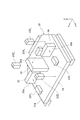
図2に示されるように、ティーチングユニット20は、複数の距離センサ23X1,23Y1,23Y2,23Z1,23Z2,23Z3を更に備えている。各距離センサ23X1,23Y1,23Y2,23Z1,23Z2,23Z3は、レーザ式の距離センサであり、本体部21内に取り付けられている。距離センサ23X1は、X軸方向に沿って本体部21の内方に向かってレーザ光を出射することで、対象物との距離を測定する。距離センサ23Y1,23Y2は、Y軸方向に沿って本体部21の内方に向かってレーザ光を出射することで、対象物との距離を測定する。距離センサ23Z1,23Z2,23Z3は、Z軸方向に沿って下方に向かってレーザ光を出射することで、対象物との距離を測定する。なお、図2では、本体部21及び制御部22の図示が省略されている。
ターゲットユニット30は、ベースプレート31と、複数のターゲットプレート(ターゲット)32,33,34と、を備えている。ベースプレート31は、ロードポート3に位置決めされた状態でロードポート3に取り付けられている。ベースプレート31において距離センサ23Z1,23Z2,23Z3と対向する表面31aは、Z軸方向に垂直な面であり、ロードポート3の基準面(例えば、被搬送物が載置されるロードポート3の載置面)に平行となっている。
各ターゲットプレート32,33,34は、ベースプレート31の所定位置に固定されている。ターゲットプレート32において距離センサ23X1と対向する表面32aは、X軸方向に垂直な面であり、ロードポート3の基準位置(ロードポート3の載置面の中心位置)と所定の位置関係を有している。ターゲットプレート33において距離センサ23Y1と対向する表面33a、及びターゲットプレート34において距離センサ23Y2と対向する表面34aは、Y軸方向に垂直な面であり、ロードポート3の基準位置と所定の位置関係を有している。
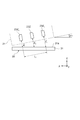
以上により、ティーチングユニット20の制御部22は、距離センサ23X1による測定距離X1、距離センサ23Y1による測定距離Y1、距離センサ23Y2による測定距離Y2、距離センサ23Z1による測定距離Z1、距離センサ23Z2による測定距離Z2及び距離センサ23Z3による測定距離Z3を取得することができる。そして、制御部22は、取得した複数の測定距離X1,Y1,Y2,Z1,Z2,Z3に基づいて、ロードポート3の基準位置を原点とした場合の保持部15の実位置(X座標,Y座標,Z座標)、並びに、角度θ、角度αx及び角度αyを算出することができる。
ここで、角度θは、図3に示されるように、ターゲットユニット30に対してティーチングユニット20がZ軸回りに回転している回転角度(すなわち、ロードポート3に対して保持部15がZ軸回りに回転している回転角度)である。距離センサ23Y1と距離センサ23Y2との距離をL1とすると、角度θは、θ=tan-1[(Y1-Y2)/L1]と表される。なお、図3では、距離センサ23X1,23Z1,23Z2,23Z3等の図示が省略されている。
また、角度αxは、図4に示されるように、ターゲットユニット30のベースプレート31の表面31aに対してティーチングユニット20がY軸回りに傾いている傾斜角度(すなわち、ロードポート3の基準面に対して保持部15がY軸回りに傾いている傾斜角度)である。距離センサ23Z1と距離センサ23Z3との距離をL2とすると、角度αxは、αx=tan-1[(Z3-Z1)/L2]と表される。なお、図4では、距離センサ23X1,23Y1,23Y2及びターゲットプレート32,33,34等の図示が省略されている。
また、角度αyは、図5に示されるように、ターゲットユニット30のベースプレート31の表面31aに対してティーチングユニット20がX軸回りに傾いている傾斜角度(すなわち、ロードポート3の基準面に対して保持部15がX軸回りに傾いている傾斜角度)である。距離センサ23Z1による測定距離Z1と距離センサ23Z3による測定距離Z3との平均値(すなわち、(Z1+Z3)/2)をZ13とし、距離センサ23Z1と距離センサ23Z3とを結ぶ直線と距離センサ23Z2との距離をL3とすると、角度αyは、αy=tan-1[(Z2-Z13)/L3]と表される。なお、図5では、距離センサ23X1,23Y1,23Y2及びターゲットプレート32,33,34等の図示が省略されている。
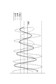
更に、天井搬送システム1では、制御部22によって次のような処理が行われる。すなわち、制御部22は、X軸方向、Y軸方向及びZ軸回りの回転方向のそれぞれの座標成分に測定値を変換し、変換した測定値のそれぞれに基づいて、保持部15のX座標及びY座標並びにZ軸回りの保持部15の角度θを検出する。これにより、ロードポート3の上方においてティーチングユニット20が揺れていたとしても、図6に示されるように、X座標、Y座標、角度θの時間的変化が規則的になるため、例えば、それぞれの振幅の中心値を求めることで、保持部15のX座標、Y座標、角度θを正確に求めることができる。制御部22が、X軸方向、Y軸方向及びZ軸回りの回転方向のそれぞれの座標成分に測定値を変換しないと、互いに周期が異なることから、図7に示されるように、測定距離X1,Y1,Y2の時間的変化が不規則になり、保持部15のX座標、Y座標、角度θを正確に求めることが困難になる。
以上、説明したように、ティーチングユニット20では、距離センサ23X1,23Y1,23Y2及び制御部22が、ロードポート3の上方においてロードポート3から離間した状態で、ロードポート3の基準位置に対する天井走行車10の位置(本実施形態では、ロードポート3の基準位置を原点とした場合の保持部15の実位置)を検出する位置検出部(すなわち、位置検出工程を実施する位置検出部)として機能する。更に、距離センサ23Z1,23Z2,23Z3及び制御部22が、ロードポート3の上方においてロードポート3から離間した状態で、ロードポート3の基準面に対する距離センサ23X1,23Y1,23Y2の傾き(換言すれば、天井走行車10の傾き(本実施形態では、ロードポート3の基準面に対する保持部15の傾き))を検出する傾き検出部(すなわち、傾き検出工程を実施する傾き検出部)として機能する。このように、ティーチングユニット20では、ロードポート3の基準面に対する距離センサ23X1,23Y1,23Y2の傾きが距離センサ23Z1,23Z2,23Z3によって検出されるため、ロードポート3の基準面に対して距離センサ23X1,23Y1,23Y2が傾いていたとしても、検出された距離センサ23X1,23Y1,23Y2の傾きに基づいて、ロードポート3の基準位置に対する保持部15の実位置を正確に求めることができる。このように、ティーチングユニット20(及びティーチングユニット20によって実施されるティーチング方法)によれば、ロードポート3の基準面に対する傾きによらず、ロードポート3の基準位置に対する保持部15の実位置を正確に求めることができる。
また、ティーチングユニット20では、上述した位置検出部として距離センサ23X1,23Y1,23Y2を用いることで、ロードポート3の基準位置に対する保持部15の実位置を簡単な構成で検出することができる。
また、ティーチングユニット20では、上述した位置検出部が、保持部15の実位置として、保持部15のX座標(第一方向における保持部15の第一位置)及び保持部15のY座標(第二方向における保持部15の第二位置)を検出すると共に、Z軸回りの回転方向における保持部15の角度θ(保持部15の回転角度)を検出する。これにより、保持部15のX座標、Y座標、角度θを正確に求めることができる。
また、ティーチングユニット20では、制御部22が、X軸方向、Y軸方向及びZ軸回りの回転方向のそれぞれの座標成分に測定値を変換し、変換した測定値のそれぞれに基づいて、保持部15のX座標及びY座標並びにZ軸回りの保持部15の角度θを検出する。これにより、ロードポート3の上方においてティーチングユニット20が揺れていたとしても、保持部15のX座標、Y座標、角度θを正確に求めることができる。
以上、本発明の一実施形態について説明したが、本発明は、上記実施形態に限定されるものではない。例えば、上記実施形態のティーチングユニット20は、ティーチングの実施時に天井走行車10に保持されたが、本発明のティーチングユニットは、天井走行車に組み込まれていてもよい。また、上記実施形態では、位置検出部として、距離センサ23X1,23Y1,23Y2が用いられたが、移載部の上方から、移載部の所定部を含む画像を取得する撮像装置が用いられてもよい。
また、本発明のティーチングユニットは、天井走行車及び移載部のうちの一方に搭載可能である。その場合、ターゲットは、天井走行車及び移載部のうちの他方に搭載される。一例として、ティーチングユニット20がロードポート3に搭載される場合、ターゲットユニット30は、天井走行車10に搭載される。そして、距離センサ23X1,23Y1,23Y2は、天井走行車10から離間した状態で、ロードポート3の基準位置に対する天井走行車10の位置を検出し(すなわち、位置検出工程を実施し)、距離センサ23Z1,23Z2,23Z3は、天井走行車10から離間した状態で、ロードポート3の基準面に対する距離センサ23X1,23Y1,23Y2の傾きを検出する(すなわち、傾き検出工程を実施する)。
本発明によれば、移載部の基準面に対する傾きによらず、移載部の基準位置に対する天井走行車の位置を正確に求めることができるティーチングユニット及びティーチング方法を提供することが可能になる。
3…ロードポート(移載部)、10…天井走行車、20…ティーチングユニット、22…制御部、23X1,23Y1,23Y2,23Z1,23Z2,23Z3…距離センサ。
Claims (6)
- 天井走行車、及び前記天井走行車によって被搬送物の移載が行われる移載部のうちの一方に搭載されるティーチングユニットであって、
前記天井走行車及び前記移載部のうちの他方から離間した状態で、前記移載部の基準位置に対する前記天井走行車の位置を検出する位置検出部と、
前記天井走行車及び前記移載部のうちの前記他方から離間した状態で、前記移載部の基準面に対する前記天井走行車の傾きを検出する傾き検出部と、を備えるティーチングユニット。 - 前記天井走行車及び前記移載部のうちの前記一方が前記天井走行車であり、前記天井走行車及び前記移載部のうちの前記他方が前記移載部である場合には、
前記位置検出部は、前記移載部の上方において、前記基準位置に対する前記位置を検出し、
前記傾き検出部は、前記移載部の上方において、前記基準面に対する前記傾きを検出する、請求項1記載のティーチングユニット。 - 前記位置検出部は、前記基準位置と所定の位置関係を有するターゲットとの距離を測定する距離センサを含む、請求項1又は2記載のティーチングユニット。
- 前記位置検出部は、前記位置として、前記天井走行車の走行方向に平行な第一方向における前記天井走行車の第一位置、及び前記基準面に平行且つ前記走行方向に垂直な第二方向における前記天井走行車の第二位置を検出すると共に、前記基準面に平行な面内での回転方向における前記天井走行車の回転角度を検出する、請求項1~3のいずれか一項記載のティーチングユニット。
- 前記位置検出部は、前記第一方向、前記第二方向及び前記回転方向のそれぞれの座標成分に測定値を変換し、変換した前記測定値のそれぞれに基づいて、前記第一位置、前記第二位置及び前記回転角度を検出する、請求項4記載のティーチングユニット。
- 天井走行車、及び前記天井走行車によって被搬送物の移載が行われる移載部のうちの一方に搭載されるティーチングユニットによって実施されるティーチング方法であって、
前記天井走行車及び前記移載部のうちの他方から離間した状態で、前記移載部の基準位置に対する前記天井走行車の位置を検出する位置検出工程と、
前記天井走行車及び前記移載部のうちの前記他方から離間した状態で、前記移載部の基準面に対する前記天井走行車の傾きを検出する傾き検出工程と、を備えるティーチング方法。
Priority Applications (1)
| Application Number | Priority Date | Filing Date | Title |
|---|---|---|---|
| JP2016515900A JP6146537B2 (ja) | 2014-05-01 | 2015-03-18 | ティーチングユニット及びティーチング方法 |
Applications Claiming Priority (2)
| Application Number | Priority Date | Filing Date | Title |
|---|---|---|---|
| JP2014-094582 | 2014-05-01 | ||
| JP2014094582 | 2014-05-01 |
Publications (1)
| Publication Number | Publication Date |
|---|---|
| WO2015166738A1 true WO2015166738A1 (ja) | 2015-11-05 |
Family
ID=54358478
Family Applications (1)
| Application Number | Title | Priority Date | Filing Date |
|---|---|---|---|
| PCT/JP2015/058095 Ceased WO2015166738A1 (ja) | 2014-05-01 | 2015-03-18 | ティーチングユニット及びティーチング方法 |
Country Status (3)
| Country | Link |
|---|---|
| JP (1) | JP6146537B2 (ja) |
| TW (1) | TW201546588A (ja) |
| WO (1) | WO2015166738A1 (ja) |
Cited By (6)
| Publication number | Priority date | Publication date | Assignee | Title |
|---|---|---|---|---|
| KR20170065734A (ko) * | 2015-12-03 | 2017-06-14 | 에스케이하이닉스 주식회사 | 촬상 유닛을 포함하는 반도체 제조 장치 |
| CN108202335A (zh) * | 2016-12-16 | 2018-06-26 | 发那科株式会社 | 示教器及具有该示教器的机器人系统 |
| JPWO2017199593A1 (ja) * | 2016-05-20 | 2019-03-14 | 村田機械株式会社 | 搬送車及び搬送方法 |
| CN110326097A (zh) * | 2017-03-28 | 2019-10-11 | 村田机械株式会社 | 桥式输送车 |
| JP2024176925A (ja) * | 2023-06-09 | 2024-12-19 | 株式会社ダイフク | 検査装置 |
| WO2026063052A1 (ja) * | 2024-09-20 | 2026-03-26 | 村田機械株式会社 | 搬送車システム |
Families Citing this family (4)
| Publication number | Priority date | Publication date | Assignee | Title |
|---|---|---|---|---|
| CN110235235B (zh) * | 2017-04-06 | 2023-01-06 | 村田机械株式会社 | 桥式输送车系统以及示教单元 |
| JP7192732B2 (ja) | 2019-09-27 | 2022-12-20 | 株式会社ダイフク | 位置関係検出システム |
| KR102579642B1 (ko) * | 2021-11-24 | 2023-09-15 | 세메스 주식회사 | Oht 비히클 및 이의 동작 제어 방법 |
| JP2025064718A (ja) | 2023-10-06 | 2025-04-17 | 株式会社ダイフク | 位置関係検出システム |
Citations (10)
| Publication number | Priority date | Publication date | Assignee | Title |
|---|---|---|---|---|
| JPH06131032A (ja) * | 1992-04-14 | 1994-05-13 | Hitachi Ltd | ロボット装置およびロボット装置のティ−チング方法。 |
| JPH11349280A (ja) * | 1998-06-05 | 1999-12-21 | Shinko Electric Co Ltd | 懸垂式搬送装置 |
| JP2001071288A (ja) * | 1999-09-06 | 2001-03-21 | Murata Mach Ltd | 搬送システムのティーチング方法とその装置 |
| JP2005170544A (ja) * | 2003-12-08 | 2005-06-30 | Asyst Shinko Inc | 位置教示装置及びそれを備えた搬送システム |
| JP2006318021A (ja) * | 2005-05-10 | 2006-11-24 | Murata Mach Ltd | 天井走行車システム用のティーチングユニット及び受け渡しデータの取得方法 |
| JP4122521B2 (ja) * | 2005-01-17 | 2008-07-23 | 村田機械株式会社 | 天井走行車システム |
| JP2010087358A (ja) * | 2008-10-01 | 2010-04-15 | Muratec Automation Co Ltd | 搬送システム及びズレ検出用治具 |
| WO2011013338A1 (ja) * | 2009-07-29 | 2011-02-03 | ムラテックオートメーション株式会社 | 搬送システム及びその設定方法 |
| WO2014115472A1 (ja) * | 2013-01-28 | 2014-07-31 | 村田機械株式会社 | 移載装置及び移載方法 |
| JP2015086019A (ja) * | 2013-10-28 | 2015-05-07 | 村田機械株式会社 | 教示システム |
Family Cites Families (2)
| Publication number | Priority date | Publication date | Assignee | Title |
|---|---|---|---|---|
| JP2011071288A (ja) * | 2009-09-25 | 2011-04-07 | Disco Abrasive Syst Ltd | ウエーハの加工方法 |
| TWI415785B (zh) * | 2011-01-12 | 2013-11-21 | Inotera Memories Inc | 天車輸送系統與其操作方法 |
-
2015
- 2015-03-18 WO PCT/JP2015/058095 patent/WO2015166738A1/ja not_active Ceased
- 2015-03-18 JP JP2016515900A patent/JP6146537B2/ja active Active
- 2015-04-22 TW TW104112855A patent/TW201546588A/zh unknown
Patent Citations (10)
| Publication number | Priority date | Publication date | Assignee | Title |
|---|---|---|---|---|
| JPH06131032A (ja) * | 1992-04-14 | 1994-05-13 | Hitachi Ltd | ロボット装置およびロボット装置のティ−チング方法。 |
| JPH11349280A (ja) * | 1998-06-05 | 1999-12-21 | Shinko Electric Co Ltd | 懸垂式搬送装置 |
| JP2001071288A (ja) * | 1999-09-06 | 2001-03-21 | Murata Mach Ltd | 搬送システムのティーチング方法とその装置 |
| JP2005170544A (ja) * | 2003-12-08 | 2005-06-30 | Asyst Shinko Inc | 位置教示装置及びそれを備えた搬送システム |
| JP4122521B2 (ja) * | 2005-01-17 | 2008-07-23 | 村田機械株式会社 | 天井走行車システム |
| JP2006318021A (ja) * | 2005-05-10 | 2006-11-24 | Murata Mach Ltd | 天井走行車システム用のティーチングユニット及び受け渡しデータの取得方法 |
| JP2010087358A (ja) * | 2008-10-01 | 2010-04-15 | Muratec Automation Co Ltd | 搬送システム及びズレ検出用治具 |
| WO2011013338A1 (ja) * | 2009-07-29 | 2011-02-03 | ムラテックオートメーション株式会社 | 搬送システム及びその設定方法 |
| WO2014115472A1 (ja) * | 2013-01-28 | 2014-07-31 | 村田機械株式会社 | 移載装置及び移載方法 |
| JP2015086019A (ja) * | 2013-10-28 | 2015-05-07 | 村田機械株式会社 | 教示システム |
Cited By (11)
| Publication number | Priority date | Publication date | Assignee | Title |
|---|---|---|---|---|
| KR20170065734A (ko) * | 2015-12-03 | 2017-06-14 | 에스케이하이닉스 주식회사 | 촬상 유닛을 포함하는 반도체 제조 장치 |
| KR102570567B1 (ko) * | 2015-12-03 | 2023-08-29 | 에스케이하이닉스 주식회사 | 촬상 유닛을 포함하는 반도체 제조 장치 |
| JPWO2017199593A1 (ja) * | 2016-05-20 | 2019-03-14 | 村田機械株式会社 | 搬送車及び搬送方法 |
| CN108202335A (zh) * | 2016-12-16 | 2018-06-26 | 发那科株式会社 | 示教器及具有该示教器的机器人系统 |
| US10513039B2 (en) | 2016-12-16 | 2019-12-24 | Fanuc Corporation | Teach pendant and robot system provided with the same |
| CN108202335B (zh) * | 2016-12-16 | 2020-01-10 | 发那科株式会社 | 示教器及具有该示教器的机器人系统 |
| CN110326097A (zh) * | 2017-03-28 | 2019-10-11 | 村田机械株式会社 | 桥式输送车 |
| CN110326097B (zh) * | 2017-03-28 | 2023-03-03 | 村田机械株式会社 | 桥式输送车 |
| JP2024176925A (ja) * | 2023-06-09 | 2024-12-19 | 株式会社ダイフク | 検査装置 |
| JP7819677B2 (ja) | 2023-06-09 | 2026-02-25 | 株式会社ダイフク | 検査装置 |
| WO2026063052A1 (ja) * | 2024-09-20 | 2026-03-26 | 村田機械株式会社 | 搬送車システム |
Also Published As
| Publication number | Publication date |
|---|---|
| TW201546588A (zh) | 2015-12-16 |
| JPWO2015166738A1 (ja) | 2017-04-20 |
| JP6146537B2 (ja) | 2017-06-14 |
Similar Documents
| Publication | Publication Date | Title |
|---|---|---|
| JP6146537B2 (ja) | ティーチングユニット及びティーチング方法 | |
| JP6119699B2 (ja) | 移載位置決定方法 | |
| JP6710622B2 (ja) | 搬送装置および搬送方法 | |
| TWI382491B (zh) | Position control fixture | |
| US9026244B1 (en) | Presence sensing and position correction for wafer on a carrier ring | |
| US10042356B2 (en) | Substrate processing apparatus, method for correcting positional displacement, and storage medium | |
| CN107771024B (zh) | 用于转移电子装置的设备和方法 | |
| US9908236B2 (en) | Transfer system and transfer method | |
| KR101015192B1 (ko) | 위치 검출용 지그 | |
| TWI404077B (zh) | 晶圓輸送系統中晶圓對位的校正系統及方法與晶圓盒 | |
| CN105590888A (zh) | 晶片传送机器人及其控制方法和制造半导体装置的方法 | |
| WO2020116510A1 (ja) | 基板搬送装置及びその運転方法 | |
| CN105514010B (zh) | 一种硅片安全运输方法 | |
| CN110364461B (zh) | 晶圆状态检测设备、方法及晶圆装卸载腔室 | |
| JP7614764B2 (ja) | ロボット及び基板形状異常検査方法 | |
| JP7610939B2 (ja) | ロボット及びハンド部姿勢調整方法 | |
| CN105097591B (zh) | 一种硅片分布状态光电图像组合扫描方法及装置 | |
| CN104752295B (zh) | 位置监测装置、等离子体加工设备及工件的装卸方法 | |
| CN114613711A (zh) | 一种晶圆调节装置、调节方法及半导体制造设备 | |
| KR20190011979A (ko) | 호이스트 모듈의 티칭 방법 및 이를 수행하기 위한 장치 | |
| WO2015145864A1 (ja) | 位置ずれ検出方法、位置ずれ検出装置、描画装置および基板検査装置 | |
| JP7614763B2 (ja) | ロボット及び基板姿勢検査方法 | |
| EP3970926A1 (en) | Controller | |
| CN114814869A (zh) | 一种晶圆检测装置及方法 | |
| JP7192682B2 (ja) | 検査システム |
Legal Events
| Date | Code | Title | Description |
|---|---|---|---|
| 121 | Ep: the epo has been informed by wipo that ep was designated in this application |
Ref document number: 15785732 Country of ref document: EP Kind code of ref document: A1 |
|
| DPE1 | Request for preliminary examination filed after expiration of 19th month from priority date (pct application filed from 20040101) | ||
| ENP | Entry into the national phase |
Ref document number: 2016515900 Country of ref document: JP Kind code of ref document: A |
|
| NENP | Non-entry into the national phase |
Ref country code: DE |
|
| 122 | Ep: pct application non-entry in european phase |
Ref document number: 15785732 Country of ref document: EP Kind code of ref document: A1 |