WO2015159967A1 - タイヤプリンター - Google Patents
タイヤプリンター Download PDFInfo
- Publication number
- WO2015159967A1 WO2015159967A1 PCT/JP2015/061795 JP2015061795W WO2015159967A1 WO 2015159967 A1 WO2015159967 A1 WO 2015159967A1 JP 2015061795 W JP2015061795 W JP 2015061795W WO 2015159967 A1 WO2015159967 A1 WO 2015159967A1
- Authority
- WO
- WIPO (PCT)
- Prior art keywords
- tire
- printer
- portions
- wheel
- pair
- Prior art date
- Legal status (The legal status is an assumption and is not a legal conclusion. Google has not performed a legal analysis and makes no representation as to the accuracy of the status listed.)
- Ceased
Links
Images










Classifications
-
- B—PERFORMING OPERATIONS; TRANSPORTING
- B29—WORKING OF PLASTICS; WORKING OF SUBSTANCES IN A PLASTIC STATE IN GENERAL
- B29D—PRODUCING PARTICULAR ARTICLES FROM PLASTICS OR FROM SUBSTANCES IN A PLASTIC STATE
- B29D30/00—Producing pneumatic or solid tyres or parts thereof
- B29D30/06—Pneumatic tyres or parts thereof (e.g. produced by casting, moulding, compression moulding, injection moulding, centrifugal casting)
- B29D30/72—Side-walls
-
- B—PERFORMING OPERATIONS; TRANSPORTING
- B41—PRINTING; LINING MACHINES; TYPEWRITERS; STAMPS
- B41J—TYPEWRITERS; SELECTIVE PRINTING MECHANISMS, i.e. MECHANISMS PRINTING OTHERWISE THAN FROM A FORME; CORRECTION OF TYPOGRAPHICAL ERRORS
- B41J3/00—Typewriters or selective printing or marking mechanisms characterised by the purpose for which they are constructed
- B41J3/407—Typewriters or selective printing or marking mechanisms characterised by the purpose for which they are constructed for marking on special material
- B41J3/4073—Printing on three-dimensional objects not being in sheet or web form, e.g. spherical or cubic objects
-
- B—PERFORMING OPERATIONS; TRANSPORTING
- B29—WORKING OF PLASTICS; WORKING OF SUBSTANCES IN A PLASTIC STATE IN GENERAL
- B29D—PRODUCING PARTICULAR ARTICLES FROM PLASTICS OR FROM SUBSTANCES IN A PLASTIC STATE
- B29D30/00—Producing pneumatic or solid tyres or parts thereof
- B29D30/06—Pneumatic tyres or parts thereof (e.g. produced by casting, moulding, compression moulding, injection moulding, centrifugal casting)
- B29D30/72—Side-walls
- B29D2030/728—Decorating or marking the sidewalls after tyre vulcanization
Definitions
- the present invention relates to a tire printer that performs printing on a tire.
- a wheel support portion that supports a wheel attached to the tire, a tire rotation portion that rotates the wheel support portion that supports the tire via the wheel in the circumferential direction of the tire, and a wheel support that supports the wheel via the wheel
- a tire printer including an inkjet head that performs printing on a side surface portion of a tire supported by a section (see, for example, Patent Document 1).
- a tire placement portion in which a pair of side surface portions of a tire are placed vertically in the vertical direction, and a tire rotation portion that rotates the tire placement portion on which the tire is placed in the circumferential direction of the tire And an inkjet head that performs printing on the upper side surface portion of the pair of side surface portions of the tire mounted on the tire mounting portion (see, for example, Patent Document 2) .)
- the tire placement portion of the tire printer the tire is placed by supporting the upper side surface portion from the lower side of the pair of side surface portions of the tire.
- Patent Document 1 since the tire printer described in Patent Document 1 performs printing only on a tire to which a wheel is attached, there is a problem in that printing cannot be performed on a tire to which a wheel is not attached.
- the tire printer described in Patent Document 2 can execute printing on a tire to which no wheel is attached.
- the pair of side surface portions of the tire are arranged vertically in the vertical direction, and the upper side surface portion of the pair of side surface portions of the tire is supported from the lower side. Therefore, the upper side surface portion of the pair of side surface portions of the tire, that is, the portion to be printed by the inkjet head may be deformed by the weight of the tire. Therefore, the tire printer described in Patent Document 2 has a problem that it is difficult to perform high-precision printing on the tire.
- an object of the present invention is to provide a tire printer capable of executing printing with higher accuracy than a conventional tire printer on a tire to which no wheel is attached.
- the tire printer of the present invention is a tire printer that performs printing on a side surface of a tire, and a tire placement unit that places the tire in a state where a pair of side surface portions of the tire are vertically oriented in a vertical direction. Printing on the upper side surface portion of the pair of side surface portions of the tire mounted on the tire mounting portion, and a tire rotating portion that rotates the tire mounting portion in the circumferential direction of the tire.
- the tire mounting portion supports a lower side surface portion of the pair of side surface portions from the lower side in the vertical direction.
- the pair of side surface portions of the tire are vertically arranged in the vertical direction, and the lower side surface portion of the pair of side surface portions of the tire is supported from below by the tire placement portion. The Therefore, it is possible to suppress the upper side surface portion of the pair of side surface portions of the tire, that is, the portion to be printed by the inkjet head, from being deformed by the tire's own weight as compared with the conventional tire printer. Therefore, the tire printer of the present invention can perform printing with higher accuracy than the conventional tire printer on a tire to which no wheel is attached.
- the tire placement portion positions the tire in a direction orthogonal to the tire rotation axis by the tire rotation portion and a plurality of tire support portions that support the lower side surface portion from the lower side.
- a tire positioning portion, and the plurality of tire support portions may each support the tire positioning portion.
- the tire printer of the present invention has a tire support portion in a direction perpendicular to the tire rotation axis by the tire rotation portion and the tire positioning compared to a configuration in which the tire positioning portion is not supported by the tire support portion.
- the positional accuracy with the part can be improved. Therefore, the positional accuracy of the plurality of tire support portions and the tire positioned by the tire positioning portion can be improved in the direction perpendicular to the tire rotation axis by the tire rotation portion. Therefore, the tire printer of the present invention can stably support the tire by the plurality of tire support portions. Therefore, the tire printer of the present invention can execute high-precision printing on a tire to which no wheel is attached.
- the tire positioning unit may position the tire in a direction orthogonal to the rotation axis by contacting the inner peripheral portion of the tire.
- the tire printer according to the present invention has a distance between the tire rotation axis and the tire positioning portion by the tire rotating portion, as compared with the configuration in which the tire positioning portion contacts the outer peripheral portion of the tire to position the tire. Is short. Therefore, in the direction orthogonal to the tire rotation axis by the tire rotation unit, the amount of positional deviation between the tire central axis positioned by the plurality of tire positioning units and the tire rotation axis by the tire rotation unit is reduced. Can do. Therefore, the tire printer of the present invention can perform high-precision printing on the tire by the inkjet head by rotating the tire to which the wheel is not attached by the tire rotating unit.
- the tire placement portion includes three tire support portions as a plurality of tire support portions, the tire support portions are arranged long in the radial direction of the tire, and the three tire support portions are: You may arrange
- the lower side surface portion of the pair of side surface portions of the tire is arranged at equal intervals on the same circumference around the rotation axis of the tire by the tire rotation portion. It is supported by the three tire support portions. Therefore, the tire can be stably supported as compared with the configuration in which the entire lower side surface portion of the pair of side surface portions is supported by the plane. Therefore, the tire printer of the present invention can execute high-precision printing on a tire to which no wheel is attached.
- the tire placement unit may include a link mechanism that simultaneously moves a tire positioning unit supported by each of the three tire support units in the radial direction.
- the tire printer of the present invention when the tire positioning portion is moved in the tire radial direction, the tire printer of the present invention has three tire positioning portions on the same circumference around the tire rotation axis by the tire rotating portion. Are maintained at equal intervals by the link mechanism. Therefore, compared with a configuration in which each of the three tire positioning portions is independently moved in the radial direction of the tire, the position where the tire is placed in the tire placement portion can be determined with high accuracy. Therefore, the tire printer of the present invention can execute high-precision printing on a tire to which no wheel is attached.
- the tire placement portion includes three tire support portions that support the lower side surface portion from the lower side in the vertical direction. You may arrange
- the tire printer of the present invention has the lower side surface portion of the pair of side surface portions of the tire arranged at equal intervals on the same circumference around the rotation axis of the tire by the tire rotation portion. It is supported by the three tire support portions. Therefore, the tire can be stably supported as compared with the configuration in which the entire lower side surface portion of the pair of side surface portions is supported by the plane. Therefore, the tire printer of the present invention can execute high-precision printing on a tire to which no wheel is attached.
- the tire placement portion includes three tire positioning portions that position the tire in a direction orthogonal to the tire rotation axis by the tire rotation portion, and the three tire positioning portions centered on the rotation axis. And a link mechanism that simultaneously moves the three tire positioning portions in the radial direction of the tire at equal intervals on the same circumference.
- the tire printer of the present invention when the tire positioning unit is moved in the radial direction of the tire, the tire printer of the present invention has the same three tire positioning units centered on the rotation axis of the tire by the tire rotating unit by the link mechanism. Maintained at regular intervals on the circumference. Therefore, compared with a configuration in which each of the three tire positioning portions is independently moved in the radial direction of the tire, the position where the tire is placed in the tire placement portion can be determined with high accuracy. Therefore, the tire printer of the present invention can execute high-precision printing on a tire to which no wheel is attached.
- the tire printer of the present invention includes a wheel support portion that supports a wheel attached to the tire with a pair of side surface portions of the tire arranged vertically in the vertical direction.
- the tire rotation unit rotates the wheel support unit in order to rotate the tire supported by the wheel support unit via the wheel in the circumferential direction of the tire.
- the inkjet head may perform printing on the upper side of the upper side surface portion when the tire is supported by the wheel support portion via the wheel.
- the tire printer of the present invention can execute printing on a tire to which a wheel is attached by attaching the wheel support portion to the tire rotating portion. Therefore, printing can be executed not only on a tire not attached with a wheel but also on a tire attached with a wheel.
- the tire printer of the present invention can perform printing on a tire without a wheel attached with higher accuracy than a conventional tire printer.
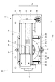
- FIG. 1 is an external perspective view of a tire printer when a tire printer according to an embodiment of the present invention in a state where a tire to which a wheel is attached is installed is observed from the upper left toward the front.
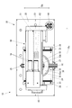
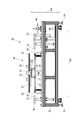
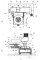
- FIG. 2 is an external perspective view of the tire printer when the tire printer in the state shown in FIG. 1 is observed from the upper right side toward the front. It is a front view of the tire printer in the state shown in FIG. It is a top view of the tire printer in the state shown in FIG. It is side surface sectional drawing of the tire support apparatus in the state shown in FIG. It is a front view of the tire printer shown in FIG. 1 in the state in which the tire to which the wheel is not attached is installed.
- FIG. 10 is a partial front view of the tire support device shown in FIG. 9.
- FIG. 10 is a plan view of a part of the tire support device shown in FIG. 9.
- It is a block diagram of the tire printer shown in FIG. It is the top view and side view of a tire printer which are shown in FIG.
- It is a bottom view of the tire mounting part shown in Drawing 1 in the state where three stoppers approach each other.
- FIG 16 is a bottom view of the tire mounting part shown in Drawing 16 in the state where three stoppers are separated from each other.
- FIG. 1 is an external perspective view of the tire printer 10 when the tire printer 10 according to the present embodiment in a state where a tire 91 to which a wheel 92 is attached is installed is observed from the upper left toward the front. is there.
- FIG. 2 is an external perspective view of the tire printer 10 when the tire printer 10 in the state shown in FIG. 1 is observed from the upper right toward the front.
- FIG. 3 is a front view of the tire printer 10 in the state shown in FIG.
- FIG. 4 is a plan view of the tire printer 10 in the state shown in FIG.
- the tire printer 10 includes a tire support device 20 that supports a tire such as a tire 91, and an ink jet printer 50 that is supported by the tire support device 20.
- the tire support device 20 is arranged on the upper side of the leg portion 21 in the vertical direction indicated by the arrow 10a, that is, in the vertical direction indicated by the arrow 10a, and is supported by the leg portion 21. And a rectangular parallelepiped frame 22.
- FIG. 5 is a side sectional view of the tire support device 20 in the state shown in FIG.
- the tire support device 20 is supported by the frame body 22 on the upper side of the frame body 22, and includes a vertical direction indicated by an arrow 10a and a front-back direction indicated by an arrow 10b orthogonal to the vertical direction.
- a stop member 26 for restricting the movement of the slide plate 24 in the front-rear direction and a front end of the slide plate 24 are attached.
- a handle 27 that is gripped by the user and a pin 28 that is inserted into the slide rail 23 and the slide plate 24 and fixes the slide plate 24 so that the slide plate 24 does not move in the front-rear direction with respect to the frame body 22 are provided. .
- the pair of slide rails 23 is provided long in the front-rear direction indicated by the arrow 10b, and supports the slide plate 24 so as to be movable in the front-rear direction with respect to the frame body 22.
- the tire support device 20 includes a DD (Direct Drive) motor 29 supported by a slide plate 24, and a tire placement portion 30 that is rotatably supported by the DD motor 29 and on which a tire is placed. Yes.
- DD Direct Drive
- FIG. 6 is a front view of the tire printer 10 in a state where a tire 93 to which no wheel is attached is installed.
- FIG. 7 is a plan view of the tire printer 10 in the state shown in FIG.
- FIG. 8 is a side sectional view of the tire support device 20 in the state shown in FIG.
- FIG. 9 is a perspective view of a part of the tire support device 20.
- FIG. 10 is a front view of a part of the tire support device 20.
- FIG. 11 is a plan view of a part of the tire support device 20.
- the tire support device 20 has a shaft 41 (see FIG. 3) described later removed from the tire placement portion 30.
- the tire placement unit 30 is supported by a disc 31 rotatably supported by the DD motor 29, three rails 32 fixed on the disc 31, and one each of the three rails 32. And three stoppers 33 for fixing the tire 93.
- the tire placement section 30 places the tire 93 up and down in the up-down direction indicated by the arrows 10a of the pair of side surface portions 93a of the tire 93.
- the tire placement unit 30 places the tire 93 by supporting the lower side surface portion 93 a of the pair of side surface portions 93 a of the tire 93 from the lower side in the vertical direction.
- the disk 31 is provided with a shaft fixing hole 31a for fixing the shaft 41 at the center.
- the disc 31 is provided with three rails 32 at equal intervals on the same circumference centered on the rotation shaft 90a (see FIG. 8) of the tire 93 by the DD motor 29.
- the rail 32 constitutes a tire support portion that supports the lower side surface portion 93a of the pair of side surface portions 93a of the tire 93 from the lower side in the vertical direction.
- the rail 32 extends long in the radial direction indicated by the arrow 90b (see FIG. 11) of the tire 93, and supports the stopper 33 so as to be movable in the radial direction indicated by the arrow 90b.
- the three stoppers 33 are arranged at equal intervals around the rotation axis 90a of the tire 93.
- the stopper 33 fixes the tire 93 by contacting the inner peripheral portion 93b of the tire 93 in the radial direction indicated by the arrow 90b of the tire 93 in a direction away from the rotation shaft 90a of the tire 93 by the DD motor 29.
- the stopper 33 constitutes a tire positioning portion that positions the tire 93 in a direction orthogonal to the rotation shaft 90a.
- the stopper 33 is fixed to the rail 32 by a screw (not shown) inserted into a through hole 33a that opens to the top.
- the DD motor 29 rotates the tire placement unit 30 so that the tire 93 placed on the tire placement unit 30 rotates in the circumferential direction indicated by an arrow 90c (see FIG. 11) of the tire 93. .
- the DD motor 29 constitutes a tire rotating part.
- the tire support device 20 includes a shaft 41 that is detachably provided in the shaft fixing hole 31 a of the disk 31 of the tire placement portion 30, a nut 42 that is attached to the shaft 41, It has.
- the shaft 41 constitutes a wheel support portion that supports a wheel 92 attached to the tire 91.
- the nut 42 fastens the wheel 92 to the shaft 41 inserted into the wheel 92 of the tire 91.
- the shaft 41 is fixed to the disc 31. Accordingly, the tire 91 is fixed to the disc 31 via the shaft 41.
- the shaft 41 supports the tire 91 via a wheel 92 of the tire 91 in which a pair of side surface portions 91a are arranged vertically in the vertical direction indicated by the arrow 10a.
- the tire 91 is not placed on the tire placement portion 30.
- the DD motor 29 rotates the shaft 41 via the disc 31 and rotates the tire 91 supported by the shaft 41 via the wheel 92 in the circumferential direction indicated by the arrow 90 c of the tire 91.
- the tire support device 20 includes a pair of printer up / down mechanisms 43, a handle 44, and a transmission mechanism (not shown).
- the pair of printer up / down mechanisms 43 supports the inkjet printer 50.
- the pair of printer vertical mechanisms 43 are supported by the frame body 22 so as to be movable in the vertical direction indicated by the arrow 10a.
- the handle 44 is rotated by the user to move the printer vertical mechanism 43 in the vertical direction.
- the transmission mechanism moves the printer vertical mechanism 43 in the vertical direction as the handle 44 rotates.
- the pair of printer up-and-down mechanisms 43 are disposed to face each other in the left-right direction indicated by the arrow 10c with the pair of slide rails 23 interposed therebetween.
- the ink jet printer 50 is supported by the guide rail 51 extending in the left-right direction indicated by the arrow 10c and movably in the left-right direction indicated by the arrow 10c.
- a plurality of inkjet heads 53 that are mounted on the carriage 52 and eject ink droplets toward the tire 91, and a plurality of tanks 54 that supply ink to the inkjet heads 53.
- the inkjet head 53 performs printing on the surface of the upper side surface portion 91a of the pair of side surface portions 91a of the tire 91 supported by the shaft 41 via the wheel 92. Further, as shown in FIGS. 6 and 7, the inkjet head 53 performs printing on the upper side of the upper side surface portion 93 a of the pair of side surface portions 93 a of the tire 93 mounted on the tire mounting portion 30. .
- FIG. 12 is a block diagram of the tire printer 10.
- the tire printer 10 is an operation unit 61 that is an input device such as a button for inputting information by various operations, and a display device such as an LCD (Liquid Crystal Display) that displays various information.
- a display unit 62, a communication unit 63 that is a communication device that communicates with an external device such as a PC (Personal Computer), the DD motor 29 and the inkjet head 53, and the carriage 52 (see FIG. 1) described above are guided.
- a carriage drive device 64 for moving in the left-right direction indicated by an arrow 10c (see FIG. 1) along the rail 51 (see FIG. 1), and an EEPROM (Electrically Erasable Programmable Read On) that stores various data.
- y Memory memory 65 is a storage device such as, and a control unit 66 for controlling the entire tire printer 10.
- the controller 66 includes, for example, a CPU (Central Processing Unit), a ROM (Read Only Memory) that stores programs and various data in advance, and a RAM (Random Access Memory) used as a work area of the CPU. I have.
- the CPU sequentially reads and executes the programs stored in the ROM or the storage unit 65.
- FIG. 13A is a plan view of the tire printer 10 in a state where the slide plate 24 is pulled out.
- FIG. 13B is a side view of the tire printer 10 in the state shown in FIG.
- the user grasps the handle 27, moves the slide plate 24 forward in the front-rear direction indicated by the arrow 10b, and moves the slide plate 24 to the inkjet printer. Pull out from under 50 as shown in FIG.
- the user inserts the pin 28 into the slide rail 23 and the slide plate 24 and positions the slide plate 24.
- the user attaches the shaft 41 to the shaft fixing hole 31 a of the disc 31.
- FIG. 14A is a plan view of the tire printer 10 in a state where the tire 91 to which the wheel 92 is attached is supported and the slide plate 24 is pulled out.
- FIG. 14B is a side view of the tire printer 10 in the state shown in FIG.
- the user turns the handle 44 so that the tire 91 does not interfere with the inkjet printer 50, and the vertical position indicated by the arrow 10 a of the inkjet printer 50. Adjust.
- the user removes the pin 28 from the slide rail 23 and the slide plate 24, grasps the handle 27, and moves the slide plate 24 in the rearward direction in the front-rear direction indicated by the arrow 10b.
- the slide plate 24 is stored under the ink jet printer 50. The user inserts the pin 28 into the slide rail 23 and the slide plate 24 and positions the slide plate 24.
- the user adjusts the vertical position indicated by the arrow 10a of the inkjet printer 50 by turning the handle 44 so that the inkjet printer 50 can execute printing on the tire 91.
- the tire 91 is installed in the tire printer 10 as shown in FIGS.
- the user grasps the handle 27 and moves the slide plate 24 forward in the front-rear direction indicated by the arrow 10b.
- the slide plate 24 is pulled out from below the inkjet printer 50 as shown in FIG.
- the user inserts the pin 28 into the slide rail 23 and the slide plate 24 and positions the slide plate 24.
- the shaft 41 is attached to the shaft fixing hole 31 a of the disc 31, the user removes the shaft 41 from the shaft fixing hole 31 a of the disc 31.
- the user loosens the screw inserted into the through hole 33 a of the stopper 33 to release the fixing of the stopper 33 with respect to the rail 32, and thereby the three stoppers 33.
- the stopper 33 is moved along the rail 32 in the direction indicated by the arrow 90b so that they approach each other. That is, the user moves the stopper 33 on the rail 32 in the radial direction indicated by the arrow 90 b of the tire 93 in a direction approaching the rotation axis 90 a of the tire 93 by the DD motor 29.
- the user places the tire 93 on the three rails 32 so that the three stoppers 33 are surrounded by the inner peripheral portion 93 b of the tire 93.
- FIG. 15A is a plan view of the tire printer 10 in a state where the tire 93 to which no wheel is attached is supported and the slide plate 24 is pulled out.
- FIG. 15B is a side view of the tire printer 10 in the state shown in FIG.
- the user places the tire 93 on the three rails 32.
- the user moves the stopper 33 on the rail 32 in a direction away from the rotation axis 90 a of the tire 93 by the DD motor 29 in the radial direction indicated by the arrow 90 b of the tire 93, and moves the three stoppers 33 to the inner peripheral portion of the tire 93.
- 93b is contacted.
- the user fastens the stopper 33 to the rail 32 by tightening the screw inserted into the through hole 33 a of the stopper 33.
- the tire 93 is fixed to the tire placement portion 30 by the stopper 33.
- the user turns the handle 44 so that the tire 93 does not interfere with the inkjet printer 50, and the vertical position indicated by the arrow 10 a of the inkjet printer 50. Adjust.
- the user grasps the handle 27 and moves the slide plate 24 backward in the front-rear direction indicated by the arrow 10b.
- the slide plate 24 is stored under the ink jet printer 50. The user inserts the pin 28 into the slide rail 23 and the slide plate 24 and positions the slide plate 24.
- the user adjusts the vertical position indicated by the arrow 10a of the inkjet printer 50 by turning the handle 44 so that printing can be performed on the tire 93 by the inkjet printer 50.
- the tire 93 is installed in the tire printer 10 as shown in FIGS.
- control unit 66 of the tire printer 10 When the control unit 66 of the tire printer 10 receives print data transmitted from the outside via the communication unit 63, the control unit 66 controls the DD motor 29, the inkjet head 53, and the carriage drive device 64 based on the print data. Then, printing is performed on tires such as the tires 91 and 93 by the inkjet head 53.
- control unit 66 controls the carriage driving device 64 to move the carriage 52 in the left-right direction indicated by the arrow 10 c along the guide rail 51, thereby moving the inkjet head 53 mounted on the carriage 52. It is moved relative to the tire in the left-right direction indicated by arrow 10c. At this time, the control unit 66 executes printing in the left-right direction indicated by the arrow 10c by ejecting ink droplets toward the tire by the inkjet head 53. The control unit 66 changes the printing position of the inkjet head 53 with respect to the tire by controlling the DD motor 29 and rotating the tire every time printing in the left-right direction indicated by the arrow 10c is completed. And the control part 66 performs the printing in the left-right direction shown by the arrow 10c again in a new printing position.
- the pair of side surface portions 93a of the tire 93 is vertically moved in the vertical direction indicated by the arrow 10a, and the lower side surface portion 93a of the pair of side surface portions 93a of the tire 93 is vertically aligned. Therefore, the upper side surface portion 93a of the pair of side surface portions 93a of the tire 93, that is, the portion to be printed by the inkjet head 53 is prevented from being deformed by the weight of the tire 93 as compared with the conventional tire printer. be able to. Therefore, the tire printer 10 can perform printing with higher accuracy than the conventional tire printer on the tire 93 to which no wheel is attached.
- the tire printer 10 improves the positional accuracy between the rail 32 and the stopper 33 in the direction perpendicular to the rotation axis 90a of the tire 93 by the DD motor 29, as compared with the configuration in which the stopper 33 is not supported by the rail 32. Can do. Therefore, the positional accuracy of the three rails 32 and the tire 93 positioned by the stopper 33 can be improved in the direction orthogonal to the rotation shaft 90a. Therefore, the tire printer 10 can stably support the tire 93 by the three rails 32. Therefore, the tire printer 10 can execute highly accurate printing on the tire 93 to which no wheel is attached.
- the tire printer 10 positions the tire 93 in a direction orthogonal to the rotation shaft 90 a when the stopper 33 contacts the inner peripheral portion of the tire 93.
- the distance between the rotation shaft 90 a and the stopper 33 is shorter than the configuration in which the stopper 33 is in contact with the outer peripheral portion of the tire 93 to position the tire 93. Therefore, the amount of positional deviation between the central axis of the tire 93 positioned by the three stoppers 33 and the rotary shaft 90a in the direction orthogonal to the rotary shaft 90a can be reduced. Therefore, the tire printer 10 can execute high-precision printing on the tire 93 when the tire 93 to which no wheel is attached is rotated by the DD motor 29 and printing is performed by the inkjet head 53.
- the lower side surface portion 93 a of the pair of side surface portions 93 a of the tire 93 is arranged at equal intervals on the same circumference around the rotation axis 90 a of the tire 93 by the DD motor 29. It is supported by three rails 32. Therefore, the tire 93 can be stably supported as compared with the configuration in which the entire lower side surface portion 93a of the pair of side surface portions 93a of the tire 93 is supported by a flat surface. Therefore, the tire printer 10 can execute highly accurate printing on the tire 93 to which no wheel is attached.
- the tire printer 10 may have a configuration in which the entire lower side surface portion 93a of the pair of side surface portions 93a of the tire 93 is supported by a flat surface.
- the tire printer 10 has not only a function of supporting the tire 93 as a function of the rail 32 but also a function of supporting the stopper 33 so as to be movable in the radial direction indicated by the arrow 90 b of the tire 93. Therefore, it is possible to reduce the size as compared with the configuration in which the function of supporting the tire 93 and the function of supporting the stopper 33 movably in the radial direction of the tire 93 are realized by separate members.
- the tire printer 10 may be configured to realize the function of supporting the tire 93 and the function of supporting the stopper 33 so as to be movable in the radial direction of the tire 93 by separate members.
- the tire printer 10 can perform printing on the tire 91 to which the wheel 92 is attached by attaching the shaft 41 to the DD motor 29, not only the tire 93 to which the wheel is not attached but also the wheel Printing can also be performed on the tire 91 to which 92 is attached.
- the tire printer 10 may have a configuration capable of executing printing only on the tire 93 to which no wheel is attached.
- the three stoppers 33 can move independently from each other in the radial direction indicated by the arrow 90 b of the tire 93 with respect to the rail 32.
- the tire placement unit 30 includes three stoppers 33 arranged at equal intervals on the same circumference around the rotation shaft 90 a of the tire 93 by the DD motor 29. May be provided with a link mechanism 34 that simultaneously moves the tire 93 in the radial direction indicated by the arrow 90 b of the tire 93.
- FIG. 16 is a bottom view of the tire placement unit 30 in a state where the three stoppers 33 are close to each other.
- FIG. 17 is a bottom view of the tire placement portion 30 in a state where the three stoppers 33 are separated from each other.
- the link mechanism 34 includes a ring-shaped plate 35 that is supported by the disk 31 so as to be rotatable in a direction indicated by an arrow 90 c, and a rail 32 that extends in the same direction as the longitudinal direction of the rail 32.
- Three rails 36 arranged on the lower side, three long plates 37 connected to the stopper 33 and movable along the rails 36, the ring-shaped plate 35 and the long plate 37 are connected.
- Three links 38 are provided.
- the link 38 includes a shaft 38 a that is rotatably supported by the ring-shaped plate 35 and a shaft 38 b that is rotatably supported by the long plate 37.
- the disc 31 and the rail 32 extend in a direction indicated by an arrow 90b that movably supports a portion (not shown) connecting the stopper 33 and the long plate 37. It has a long hole not shown.
- the tire placement unit 30 includes the link mechanism 34
- any one of the three stoppers 33 moves in the direction indicated by the arrow 90 b along the rail 32, the remaining two are connected via the link mechanism 34.
- the two stoppers 33 move along the rails 32 in the directions indicated by the arrows 90b.
- the tire printer 10 includes the link mechanism 34
- the stopper 33 moves in the radial direction indicated by the arrow 90 b of the tire 93
- the three stoppers 33 are rotated by the DD motor 29 by the link mechanism 34. It is maintained at equal intervals on the same circumference around the shaft 90a. Therefore, as compared with the configuration in which each of the three stoppers 33 is independently moved in the radial direction of the tire 93, the position where the tire 93 is placed in the tire placement portion 30 can be determined with high accuracy. Therefore, when the tire printer 10 includes the link mechanism 34, the tire printer 10 can execute high-precision printing on the tire 93 to which no wheel is attached.
- the three rails 32 are arranged at equal intervals on the same circumference around the rotation axis 90 a of the tire 93 by the DD motor 29, but the three rails 32 are the rotation axes. It does not need to be arranged at equal intervals on the same circumference centering on 90a.
- the three stoppers 33 are arranged at equal intervals on the same circumference around the rotation axis 90a, but the three stoppers 33 are the same circle around the rotation axis 90a. It does not have to be arranged at equal intervals on the circumference.
- the tire printer 10 positions the tire 93 in the direction orthogonal to the rotation shaft 90 a when the stopper 33 contacts the inner peripheral portion of the tire 93.
- the tire printer 10 may position the tire 93 in a direction orthogonal to the rotation shaft 90 a by at least one of the three stoppers 33 coming into contact with the outer peripheral portion of the tire 93.
- the tire printer 10 includes three rails 32 and three stoppers 33.
- the tire printer 10 may include a plurality of rails 32 and stoppers 33 other than three.
- Tire printer 10a Arrow (arrow indicating vertical direction) 29 DD motor (tire rotating part) 30 Tire placement part 32 Rail (tire support part) 33 Stopper (tire positioning part) 34 Link mechanism 41 Shaft (wheel support) 53 Inkjet head 90a Rotating shaft 90b Arrow (arrow indicating the radial direction of the tire) 90c arrow (arrow indicating the circumferential direction of the tire) 91 Tire 91a Side surface portion 92 Wheel 93 Tire 93a Side surface portion 93b Inner peripheral portion
Landscapes
- Engineering & Computer Science (AREA)
- Manufacturing & Machinery (AREA)
- Mechanical Engineering (AREA)
- Tyre Moulding (AREA)
- Ink Jet (AREA)
Abstract
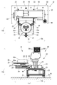
ホイールが取り付けられていないタイヤに、従来のタイヤプリンターより高精度の印刷を実行することができるタイヤプリンターを提供する。 タイヤプリンター(10)は、タイヤの側面に印刷を実行するタイヤプリンターであって、タイヤ(93)の一対の側面部分(93a)が矢印(10a)で示す上下方向において上下に向けた状態でタイヤ(93)を載置するタイヤ載置部(30)と、タイヤ載置部(30)をタイヤ(93)の周方向に回転させるDDモーター(29)と、タイヤ載置部(30)に載置されているタイヤの(93)の一対の側面部分(93a)のうち上側の側面部分(93a)に印刷を実行するインクジェットヘッド(53)と、を備えており、タイヤ載置部(30)は、一対の側面部分(93a)のうち下側の側面部分(93a)を鉛直方向の下側から支持することを特徴とする。
Description
本発明は、タイヤに印刷を実行するタイヤプリンターに関する。
従来のタイヤプリンターとして、タイヤに取り付けられたホイールを支持するホイール支持部と、ホイールを介してタイヤを支持するホイール支持部をタイヤの周方向に回転させるタイヤ回転部と、ホイールを介してホイール支持部が支持するタイヤの側面部分に印刷を実行するインクジェットヘッドと、を備えているタイヤプリンターが知られている(例えば、特許文献1参照。)。
また、従来のタイヤプリンターとして、タイヤの一対の側面部分が鉛直方向において上下に載置されるタイヤ載置部と、タイヤを載置するタイヤ載置部をタイヤの周方向に回転させるタイヤ回転部と、タイヤ載置部に載置されたタイヤの一対の側面部分のうち上側の側面部分に印刷を実行するインクジェットヘッドと、を備えているタイヤプリンターも知られている(例えば、特許文献2参照。)。このタイヤプリンターのタイヤ載置部は、タイヤの一対の側面部分のうち上側の側面部分が下側から支持されることによってタイヤが載置される。
しかしながら、特許文献1に記載されたタイヤプリンターは、ホイールが取り付けられたタイヤのみに印刷を実行するので、ホイールが取り付けられていないタイヤに印刷を実行することができないという問題がある。
一方、特許文献2に記載されたタイヤプリンターは、ホイールが取り付けられていないタイヤに印刷を実行することができる。しかしながら、特許文献2に記載されたタイヤプリンターは、タイヤの一対の側面部分が鉛直方向において上下に配置され、タイヤの一対の側面部分のうち上側の側面部分が下側から支持される。従って、タイヤの一対の側面部分のうち上側の側面部分、すなわち、インクジェットヘッドによる印刷対象の部分がタイヤの自重によって変形する可能性がある。したがって、特許文献2に記載されたタイヤプリンターは、タイヤに高精度の印刷を実行することが困難であるという問題がある。
そこで、本発明は、ホイールが取り付けられていないタイヤに、従来のタイヤプリンターより高精度の印刷を実行することができるタイヤプリンターを提供することを目的とする。
本発明のタイヤプリンターは、タイヤの側面に印刷を実行するタイヤプリンターであって、タイヤを前記タイヤの一対の側面部分が鉛直方向において上下に向けた状態で前記タイヤを載置するタイヤ載置部と、前記タイヤ載置部を前記タイヤの周方向に回転させるタイヤ回転部と、前記タイヤ載置部に載置されている前記タイヤの前記一対の側面部分のうち上側の側面部分に印刷を実行するインクジェットヘッドと、を備え、前記タイヤ載置部は、前記一対の側面部分のうち下側の側面部分を鉛直方向の下側から支持することを特徴とする。
この構成により、本発明のタイヤプリンターは、タイヤの一対の側面部分が鉛直方向において上下に配置され、タイヤ載置部によってタイヤの一対の側面部分のうち下側の側面部分が下側から支持される。従って、タイヤの一対の側面部分のうち上側の側面部分、すなわち、インクジェットヘッドによる印刷対象の部分がタイヤの自重によって変形することを、従来のタイヤプリンターより抑えることができる。したがって、本発明のタイヤプリンターは、ホイールが取り付けられていないタイヤに従来のタイヤプリンターより高精度の印刷を実行することができる。
また、本発明のタイヤプリンターにおいて、タイヤ載置部は、下側の側面部分を下側から支持する複数のタイヤ支持部と、タイヤ回転部によるタイヤの回転軸に直交する方向においてタイヤを位置決めするタイヤ位置決め部と、を備え、複数のタイヤ支持部は、それぞれ、タイヤ位置決め部を支持していても良い。
この構成により、本発明のタイヤプリンターは、タイヤ位置決め部が、タイヤ支持部に支持されていない構成と比較して、タイヤ回転部によるタイヤの回転軸に直交する方向におけるタイヤ支持部と、タイヤ位置決め部との位置精度を向上することができる。従って、タイヤ回転部によるタイヤの回転軸に直交する方向において、複数のタイヤ支持部と、タイヤ位置決め部によって位置決めされたタイヤとの位置精度を向上することができる。そのため、本発明のタイヤプリンターは、複数のタイヤ支持部によってタイヤを安定して支持することができる。したがって、本発明のタイヤプリンターは、ホイールが取り付けられていないタイヤに高精度の印刷を実行することができる。
また、本発明のタイヤプリンターにおいて、タイヤ位置決め部は、タイヤの内周部分に接触することによって、回転軸に直交する方向においてタイヤを位置決めしても良い。
この構成により、本発明のタイヤプリンターは、タイヤ位置決め部がタイヤの外周部分に接触することによってタイヤを位置決めする構成と比較して、タイヤ回転部によるタイヤの回転軸と、タイヤ位置決め部との距離が短い。従って、タイヤ回転部によるタイヤの回転軸に直交する方向において、複数のタイヤ位置決め部によって位置決めされたタイヤの中心軸と、タイヤ回転部によるタイヤの回転軸との位置のずれの量を小さくすることができる。したがって、本発明のタイヤプリンターは、ホイールが取り付けられていないタイヤをタイヤ回転部によって回転させて、インクジェットヘッドによってタイヤに高精度の印刷を実行することができる。
また、本発明のタイヤプリンターにおいて、タイヤ載置部は、複数のタイヤ支持部として3つのタイヤ支持部を備え、タイヤ支持部は、タイヤの径方向に長く配置され、3つのタイヤ支持部は、回転軸を中心とした同一の円周上に等間隔で配置されていても良い。
この構成により、本発明のタイヤプリンターは、タイヤの一対の側面部分のうち下側の側面部分が、タイヤ回転部によるタイヤの回転軸を中心とした同一の円周上に等間隔に配置されている3箇所のタイヤ支持部によって支持される。従って、タイヤの一対の側面部分のうち下側の側面部分全体を平面によって支持する構成と比較して、タイヤを安定して支持することができる。よって、本発明のタイヤプリンターは、ホイールが取り付けられていないタイヤに高精度の印刷を実行することができる。
また、本発明のタイヤプリンターにおいて、タイヤ載置部は、3つのタイヤ支持部のそれぞれに支持されているタイヤ位置決め部を径方向に同時に移動させるリンク機構を備えていても良い。
この構成により、本発明のタイヤプリンターは、タイヤ位置決め部がタイヤの径方向に移動させられた場合に、3つのタイヤ位置決め部がタイヤ回転部によるタイヤの回転軸を中心とした同一の円周上に等間隔で配置されている状態をリンク機構によって維持する。従って、3つのタイヤ位置決め部のそれぞれがタイヤの径方向に独立に移動させられる構成と比較して、タイヤ載置部においてタイヤが載置される位置が高精度に決定されることができる。よって、本発明のタイヤプリンターは、ホイールが取り付けられていないタイヤに高精度の印刷を実行することができる。
また、本発明のタイヤプリンターにおいて、タイヤ載置部は、下側の側面部分を鉛直方向の下側から支持する3つのタイヤ支持部を備え、3つのタイヤ支持部は、タイヤ回転部によるタイヤの回転軸を中心とした同一の円周上に等間隔で配置されていても良い。
この構成により、本発明のタイヤプリンターは、タイヤの一対の側面部分のうち下側の側面部分を、タイヤ回転部によるタイヤの回転軸を中心とした同一の円周上に等間隔で配置されている3箇所のタイヤ支持部によって支持する。従って、タイヤの一対の側面部分のうち下側の側面部分全体を平面によって支持する構成と比較して、タイヤを安定して支持することができる。よって、本発明のタイヤプリンターは、ホイールが取り付けられていないタイヤに高精度の印刷を実行することができる。
また、本発明のタイヤプリンターにおいて、タイヤ載置部は、タイヤ回転部によるタイヤの回転軸に直交する方向においてタイヤを位置決めする3つのタイヤ位置決め部と、3つのタイヤ位置決め部が回転軸を中心とした同一の円周上に等間隔に3つのタイヤ位置決め部をタイヤの径方向に同時に移動させるリンク機構と、を備えていても良い。
この構成により、本発明のタイヤプリンターは、タイヤ位置決め部がタイヤの径方向に移動された場合に、リンク機構によって、3つのタイヤ位置決め部がタイヤ回転部によるタイヤの回転軸を中心とした同一の円周上に等間隔に維持される。従って、3つのタイヤ位置決め部のそれぞれがタイヤの径方向に独立に移動させられる構成と比較して、タイヤ載置部においてタイヤが載置される位置が高精度に決定されることができる。よって、本発明のタイヤプリンターは、ホイールが取り付けられていないタイヤに高精度の印刷を実行することができる。
また、本発明のタイヤプリンターは、タイヤの一対の側面部分が鉛直方向において上下に配置されてタイヤに取り付けられたホイールを支持するホイール支持部を備える。タイヤ回転部は、ホイール支持部にホイールを介して支持されているタイヤをタイヤの周方向に回転させるためにホイール支持部を回転させる。インクジェットヘッドは、タイヤがホイールを介してホイール支持部に支持されている場合に、上側の側面部分の上側に印刷を実行しても良い。
この構成により、本発明のタイヤプリンターは、タイヤ回転部にホイール支持部が取り付けられることによって、ホイールが取り付けられているタイヤにも印刷を実行することができる。従って、ホイールが取り付けられていないタイヤだけでなく、ホイールが取り付けられているタイヤにも印刷を実行することができる。
本発明のタイヤプリンターは、ホイールが取り付けられていないタイヤに従来のタイヤプリンターより高精度の印刷を実行することができる。
以下、本発明の一実施形態に係るタイヤプリンターについて図面を用いて説明する。
まず、タイヤプリンター10の構成について説明する。
図1は、ホイール92が取り付けられているタイヤ91が設置されている状態での本実施の形態に係るタイヤプリンター10を正面に向かって左上方から観察した場合のタイヤプリンター10の外観斜視図である。図2は、図1に示す状態でのタイヤプリンター10を正面に向かって右上方から観察した場合のタイヤプリンター10の外観斜視図である。図3は、図1に示す状態でのタイヤプリンター10の正面図である。図4は、図1に示す状態でのタイヤプリンター10の平面図である。
図1~図4に示すように、タイヤプリンター10は、タイヤ91などのタイヤを支持するタイヤ支持装置20と、タイヤ支持装置20に支持されているインクジェットプリンター50とを備えている。
タイヤ支持装置20は、床99に設置される4本の脚部21と、矢印10aで示す鉛直方向、すなわち、上下方向において脚部21の上側に配置されていて、脚部21に支持されている直方体状の枠体22と、を備えている。
図5は、図1に示す状態でのタイヤ支持装置20の側面断面図である。
図1~図5に示すように、タイヤ支持装置20は、枠体22の上側で枠体22に支持されていて、矢印10aで示す上下方向と、上下方向に直交する矢印10bで示す前後方向との両方に直交する矢印10cで示す左右方向に互いに離れて配置されている一対のスライドレール23と、一対のスライドレール23に支持されているスライド板24と、枠体22の上側で枠体22に支持されていて、前後方向に互いに離れて配置されている一対のショックアブソーバー(shock absorber)25と、スライド板24における後側の下面に取り付けられていて、ショックアブソーバー25に接触することによってスライド板24の前後方向における移動を規制する停止用部材26と、スライド板24の前端部に取り付けられていて、利用者によって掴まれるハンドル27と、スライドレール23およびスライド板24に挿入され、スライド板24が枠体22に対して前後方向に移動しないようにスライド板24を固定するピン28とを備えている。
一対のスライドレール23は、矢印10bで示す前後方向に長く設けられ、スライド板24を枠体22に対して前後方向に移動可能に支持している。
タイヤ支持装置20は、スライド板24に支持されているDD(Direct Drive)モーター29と、DDモーター29に回転可能に支持されていて、タイヤが載置されるタイヤ載置部30とを備えている。
図6は、ホイールが取り付けられていないタイヤ93が設置されている状態でのタイヤプリンター10の正面図である。図7は、図6に示す状態でのタイヤプリンター10の平面図である。図8は、図6に示す状態でのタイヤ支持装置20の側面断面図である。図9は、タイヤ支持装置20の一部の斜視図である。図10は、タイヤ支持装置20の一部の正面図である。図11は、タイヤ支持装置20の一部の平面図である。
図6~図11に示すように、タイヤ支持装置20は、後述のシャフト41(図3参照。)がタイヤ載置部30から取り外されている。
タイヤ載置部30は、DDモーター29に回転可能に支持されている円板31と、円板31上に固定されている3つのレール32と、3つのレール32のそれぞれに1つずつ支持されていて、タイヤ93を固定する3つのストッパー33とを備えている。
タイヤ載置部30は、タイヤ93をタイヤ93の一対の側面部分93aが矢印10aで示す上下方向において上下に載置する。タイヤ載置部30は、タイヤ93をタイヤ93の一対の側面部分93aのうち下側の側面部分93aを鉛直方向の下側から支持して、載置する。
円板31は、シャフト41を固定するためのシャフト固定用孔31aを中央に備える。
円板31は、3つのレール32をDDモーター29によるタイヤ93の回転軸90a(図8参照。)を中心とした同一の円周上に、等間隔に備える。レール32は、タイヤ93の一対の側面部分93aのうち下側の側面部分93aを鉛直方向下側から支持するタイヤ支持部を構成している。レール32は、タイヤ93の矢印90b(図11参照。)で示す径方向に長く延び、ストッパー33を矢印90bで示す径方向に移動可能に支持している。
3つのストッパー33は、タイヤ93の回転軸90aを中心として等間隔の角度で配置されている。ストッパー33は、タイヤ93の矢印90bで示す径方向のうち、DDモーター29によるタイヤ93の回転軸90aから遠ざかる方向にタイヤ93の内周部分93bに接触することによってタイヤ93を固定する。ストッパー33は、回転軸90aに直交する方向においてタイヤ93を位置決めするタイヤ位置決め部を構成している。ストッパー33は、上部に開口している貫通孔33aに挿入されている図示していないネジによって、レール32に固定される。
なお、DDモーター29は、タイヤ載置部30に載置されているタイヤ93をタイヤ93の矢印90c(図11参照。)で示す周方向に回転するように、タイヤ載置部30を回転させる。DDモーター29はタイヤ回転部を構成している。
図3および図5に示すように、タイヤ支持装置20は、タイヤ載置部30の円板31のシャフト固定用孔31aに着脱可能に設けられるシャフト41と、シャフト41に取り付けられるナット42と、を備えている。
シャフト41は、タイヤ91に取り付けられたホイール92を支持するホイール支持部を構成している。
ナット42は、タイヤ91のホイール92に挿入されるシャフト41にホイール92を締結する。シャフト41は円板31に固定される。従って、円板31にシャフト41を介してタイヤ91が固定される。
シャフト41は、一対の側面部分91aが矢印10aで示す上下方向に上下に配置されるタイヤ91のホイール92を介して、タイヤ91を支持する。タイヤ91がホイール92を介してシャフト41に支持されている場合、タイヤ91はタイヤ載置部30に載置されていない。
なお、DDモーター29は、円板31を介してシャフト41を回転させ、シャフト41にホイール92を介して支持されているタイヤ91をタイヤ91の矢印90cで示す周方向に回転させる。
図1~図5に示すように、タイヤ支持装置20は、一対のプリンター上下機構43と、ハンドル44と、図示しない伝達機構と、を備える。一対のプリンター上下機構43は、インクジェットプリンター50を支持する。また、一対のプリンター上下機構43は、矢印10aによって示す上下方向に移動可能に枠体22に支持される。ハンドル44は、利用者によって回転されることにより、プリンター上下機構43を上下方向に移動させる。伝達機構は、ハンドル44の回転に伴ってプリンター上下機構43を上下方向に移動させる。
一対のプリンター上下機構43は、一対のスライドレール23を挟み、矢印10cで示す左右方向に互いに対向して配置されている。
図1~図4、図6および図7に示すように、インクジェットプリンター50は、矢印10cで示す左右方向に延びるガイドレール51と、矢印10cによって示す左右方向に移動可能にガイドレール51に支持されているキャリッジ52と、キャリッジ52に搭載されていて、タイヤ91に向けてインク滴を吐出する複数のインクジェットヘッド53と、インクジェットヘッド53にインクを供給する複数のタンク54と、を備えている。
図1~図4に示すように、インクジェットヘッド53は、ホイール92を介してシャフト41に支持されているタイヤ91の一対の側面部分91aのうち上側の側面部分91aの表面に印刷を実行する。また、インクジェットヘッド53は、図6および図7に示すように、タイヤ載置部30に載置されているタイヤ93の一対の側面部分93aのうち上側の側面部分93aの上側に印刷を実行する。
図12は、タイヤプリンター10のブロック図である。
図12に示すように、タイヤプリンター10は、種々の操作によって情報が入力されるボタンなどの入力デバイスである操作部61と、種々の情報を表示するLCD(Liquid Crystal Display)などの表示デバイスである表示部62と、PC(Personal Computer)などの外部の装置と通信を行う通信デバイスである通信部63と、上述したDDモーター29およびインクジェットヘッド53と、キャリッジ52(図1参照。)をガイドレール51(図1参照。)に沿って矢印10c(図1参照。)で示す左右方向に移動させるためのキャリッジ駆動装置64と、各種のデータを記憶するEEPROM(Electrically Erasable Programmable Read Only Memory)などの記憶デバイスである記憶部65と、タイヤプリンター10全体を制御する制御部66と、を備えている。
制御部66は、例えば、CPU(Central Processing Unit)と、プログラムおよび各種のデータを予め記憶しているROM(Read Only Memory)と、CPUの作業領域として用いられるRAM(Random Access Memory)と、を備えている。CPUは、ROMまたは記憶部65に記憶されているプログラムを順次読み出して実行する。
次に、タイヤプリンター10へのタイヤの設置方法について説明する。
まず、ホイール92が取り付けられているタイヤ91の設置方法について説明する。
図13(a)は、スライド板24が引き出されている状態でのタイヤプリンター10の平面図である。図13(b)は、図13(a)に示す状態でのタイヤプリンター10の側面図である。
まず、利用者は、スライドレール23およびスライド板24からピン28を外した後、ハンドル27を掴み、スライド板24を矢印10bで示す前後方向のうち前方向に移動させ、スライド板24をインクジェットプリンター50の下から図13に示すように引き出す。利用者は、スライドレール23およびスライド板24にピン28を挿入し、スライド板24を位置決めする。利用者は、円板31のシャフト固定用孔31aにシャフト41を取り付ける。
図14(a)は、ホイール92が取り付けられているタイヤ91を支持していてスライド板24が引き出されている状態でのタイヤプリンター10の平面図である。図14(b)は、図14(a)に示す状態でのタイヤプリンター10の側面図である。
利用者は、図13に示すようにスライド板24を引き出した後、タイヤ91に取り付けられているホイール92を、円板31のシャフト固定用孔31aに取り付けられているシャフト41に取り付ける。そして、図14に示すように、利用者は、ナット42をシャフト41に取り付け、シャフト41によってホイール92を介してタイヤ91を円板31に固定する。
次いで、利用者は、スライド板24がインクジェットプリンター50の下に位置する場合に、タイヤ91がインクジェットプリンター50と干渉しないように、ハンドル44を回してインクジェットプリンター50の矢印10aで示す上下方向の位置を調整する。
次いで、利用者は、スライドレール23およびスライド板24からピン28を外し、ハンドル27を掴み、スライド板24を矢印10bで示す前後方向のうち後方向に移動させる。スライド板24はインクジェットプリンター50の下に収納される。利用者は、スライドレール23およびスライド板24にピン28を挿入し、スライド板24を位置決めする。
最後に、利用者は、インクジェットプリンター50によってタイヤ91に印刷を実行することができるように、ハンドル44を回してインクジェットプリンター50の矢印10aで示す上下方向の位置を調整する。
以上のようにして、タイヤ91は、図1~図4に示すようにタイヤプリンター10に設置される。
次に、ホイールが取り付けられていないタイヤ93の設置方法について説明する。
まず、利用者は、スライドレール23およびスライド板24からピン28を外した後、ハンドル27を掴み、スライド板24を矢印10bで示す前後方向のうち前方向に移動させる。スライド板24はインクジェットプリンター50の下から図13に示すように引き出される。利用者は、スライドレール23およびスライド板24にピン28を挿入し、スライド板24の位置決めする。利用者は、円板31のシャフト固定用孔31aにシャフト41が取り付けられている場合、円板31のシャフト固定用孔31aからシャフト41を取り外す。
図13に示すように、利用者は、スライド板24を引き出した後、ストッパー33の貫通孔33aに挿入されているネジを緩めてレール32に対するストッパー33の固定を解除して、3つのストッパー33が互いに近付くようにストッパー33をレール32に沿って矢印90bで示す方向に移動させる。すなわち、利用者は、レール32上のストッパー33をタイヤ93の矢印90bで示す径方向のうちDDモーター29によるタイヤ93の回転軸90aに近付く方向に移動させる。
次いで、利用者は、3つのストッパー33がタイヤ93の内周部分93bに囲まれるように、3つのレール32の上にタイヤ93を載置する。
図15(a)は、ホイールが取り付けられていないタイヤ93を支持していてスライド板24が引き出されている状態でのタイヤプリンター10の平面図である。図15(b)は、図15(a)に示す状態でのタイヤプリンター10の側面図である。
利用者は、3つのレール32の上にタイヤ93を載置する。利用者は、レール32上のストッパー33をタイヤ93の矢印90bで示す径方向のうちDDモーター29によるタイヤ93の回転軸90aから遠ざかる方向に移動させ、3つのストッパー33をタイヤ93の内周部分93bに接触させる。利用者は、ストッパー33の貫通孔33aに挿入されているネジを締めてレール32に対してストッパー33を固定する。図15に示すように、タイヤ93はストッパー33によってタイヤ載置部30に固定される。
次いで、利用者は、スライド板24がインクジェットプリンター50の下に位置する場合に、タイヤ93がインクジェットプリンター50と干渉しないように、ハンドル44を回してインクジェットプリンター50の矢印10aで示す上下方向の位置を調整する。
次いで、利用者は、スライドレール23およびスライド板24からピン28を外した後、ハンドル27を掴み、スライド板24を矢印10bで示す前後方向のうち後方向に移動させる。スライド板24はインクジェットプリンター50の下に収納される。利用者は、スライドレール23およびスライド板24にピン28を挿入し、スライド板24を位置決めする。
最後に、利用者は、インクジェットプリンター50によってタイヤ93に印刷を実行できるように、ハンドル44を回してインクジェットプリンター50の矢印10aで示す上下方向の位置を調整する。
以上のようにして、タイヤ93は、図6および図7に示すようにタイヤプリンター10に設置される。
次に、タイヤプリンター10に設置されたタイヤへの印刷について説明する。
タイヤプリンター10の制御部66は、外部から送信されてきた印刷データを、通信部63を介して受信すると、この印刷データに基づいてDDモーター29、インクジェットヘッド53、およびキャリッジ駆動装置64を制御し、インクジェットヘッド53によってタイヤ91、93などのタイヤへの印刷を実行する。
具体的には、制御部66は、キャリッジ駆動装置64を制御してキャリッジ52をガイドレール51に沿って矢印10cで示す左右方向に移動させることによって、キャリッジ52に搭載されているインクジェットヘッド53をタイヤに対して矢印10cで示す左右方向に相対的に移動させる。このとき、制御部66は、タイヤに向けてインクジェットヘッド53によってインク滴を吐出させることによって、矢印10cで示す左右方向における印刷を実行する。そして、制御部66は、矢印10cで示す左右方向における印刷が終了する度に、DDモーター29を制御してタイヤを回転させることによって、タイヤに対するインクジェットヘッド53の印刷位置を変更する。そして、制御部66は、新たな印刷位置において再び矢印10cで示す左右方向における印刷を実行する。
以上に説明したように、タイヤプリンター10は、タイヤ93の一対の側面部分93aが矢印10aで示す上下方向において上下に、タイヤ93の一対の側面部分93aのうち下側の側面部分93aを鉛直方向の下側から支持する従って、タイヤ93の一対の側面部分93aのうち上側の側面部分93a、すなわち、インクジェットヘッド53による印刷対象の部分がタイヤ93の自重によって変形することを従来のタイヤプリンターより抑えることができる。したがって、タイヤプリンター10は、ホイールが取り付けられていないタイヤ93に従来のタイヤプリンターより高精度の印刷を実行することができる。
タイヤプリンター10は、ストッパー33がレール32に支持されていない構成と比較して、DDモーター29によるタイヤ93の回転軸90aに直交する方向におけるレール32と、ストッパー33との位置精度を向上させることができる。従って、回転軸90aに直交する方向において、3つのレール32と、ストッパー33によって位置決めされたタイヤ93との位置精度を向上することができる。そのため、タイヤプリンター10は、3つのレール32によってタイヤ93を安定して支持することができる。したがって、タイヤプリンター10は、ホイールが取り付けられていないタイヤ93に高精度の印刷を実行することができる。
タイヤプリンター10は、ストッパー33がタイヤ93の内周部分に接触することによって回転軸90aに直交する方向においてタイヤ93を位置決めする。この構成により、タイヤプリンター10は、ストッパー33がタイヤ93の外周部分に接触することによってタイヤ93を位置決めする構成と比較して、回転軸90aと、ストッパー33との距離が短い。よって、回転軸90aに直交する方向において、3つのストッパー33によって位置決めされたタイヤ93の中心軸と、回転軸90aとの位置のずれの量を小さくすることができる。したがって、タイヤプリンター10は、ホイールが取り付けられていないタイヤ93をDDモーター29によって回転させてインクジェットヘッド53によって印刷を実行する場合に、タイヤ93に高精度の印刷を実行することができる。
タイヤプリンター10は、タイヤ93の一対の側面部分93aのうち下側の側面部分93aを、DDモーター29によるタイヤ93の回転軸90aを中心とした同一の円周上に等間隔で配置されている3箇所のレール32によって支持する。よって、タイヤ93の一対の側面部分93aのうち下側の側面部分93a全体を平面によって支持する構成と比較して、タイヤ93を安定して支持することができる。したがって、タイヤプリンター10は、ホイールが取り付けられていないタイヤ93に高精度の印刷を実行することができる。
なお、タイヤプリンター10は、タイヤ93の一対の側面部分93aのうち下側の側面部分93a全体を平面によって支持する構成であっても良い。
タイヤプリンター10は、レール32の機能として、タイヤ93を支持する機能だけでなく、ストッパー33をタイヤ93の矢印90bで示す径方向に移動可能に支持する機能を備えている。よって、タイヤ93を支持する機能と、ストッパー33をタイヤ93の径方向に移動可能に支持する機能とを別々の部材によって実現する構成と比較して、小型化することができる。
なお、タイヤプリンター10は、タイヤ93を支持する機能と、ストッパー33をタイヤ93の径方向に移動可能に支持する機能とを別々の部材によって実現する構成であっても良い。
タイヤプリンター10は、DDモーター29にシャフト41が取り付けられることによって、ホイール92が取り付けられているタイヤ91にも印刷を実行することができるので、ホイールが取り付けられていないタイヤ93だけでなく、ホイール92が取り付けられているタイヤ91にも印刷を実行することができる。
なお、タイヤプリンター10は、ホイールが取り付けられていないタイヤ93のみに印刷を実行することができる構成であっても良い。
以上において説明したタイヤ載置部30は、3つのストッパー33がレール32に対してタイヤ93の矢印90bで示す径方向にそれぞれ独立に移動可能である。しかしながら、例えば図16および図17に示すように、タイヤ載置部30は、DDモーター29によるタイヤ93の回転軸90aを中心とした同一の円周上に等間隔で配置される3つのストッパー33をタイヤ93の矢印90bで示す径方向に同時に移動させるリンク機構34を備えていても良い。
図16は、3つのストッパー33が互いに近付いている状態でのタイヤ載置部30の底面図である。図17は、3つのストッパー33が互いに離れている状態でのタイヤ載置部30の底面図である。
図16および図17に示すように、リンク機構34は、矢印90cで示す方向に回転可能に円板31に支持されている輪状板35と、レール32の長手方向と同一の方向に延びるレール32の下側に配置されている3つのレール36と、ストッパー33に連結されていて、レール36に沿って移動可能である3つの長板37と、輪状板35および長板37を連結している3つのリンク38と、を備えている。
リンク38は、回転可能に輪状板35に支持されている軸38aと、回転可能に長板37に支持されている軸38bと、を備えている。
なお、タイヤプリンター10がリンク機構34を備えている場合、円板31およびレール32は、ストッパー33および長板37を連結する図示していない部分を移動可能に支持する矢印90bで示す方向に延びる図示していない長穴を有する。
タイヤ載置部30は、リンク機構34を備えている場合、3つのストッパー33のうち何れか1つがレール32に沿って矢印90bで示す方向に移動すると、リンク機構34を介して、残りの2つのストッパー33も同様にそれぞれレール32に沿って矢印90bで示す方向に移動する。
タイヤプリンター10は、リンク機構34を備えている場合、ストッパー33がタイヤ93の矢印90bで示す径方向に移動したときに、リンク機構34によって、3つのストッパー33がDDモーター29によるタイヤ93の回転軸90aを中心とした同一の円周上に等間隔に維持される。従って、3つのストッパー33のそれぞれがタイヤ93の径方向に独立に移動させられる構成と比較して、タイヤ載置部30においてタイヤ93が載置される位置を高精度に決定できる。したがって、タイヤプリンター10は、リンク機構34を備えている場合、ホイールが取り付けられていないタイヤ93に高精度の印刷を実行ことができる。
以上においては、タイヤプリンター10は、3つのレール32がDDモーター29によるタイヤ93の回転軸90aを中心とした同一の円周上に等間隔で配置されているが、3つのレール32が回転軸90aを中心とした同一の円周上に等間隔で配置されていなくても良い。同様に、タイヤプリンター10は、3つのストッパー33が回転軸90aを中心とした同一の円周上に等間隔で配置されているが、3つのストッパー33が回転軸90aを中心とした同一の円周上に等間隔で配置されていなくても良い。
また、以上においては、タイヤプリンター10は、ストッパー33がタイヤ93の内周部分に接触することによって回転軸90aに直交する方向においてタイヤ93を位置決めする。しかしながら、タイヤプリンター10は、3つのストッパー33の少なくとも1つがタイヤ93の外周部分に接触することによって回転軸90aに直交する方向においてタイヤ93を位置決めしても良い。
また、以上においては、タイヤプリンター10は、レール32およびストッパー33を3つずつ備えている。しかしながら、タイヤプリンター10は、レール32およびストッパー33を、それぞれ、3つ以外の複数の個数備えていても良い。
10 タイヤプリンター
10a 矢印(鉛直方向を示す矢印)
29 DDモーター(タイヤ回転部)
30 タイヤ載置部
32 レール(タイヤ支持部)
33 ストッパー(タイヤ位置決め部)
34 リンク機構
41 シャフト(ホイール支持部)
53 インクジェットヘッド
90a 回転軸
90b 矢印(タイヤの径方向を示す矢印)
90c 矢印(タイヤの周方向を示す矢印)
91 タイヤ
91a 側面部分
92 ホイール
93 タイヤ
93a 側面部分
93b 内周部分
10a 矢印(鉛直方向を示す矢印)
29 DDモーター(タイヤ回転部)
30 タイヤ載置部
32 レール(タイヤ支持部)
33 ストッパー(タイヤ位置決め部)
34 リンク機構
41 シャフト(ホイール支持部)
53 インクジェットヘッド
90a 回転軸
90b 矢印(タイヤの径方向を示す矢印)
90c 矢印(タイヤの周方向を示す矢印)
91 タイヤ
91a 側面部分
92 ホイール
93 タイヤ
93a 側面部分
93b 内周部分
Claims (8)
- タイヤの側面に印刷を実行するタイヤプリンターであって、
前記タイヤの一対の側面部分を鉛直方向において上下に向けた状態で前記タイヤを載置するタイヤ載置部と、
前記タイヤ載置部を前記タイヤの周方向に回転させるタイヤ回転部と、
前記タイヤ載置部に載置されている前記タイヤの前記一対の側面部分のうち上側の側面部分に印刷を実行するインクジェットヘッドと、
を備え、
前記タイヤ載置部は、
前記一対の側面部分のうち下側の側面部分を鉛直方向の下側から支持することを特徴とするタイヤプリンター。 - 前記タイヤ載置部は、
前記下側の側面部分を鉛直方向の下側から支持する複数のタイヤ支持部と、
前記タイヤ回転部による前記タイヤの回転軸に直交する方向において前記タイヤを位置決めするタイヤ位置決め部とを備え、
各前記タイヤ支持部は、
前記タイヤ位置決め部を支持していることを特徴とする請求項1に記載のタイヤプリンター。 - 前記タイヤ位置決め部は、
前記タイヤの内周部分に接触することによって、前記回転軸に直交する方向において前記タイヤを位置決めすることを特徴とする請求項2に記載のタイヤプリンター。 - 前記タイヤ載置部は、
前記複数のタイヤ支持部が3つのタイヤ支持部であり、
前記タイヤ支持部は、
前記タイヤの径方向に延び、
前記3つのタイヤ支持部は、
前記回転軸を中心とした同一の円周上に等間隔に配置されていることを特徴とする請求項2または請求項3に記載のタイヤプリンター。 - 前記タイヤ載置部は、
前記3つのタイヤ支持部の各前記タイヤ支持部に支持されている前記タイヤ位置決め部を、前記径方向に同時に移動させるリンク機構を備えていることを特徴とする請求項4に記載のタイヤプリンター。 - 前記タイヤ載置部は、
前記下側の側面部分を鉛直方向の下側から支持する3つのタイヤ支持部を備えており、
前記3つのタイヤ支持部は、
前記タイヤ回転部による前記タイヤの回転軸を中心とした同一の円周上に等間隔で配置されていることを特徴とする請求項1に記載のタイヤプリンター。 - 前記タイヤ載置部は、
前記タイヤ回転部による前記タイヤの回転軸に直交する方向において前記タイヤを位置決めする3つのタイヤ位置決め部と、
前記回転軸を中心とした同一の円周上に等間隔で配置される前記3つのタイヤ位置決め部を前記タイヤの径方向に同時に移動するリンク機構と、
を備えていることを特徴とする請求項1に記載のタイヤプリンター。 - タイヤの側面に印刷を実行するタイヤプリンターであって、
前記タイヤが有するホイールを支持して前記タイヤの一対の側面部分を鉛直方向において上下に配置させるホイール支持部と、
前記ホイール支持部を回転させて前記タイヤを当該タイヤの周方向に回転させるタイヤ回転部と、
前記ホイール支持部に支持されている前記タイヤの前記一対の側面部分のうち上側の側面部分に印刷を実行するインクジェットヘッドと、
を備えることを特徴とするタイヤプリンター。
Applications Claiming Priority (2)
| Application Number | Priority Date | Filing Date | Title |
|---|---|---|---|
| JP2014085670A JP6308854B2 (ja) | 2014-04-17 | 2014-04-17 | タイヤプリンター |
| JP2014-085670 | 2014-04-17 |
Publications (1)
| Publication Number | Publication Date |
|---|---|
| WO2015159967A1 true WO2015159967A1 (ja) | 2015-10-22 |
Family
ID=54324168
Family Applications (1)
| Application Number | Title | Priority Date | Filing Date |
|---|---|---|---|
| PCT/JP2015/061795 Ceased WO2015159967A1 (ja) | 2014-04-17 | 2015-04-17 | タイヤプリンター |
Country Status (2)
| Country | Link |
|---|---|
| JP (1) | JP6308854B2 (ja) |
| WO (1) | WO2015159967A1 (ja) |
Cited By (3)
| Publication number | Priority date | Publication date | Assignee | Title |
|---|---|---|---|---|
| EP3381669A1 (de) | 2017-03-30 | 2018-10-03 | Continental Reifen Deutschland GmbH | Verfahren zur typisierung eines fahrzeugreifens und fertigungsanlage zur durchführung des verfahrens |
| CN109249691A (zh) * | 2018-10-30 | 2019-01-22 | 盛旺汽车零部件(昆山)有限公司 | 一种汽车轮毂表面双色图案移印装置 |
| CN110433993A (zh) * | 2019-08-31 | 2019-11-12 | 江苏托普车轮有限公司 | 一种汽车轮胎快速喷胶装置 |
Families Citing this family (1)
| Publication number | Priority date | Publication date | Assignee | Title |
|---|---|---|---|---|
| JP6922577B2 (ja) * | 2017-09-13 | 2021-08-18 | 住友ゴム工業株式会社 | カラーライン塗布装置 |
Citations (5)
| Publication number | Priority date | Publication date | Assignee | Title |
|---|---|---|---|---|
| JPH03504946A (ja) * | 1988-05-06 | 1991-10-31 | スタールグルーバー オットー グルーバー ゲーエムベーハー ウント ツェーオー | 回転対称なゴム物体に飾りリングおよび類似のものを取り付けるための装置 |
| JP2004003874A (ja) * | 2002-03-29 | 2004-01-08 | Yamato Scale Co Ltd | タイヤ用ダイナミックバランサのタイヤ保持方法及びタイヤ保持装置 |
| WO2011096422A1 (ja) * | 2010-02-02 | 2011-08-11 | 株式会社ブリヂストン | タイヤ選別装置 |
| JP2012101392A (ja) * | 2010-11-08 | 2012-05-31 | Bridgestone Corp | タイヤ表面印刷方法およびタイヤ用印刷装置 |
| JP2013224055A (ja) * | 2012-04-19 | 2013-10-31 | Bridgestone Corp | タイヤ保持具及びタイヤ印刷方法並びにタイヤ印刷装置 |
Family Cites Families (5)
| Publication number | Priority date | Publication date | Assignee | Title |
|---|---|---|---|---|
| JPH04223142A (ja) * | 1990-12-26 | 1992-08-13 | Bridgestone Corp | タイヤの側壁に縞模様を付けるための方法および装置 |
| JP4309139B2 (ja) * | 2003-01-10 | 2009-08-05 | 横浜ゴム株式会社 | タイヤマーキングシステム |
| JP2010042645A (ja) * | 2008-08-18 | 2010-02-25 | Bridgestone Corp | 塗布装置及び塗布方法 |
| JP5943689B2 (ja) * | 2012-04-19 | 2016-07-05 | 株式会社ブリヂストン | タイヤ印刷方法及びタイヤ印刷装置 |
| JP5886679B2 (ja) * | 2012-04-19 | 2016-03-16 | 株式会社ブリヂストン | タイヤ印刷装置及びタイヤ印刷方法 |
-
2014
- 2014-04-17 JP JP2014085670A patent/JP6308854B2/ja active Active
-
2015
- 2015-04-17 WO PCT/JP2015/061795 patent/WO2015159967A1/ja not_active Ceased
Patent Citations (5)
| Publication number | Priority date | Publication date | Assignee | Title |
|---|---|---|---|---|
| JPH03504946A (ja) * | 1988-05-06 | 1991-10-31 | スタールグルーバー オットー グルーバー ゲーエムベーハー ウント ツェーオー | 回転対称なゴム物体に飾りリングおよび類似のものを取り付けるための装置 |
| JP2004003874A (ja) * | 2002-03-29 | 2004-01-08 | Yamato Scale Co Ltd | タイヤ用ダイナミックバランサのタイヤ保持方法及びタイヤ保持装置 |
| WO2011096422A1 (ja) * | 2010-02-02 | 2011-08-11 | 株式会社ブリヂストン | タイヤ選別装置 |
| JP2012101392A (ja) * | 2010-11-08 | 2012-05-31 | Bridgestone Corp | タイヤ表面印刷方法およびタイヤ用印刷装置 |
| JP2013224055A (ja) * | 2012-04-19 | 2013-10-31 | Bridgestone Corp | タイヤ保持具及びタイヤ印刷方法並びにタイヤ印刷装置 |
Cited By (4)
| Publication number | Priority date | Publication date | Assignee | Title |
|---|---|---|---|---|
| EP3381669A1 (de) | 2017-03-30 | 2018-10-03 | Continental Reifen Deutschland GmbH | Verfahren zur typisierung eines fahrzeugreifens und fertigungsanlage zur durchführung des verfahrens |
| DE102017205413A1 (de) | 2017-03-30 | 2018-10-04 | Continental Reifen Deutschland Gmbh | Verfahren zur Typisierung eines Fahrzeugreifens und Fertigungsanlage zur Durchführung des Verfahrens |
| CN109249691A (zh) * | 2018-10-30 | 2019-01-22 | 盛旺汽车零部件(昆山)有限公司 | 一种汽车轮毂表面双色图案移印装置 |
| CN110433993A (zh) * | 2019-08-31 | 2019-11-12 | 江苏托普车轮有限公司 | 一种汽车轮胎快速喷胶装置 |
Also Published As
| Publication number | Publication date |
|---|---|
| JP2015205409A (ja) | 2015-11-19 |
| JP6308854B2 (ja) | 2018-04-11 |
Similar Documents
| Publication | Publication Date | Title |
|---|---|---|
| EP1918113B1 (en) | Three-dimensional printer | |
| CN104602914B (zh) | 喷墨打印机以及打印方法 | |
| JP6308854B2 (ja) | タイヤプリンター | |
| JP2013539722A5 (ja) | ||
| US9108447B1 (en) | Printer | |
| CN104582967A (zh) | 喷墨打印机、被打印体保持构件、以及打印方法 | |
| US9796196B2 (en) | Carriage and liquid jet recording apparatus | |
| US9802430B2 (en) | Ink discharge unit and unit assembling method | |
| JP2012161992A (ja) | 液滴吐出ヘッドの位置決め機構、液滴吐出装置、画像形成装置、液滴吐出ヘッドの位置決め方法ならびに交換方法 | |
| JP5100491B2 (ja) | プリンタ装置 | |
| JP4399432B2 (ja) | プリンター装置 | |
| JP2009184119A (ja) | 3次元プリンタ | |
| CN112085648A (zh) | 立体物制造方法和立体物 | |
| US11511541B2 (en) | Inkjet head cleaning unit and cleaning system | |
| JP2016179589A (ja) | インクジェットプリンター | |
| JP5979826B2 (ja) | 液体吐出ヘッド及び液体吐出装置 | |
| JP7694113B2 (ja) | 移動機構および印刷装置 | |
| JP6848300B2 (ja) | 印刷装置 | |
| EP2614959B1 (en) | Device for cleaning and closing print cartridges and closing element for closing print cartridges | |
| JP7017186B2 (ja) | 印刷装置 | |
| JPWO2017086006A1 (ja) | 円筒印刷用治具及び円筒印刷用治具を用いた印刷装置 | |
| US9889688B2 (en) | Printing unit and printer | |
| JP6545525B2 (ja) | インクジェットプリンタの保守部材高さ調節システム、インクジェットプリンタの保守部材高さ調節方法、及び、インクジェットプリンタ | |
| JP2008068513A (ja) | 自走式印字装置 | |
| JP6403619B2 (ja) | インクジェットプリンター |
Legal Events
| Date | Code | Title | Description |
|---|---|---|---|
| 121 | Ep: the epo has been informed by wipo that ep was designated in this application |
Ref document number: 15780395 Country of ref document: EP Kind code of ref document: A1 |
|
| NENP | Non-entry into the national phase |
Ref country code: DE |
|
| 122 | Ep: pct application non-entry in european phase |
Ref document number: 15780395 Country of ref document: EP Kind code of ref document: A1 |