WO2015159888A1 - プッシュプルキャップ - Google Patents
プッシュプルキャップ Download PDFInfo
- Publication number
- WO2015159888A1 WO2015159888A1 PCT/JP2015/061490 JP2015061490W WO2015159888A1 WO 2015159888 A1 WO2015159888 A1 WO 2015159888A1 JP 2015061490 W JP2015061490 W JP 2015061490W WO 2015159888 A1 WO2015159888 A1 WO 2015159888A1
- Authority
- WO
- WIPO (PCT)
- Prior art keywords
- spout
- cap
- liquid
- overcap
- push
- Prior art date
- Legal status (The legal status is an assumption and is not a legal conclusion. Google has not performed a legal analysis and makes no representation as to the accuracy of the status listed.)
- Ceased
Links
Images

Classifications
-
- B—PERFORMING OPERATIONS; TRANSPORTING
- B65—CONVEYING; PACKING; STORING; HANDLING THIN OR FILAMENTARY MATERIAL
- B65D—CONTAINERS FOR STORAGE OR TRANSPORT OF ARTICLES OR MATERIALS, e.g. BAGS, BARRELS, BOTTLES, BOXES, CANS, CARTONS, CRATES, DRUMS, JARS, TANKS, HOPPERS, FORWARDING CONTAINERS; ACCESSORIES, CLOSURES, OR FITTINGS THEREFOR; PACKAGING ELEMENTS; PACKAGES
- B65D47/00—Closures with filling and discharging, or with discharging, devices
- B65D47/04—Closures with discharging devices other than pumps
- B65D47/20—Closures with discharging devices other than pumps comprising hand-operated members for controlling discharge
- B65D47/24—Closures with discharging devices other than pumps comprising hand-operated members for controlling discharge with poppet valves or lift valves, i.e. valves opening or closing a passageway by a relative motion substantially perpendicular to the plane of the seat
- B65D47/241—Closures with discharging devices other than pumps comprising hand-operated members for controlling discharge with poppet valves or lift valves, i.e. valves opening or closing a passageway by a relative motion substantially perpendicular to the plane of the seat the valve being opened or closed by actuating a cap-like element
- B65D47/243—Closures with discharging devices other than pumps comprising hand-operated members for controlling discharge with poppet valves or lift valves, i.e. valves opening or closing a passageway by a relative motion substantially perpendicular to the plane of the seat the valve being opened or closed by actuating a cap-like element moving linearly, i.e. without rotational motion
Definitions
- the present invention relates to a push-pull cap that pushes and pulls an overcap to open and close and a liquid dispensing container including the push-pull cap.
- Push-pull cap opens and closes the cap spout by pushing (pushing) and pulling (pull).
- Patent Document 2 discloses a liquid detergent product that removes an integral sealing member at a spout when in use.
- a spout is formed in the ceiling of the cap, and the cap is formed on the inner side of the cap so as to extend around the spout opening or on the inner surface of the spout.
- a shielding wall that surrounds the opening is provided in the vicinity.
- the inclination part is formed in the container side opening of the shielding wall, and liquid return promotion is aimed at by the liquid covering this inclination part.
- Patent Document 3 relating to the push-pull cap, liquid return is promoted by installing an asymmetrical step on the inner wall of the cylindrical portion.
- JP 2008-137701 A JP-A-11-70962 Japanese Patent No. 3955420
- the existing suppression mechanism such as the above-mentioned patent document does not sufficiently return the liquid. It was confirmed that the bubble was blown out.
- the present invention provides a push-pull cap that realizes a mechanism for more efficiently returning the liquid accumulated in the vicinity of the spout after discharging the liquid to the inside of the bottle.
- the present invention is a push-pull cap that is attached to a container (bottle) and squeezes the container to pour out the contents.
- the cap body and a rod-like plug body standing on the cap body are attached to the cap body.
- It has an overcap that is liquid-tightly mounted and can be moved up and down, and this overcap has a spout for pouring out the liquid to the top and a cylindrical portion that hangs down to the container surrounding the spout
- the push-pull cap is characterized in that the inner shape of the cylindrical portion gradually expands downward from the spout.
- the opening area of the spout and S 1 liquid flow paths at the distal end of the fitting portion between the overcap in the rod-like plug tip side of the cap body
- the area is S 2
- the internal shape of the cylindrical portion inside the overcap has a conical shape that gradually expands downward from the spout.
- the “liquid remaining inside the spout” has the most influence on the occurrence of bubble jumping.
- the overcap has a spout for pouring liquid into the top and has a tubular portion that surrounds the spout and hangs down on the container side.
- the shape gradually expands downward from the spout, making it difficult for the liquid to stay locally, and when the container is restored after the contents have been discharged, it is smoothly drawn into the cap and efficiently dropped. Can do.
- the existing suppression mechanism may not return the liquid sufficiently. Residual liquid near the outlet can be efficiently dropped into the cap.
- the inner shape of the inner wall below the spout in the cylindrical portion can be made more difficult to collect by providing a gradually expanded shape, particularly a conical shape, without providing a step or a bending point.
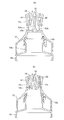
- FIG. 1 is a longitudinal explanatory view of a liquid dispensing container in which a push-pull cap according to an embodiment of the present invention is fitted to a container, where (a) is when opened and (b) is when closed. (A) is explanatory drawing of the opening area and liquid flow path area which the longitudinal direction of the push pull cap was, and (b) is sectional drawing of a liquid flow path part.
- FIG. 1 is an explanatory view of a dispensing container provided with a push-pull cap according to an embodiment of the present invention, wherein (a) shows an open state and (b) shows a closed state.
- the push-pull cap according to the embodiment is attached to a container (bottle) 10 and dispenses contents by squeezing the container 10.
- the container 10 may be blow molded or resin molded, and may have any structure that can be elastically deformed and elastically restored when pressed or not pressed.
- the push-pull cap is mounted in a liquid-tight manner by a cap main body 12 screwed from the outside to the small-diameter mouth portion 10a at the upper end of the container 10 and a rod-shaped plug body 12c erected on the cap main body 12 to move up and down. With an overcap 14 enabled.
- the overcap 14 has a spout 18 for pouring liquid into the top portion 16 and a cylindrical portion 20 that surrounds the spout 18 and hangs down to the container 10 side. (Internal shape) gradually expands downward from the spout 18.
- the cap body 12 is a generally rotating body that communicates vertically, and the lower portion 12a spreads in a bowl shape to cover the shoulder portion of the container 10, and a female thread is formed in the cylindrical portion inside thereof to form the container 10 Screwed into the mouth portion 10a.
- a cylindrical receiving portion 12b extends upward at the upper portion, and a cylindrical portion 20 inside the overcap 14 is inserted into the inner periphery of the cylindrical receiving portion 12b.
- the cap body 12 is provided with a rod-shaped plug body 12c extending upward at an axial center position surrounded by the cylindrical portion 20.
- a partition wall is formed between the lower portion 12a and the cylindrical receiving portion 12b, and the cylindrical receiving portion 12b and the rod-shaped plug body 12c are provided concentrically on the partition wall, and the rod-shaped plug body.
- a circulation hole 12d penetrating the partition wall is formed adjacent to 12c.
- the outer cap 14 is formed in the overcap 14 so as to surround the tubular portion 20 and to be continuous with the top portion 16 with a gap between them.
- the overcap 14 is attached to the cap body 12 and assembled so that the cylindrical receiving portion 12b is positioned in the gap.
- the tubular portion 20 is located inside the tubular receiving portion 12b, and the outer wall portion 14a is provided so as to cover the outer periphery on the outside.
- convex portions are formed on the inner surface of the outer wall portion 14a and the outer surface of the cylindrical receiving portion 12b so that the overcap 14 can be locked and fixed at the open / closed position.
- the short portion outward from the spout 18 expands in a trumpet shape, but the narrowest portion of the spout 18 located on the inner side from the top portion 16 is narrowed.
- the opening flows out (opening area S 1 shown in FIG. 2A).
- the cap body 12 has a structure in which a rod-like plug body 12c extends upward at an axial center position surrounded by the cylindrical portion 20. The rod-shaped plug 12c is pulled out and inserted into the spout 18 (the overcap 14 is moved up and down), and the spout 18 is opened and closed.
- the opening area of the spout 18 is S 1
- the cap main body 12 is overloaded at the distal end side of the rod-shaped plug 12 c. 1 ⁇ (S 2 / S 1 ) ⁇ 2, where S 2 is the liquid flow path area between the tip of the fitting portion with the cap 14 and the inner wall surface of the cylindrical portion 20.
- the liquid flow path area S 2 is required to be the opening area S 1 and equal to or more.
- the opening area S 1 and the liquid flow area of the overcap 14 the relationship between S 2, by a 1 ⁇ (S 2 / S 1 ) ⁇ 2, remaining in the spout 18 of the overcap 14 content
- the size can be set so that the liquid can be easily pulled back and the liquid can be easily discharged even when the liquid is discharged.
- the internal shape of the cylindrical portion 20 inside the overcap 14 has a conical shape that gradually expands downward from the spout.
- the internal shape of the cylindrical portion 20 of the overcap 14 is a shape that gradually expands, the pulled back content liquid is transmitted to the wall surface and has an effect of easily returning inward.
- the conical shape gradually expanding may be a domed shape having a circular arc which is convex inward or outward to the extent that can be regarded in a conical shape, the liquid flow path area S 2 and the relationship of the opening area S 1 As long as it can be secured.
- the overcap 14 is moved upward to open the spout 18.
- Spout 18 the inner surface located on both ends of the arrows indicate the opening area S 1 of the cap, when closed overcap 14, a sealing position in contact with the rod-shaped stopper 12c.
- both side ends of the arrows showing the liquid flow path area S 2 is located slightly below the upper end of the rod-shaped stopper 12c (tip), the outer periphery of the rod-shaped stopper 12c corresponding to the arrows indicating the S 2
- the position of the surface is a seal position where the outer peripheral surface of the rod-shaped plug body 12c contacts the inner surface of the spout 18 when the overcap 14 moves downward and closes.
- the sealing position is positioned slightly below the upper end of the rod-shaped plug body 12c so that the upper end of the rod-shaped plug body 12c projects beyond the spout 18 when the overcap 14 is closed. It is a thing. Therefore, with the structure in which the rod-shaped plug body 12c is protruded, the spout 18 and the rod-shaped plug body 12c are brought into contact with each other at the positions indicated by the arrows S 1 and S 2 , so that sealing can be ensured and liquid leakage can be prevented.
- the overcap 14 has the spout 18 for pouring the liquid into the top portion 16 and has the cylindrical portion 20 that surrounds the spout 18 and hangs down to the container side.
- the inner wall below the spout 18 is formed in a gradually expanded shape (particularly a conical shape) from the spout 18 without providing a step or a bending point. This makes it difficult to stay in place and can be efficiently dropped into the cap.
- it is the “liquid remaining inside the spout” that has the greatest influence on the occurrence of bubble jumping, so the inner wall of the cylindrical portion 20 is not provided with steps or bending points, and gradually. It can be effectively dealt with by expanding the shape.
- bottles that tend to have less volume change before and after squeezing, for example, bottles having a square cross-sectional shape.
- the push-pull cap of the present invention can be used for liquid dispensing container products that contain liquid detergents, liquid softeners, and the like.
Landscapes
- Engineering & Computer Science (AREA)
- Mechanical Engineering (AREA)
- Closures For Containers (AREA)
Abstract
本発明は、液を排出後に注出口付近に溜まっている液を、更に効率的にボトル内部に戻す機構を実現するプッシュプルキャップを提供する。 本発明は、容器(10)に装着されて、容器をスクイズすることによって内容物を注出するプッシュプルキャップであって、キャップ本体(12)と、キャップ本体(12)に立設された棒状栓体(12c)で液密に装着されて上下動可能とされたオーバーキャップ(14)を有し、このオーバーキャップ(14)が、天部(16)に液体を注出する注出口(18)を有すると共に注出口(18)を囲んで容器(10)側に垂下する筒状部(20)を有し、この筒状部(20)の内部形状が注出口(18)から下方に向けて漸次拡開するものである。
Description
本発明は、オーバーキャップを押し引きして開閉するプッシュプルキャップ及びそれを備えた液体注出容器に関する。
成形されたプラスチックボトルの中には、プッシュプルキャップと呼ばれるキャップが装着されたものがあり、このプッシュプルキャップは、押し込む(プッシュ)操作と引っ張る(プル)操作によってキャップの注出口を開閉することが可能となっている(特許文献1参照)。
一般に、開閉するプッシュプルキャップにおいて、容器胴部を把持した際等に、前回使用時に注出口付近に残った液による泡飛びや液飛びを防止することが種々に考えられているが、更に十分さが求められている。
例えば、プッシュプルキャップ以外のキャップの液戻し構造に関して、特許文献2には注出口に一体の密閉部材を使用時に取り去る液体洗浄剤製品が開示されている。この特許文献2に記載の液体洗浄剤製品では、キャップの天井部に注出口が形成されると共に、キャップの内部側には、注出口の開口部周辺に、注出口内面に延長させるか注出口に近接させて開口を囲む遮蔽壁が設けられている。そして、遮蔽壁の容器側開口に傾斜部を形成しており、この傾斜部を液がつたうことで、液戻し促進を図っている。
しかしながら、この特許文献2記載のキャップの機構を、プッシュプルキャップに採用した場合、容器口元内に挿入する遮蔽壁が寸法を要するのでオーバーキャップの外径が大きくなってしまい、デザイン上の制約や、樹脂量増加などが問題となる。
一方、プッシュプルキャップに関する特許文献3では、筒状部の内壁に非対称形状の段差の設置により、液戻しを促進している。
しかしながら、ボトル胴部スクイズによる内容液排出後のボトル復元体積が小さい場合や、又は、内容液の粘度が高い場合に、上記特許文献等の既存の抑制機構では、液の戻りが不十分であり、泡飛びが発生してしまうことが確認された。
本発明は、斯かる実情に鑑み、液を排出後に注出口付近に溜まっている液を、更に効率的にボトル内部に戻す機構を実現するプッシュプルキャップを提供するものである。
本発明は、容器(ボトル)に装着されて、容器をスクイズすることによって内容物を注出するプッシュプルキャップであって、キャップ本体と、キャップ本体に立設された棒状栓体でキャップ本体に液密に装着され、上下動可能とされたオーバーキャップを有し、このオーバーキャップが、天部に液体を注出する注出口を有すると共に注出口を囲んで容器側に垂下する筒状部を有し、この筒状部の内部形状が注出口から下方に向けて漸次拡開することを特徴とするプッシュプルキャップである。
本発明においては、上記オーバーキャップを上方へ稼動させた開口時に、注出口の開口面積をS1とし、キャップ本体の棒状栓体先端側におけるオーバーキャップとの嵌合部の先端部における液流路面積をS2としたときに、1≦(S2/S1)≦2であることが好適である。
本発明においては、上記オーバーキャップ内部の筒状部の内部形状が、注出口から下方に向けて漸次拡開する円錐形状を有することが好適である。
発明者の知見によれば、泡飛び発生に最も影響するのは、「注出口内部に残留した液」である。
本発明のプッシュプルキャップによれば、オーバーキャップが、天部に液体を注出する注出口を有すると共に注出口を囲んで容器側に垂下する筒状部を有し、この筒状部の内部形状が注出口から下方に向けて漸次拡開しており、液が局所的に留まりづらくなり、内容液の排出後に容器が復元する際に、キャップ内部へスムーズに引き込まれ、効率的に落とすことができる。
したがって、内容液の排出後に容器の復元力・復元体積が小さい場合(角形ボトル等)や、内容液の粘度が高い場合、既存の抑制機構では、液の戻りが不十分である場合も、注出口付近の残液もキャップ内に効率的に落とすことができる。
なお、筒状部において注出口から下の内壁の内部形状を、段差や屈曲点を設けず、漸次拡開した形状、特に、円錐形状にすることで、一層溜まりにくくすることができる。
以下、本発明の実施形態について添付図面を参照して説明する。
図1は、本発明の実施形態に係るプッシュプルキャップを設けた注出用容器の説明図で、(a)が開口時、(b)が閉口時をそれぞれ示す。
実施形態に係るプッシュプルキャップは、容器(ボトル)10に装着されて、容器10をスクイズすることによって内容物を注出するものである。なお、容器10はブロー成型や樹脂成型したものであり、押圧・非押圧したときに弾性変形・弾性復帰する構造のものであればよい。
プッシュプルキャップは、容器10の上端に細径の口元部10aに外側からネジ結合しているキャップ本体12と、キャップ本体12に立設された棒状栓体12cで液密に装着されて上下動可能とされたオーバーキャップ14とを有する。
このオーバーキャップ14は、天部16に液体を注出する注出口18を有すると共に注出口18を囲んで容器10側に垂下する筒状部20を有し、この筒状部20の内周(内部形状)が注出口18から下方に向けて漸次拡開する。
詳しくは、キャップ本体12は、上下に連通された概略回転体であり、下部12aが袴状に広がって容器10の肩部を覆い、その内部に筒状部に雌ねじが形成されて容器10の口元部10aに螺合している。上部に筒状受け部12bが上方向きに延在し、筒状受け部12bの内周に、オーバーキャップ14の内側の筒状部20が挿入されている。また、キャップ本体12には、筒状部20に取り囲まれた軸心位置に棒状栓体12cが上方に延在して立設している。キャップ本体12では、下部12aと筒状受け部12bとの間に仕切り壁が形成され、その仕切り壁には同心状に筒状受け部12bと棒状栓体12cが立設すると共に、棒状栓体12cに隣接して仕切り壁を貫通する流通孔12dが形成されている。
オーバーキャップ14には、筒状部20を取り囲んで外壁部14aが互いの間に隙間を置いて天部16で連続されて形成されている。この隙間内に筒状受け部12bが位置するようにオーバーキャップ14をキャップ本体12に装着して組み付ける。この状態で、該筒状受け部12bの内側に筒状部20が位置し、外側で外周を覆うように前記外壁部14aが設けられる。また、この外壁部14aの内面と筒状受け部12bの外面に互いに凸部が形成されて、オーバーキャップ14の開・閉位置で係止して位置固定可能に形成されている。
オーバーキャップ14の天部16では、注出口18から外向きの短い部分ではラッパ状に拡径するが、天部16から内側に位置したところの絞り込まれるような最も狭い箇所が注出口18の液流出する開口(図2(a)に示す開口面積S1)になる。また、キャップ本体12には、筒状部20に取り囲まれた軸心位置に棒状栓体12cが上方に延在している構造になっている。この注出口18に前記棒状栓体12cが抜・挿して(オーバーキャップ14が上・下して)注出口18が開・閉する。
つまり、図1(a)に示すように、当該オーバーキャップ14を上方に移動させたときに棒状栓体12cが注出口18から離れて開状態(開位置)になる。
一方、図1(b)に示すように、当該オーバーキャップ14を下方に移動させたときに棒状栓体12cが注出口18に入り込んで密着して閉状態(閉位置)になる。
ここで、図2に示すように、上記オーバーキャップ14を上方へ稼動させた注出口18の開口時に、注出口18の開口面積をS1とし、キャップ本体12の棒状栓体12c先端側におけるオーバーキャップ14との嵌合部の先端部と、筒状部20内壁面との間における液流路面積をS2としたときに、1≦(S2/S1)≦2としている。
1≦(S2/S1)≦2とする根拠を説明する。
(S2/S1)<1の場合、内容液の排出後に容器が復元する際に、液流路面積S2部分の空気の流速が開口面積S1部分よりも大きいために、オーバーキャップ14の注出口18に残存した内容液がキャップ本体12側に引き戻され易いが、液排出時にS2部分での抵抗が高まり、スムーズな排出を行いづらいという問題がある。
2<(S2/S1)の場合、液流路面積S2部分の空気の流速が開口面積S1部分よりも小さくなり過ぎて、オーバーキャップ14の注出口18に残存した内容液をキャップ本体12側に引き戻す効果が弱くなる。
以上から、オーバーキャップ14の開口面積S1と液流路面積S2との関係について、スクイズ後に容器10が復元する際に、キャップ注出口18から空気が取り込まれるが、液流路面積S2を開口面積S1の2倍以内とすることで、空気が通過する流速が早くなるため、内容液が注出口下部に留まりづらくなる。一方、液流路面積S2が小さ過ぎると、スムーズな排出を行いづらく、押し出しづらくなってしまうので、液流路面積S2は開口面積S1と同等以上である必要がある。したがって、オーバーキャップ14の開口面積S1と液流路面積をS2との関係を、1≦(S2/S1)≦2とすることによって、オーバーキャップ14の注出口18に残存した内容液を引き戻し易く、かつ液排出時にも液を出し易くすることができる寸法範囲にできる。
また、上記オーバーキャップ14内部の筒状部20の内部形状が、注出口から下方に向けて漸次拡開する円錐形状を有している。
したがって、オーバーキャップ14の筒状部20の内部形状が漸次拡開する形状であるために、引き戻された内容液が壁面に伝わって内方に戻り易くなる効果を有する。
この場合、筒状部20の内部形状は、ドーム状よりも、円錐形状であることで、液流路面積S2を開口面積S1の2倍以内とし易い。なお、漸次拡開する円錐形状とは、円錐形状に見なせる程度の内方又は外方に向けて凸となる円弧を持つドーム状形状でもよく、液流路面積S2及び開口面積S1の関係を確保できればよい。
なお、図2(a)において、オーバーキャップ14を上方に移動させて注出口18を開口している状態である。キャップの開口面積S1を示す矢印の両側端部に位置する注出口18内面が、オーバーキャップ14を閉じた際に、棒状栓体12cが接するシール位置である。また、液流路面積S2を示す矢印の両側端が棒状栓体12cの上端(先端)よりもやや下方に位置しているが、当該S2を示す矢印に対応する棒状栓体12cの外周面の位置が、オーバーキャップ14が下方に移動して閉じた際に、棒状栓体12cの外周面が注出口18の内面に接するシール位置である。
このようにシール位置を、前記棒状栓体12cの上端よりもやや下方に位置させるのは、オーバーキャップ14が閉じた際に、前記棒状栓体12cの上端が注出口18よりも突出するようにしたものである。
したがって、この棒状栓体12cを突出させる構造により、注出口18と棒状栓体12cの互いが、矢印S1、S2で示す位置ですり合ってシールが確実にでき、液漏れが防止できる。
このようにシール位置を、前記棒状栓体12cの上端よりもやや下方に位置させるのは、オーバーキャップ14が閉じた際に、前記棒状栓体12cの上端が注出口18よりも突出するようにしたものである。
したがって、この棒状栓体12cを突出させる構造により、注出口18と棒状栓体12cの互いが、矢印S1、S2で示す位置ですり合ってシールが確実にでき、液漏れが防止できる。
実施形態のプッシュプルキャップによれば、オーバーキャップ14が、天部16に液体を注出する注出口18を有すると共に注出口18を囲んで容器側に垂下する筒状部20を有し、この筒状部20において、注出口18から下方に向けて、注出口18から下の内壁を、段差や屈曲点を設けず、漸次拡開した形状(特に円錐形状)にすることで、液が局所的に留まりづらくなり、キャップ内部へ効率的に落とすことができる。発明者の知見によれば、泡飛び発生に最も影響するのは、「注出口内部に残留した液」であるので、上記の筒状部20の内壁を、段差や屈曲点を設けず、漸次拡開した形状にすることで効果的に対処できる。
特に、スクイズ前後の体積変化が少なくなり易いボトル、例えば角型の断面形状を有するボトルで威力を発揮する。
ここで、本発明品と比較品とについて液戻り泡飛びを比較した結果を下記する。

上記から、1≦(S2/S1)≦2の範囲内で好適な本発明品は10秒という短い時間で液戻りが良好にでき、泡飛びが発生しないことが確認された。これに対して、比較品2では、泡飛びが無かったが、液戻りに30秒を要することが確認された。また、比較品l、3、4はいずれも30秒の静止でも液戻りが不十分であって、泡飛びが発生することが確認された。これらから、1≦(S2/S1)≦2であることが好ましく、本発明品の有用性が明確になった。
本発明のプッシュプルキャップは、液体洗剤、液体柔軟剤等を収容する液体注出容器製品に利用することができる。
10 容器
12 キャップ本体
12a 下部
12b 筒状受け部
12c 棒状栓体
14 オーバーキャップ
14a 外壁部
16 天部
18 注出口
20 筒状部
12 キャップ本体
12a 下部
12b 筒状受け部
12c 棒状栓体
14 オーバーキャップ
14a 外壁部
16 天部
18 注出口
20 筒状部
Claims (3)
- 容器に装着されて、容器をスクイズすることによって内容物を注出するプッシュプルキャップであって、
キャップ本体と、キャップ本体に立設された棒状栓体で液密に装着され、上下動可能とされたオーバーキャップを有し、
このオーバーキャップが、天部に液体を注出する注出口を有すると共に注出口を囲んで容器側に垂下する筒状部を有し、この筒状部の内部形状が注出口から下方に向けて漸次拡開することを特徴とするプッシュプルキャップ。 - 前記オーバーキャップを上方へ稼動させた開口時に、
注出口の開口面積をS1とし、キャップ本体の棒状栓体先端側におけるオーバーキャップとの嵌合部の先端部における液流路面積をS2としたときに、
1≦(S2/S1)≦2であることを特徴とする請求項1に記載のプッシュプルキャップ。 - 前記オーバーキャップ内部の筒状部の内部形状が、注出口から下方に向けて漸次拡開する円錐形状を有することを特徴とする請求項1又は2に記載のプッシュプルキャップ。
Priority Applications (1)
| Application Number | Priority Date | Filing Date | Title |
|---|---|---|---|
| JP2016513797A JP6774872B2 (ja) | 2014-04-15 | 2015-04-14 | プッシュプルキャップ |
Applications Claiming Priority (2)
| Application Number | Priority Date | Filing Date | Title |
|---|---|---|---|
| JP2014083728 | 2014-04-15 | ||
| JP2014-083728 | 2014-04-15 |
Publications (1)
| Publication Number | Publication Date |
|---|---|
| WO2015159888A1 true WO2015159888A1 (ja) | 2015-10-22 |
Family
ID=54324093
Family Applications (1)
| Application Number | Title | Priority Date | Filing Date |
|---|---|---|---|
| PCT/JP2015/061490 Ceased WO2015159888A1 (ja) | 2014-04-15 | 2015-04-14 | プッシュプルキャップ |
Country Status (2)
| Country | Link |
|---|---|
| JP (1) | JP6774872B2 (ja) |
| WO (1) | WO2015159888A1 (ja) |
Cited By (1)
| Publication number | Priority date | Publication date | Assignee | Title |
|---|---|---|---|---|
| WO2017187684A1 (ja) * | 2016-04-30 | 2017-11-02 | 洪 瑟芬 | 注出ノズル開閉機構 |
Citations (7)
| Publication number | Priority date | Publication date | Assignee | Title |
|---|---|---|---|---|
| US3201013A (en) * | 1963-12-11 | 1965-08-17 | Product Design & Engineering I | Dispensing and closure cap for containers |
| JPH072441Y2 (ja) * | 1990-03-02 | 1995-01-25 | 東洋製罐株式会社 | 注出蓋 |
| EP0854094A1 (en) * | 1996-11-27 | 1998-07-22 | Kerrin Maurice Lyons | Container provided with a valve closure |
| JP2001130616A (ja) * | 1999-11-05 | 2001-05-15 | Lion Corp | プッシュプルキャップ |
| JP2001151260A (ja) * | 1999-11-30 | 2001-06-05 | Yoshino Kogyosho Co Ltd | 容器の注出キャップ |
| JP2004051138A (ja) * | 2002-07-18 | 2004-02-19 | Yoshino Kogyosho Co Ltd | プッシュプルキャップ |
| JP2004284619A (ja) * | 2003-03-20 | 2004-10-14 | Mikasa Sangyo Kk | プッシュプル注出キャップ |
Family Cites Families (2)
| Publication number | Priority date | Publication date | Assignee | Title |
|---|---|---|---|---|
| JPH0589255U (ja) * | 1992-05-22 | 1993-12-07 | 凸版印刷株式会社 | 泡状注出キャップ |
| JP2002264958A (ja) * | 2001-03-12 | 2002-09-18 | Lion Corp | 液体洗浄剤製品 |
-
2015
- 2015-04-14 WO PCT/JP2015/061490 patent/WO2015159888A1/ja not_active Ceased
- 2015-04-14 JP JP2016513797A patent/JP6774872B2/ja active Active
Patent Citations (7)
| Publication number | Priority date | Publication date | Assignee | Title |
|---|---|---|---|---|
| US3201013A (en) * | 1963-12-11 | 1965-08-17 | Product Design & Engineering I | Dispensing and closure cap for containers |
| JPH072441Y2 (ja) * | 1990-03-02 | 1995-01-25 | 東洋製罐株式会社 | 注出蓋 |
| EP0854094A1 (en) * | 1996-11-27 | 1998-07-22 | Kerrin Maurice Lyons | Container provided with a valve closure |
| JP2001130616A (ja) * | 1999-11-05 | 2001-05-15 | Lion Corp | プッシュプルキャップ |
| JP2001151260A (ja) * | 1999-11-30 | 2001-06-05 | Yoshino Kogyosho Co Ltd | 容器の注出キャップ |
| JP2004051138A (ja) * | 2002-07-18 | 2004-02-19 | Yoshino Kogyosho Co Ltd | プッシュプルキャップ |
| JP2004284619A (ja) * | 2003-03-20 | 2004-10-14 | Mikasa Sangyo Kk | プッシュプル注出キャップ |
Cited By (1)
| Publication number | Priority date | Publication date | Assignee | Title |
|---|---|---|---|---|
| WO2017187684A1 (ja) * | 2016-04-30 | 2017-11-02 | 洪 瑟芬 | 注出ノズル開閉機構 |
Also Published As
| Publication number | Publication date |
|---|---|
| JP6774872B2 (ja) | 2020-10-28 |
| JPWO2015159888A1 (ja) | 2017-04-13 |
Similar Documents
| Publication | Publication Date | Title |
|---|---|---|
| JP5523899B2 (ja) | 詰替え用ノズル | |
| CN101233052B (zh) | 容器封闭组件及其与具有带外螺纹颈部的容器组合物 | |
| US20140144949A1 (en) | Delayed flow baffled dispensing closure | |
| CN110869288A (zh) | 塑料盖及其制造方法 | |
| JP5427542B2 (ja) | スクイズ容器用キャップ | |
| EP2899135A1 (en) | Device for pouring liquid contained in a container | |
| WO2015159888A1 (ja) | プッシュプルキャップ | |
| JP5489703B2 (ja) | 詰め替え容器 | |
| JP5489755B2 (ja) | 注出キャップ | |
| JP5512421B2 (ja) | 容器の注出キャップ | |
| JP5415342B2 (ja) | 詰替え用受液栓 | |
| JP5611543B2 (ja) | 液だまり防止キャップ | |
| JP2015214348A (ja) | キャップおよびその製造方法 | |
| JP5384244B2 (ja) | ブロー成形容器 | |
| JP2015205710A (ja) | プッシュプルキャップ | |
| JP5977535B2 (ja) | 注出キャップ | |
| JP5929188B2 (ja) | 栓付き注出ノズル | |
| JP2009286465A (ja) | ヒンジキャップ | |
| JP5754982B2 (ja) | 超軽量ヒンジキャップ | |
| JP6325311B2 (ja) | 注出容器 | |
| CN203359096U (zh) | 带有喷嘴帽的容器 | |
| JP5468937B2 (ja) | 液体容器の注出具 | |
| JP5384243B2 (ja) | ブロー成形容器 | |
| JP5995531B2 (ja) | 抜栓式キャップ | |
| JP2024148340A (ja) | スクイーズ容器 |
Legal Events
| Date | Code | Title | Description |
|---|---|---|---|
| 121 | Ep: the epo has been informed by wipo that ep was designated in this application |
Ref document number: 15780247 Country of ref document: EP Kind code of ref document: A1 |
|
| ENP | Entry into the national phase |
Ref document number: 2016513797 Country of ref document: JP Kind code of ref document: A |
|
| NENP | Non-entry into the national phase |
Ref country code: DE |
|
| 122 | Ep: pct application non-entry in european phase |
Ref document number: 15780247 Country of ref document: EP Kind code of ref document: A1 |