WO2015156046A1 - 内視鏡 - Google Patents
内視鏡 Download PDFInfo
- Publication number
- WO2015156046A1 WO2015156046A1 PCT/JP2015/055421 JP2015055421W WO2015156046A1 WO 2015156046 A1 WO2015156046 A1 WO 2015156046A1 JP 2015055421 W JP2015055421 W JP 2015055421W WO 2015156046 A1 WO2015156046 A1 WO 2015156046A1
- Authority
- WO
- WIPO (PCT)
- Prior art keywords
- bending
- lever
- switching
- semi
- force
- Prior art date
Links
Images


Classifications
-
- G—PHYSICS
- G02—OPTICS
- G02B—OPTICAL ELEMENTS, SYSTEMS OR APPARATUS
- G02B23/00—Telescopes, e.g. binoculars; Periscopes; Instruments for viewing the inside of hollow bodies; Viewfinders; Optical aiming or sighting devices
- G02B23/24—Instruments or systems for viewing the inside of hollow bodies, e.g. fibrescopes
- G02B23/2476—Non-optical details, e.g. housings, mountings, supports
-
- A—HUMAN NECESSITIES
- A61—MEDICAL OR VETERINARY SCIENCE; HYGIENE
- A61B—DIAGNOSIS; SURGERY; IDENTIFICATION
- A61B1/00—Instruments for performing medical examinations of the interior of cavities or tubes of the body by visual or photographical inspection, e.g. endoscopes; Illuminating arrangements therefor
- A61B1/005—Flexible endoscopes
- A61B1/0051—Flexible endoscopes with controlled bending of insertion part
- A61B1/0057—Constructional details of force transmission elements, e.g. control wires
-
- G—PHYSICS
- G01—MEASURING; TESTING
- G01D—MEASURING NOT SPECIALLY ADAPTED FOR A SPECIFIC VARIABLE; ARRANGEMENTS FOR MEASURING TWO OR MORE VARIABLES NOT COVERED IN A SINGLE OTHER SUBCLASS; TARIFF METERING APPARATUS; MEASURING OR TESTING NOT OTHERWISE PROVIDED FOR
- G01D11/00—Component parts of measuring arrangements not specially adapted for a specific variable
- G01D11/16—Elements for restraining, or preventing the movement of, parts, e.g. for zeroising
-
- A—HUMAN NECESSITIES
- A61—MEDICAL OR VETERINARY SCIENCE; HYGIENE
- A61B—DIAGNOSIS; SURGERY; IDENTIFICATION
- A61B1/00—Instruments for performing medical examinations of the interior of cavities or tubes of the body by visual or photographical inspection, e.g. endoscopes; Illuminating arrangements therefor
- A61B1/00064—Constructional details of the endoscope body
- A61B1/00071—Insertion part of the endoscope body
- A61B1/0008—Insertion part of the endoscope body characterised by distal tip features
- A61B1/00098—Deflecting means for inserted tools
-
- F—MECHANICAL ENGINEERING; LIGHTING; HEATING; WEAPONS; BLASTING
- F16—ENGINEERING ELEMENTS AND UNITS; GENERAL MEASURES FOR PRODUCING AND MAINTAINING EFFECTIVE FUNCTIONING OF MACHINES OR INSTALLATIONS; THERMAL INSULATION IN GENERAL
- F16L—PIPES; JOINTS OR FITTINGS FOR PIPES; SUPPORTS FOR PIPES, CABLES OR PROTECTIVE TUBING; MEANS FOR THERMAL INSULATION IN GENERAL
- F16L55/00—Devices or appurtenances for use in, or in connection with, pipes or pipe systems
- F16L55/26—Pigs or moles, i.e. devices movable in a pipe or conduit with or without self-contained propulsion means
- F16L55/28—Constructional aspects
- F16L55/40—Constructional aspects of the body
Definitions
- the present invention relates to an endoscope that has a bending portion on the distal end side of an insertion portion and performs a bending operation of the bending portion by a bending operation member provided in an operation portion on the proximal side.
- endoscopes are used in the medical field and the industrial field.
- Some endoscopes have a curved portion provided on the distal end side of an elongated insertion portion.
- the bending portion is configured to bend in a desired direction by manually operating a bending operation member provided in an operation portion on the proximal end side of the insertion portion.
- a bending operation member a bending knob or bending lever that is rotated around an axis, a joystick lever that is tilted, and the like are provided in the operation unit.
- the curved portion provided in the insertion portion is covered with a curved rubber having elasticity.
- a plurality of endoscope built-in items such as a treatment instrument channel tube, an air supply tube, a water supply tube, a signal cable in which a plurality of signal lines are gathered, and a light guide for illumination are inserted and arranged in the insertion portion.
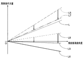
- These built-in endoscopes provide elastic resistance when the bending portion is bent. Therefore, when the bending portion is bent, the bending portion to be bent has an elastic restoring force (see a solid line L in FIG. 1) for returning the bending portion to a linear state by the bending rubber and the built-in endoscope. work.
- the bending portion resistance force obtained by combining these elastic restoring force and friction force increases as the bending angle of the bending portion increases.
- the user when the bending portion is bent, the user operates the bending operation member with the bending operation force amount indicated by the first broken line L1 in FIG. 1 which is an amount of force that resists the bending portion resistance force.
- the bending portion resistance increases as the bending angle of the bending portion increases, and the amount of bending operation force for operating the bending operation member also increases.
- a conventional endoscope operation portion was provided with a semi-fixed mechanism composed of, for example, a lever, a cam mechanism, and a friction plate.
- the semi-fixed mechanism is a mechanism that switches between a semi-fixed state in which the friction plate is brought into contact with, for example, a drum in which one end of the bending wire is fixed and a semi-fixed released state in which the friction plate is separated from the drum in accordance with a lever operation.
- the bending portion In the semi-fixed state, the bending portion can be bent in accordance with the operation of the bending operation member, while maintaining the bending state before the release when the user releases the finger from the bending operation member. For this reason, when the user grasps the target observation site, the user selects the semi-fixed state to perform observation or the like while preventing the observation site from being lost.
- the bending operation force amount for operating the bending operation member includes the first bending operation force amount indicated by the first broken line L1 that increases the bending angle of the bending portion, and the second broken line that maintains the bending angle in this state. Unlike the bending holding force amount indicated by 2, the bending holding force amount is smaller than the elastic restoring force.
- a semi-fixing force (FIG. The force F) having the magnitude indicated by the arrow may be applied from the semi-fixed mechanism to the drum.
- the bending operation force amount in the semi-fixed state is obtained by adding the semi-fixing force (force F) to the first bending operation force amount.
- force F the semi-fixing force
- This is the second bending operation force amount indicated by the added two-dot chain line L3. That is, in an endoscope provided with a semi-fixed mechanism, the risk when the user removes the finger from the bending operation member is eliminated, while the burden on the finger during the bending operation in the semi-fixed state is further increased.
- the present invention has been made in view of the above circumstances, and the bending portion can be switched between a semi-fixed state and a semi-fixed release state, and has excellent operability while reducing the bending operation force when bending the bending portion.
- the purpose is to provide an endoscope.
- An endoscope includes an insertion portion that is inserted into a portion to be observed and includes a bending portion that can be bent in at least two directions with respect to the insertion axis direction, and the proximal end side of the insertion portion.
- the oscillating portion is pivoted about a fulcrum provided in the operating portion, the distal end of which is connected to the bending portion, the traction member that bends the bending portion by traction, and the base end of the traction member is connected.
- a bending operation member that is movably provided and applies a traction force to the traction member by swinging; a first end portion; and a second end portion, wherein the first end portion is more than the fulcrum.
- An operation force amount reducing unit having an elastic member that is swingably connected to the bending operation member on the insertion portion side and that can press the bending operation member via the first end, and the elastic member that performs the bending operation
- a switching operation member that switches between a pressing state for pressing the member and a non-pressing state. It is.
- FIGS. 6A and 6B are diagrams illustrating another configuration example of the semi-fixed mechanism switching operation member, and are diagrams illustrating a semi-fixed state of the semi-fixed mechanism switching operation member.
- release state of a semi-fixation mechanism switching operation member The figure explaining the mechanism which adjusts the assist force of the operation force amount reduction
- the endoscope 1 includes a long insertion portion 2, an operation portion 3 connected to the proximal end of the insertion portion 2, and a universal cord 4 extending from the operation portion 3. Configured.
- An end of the universal cord 4 is provided with an endoscope connector (not shown) that is connected to a light source device (not shown) that is an external device.
- the insertion portion 2 is a portion to be inserted into an observed portion such as a body, and is provided with a distal end portion 2a, a bending portion 2b, and a rigid tube portion 2c in order from the distal end side.
- the tip 2a is made of a hard member such as stainless steel.
- the bending portion 2b is configured to bend in, for example, four directions of up, down, left and right with respect to the insertion axis direction.
- the rigid tube portion 2c is formed of a metal tube member such as stainless steel.
- the bending portion 2b only needs to be able to bend in at least two directions with respect to the insertion axis direction.
- the configuration in which the bending portion 2b is bent in four directions, up, down, left, and right the configuration in which the bending portion 2b is bent in the up and down direction and the configuration in which it is bent in the left and right direction are substantially the same. For this reason, the structure which curves in an up-down direction is mainly demonstrated.
- the bending portion 2b is mainly configured by providing a bending piece set (not shown) and a bending rubber 2g.
- the bending piece set is configured to bend up, down, left and right by rotatably connecting a plurality of bending pieces (not shown).
- the curved rubber 2g is an outer skin having a predetermined elastic force and covers the outer periphery of the curved piece set.
- the elastic force of the bending rubber 2g acts as a resistance force when the bending portion 2b is bent, and when the bending portion 2b is bent, it acts as a restoring force for returning the bending portion 2b to a linear state.
- the insertion portion 2 is a so-called rigid insertion portion in which the distal end portion 2a, the bending portion 2b, and the rigid tube portion 2c are connected.
- the insertion portion 2 is not limited to a rigid insertion portion, and may be a soft insertion portion in which a distal end portion 2a, a bending portion 2b, and a flexible tube portion 2d having flexibility are connected.
- a treatment instrument channel tube or the like may be inserted into the insertion portion 2.
- a rubber boot 7 as an exterior member is provided on the base end side of the operation unit 3.
- the rubber boot 7 is an elastic member having a predetermined elasticity, and includes an elastic holding portion 7a and an elastic fixing portion 7b.
- the elastic holding portion 7 a has a function of elastically holding the angle lever 12, and the elastic fixing portion 7 b has a function of closing the opening 8 m of the frame 8.
- the operation unit 3 is provided with a bending operation member 5 and a semi-fixed mechanism switching operation member 6.
- the bending operation member 5 includes, for example, a joystick type angle lever 12 as a bending operation unit for remotely operating the bending portion 2b.
- the angle lever 12 is provided so as to protrude from the elastic holding part 7 a of the rubber boot 7 constituting the operation part 3.
- the angle lever 12 operates the bending portion 2b while changing the bending angle in any of the four directions of up, down, left and right in accordance with the change of the tilt direction and the change of the tilt angle.
- the semi-fixed mechanism switching operation member 6 includes, for example, a switching lever 31 as a semi-fixed operation unit that performs a switching operation to a semi-fixed state or a semi-fixed release state.
- the switching lever 31 can be switched to a position indicated by a broken line when indicated by a solid line, and the semi-fixing mechanism is set to a semi-fixed release state when the position is a solid line, and is set to a semi-fixed state when the position is a broken line.
- the semi-fixing mechanism enables the bending portion 2b to bend in accordance with the tilting operation of the angle lever 12 in the semi-fixed state, and when the finger is released from the angle lever 12 during the bending operation. It is possible to hold the tilt operation position. That is, the bending portion 2b is in an active bending state that resists the restoring force of the bending rubber 2g when the finger is released from the angle lever 12, and is maintained in the bending state when the finger is released.
- the semi-fixed mechanism in the semi-fixed release state, can, of course, bend the bending portion 2b in accordance with the tilting operation of the angle lever 12, but the finger is released from the angle lever 12 during the bending operation. Sometimes, it becomes impossible to hold the tilting operation position of the angle lever 12. That is, the bending portion 2b changes to a passive bending state when the finger is released from the angle lever 12, and can be bent by a restoring force from the bending rubber 2g, an external force from the outside, or the like.
- the arrangement position of the angle lever 12 and the arrangement position of the switching lever 31 are examples.
- the bending direction of the bending part 2b is made into four directions of up and down, right and left, the bending direction of the bending part 2b is not limited to four directions, The structure which curves in two directions of up and down may be sufficient.
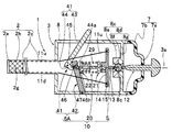
- a frame 8 is disposed on the inner surface of a housing (not shown) which is an exterior member of the operation unit 3 provided on the proximal end side of the insertion unit 2, and a bending operation unit 10 is provided on the frame 8.
- the bending operation unit 10 includes a bending operation member 5, an operation force amount reduction unit 20, and a semi-fixed mechanism switching operation member 6.
- the frame 8 has, for example, a cylindrical shape, and includes an insertion portion arrangement portion 8a provided on the bottom surface 8b side and a bending mechanism attachment portion 8c provided on the opening 8m side.
- the frame 8 has a configuration in which the insertion portion arrangement portion 8a and the bending mechanism attachment portion 8c are integrated, or the insertion portion arrangement portion 8a and the bending mechanism attachment portion 8c are provided on a pipe-shaped frame main body (not shown). It may be integrally formed by screwing, bonding, adhesive, or the like.
- the insertion portion arrangement portion 8a is provided with the base end portion 2r of the insertion portion 2, and the base end portion 2r is integrally fixed to the insertion portion arrangement portion 8a.
- An elastic fixing portion 7b of the rubber boot 7 is fixed in a watertight manner in the opening 8m.
- the bending mechanism attachment portion 8c is composed of an attachment portion main body 8d and a lid portion 8e.
- the attachment portion main body 8d is configured by providing a bending mechanism arrangement portion 8f and a frame fixing portion 8g.
- the frame fixing portion 8g is a disc portion having a predetermined thickness, with one end surface being formed into a flat surface and the bending mechanism disposing portion 8f protruding from the other end surface.
- the outer peripheral surface of the frame fixing portion 8g is an integral surface and is integrally fixed to the inner peripheral surface of the frame 8 by bonding with solder or the like or adhesion with an adhesive.
- the bending mechanism arrangement portion 8f is, for example, a columnar central convex portion protruding at a predetermined height from the center of the other end surface of the frame fixing portion 8g.
- the bending mechanism arrangement portion 8f is provided with a first hemispherical recess 8h1 and a tilt relief hole 8k.
- the first hemispherical recess 8h1 has a circular opening on the end surface of the bending mechanism arrangement portion.
- the tilt relief hole 8k is a tapered central axial direction through hole connecting the first hemispherical recess 8h1 and the outside, and has an opening at the center end face of the frame fixing portion 8g.
- the tilt relief hole 8k has a diameter that continuously increases as it approaches the opening.
- a plurality of through holes having an axis parallel to the central axis may be provided in the frame fixing portion 8g to reduce the weight of the bending mechanism attachment portion 8c.
- the lid portion 8e is a cylindrical body similar to the bending mechanism arrangement portion 8f, and is provided with a second hemispherical concave portion 8h2 and a swing escape hole 8n.
- the second hemispherical recess 8h2 has a circular opening on one end surface.
- the swing escape hole 8n is a tapered central axial direction through hole that connects the second hemispherical recess 8h2 and the outside, and has an opening on the other end surface.
- the swinging relief hole 8n has a diameter that continuously increases as it approaches the opening.
- the lid portion 8e is fixed integrally to the end surface of the bending mechanism arrangement portion 8f, for example, by screw fixing.
- a counterbore hole and a screw escape hole are formed in the lid portion 8e, and a concave portion provided with a female screw is formed in the bending mechanism arrangement portion 8f.
- a sphere (see reference numeral 13) described later is disposed in advance in the first hemispherical concave portion 8h1, and then the lid portion 8e is screw-fixed.
- the sphere 13 is movably disposed in a sphere disposing portion 8q configured by combining the first hemispherical recess 8h1 and the second hemispherical recess 8h2.
- the bending operation member 5 includes an angle lever 12 that applies a traction force to the bending wire 11 that is a traction member, a sphere 13 that is disposed in the sphere disposition portion 8q, and a swing frame 14.
- the spherical body 13 is provided with a lever connecting portion at one end of a shaft passing through the center of the spherical body 13 and with a swing shaft connecting portion at the other end.
- the lever connecting portion and the swing shaft connecting portion are concave portions and are female screw portions.
- the bending wires 11 are an upper bending wire 11u and a lower bending wire 11d.
- the distal end of the upper bending wire 11u is fixed to a predetermined portion of a distal bending piece (not shown) of the bending piece set constituting the bending portion 2b.
- the tip of the lower bending wire 11d is fixed to a predetermined portion of the tip bending piece.
- the proximal end of the upper bending wire 11u and the proximal end of the lower bending wire 11d are fixed to a wire locking member 15 described later.
- the angle lever 12 is a bending operation part, and has, for example, a metal lever main body 12a and, for example, a hemispherical metal finger hook part 12b.
- the finger hook portion 12b is fixed to one end portion of the lever main body 12a protruding from the elastic holding portion 7a of the rubber boot 7.
- the other end portion of the lever main body 12a is a spherical body connecting portion 12c and is provided with a male screw (not shown).
- the male screw of the spherical body connecting portion 12c is screwed into the lever connecting portion of the spherical body 13 provided in the spherical body arranging portion 8q, and is fixed integrally by, for example, adhesion.
- the sphere 13 is movable in the sphere arrangement portion 8q in accordance with the operation of the angle lever 12,
- the swing frame 14 is a connecting shaft 14a, and a cross-shaped frame portion (hereinafter referred to as a cross frame) 14b.
- an operation force amount reducing portion connecting portion 14c is provided to a cross frame 14c.
- the connecting shaft 14a is a central bar portion having a circular cross-sectional shape projecting at a predetermined height from the center of one end surface of the cross frame 14b.
- the operating force amount reducing portion connecting portion 14c is, for example, a cylindrical central convex portion protruding at a predetermined height from the center of the other end surface of the cross frame 14b.
- a male screw (not shown) is provided at the end of the connecting shaft 14a to be screwed into the swing shaft connecting portion of the sphere 13.
- the male screw of the connecting shaft 14a is screwed into the swing shaft connecting portion of the sphere 13 disposed in the sphere mounting portion 8q, and is fixed integrally by, for example, bonding.
- the operating force amount reducing portion connecting portion 14c is provided with a ball connecting portion 14d and a swinging escape hole 14e for movably disposing a first connecting ball portion 23 of the operating force amount reducing portion 20 described later.
- the ball connecting portion 14d includes, for example, a connecting portion hole 14f and a toe member 14g fixed to the connecting portion hole 14f.
- the connecting portion hole 14f is formed with an axis perpendicular to the central axis of the swing frame 14 from the side peripheral surface of the operating force reducing portion connecting portion 14c as a central axis, and the bottom portion is hemispherical.
- the first connecting ball portion 23 of the operating force amount reducing portion 20 is guided to the hemispherical bottom surface through the connecting portion hole 14f.
- the toe member 14g is a rod-shaped member and is integrally fixed to a predetermined position in the connecting portion hole 14f by, for example, adhesion.
- the tip surface of the toe member 14g is formed as a concave spherical surface. That is, the spherical portion connecting portion 14d is configured by combining the hemispheric bottom surface of the connecting portion hole 14f and the concave spherical tip end surface of the toe member 14g.
- the operating force amount reducing portion connecting portion 14c has an opening of a rocking escape hole 14e on an end surface.
- the swinging escape hole 14e is a tapered central axial direction through hole that connects the spherical portion connecting portion 14d and the outside, and the diameter continuously increases as it approaches the opening.
- Reference numeral 14c is a notch groove.
- the notch groove 14c is formed when the first connecting ball portion 23 of the operating force amount reducing unit 20 is arranged from the side perpendicular to the operating portion longitudinal axis 3a toward the hemispherical bottom surface of the connecting portion hole 14f. Twenty first connecting shafts 24a pass through.
- the cross frame 14b has an upper arm 14bu, a lower arm 14bd, a left arm (not shown), and a right arm (not shown).
- the upper arm 14bu, the lower arm 14bd, the left arm, and the right arm are provided so as to protrude radially from the side peripheral surface of the operation force reducing unit connecting portion 14c. The degree interval.
- a wire insertion hole 14h and a locking recess 14k are provided at the end of the upper arm 14bu.
- the wire insertion hole 14h is a through hole in which the upper bending wire 11u is arranged in a loosely fitted state, and has openings on one surface and the other surface of the upper arm 14bu.
- the locking recess 14k is a recess formed on one side of the upper arm 14bu.
- a wire locking portion 15 in which the other end of the upper bending wire 11u is integrally fixed is disposed in the locking recess 14k.
- the central axis of the locking recess 14k and the central axis of the wire insertion hole 14h are coaxial.
- the end of the lower arm 14bd is provided with a wire insertion hole 14h and a locking recess 14k similar to the upper arm 14bu. Accordingly, one surface and the other surface of the lower arm 14bd have an opening of the wire insertion hole 14h.
- a wire locking portion 15 fixed to the lower bending wire 11d is disposed in a recess of the locking recess 14k provided on one surface of the lower arm 14bd.
- the upper bending wire 11u and the lower bending wire 11d are pulled by the swinging frame 14 being swung around the center of the sphere 13 as the angle lever 12 is tilted, and the upper arm 14bu and the lower arm 14bd are tilted. It is configured to be relaxed.
- the operation force amount reduction unit 20 is provided between the bending operation member 5 and the semi-fixed mechanism switching operation member 6.
- the operation force amount reducing unit 20 is a bending operation unit forming unit (hereinafter referred to as a first reducing unit) 21, a semi-fixed mechanism unit forming unit (hereinafter referred to as a second reducing unit) 22, and an elastic member.
- a compression coil spring (hereinafter abbreviated as spring) 29 is provided.
- the first reduction portion 21 is provided with a first connecting ball portion 23 serving as a first end, a first outward flange (hereinafter abbreviated as a first flange) 24, and a sliding shaft 25.
- the first connecting ball portion 23 is a spherical portion and is provided at an end portion of the first connecting shaft 24 a protruding from the first flange 24.
- bowl part 23 is arrange
- the second reduction portion 22 is provided with a cylindrical portion 26, a second outward flange (hereinafter abbreviated as a second flange) 27, and a second connecting ball portion 28 serving as a second end portion.
- the second connecting ball portion 28 is a spherical portion and is provided at an end portion of the second connecting shaft 27 a protruding from the second flange 27.
- the second connecting ball portion 28 is movably disposed in a second ball portion connecting portion 39 described later of the semi-fixed mechanism switching operation member 6 described above.
- the cylinder part 26 protrudes from the one surface of the second flange 27 at a predetermined height, and is provided with a central hole 26h along the central axis of the second reduction part.
- the outer diameter of the cylindrical portion 26 is formed to have a predetermined smaller diameter than the inner diameter of the coil of the spring 29.
- the inner diameter of the central hole 26h is set to a predetermined fit in consideration of the outer diameter of the sliding shaft 25.
- the spring 29 is disposed on the outer peripheral surface of the cylindrical portion 26.
- the spring 29 has a predetermined elastic force, and the natural length is set to a predetermined height.
- the operating force amount reducing unit 20 is configured by inserting the sliding shaft 25 into the central hole 26 h of the cylindrical portion 26 in a state where the spring 29 is disposed on the outer peripheral surface of the cylindrical portion 26. In this configuration, the first reduction part 21 and the second reduction part 22 are movable back and forth along a longitudinal axis connecting the center of the first connection ball part 23 and the center of the second connection ball part 28.
- the center of the second connecting ball portion 28, the center of the first connecting ball portion 23, and the center of the sphere 13 are the length of the operating portion.
- the springs 29 are arranged in a straight line on the shaft 3a and have a natural length.
- one seat of the spring 29 is arranged on the other surface side of the first flange 24, and the other seat of the spring 29 is arranged on one surface side of the second flange 27.
- the one seat and the other seat of the spring 29 may not be in contact with the other surface side of the first flange 24 and the one surface side of the second flange 27, respectively.
- the semi-fixed mechanism switching operation member 6 is mainly configured by a switching lever 31 and a slide member 32.
- the switching lever 31 includes, for example, a metal lever main body 33 and a pinion gear portion 34.
- the pinion gear portion 34 is integrally provided at an end portion located in the operation portion.
- the switching lever 31 is rotatable about a shaft 35 and can be rotated clockwise and counterclockwise.
- a hemispherical finger hook may be provided at the opposite end of the switching lever 31.
- the slide member 32 includes a slide member main body (hereinafter abbreviated as a slide main body) 36 and a key 37.
- the key 37 is an elongated guide member having a rectangular parallelepiped shape, and is fixed to a ground plate (not shown) provided integrally with the frame 8.
- the key 37 is provided in parallel to the operation unit longitudinal axis 3 a of the operation unit 3.
- the slide main body 36 is provided with a key groove (not shown) in which the key 37 is disposed, a rack 38 with which the pinion gear portion 34 is engaged, and a second ball portion connecting portion 39.
- the second connecting ball portion 28 is movably disposed in the second ball portion connecting portion 39.
- Reference numeral 39h denotes a second connecting ball portion relief hole, which is a tapered central axial direction through hole connecting the second ball portion connecting portion 39 and the outside, and the diameter dimension is continuous as it approaches the opening. The diameter becomes large.
- the slide main body 36 is arranged so as to be movable forward and backward in the direction of the operation unit longitudinal axis 3a by arranging the key groove of the slide main body on the key 37.
- the pinion gear portion 34 and the rack 38 constitute a rack and pinion mechanism.
- the slide main body 36 moves by a distance L in the direction of the arrow Y3B by switching the switching lever 31 from the position indicated by the broken line to the position indicated by the solid line.
- the second connecting ball portion 28 constituting the operating force amount reducing portion 20 also approaches the first connecting ball portion 23 along the operating portion longitudinal axis 3a.
- the spring 29 disposed between the first flange 24 and the second flange 27 is gradually compressed by moving the second reduction portion 22 toward the first reduction portion 21. .
- the operating force amount reducing unit 20 is moved in the direction of the arrow Y3B.
- the semi-fixed mechanism switching operation member 6 includes the switching lever 31 and the slide member 32 including the operation force amount reducing unit 20.
- the second sphere connecting portion 39 for example, similarly to the above-described sphere connecting portion 14d, is a combination of a connecting portion hole having a hemispherical bottom and a toe member having a concave spherical tip.
- the first hemispherical concave portion and the second hemispherical concave portion are combined in the same manner as the spherical body arranging portion 8q described above.
- the user uses the first broken line shown in FIG. 5 to resist the bending portion resistance force that combines the restoring force of the bending rubber 2g and the resistance force from the endoscope built-in as described above.
- the operation is performed with the bending operation force indicated by L5. Therefore, the amount of bending operation force for operating the angle lever 12 increases as the bending angle of the bending portion 2b increases as described above.
- the same operational feeling as that of a conventional endoscope can be obtained, and when the finger is released from the angle lever 12, the bending portion 2b is in a passive bending state, and the bending rubber
- the bending operation can be performed by a restoring force from 2 g, an external force from the outside, and the like.
- the endoscope 1 of the present embodiment is provided with the semi-fixed mechanism switching operation member 6 including the operation force amount reducing unit 20 and the operation force amount reducing unit 20 in the operation unit 3.
- the tilting operation position of the angle lever 12 can be held, and the amount of operation force of the angle lever 12 is reduced, and the bending portion 2b is bent. Is possible.
- the operation force reducing unit 20 starts to rotate counterclockwise with the second connecting ball portion 28 as a fulcrum. To do. Then, the longitudinal axis 20a of the operating force amount reducing unit 20 is inclined with respect to the operating unit longitudinal axis 3a, and the first reducing unit 21 is separated from the second reducing unit 22 by the biasing force of the spring 29 of the operating force reducing unit 20. That is, it is moved in the direction of arrow Y4B.
- the urging force applied from the spring 29 to the first reduction portion 21 is applied as a force that rotates the swing frame 14 that rotates in conjunction with the angle lever 12 in the clockwise direction. That is, when the angle lever 12 is tilted to cause the bending portion 2b to perform a bending operation, the operation force amount reducing unit 20 is a rotational torque corresponding to a predetermined urging force of the spring 29 on the swing frame 14, and the bending operation is performed.
- a reaction force biasing force also referred to as an assist force
- assists the angle lever 12 is applied to reduce the operating force amount of the angle lever 12.
- the operation force amount reduction unit 20 applies a reaction force urging force to the inclination direction of the swing frame 14. It is possible to reduce the amount of operation force of the angle lever 12 by applying.
- the angle lever 12 and the swing frame 14 are integrally connected by a sphere 13.
- the sphere 13 is movably held by the sphere arrangement portion 8q, and the angle lever 12 and the swing frame 14 rotate in conjunction with the sphere 13 as a center. Therefore, the rotational torque generated around the center of the sphere 13 by the biasing force of the spring 19 of the operating force amount reducing unit 20 becomes a reaction force biasing force that reduces the operating force amount of the angle lever 12.
- the rotational torque about the center of the sphere 13 applied from the spring 19 of the operation force reduction unit 20 is generated around the center of the sphere 13 as the absolute value of the rotation angle of the sphere 13 when the angle lever 12 is tilted increases.
- the rotating component that increases increases.
- reaction force urging force provided by the operation force amount reducing unit 20 increases as the absolute value of the rotation angle of the sphere 13 by the operation of the angle lever 12 increases as shown by the first solid line L6 in FIG.
- the operation torque required for the operation of 12 is reduced by the reaction force biasing force.
- the amount of the reaction force biasing force indicated by the first solid line L6 is calculated from the amount of bending operation force indicated by the first broken line L5. It is possible to perform the bending operation of the bending portion 2b with the bending operation force amount indicated by the small two-dot chain line L7.
- the curved portion holding shown by the second broken line L8 acting to return the curved curved portion 2b which is the combined force of the restoring force of the curved rubber 2g and the resistance force of the built-in endoscope, to the original state.
- the force is also reduced to 0 or less as shown by the second solid line L9 by applying the reaction force urging force shown by the first solid line L6.
- the bending portion holding force amount is 0 or less, so that the tilting operation position of the angle lever 12 is held and the bending state of the bending portion 2b is changed. It is held in the state when the finger is released from the angle lever 12.
- the semi-fixed state and the semi-fixed released state can be easily obtained by switching the switching lever 31. Therefore, in the semi-fixed release state, the bending portion 2b can be bent in the same manner as a normal endoscope, and the finger is released from the angle lever 12 by operating the switching lever 31 to switch to the semi-fixed state. Sometimes the bending state of the bending portion 2b can be maintained.
- the bending operation force amount in the semi-fixed state is reduced by the reaction force biasing force applied from the operation force amount reducing unit 20 as compared to the semi-fixed release state. Therefore, the bending operability is improved, and a delicate bending operation in the semi-fixed state can be easily performed.
- the semi-fixed mechanism switching operation member 6 is mainly composed of the switching lever 31 and the slide member 32.
- the semi-fixed mechanism switching operation member may be configured as shown in FIGS. 6A and 6B to switch the semi-fixed mechanism switching operation member 6A between the semi-fixed state and the semi-fixed released state.
- symbol is attached
- the semi-fixed mechanism switching operation member 6 ⁇ / b> A mainly includes a switching lever 41 and a lever member 42.
- the switching lever 41 has, for example, a metal lever main body 43 and a contact arm portion 44 and is formed in an L shape. That is.
- the axis of the contact arm portion 44 is provided substantially orthogonal to the axis of the lever main body 43.
- the switching lever 41 is rotatable about a first shaft 45 provided at the bent portion.
- the switching lever 41 is arranged so that the lever 41 is in a neutral state where the lever 41 does not rotate around the first shaft 45 in a state where the axis of the lever main body 43 is orthogonal to the operating portion longitudinal axis 3a.
- the switching lever 41 may have a shape without a bent portion, for example, a linear shape.
- the lever member 42 is made of metal, for example, and has a second sphere connecting portion 46.
- the second connecting ball portion 28 is movably disposed in the second ball portion connecting portion 46.
- Reference numeral 46h denotes a second connecting ball portion relief hole, which is a tapered through hole that connects the second ball portion connecting portion 46 and the outside, and the diameter dimension increases continuously as the opening approaches. become.
- the lever member 42 is rotatable about the second shaft 47.
- the lever member 42 is rotatably held by the second shaft 47 at the end portion separated from the second ball portion connecting portion 46.
- the contact arm portion 44 of the switching lever 41 is provided with a curved surface portion 44a serving as a lever member contact portion.
- the curved surface portion 44a is configured to be able to contact and be disposed on the other surface side of the lever member 42.
- the curved surface portion 44 a of the switching lever 41 is in contact with the other surface side of the lever member 42 while the switching lever 41 is rotated about the first shaft 45 toward the insertion portion.
- the second reduction portion 22 is moved toward the first reduction portion 21, and the spring 29 disposed between the first flange 24 and the second flange 27 changes to a compressed state.
- the semi-fixed mechanism switching operation member 6A is in a semi-fixed state.
- the switching lever 41 is rotated counterclockwise to be in a neutral state.
- the switching lever 41 is held in a state of being in contact with one end of the opening by the urging force of the spring 29.
- the lever member 42 having the second ball connecting portion 46 in which the second connecting ball portion 28 of the operation force amount reducing portion 20 is arranged is inserted into the insertion portion 2 side around the second shaft 47 by the biasing force of the spring 29. And the spring 29 is returned to a substantially natural length.
- the switching lever 41 is rotated clockwise to be in a neutral state.
- the switching lever 41 is held in contact with the other end of the opening by the urging force of the spring 29.
- the assist force adjusting mechanism will be described with reference to FIG. As described above, it is possible to reduce the amount of operation force of the angle lever 12 by applying the rotational torque (also referred to as reaction force biasing force) from the spring 29 to the swing frame 14.
- the rotational torque also referred to as reaction force biasing force
- Assist force can be realized by changing the installation length of the spring of the operation force reduction unit 20.
- the amount of change in the assist force is small with respect to the adjustment amount.
- the frame 8A of the present embodiment is provided with a spherical portion arrangement portion 8r.
- the inner surface of the spherical portion disposing portion 8r is a spherical concave portion.
- the bending operation member 5 of the present embodiment provides a pulling force to the bending wire 11, and also includes a dual-purpose angle lever 50 that also serves as an assist force adjusting unit, and a spherical portion 61 that is disposed in the spherical portion disposing portion 8r.
- the swing frame 60 and the locking nut 59 are provided.
- the assist force adjusting mechanism includes a dual-purpose angle lever 50 and a swing frame 60.
- the dual-purpose angle lever 50 is a bending operation section, for example, a lever body 51 made of metal, a metal finger hook section 52 having, for example, a hemispheric shape and having a flat portion on the outer peripheral surface, and a lever provided with a male screw on the outer peripheral surface And an adjustment unit 53.
- the finger hook portion 52 is fixed to one end portion of the lever main body 51 protruding from the rubber boot 7.
- the lever adjusting portion 53 provided with the male screw is provided on the other end side of the lever main body 51 and is set to have a larger diameter than the lever main body 51.
- an operating force amount reducing portion connecting portion 54 in which the first connecting ball portion 23 of the operating force amount reducing portion 20 is movably disposed is provided.
- the manipulation force amount reducing portion connecting portion 54 is, for example, a combination of a connecting portion hole having a hemispherical bottom and a toe member having a concave spherical tip, similarly to the above-described spherical portion connecting portion 14d, or The first hemispherical concave portion and the second hemispherical concave portion are combined in the same manner as the spherical body arranging portion 8q described above.
- Reference numeral 54h is a ball-shaped escape hole, which is a tapered through hole that connects the operating force amount reducing portion connecting portion 54 and the outside, and the diameter continuously increases as it approaches the opening.
- the swing frame 60 is provided with a spherical portion 61, a connecting shaft 62, a cross frame 63, and an adjustment hole 64.
- the cross frame 63 has an upper arm 14 bu, a lower arm 14 bd, a left arm (not shown), and a right arm (not shown).
- the upper arm 14 bu, the lower arm 14 bd, the left arm, and the right arm are provided so as to protrude radially from the side peripheral surface of the connecting shaft 62, and in the present embodiment, are spaced by 90 degrees in the circumferential direction. .
- the spherical portion 61 is provided at the end of the connecting shaft 62.
- the spherical portion 61 has a spherical surface and is movably disposed in the spherical portion disposing portion 8r.
- a loosening nut arrangement surface is formed on the distal end side of the spherical portion 61.
- the connecting shaft 62 is a central convex portion having a circular cross-sectional shape protruding from the center on the one end surface side of the cross frame 63.
- the adjustment hole 64 is a through-hole that is elongated in the axial direction of the connecting shaft 62 and has openings on the other end surface of the cross frame 63 and the loosening nut disposition surface.
- a female screw is formed on the inner peripheral surface of the adjustment hole 64. The male screw of the lever adjusting portion 53 is screwed into the female screw of the adjustment hole 64.
- the lever adjustment portion 53 is moved forward and backward in the angle lever axial direction by rotating the finger hook portion 52 in the direction of the arrow Y7a or the arrow Y7b, and the cross frame 63 on the distal end surface of the lever adjustment portion 53 is moved. The amount of protrusion from the other end surface of the plate changes.
- the locking nut 59 adjusts the amount of protrusion from the other end surface of the cross frame 63 on the front end surface of the lever adjustment unit 53, and is then fastened to a male screw provided on the lever adjustment unit 53.
- the protrusion amount of the tip end surface of the lever adjusting portion 53 protruding from the end surface is held.
- Other configurations are the same as those of the above-described embodiment, and the same members are denoted by the same reference numerals and description thereof is omitted.
- the radius R that is the distance between the point C and the point D is extended.
- the operator puts the locking nut 59 in a loosened state.
- the operator rotates the finger hook portion 52 in the arrow Y7a direction.
- the protrusion amount of the tip end surface of the lever adjusting portion 53 from the other end surface of the cross frame 63 is increased with the rotation, and the radius R is increased.
- the operator puts the locking nut 59 into a fastening state. This keeps the radius R at a desired value.
- FIGS. 1-10 A configuration example of an endoscope in which a bending operation member and a semi-fixed mechanism switching operation member are provided in an operation unit in consideration of operability will be described with reference to FIGS.
- the same members as those in the above-described embodiment are denoted by the same reference numerals and description thereof is omitted.
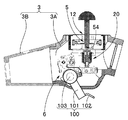
- the operation section 3 of the endoscope 1 includes a front cover section 3A and an operation section main body 3B.
- a bending operation member 5 and a semi-fixed mechanism switching operation member 6 are provided in the front cover portion 3A.
- An angle lever 12 of the bending operation member 5 is provided so as to protrude from one surface side that is the upper surface of the front cover portion 3A in the drawing.
- a switching lever 100 of the semi-fixed mechanism switching operation member 6 is provided on the lower surface of the front cover portion 3A in the figure and on the other surface opposite to the one surface.
- the angle lever 12 is a joystick type as described above, and is tilted.
- the switching lever 100 includes a lever main body 101 and a finger pad 102, and the lever main body 101 is configured to be manually operable counterclockwise about a lever shaft 103.
- the bending operation member 5 includes an angle lever 12 and a swing frame 14, and the swing frame 14 swings as the angle lever 12 is tilted.
- a base end of each of the upper bending wire 11 u and the lower bending wire 11 d is fixed to the swing frame 14 by a wire locking member 15.
- the operating force amount reducing portion connecting portion 54 is provided on the end face side of the angle lever 12 of the present embodiment.
- the first connecting ball portion 23 of the operating force amount reducing unit 20 is movably disposed in the operating force amount reducing unit connecting portion 54.
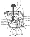
- Reference numeral 20 denotes the above-described operation force amount reduction unit, which is configured by providing a first reduction unit 21, a second reduction unit 22, and a spring 29.
- the first reduction part 21 is provided with a first connecting ball part 23, a first flange 24, and a sliding shaft 25, and the second reduction part 22 is provided with a cylindrical part 26, a second flange 27, and an inclined support.
- a member 81 is provided.
- the spring 29, which is an elastic member disposed between the first flange 24 and the second flange 27, is in a predetermined compressed state, and the support member abutting portion 111 of the frictional resistance member 110 is inclined support member 81.
- the semi-fixed mechanism switching operation member 6 is in a semi-fixed state by being pressed with a predetermined amount of force.
- the inclined support member 81 is a sphere that constitutes an end of the second reduction portion 22.
- the inclined support member 81 is attached to the support member abutting portion 111 of the frictional resistance member 110 so as to be rotatable without falling off.
- symbol 113 is a 1st torsion coil spring
- symbol 114 is an arm member
- symbol 115 is a spring terminal support pin.
- the first torsion coil spring 113 constantly urges the support member abutting portion 111 of the frictional resistance member 110 in a direction in which it is separated from the second reduction portion 22.
- the semi-fixed mechanism switching operation member 6 includes a switching lever 100, a friction resistance member 110, a lever position switching arm 120, a cam 130 formed in a predetermined shape, and a ratchet 140 formed in a predetermined shape shown in FIGS.
- the first plate spring 150 and the second plate spring 160 having a predetermined elasticity and formed in a predetermined shape are provided.
- the switching lever 100 is provided with an operation plate 104 and a resistance member support pin 105 in addition to the lever main body 101, the finger rest portion 102, and the lever shaft 103 described above.
- the operation plate 104 is integrally fixed to the lever shaft 103 and rotates around the lever shaft 103 as the switching lever 100 is operated.
- the resistance member support pin 105 is provided so as to protrude from the back side of the operation plate 104, and the protruding pin portion abuts on and supports the bottom surface 116 of the friction resistance member 110.
- the resistance member support pin 105 also serves as a set screw for fixing the first plate spring 150 to the operation plate 104.
- the lever position switching arm 120 is a friction resistance member arrangement position switching means, and the switching arm main body 121 is arranged to be rotatable about the arm shaft 122.
- the switching arm main body 121 is provided with a spring terminal support pin 123 and a cam pin 125 protruding from the front side.
- Reference numeral 124 denotes a notch, on which the lever shaft 103 can be arranged.
- Reference numeral 126 denotes a second torsion coil spring that constantly urges the cam pin 125 provided on the switching arm main body 121 in a direction in which the cam pin 125 is pressed against the cam surface 131 in the recess of the cam 130.
- the cam 130 and the ratchet 140 are integrally connected to each other and are disposed so as to be rotatable about the dual-purpose shaft 141.
- the first leaf spring 150 rotates the ratchet 140 clockwise as viewed from the front.
- the second leaf spring 160 prevents the ratchet 140 from rotating counterclockwise when viewed from the front.
- the user When the user performs a switching operation from the semi-fixed state to the semi-fixed released state, the user applies any finger to the finger rest 102 and moves the switch lever 100 toward the outer surface of the front cover 3A.
- the cam 130 is also rotated clockwise.
- the cam pin 125 resists the urging force of the second torsion coil spring 126 and the cam surface 131 in the recess of the cam 130.
- the lever position switching arm 120 rotates clockwise about the arm shaft 122 while moving toward the outer cam surface 132 of the convex portion.
- the switching lever 100 is moved to a predetermined operation position near the outer surface of the front cover portion 3A, the friction resistance member 110 and the lever position switching arm 120 are rotated by a predetermined amount, and the lever The shaft 103 is completely removed from the notch 124. At this time, the cam pin 125 is placed on the outer cam surface 132 of the convex portion of the cam 130.
- the second plate spring 160 prevents the arm 120 from rotating in the reverse direction.
- the operator When the operator confirms that the switching lever 100 has been moved to a predetermined operation position in the vicinity of the outer surface of the front cover portion 3A, the operator removes the finger from the finger rest portion 102. Then, since the lever shaft 103 is completely detached from the notch 124, the lever shaft 103 does not contact the lever position switching arm 120 by the urging force of the first torsion coil spring 113, and FIG. As shown, the frictional resistance member 110 is rotated counterclockwise about the resistance member shaft 112. 14A and 14B, the inclined support member 81 and the support member abutting portion 111 are moved by the elastic force of the spring 29. Then, a semi-fixed release state in which the elastic force of the spring 29 is not applied to the support member abutting portion 111 via the inclined support member 81 is achieved.
- the arm member 114 provided on the frictional resistance member 110 abuts on the operation plate 104 so that the operation plate 104 is a lever shaft as shown in FIG. 14A.
- the lever 103 is rotated clockwise around the lever shaft 103.
- the lever main body 101 integrated with the lever shaft 103 is gradually separated from the outer surface of the front cover portion 3A, and the switching lever 100 is different from the semi-fixed state position. The state position is reached.
- the cam 130 As the ratchet 140 rotates, the cam 130 also rotates clockwise. As the cam 130 rotates, the cam pin 125 resists the urging force of the second torsion coil spring 126 and the cam surface of the cam 130 on the convex portion.
- the lever position switching arm 120 rotates clockwise about the arm shaft 122 while moving toward the cam surface 131 in the recess along the direction 132.
- the switching lever 100 is moved to a predetermined operation position near the outer surface of the front cover portion 3A, the friction resistance member 110 and the lever position switching arm 120 are rotated by a predetermined amount, and the lever The shaft 103 is disposed in the notch 124. At this time, the cam pin 125 is placed on the cam surface 131 in the recess of the cam 130.
- the second plate spring 160 prevents the arm 120 from rotating in the reverse direction.
- the operator When the operator confirms that the switching lever 100 has been moved to a predetermined operation position in the vicinity of the outer surface of the front cover portion 3A, the operator removes the finger from the finger rest portion 102. Then, because the lever shaft 103 is disposed in the notch 124, the frictional resistance member 110 rotates about the resistance member shaft 112 counterclockwise by the biasing force of the first torsion coil spring 113. It will be done. 9 and 10, the support member abutting portion 111 presses the inclined support member 81, and the spring 29 disposed between the first flange 24 and the second flange 27 is in a compressed state. Some semi-fixed state.
- the arm member 114 provided on the frictional resistance member 110 abuts on the operation plate 104 so that the operation plate 104 is a lever shaft as shown in FIG. 15A.
- the lever 103 is rotated clockwise around the lever shaft 103.
- the lever main body 101 integrated with the lever shaft 103 is gradually separated from the outer surface of the front cover portion 3A, and the switching lever 100 is semi-fixed different from the semi-fixed release state position. The state position is reached.
- the semi-fixed mechanism switching operation member 6 is configured by providing the spring 150 and the second leaf spring 160 formed in a predetermined shape.
- the switching lever 100 is operated regardless of the switching operation for switching the semi-fixed mechanism switching operation member 6 from the semi-fixed state to the semi-fixed released state or the switching operation for switching from the semi-fixed released state to the semi-fixed state.
- a rotation operation that moves the lever 100 toward the outer surface of the front cover portion 3A, an alternate type changeover switch that can alternately obtain a semi-fixed release state and a semi-fixed state can be realized.
- Rotating operation type alternate type changeover switch greatly improves cleaning workability compared to button type alternate type changeover switch.
- the lever shaft 103 is disposed in the notch 124 in the semi-fixed state, and the lever shaft 103 is disposed at a position away from the notch 124 in the semi-fixed released state, so that the switching lever is disposed in the semi-fixed state. Since the position of the switching lever in the semi-fixed release state is set to a different position, it is possible to easily determine whether or not the switch lever is in the semi-fixed state by visually observing the position of the switching lever.
- the angle lever 12 of the bending operation member 5 is provided on one surface of the front cover portion 3A constituting the operation portion 3 of the endoscope 1, and the semi-fixed mechanism switching operation member 6 is switched on the other surface of the front cover portion 3A.
- the lever 100 for example, an operator who holds the operation unit 3 tilts the angle lever 12 with the thumb of one hand holding and operates the switching lever 100 with fingers other than the thumb. be able to.
- the present invention is not limited to the above-described embodiments, and various modifications can be made without departing from the spirit of the invention.
- ADVANTAGE OF THE INVENTION According to this invention, the bending part can be switched to a semi-fixed state and a semi-fixed release state, and the endoscope excellent in operativity can be implement
Abstract
Description
操作部には、湾曲操作部材としては、軸回りに回動操作される湾曲ノブ或いは湾曲レバー、傾倒操作されるジョイスティック型レバー等が設けられている。
なお、以下の説明に用いる各図面は、模式的に示すものであり、各構成要素を図面上で認識可能な程度に示すために、各部材の寸法関係や縮尺等は、各構成要素毎に異ならせて示している場合がある。したがって、本発明は、これらの図面に記載された構成要素の数量,構成要素の形状,構成要素の大きさの比率及び各構成要素の相対的な位置関係等、図示の形態のみに限定されるものではない。
なお、上述において挿入部2は、先端部2a、湾曲部2b、及び硬性管部2cを連設するいわゆる硬性挿入部としている。しかし、挿入部2は、硬性挿入部に限定されるものでは無く、先端部2a、湾曲部2b、及び柔軟性を有する可撓管部2dを連設した軟性挿入部であってもよい。また、挿入部2内に処置具チャンネルチューブ等が挿通されていてもよい。
湾曲操作部材5は、湾曲部2bを遠隔操作する湾曲操作部として例えばジョイスティックタイプのアングルレバー12を有している。アングルレバー12は、操作部3を構成するゴムブーツ7の弾性保持部7aから突出するように設けられている。アングルレバー12は、傾倒方向の変更及び傾倒角度の変更に伴って湾曲部2bを上下左右の四方向のいずれかに湾曲角度を変更しつつ動作させる。
挿入部2の基端側に設けられた操作部3の外装部材であるハウジング(不図示)の内面にはフレーム8が配設され、フレーム8には湾曲操作ユニット10が設けられている。
湾曲操作ユニット10は、湾曲操作部材5と、操作力量低減部20と、半固定機構切替操作部材6と、を設けて構成されている。
フレーム固定部8gの外周面は、一体面であって、半田等による接合或いは接着剤による接着によってフレーム8の内周面に一体に固設される。
第1の半球凹部8h1は、湾曲機構配設部端面に円形の開口を有する。傾倒用逃がし孔8kは、第1の半球凹部8h1と外部とを結ぶテーパー形状の中心軸方向貫通孔であって、フレーム固定部8gの中央端面に開口を有する。傾倒用逃がし孔8kは、開口に近づくにしたがって径寸法が連続的に大径になる。
この結果、球体13は、アングルレバー12の操作に伴って球体配設部8q内で可動される揺動枠14は、連結軸14aと、十字形状枠部(以下、十字枠と記載する)14bと、操作力量低減部連結部14cと、で構成されている。
連結軸14aは、十字枠14bの一端面中央から予め定めた高さ突出した断面形状が円形の中央棒部である。これに対して、操作力量低減部連結部14cは、十字枠14bの他端面中央から予め定めた高さ突出した例えば円柱形状の中央凸部である。
球部連結部14dは、例えば、連結部用穴14fと、連結部用穴14fに固設されるトメ部材14gとで構成される。連結部用穴14fは、操作力量低減部連結部14cの側周面から揺動枠14の中心軸に直交する軸を中心軸にして形成され、底部は半球形状である。操作力量低減部20の第1連結球部23は、連結部用穴14fを通過して半球形状の底面に導かれる。
つまり、球部連結部14dは、連結部用穴14fの半球形状の底面とトメ部材14gの凹み球面形状の先端面とを組み合わせて構成される。
符号14cは、切欠溝である。切欠溝14cは、操作力量低減部20の第1連結球部23を連結部用穴14fの半球形状の底面に向けて操作部長手軸3aに直交する側方から配置する際、操作力量低減部20の第1連結軸24aが通過する。
操作力量低減部20は、湾曲操作部材5と半固定機構切替操作部材6との間に設けられている。操作力量低減部20は、湾曲操作部形成部(以下、第1低減部と記載する)21と、半固定機構部形成部(以下、第2低減部と記載する)22と、弾性部材である圧縮コイルバネ(以下、バネと略記する)29と、を設けて構成されている。
第1連結球部23は、球状部であって、第1フランジ24から突出された第1連結軸24aの端部に設けられている。第1連結球部23は、上述した湾曲操作部材5の球部連結部14d内に可動自在に配置される。
第2連結球部28は、球状部であって、第2フランジ27から突出された第2連結軸27aの端部に設けられている。第2連結球部28は、上述した半固定機構切替操作部材6の後述する第2球部連結部39内に可動自在に配置される。
操作力量低減部20は、筒部26の外周面にバネ29を配置させた状態で、筒部26の中央穴26h内に摺動軸25を挿入して構成される。この構成において、第1低減部21と第2低減部22とは、第1連結球部23の中心と第2連結球部28の中心とを結ぶ長手軸に沿って、進退移動自在である。
なお、バネ29の一方の座及び他方の座がそれぞれ、第1フランジ24の他面側及び第2フランジ27の一面側にそれぞれ当接していない状態であってもよい。
切替レバー31は、例えば金属製のレバー本体33と、ピニオンギヤ部34とを有している。ピニオンギヤ部34は、操作部内に位置する端部に一体に設けられている。切替レバー31は、軸35を中心に回動自在であり、時計回りへの回転及び反時計回りへの回転が可能である。
なお、切替レバー31の反対側の端部に例えば半球形状の指掛部を設けるようにしてもよい。
キー37は、直方体形状で細長な案内部材であって、フレーム8に一体に設けられている図示されていない地板に固設されている。キー37は、操作部3の操作部長手軸3aに平行に設けられている。
なお、切替レバー31が逆方向である時計回りに回転されると、スライド本体36は、ラックピニオン機構によって矢印Y3B方向とは逆方向に移動される。
すなわち、本実施形態の内視鏡1において、半固定機構切替操作部材6は、切替レバー31及びスライド部材32に操作力量低減部20を含めて構成されている。
図3Aの半固定解除状態において、使用者が図4Aに示すようにアングルレバー12を例えば矢印Y4U方向に傾倒操作すると、揺動枠14が球体13を支点に時計回りに揺動される。この結果、図に示すように上用腕14buに配設されている上湾曲ワイヤ11uが牽引される一方、下湾曲ワイヤ11dが弛緩されて湾曲部2bが図に示すように上方向に湾曲される。
図3Bに示す半固定状態において、本実施形態の内視鏡1は、操作部3内に操作力量低減部20及び操作力量低減部20を含む半固定機構切替操作部材6を設けていることにより、湾曲操作中にアングルレバー12から手指を離したときアングルレバー12の傾倒操作位置を保持することが可能であると共に、アングルレバー12の操作力量が低減されて湾曲部2bを湾曲動作させることを可能である。
したがって、半固定解除状態において、通常の内視鏡と同様に湾曲部2bを湾曲させることが可能で、切替レバー31を操作して半固定状態に切り替えることにより、アングルレバー12から手指を離したとき湾曲部2bの湾曲状態が保持可能になる。
なお、上述した実施形態と同部材には同符号を付して説明を省略する。
切替レバー41は、例えば金属製のレバー本体43と、当接腕部44とを有してL字形状に形作られている。すなわち。当接腕部44の軸は、レバー本体43の軸に対して略直交して設けられている。切替レバー41は、屈曲部分に設けられた第1の軸45を中心に回動自在である。切替レバー41は、レバー本体43の軸が操作部長手軸3aに直交した状態において、該レバー41が第1の軸45を中心に回転しない中立状態になるように配置されている。なお、切替レバー41は、屈曲部分がない形状、たとえば直線形状でもよい。
てこ部材42は、例えば金属製であり、第2球部連結部46を有している。第2球部連結部46には第2連結球部28が可動自在に配置される。符号46hは、第2連結球部用逃がし孔であって、第2球部連結部46と外部とを結ぶテーパー形状の貫通孔であって、開口に近づくにしたがって径寸法が連続的に大径になる。てこ部材42は、第2の軸47を中心に回動自在である。
上述したように揺動枠14にバネ29からの回転トルク(反力付勢力とも記載する)を付与することによってアングルレバー12の操作力量を低減させることが可能である。
一方、アングルレバー12を操作する湾曲操作力量がアシスト力よりも大きな関係であっても、十分に大きなアシスト力を付与しなければ操作力量の低減を十分に図れなくなるおそれがある。
符号54hは、球部用逃がし孔であって、操作力量低減部連結部54と外部とを結ぶテーパー形状の貫通孔であって、開口に近づくにしたがって径寸法が連続的に大径になる。
十字枠63は、上用腕14bu、下用腕14bd、左用腕(不図示)、及び右用腕(不図示)を有している。上用腕14bu、下用腕14bd、左用腕、及び右用腕は、連結軸62の側周面から放射状に突出するように設けられ、本実施形態においては、周方向に90度間隔である。
調整孔64は、連結軸62の軸方向に細長な、十字枠63の他端面及び緩み止めナット配設面にそれぞれ開口を有する、貫通孔である。調整孔64の内周面には雌ネジが形成されている。調整孔64の雌ネジにはレバー調整部53の雄ネジが螺合配置される。
その他の構成は上述した実施形態と同様であり、同部材には同符号を付して説明を省略する。
このとき、作業者は、緩み止めナット59を緩めた状態にする。その後、作業者は、指掛部52を矢印Y7a方向に回転させる。このことによって、レバー調整部53の先端面の十字枠63の他端面からの突出量が回転に伴って増加されて、半径Rが増大していく。
したがって、使用者の好みに合わせて操作力量の調整を容易に行える。
なお、以下の説明において、上述した実施形態と同部材には同符号を付して説明を省略する。
まず、使用者が図9-図12等に示した半固定状態を解除する操作について説明する。
このとき、図13Aに示すように操作板104に固定された第1の板バネ150がラチェット140を時計回りに回転させる。
使用者は、半固定状態に切替操作するとき、上述した半固定解除状態に切り替える操作と同様に、指当て部102に手指の何れか当て付けて切替レバー100を前カバー部3Aの外表面に向けて移動させていく。
このとき、図15Aに示すように操作板104に固定された第1の板バネ150がラチェット140を時計回りに回転させる。
本発明によれば、湾曲部を半固定状態、半固定解除状態に切替可能で、且つ、湾曲部を湾曲させる際の湾曲操作力量を軽減しつつ操作性に優れた内視鏡を実現できる。
Claims (9)
- 被観察部に挿入され、挿入軸方向に対して少なくとも二方向に湾曲可能な湾曲部を設けた挿入部と、
前記挿入部の基端側に連設された操作部と、
先端が前記湾曲部に連結され、牽引により該湾曲部を湾曲させる牽引部材と、
前記牽引部材の基端が連結される、前記操作部に設けられた支点を中心に揺動可能に設けられ、揺動によって前記牽引部材に牽引力を付与する湾曲操作部材と、
第1の端部と第2の端部とを有し、前記第1の端部が前記支点よりも前記挿入部側において前記湾曲操作部材に揺動可能に連結され、該第1の端部を介して前記湾曲操作部材を押圧可能な弾性部材を有する操作力量低減部と、
前記弾性部材が前記湾曲操作部材を押圧する押圧状態と非押圧状態とに切替える切替操作部材と、
を具備することを特徴とする内視鏡。 - 前記切替操作部材は、前記第2の端部に揺動可能に連結されることを特徴とする請求項1に記載の内視鏡。
- 前記切替操作部材は、操作部長手軸方向に進退可能であって、この進退移動によって前記押圧状態と前記非押圧状態とを切り替えることを特徴とする請求項2に記載の内視鏡。
- 前記切替操作部材は、前記操作部に設けた切替レバーとスライド部材とを備え、
前記スライド部材は、前記操作部長手軸方向に進退移動可能に配置され、該スライド部材は、前記切替レバーの操作によって進退移動されることを特徴とする請求項3に記載の内視鏡。 - 前記弾性部材は、コイルバネであることを特徴とする請求項1に記載の内視鏡。
- 前記湾曲操作部材は、前記牽引部材の基端が連結された揺動枠と、該揺動枠を揺動させるアングルレバーとを備え、前記アングルレバーは、当該揺動枠に対してレバー軸方向に進退移動可能に配置されることを特徴とする請求項5に記載の内視鏡。
- 前記揺動枠には、該湾曲操作部材の支点を構成する球状部及び前記アングルレバーが進退移動可能に配置される調整孔が設けられ、
前記アングルレバーには、前記操作力量調整部の第1の端部が揺動可能に連設される操作力量低減部連結部が設けられることを特徴とする請求項6に記載の内視鏡。 - 前記切替操作部材に、湾曲操作中に前記湾曲操作部材から手指を離したとき該湾曲操作部材の揺動位置を保持する摩擦抵抗部材を設けたことを特徴とする請求項4に記載の内視鏡。
- 前記切替操作部材は、
前記第2の端部に揺動可能に連結される連結部を有するてこ部材と、前記てこ部材に当接配置される当接腕部及びレバー本体で構成された切替レバーと、有し、
前記切替レバーを第1の軸に対して回動自在に連結し、前記てこ部材の前記連結部から離間した端部を第2の軸に対して回動自在に連結する構成において、
前記切替レバーは、回動されて中立状態に到達した後、変極点を越えることで前記弾性部材の付勢力によって押圧状態又は非押圧状態に切り替えられることを特徴とする請求項2に記載の内視鏡。
Priority Applications (4)
| Application Number | Priority Date | Filing Date | Title |
|---|---|---|---|
| EP15775949.9A EP3047788A4 (en) | 2014-04-11 | 2015-02-25 | Endoscope |
| JP2015545233A JP5877285B1 (ja) | 2014-04-11 | 2015-02-25 | 内視鏡 |
| CN201580002326.0A CN105682532B (zh) | 2014-04-11 | 2015-02-25 | 内窥镜 |
| US15/132,468 US9500851B2 (en) | 2014-04-11 | 2016-04-19 | Endoscope |
Applications Claiming Priority (2)
| Application Number | Priority Date | Filing Date | Title |
|---|---|---|---|
| JP2014082269 | 2014-04-11 | ||
| JP2014-082269 | 2014-04-11 |
Related Child Applications (1)
| Application Number | Title | Priority Date | Filing Date |
|---|---|---|---|
| US15/132,468 Continuation US9500851B2 (en) | 2014-04-11 | 2016-04-19 | Endoscope |
Publications (1)
| Publication Number | Publication Date |
|---|---|
| WO2015156046A1 true WO2015156046A1 (ja) | 2015-10-15 |
Family
ID=54287627
Family Applications (1)
| Application Number | Title | Priority Date | Filing Date |
|---|---|---|---|
| PCT/JP2015/055421 WO2015156046A1 (ja) | 2014-04-11 | 2015-02-25 | 内視鏡 |
Country Status (5)
| Country | Link |
|---|---|
| US (1) | US9500851B2 (ja) |
| EP (1) | EP3047788A4 (ja) |
| JP (1) | JP5877285B1 (ja) |
| CN (1) | CN105682532B (ja) |
| WO (1) | WO2015156046A1 (ja) |
Cited By (5)
| Publication number | Priority date | Publication date | Assignee | Title |
|---|---|---|---|---|
| EP3047786A4 (en) * | 2013-11-07 | 2017-07-05 | Olympus Corporation | Endoscope |
| JP6234650B1 (ja) * | 2016-07-25 | 2017-11-22 | オリンパス株式会社 | 内視鏡の湾曲操作機構 |
| WO2018020718A1 (ja) * | 2016-07-25 | 2018-02-01 | オリンパス株式会社 | 内視鏡の湾曲操作機構 |
| WO2018128001A1 (ja) * | 2017-01-05 | 2018-07-12 | オリンパス株式会社 | 内視鏡の湾曲操作機構 |
| CN110809427A (zh) * | 2017-07-18 | 2020-02-18 | 富士胶片株式会社 | 内窥镜 |
Families Citing this family (10)
| Publication number | Priority date | Publication date | Assignee | Title |
|---|---|---|---|---|
| WO2018012081A1 (ja) * | 2016-07-12 | 2018-01-18 | オリンパス株式会社 | 内視鏡の湾曲操作機構 |
| US10588495B2 (en) * | 2016-07-28 | 2020-03-17 | Cook Medical Technologies LL | Brake mechanism of a steerable catheter |
| DE112017006560T5 (de) * | 2016-12-26 | 2019-10-02 | Olympus Corporation | Endoskop |
| CN110022749B (zh) * | 2016-12-27 | 2021-12-24 | 奥林巴斯株式会社 | 医疗器械 |
| CN106885841A (zh) * | 2017-02-13 | 2017-06-23 | 深圳市古安泰自动化技术有限公司 | 涡流探伤内窥镜 |
| CN110831482B (zh) * | 2017-06-30 | 2022-01-11 | 奥林巴斯株式会社 | 内窥镜 |
| CN107489944A (zh) * | 2017-07-27 | 2017-12-19 | 安徽工程大学 | 一种具有智能攀爬结构的路灯 |
| EP3763309B1 (en) * | 2018-03-07 | 2023-11-08 | FUJIFILM Corporation | Treatment tool, endoscope device, endoscope system |
| CN109008904B (zh) * | 2018-08-03 | 2020-12-18 | 苏州中科先进技术研究院有限公司 | 一种内窥镜操作部和内窥镜 |
| CN109799604A (zh) * | 2019-03-05 | 2019-05-24 | 华能国际电力股份有限公司玉环电厂 | 一种内窥镜导向辅助装置 |
Citations (6)
| Publication number | Priority date | Publication date | Assignee | Title |
|---|---|---|---|---|
| JP2004129785A (ja) * | 2002-10-09 | 2004-04-30 | Pentax Corp | 内視鏡湾曲操作装置のブレーキ力調整機構 |
| JP2004321492A (ja) * | 2003-04-24 | 2004-11-18 | Olympus Corp | 内視鏡 |
| JP2008035882A (ja) * | 2006-08-01 | 2008-02-21 | Olympus Corp | 内視鏡 |
| JP2010183949A (ja) * | 2009-02-10 | 2010-08-26 | Fujifilm Corp | 内視鏡 |
| JP2012029822A (ja) * | 2010-07-30 | 2012-02-16 | Hoya Corp | 体腔内挿入管類の湾曲操作装置 |
| JP2013223735A (ja) * | 2013-05-21 | 2013-10-31 | Tetsumaru Miyawaki | 内視鏡 |
Family Cites Families (12)
| Publication number | Priority date | Publication date | Assignee | Title |
|---|---|---|---|---|
| JPH0336321Y2 (ja) * | 1986-04-04 | 1991-08-01 | ||
| US5618307A (en) * | 1995-04-03 | 1997-04-08 | Heartport, Inc. | Clamp assembly and method of use |
| US8808166B2 (en) | 2006-06-06 | 2014-08-19 | Olympus Corporation | Endoscope |
| JP2008212239A (ja) * | 2007-02-28 | 2008-09-18 | Olympus Corp | 内視鏡 |
| JP4903917B1 (ja) * | 2010-06-10 | 2012-03-28 | オリンパスメディカルシステムズ株式会社 | 内視鏡保持装置 |
| CN102665524B (zh) * | 2010-12-24 | 2013-09-25 | 奥林巴斯株式会社 | 内窥镜装置 |
| EP2599430B1 (en) * | 2011-04-28 | 2015-03-25 | Olympus Medical Systems Corp. | Endoscope |
| JP5851118B2 (ja) * | 2011-05-25 | 2016-02-03 | オリンパス株式会社 | 内視鏡装置 |
| WO2013108671A1 (ja) * | 2012-01-16 | 2013-07-25 | オリンパスメディカルシステムズ株式会社 | 内視鏡 |
| CN105682529B (zh) * | 2013-11-07 | 2018-05-25 | 奥林巴斯株式会社 | 内窥镜 |
| WO2016024414A1 (ja) * | 2014-08-11 | 2016-02-18 | オリンパス株式会社 | 内視鏡システム |
| JP2015178045A (ja) * | 2015-07-09 | 2015-10-08 | パナソニックIpマネジメント株式会社 | 内視鏡 |
-
2015
- 2015-02-25 CN CN201580002326.0A patent/CN105682532B/zh active Active
- 2015-02-25 WO PCT/JP2015/055421 patent/WO2015156046A1/ja active Application Filing
- 2015-02-25 EP EP15775949.9A patent/EP3047788A4/en not_active Withdrawn
- 2015-02-25 JP JP2015545233A patent/JP5877285B1/ja active Active
-
2016
- 2016-04-19 US US15/132,468 patent/US9500851B2/en active Active
Patent Citations (6)
| Publication number | Priority date | Publication date | Assignee | Title |
|---|---|---|---|---|
| JP2004129785A (ja) * | 2002-10-09 | 2004-04-30 | Pentax Corp | 内視鏡湾曲操作装置のブレーキ力調整機構 |
| JP2004321492A (ja) * | 2003-04-24 | 2004-11-18 | Olympus Corp | 内視鏡 |
| JP2008035882A (ja) * | 2006-08-01 | 2008-02-21 | Olympus Corp | 内視鏡 |
| JP2010183949A (ja) * | 2009-02-10 | 2010-08-26 | Fujifilm Corp | 内視鏡 |
| JP2012029822A (ja) * | 2010-07-30 | 2012-02-16 | Hoya Corp | 体腔内挿入管類の湾曲操作装置 |
| JP2013223735A (ja) * | 2013-05-21 | 2013-10-31 | Tetsumaru Miyawaki | 内視鏡 |
Non-Patent Citations (1)
| Title |
|---|
| See also references of EP3047788A4 * |
Cited By (7)
| Publication number | Priority date | Publication date | Assignee | Title |
|---|---|---|---|---|
| EP3047786A4 (en) * | 2013-11-07 | 2017-07-05 | Olympus Corporation | Endoscope |
| US9743827B2 (en) | 2013-11-07 | 2017-08-29 | Olympus Corporation | Endoscope |
| JP6234650B1 (ja) * | 2016-07-25 | 2017-11-22 | オリンパス株式会社 | 内視鏡の湾曲操作機構 |
| WO2018020718A1 (ja) * | 2016-07-25 | 2018-02-01 | オリンパス株式会社 | 内視鏡の湾曲操作機構 |
| WO2018128001A1 (ja) * | 2017-01-05 | 2018-07-12 | オリンパス株式会社 | 内視鏡の湾曲操作機構 |
| JP6395174B1 (ja) * | 2017-01-05 | 2018-09-26 | オリンパス株式会社 | 内視鏡の湾曲操作機構 |
| CN110809427A (zh) * | 2017-07-18 | 2020-02-18 | 富士胶片株式会社 | 内窥镜 |
Also Published As
| Publication number | Publication date |
|---|---|
| JPWO2015156046A1 (ja) | 2017-04-13 |
| CN105682532A (zh) | 2016-06-15 |
| EP3047788A4 (en) | 2017-07-12 |
| US9500851B2 (en) | 2016-11-22 |
| EP3047788A1 (en) | 2016-07-27 |
| JP5877285B1 (ja) | 2016-03-02 |
| CN105682532B (zh) | 2018-06-29 |
| US20160231556A1 (en) | 2016-08-11 |
Similar Documents
| Publication | Publication Date | Title |
|---|---|---|
| JP5877285B1 (ja) | 内視鏡 | |
| JP6006455B2 (ja) | 内視鏡装置 | |
| JP5881908B1 (ja) | 内視鏡 | |
| US11311178B2 (en) | Endoscope | |
| EP2502548B1 (en) | Endoscope | |
| US10136800B2 (en) | Bending operation device and endoscope | |
| US10524642B2 (en) | Bending operation device and endoscope | |
| WO2016052147A1 (ja) | 湾曲操作機構を備える内視鏡 | |
| US20130102961A1 (en) | Endoscope Combined Deflection Control and Lock | |
| JP6081684B1 (ja) | 内視鏡 | |
| JP6028125B1 (ja) | 内視鏡操作機構および内視鏡 | |
| WO2008018554A1 (en) | Operation device and operation device for endoscope | |
| JPWO2015068468A1 (ja) | 内視鏡 | |
| CN108697303B (zh) | 弯曲操作装置和内窥镜 | |
| JP6223648B1 (ja) | 内視鏡 | |
| JP3215550U (ja) | 気管支鏡の引張コードのための制御機構 | |
| WO2021070389A1 (ja) | 内視鏡の湾曲操作機構 | |
| CN108697305B (zh) | 弯曲操作装置和应用该弯曲操作装置的内窥镜 | |
| JP7178430B2 (ja) | 内視鏡 | |
| KR102660408B1 (ko) | 홀딩 컨트롤러 | |
| US20210353133A1 (en) | Endoscope | |
| JP3722732B2 (ja) | 内視鏡 | |
| JP2013039188A (ja) | アタッチメント及び内視鏡システム | |
| KR200293449Y1 (ko) | 조절식 마우스 | |
| WO2021090446A1 (ja) | 挿入機器 |
Legal Events
| Date | Code | Title | Description |
|---|---|---|---|
| ENP | Entry into the national phase |
Ref document number: 2015545233 Country of ref document: JP Kind code of ref document: A |
|
| 121 | Ep: the epo has been informed by wipo that ep was designated in this application |
Ref document number: 15775949 Country of ref document: EP Kind code of ref document: A1 |
|
| REEP | Request for entry into the european phase |
Ref document number: 2015775949 Country of ref document: EP |
|
| WWE | Wipo information: entry into national phase |
Ref document number: 2015775949 Country of ref document: EP |
|
| NENP | Non-entry into the national phase |
Ref country code: DE |