WO2015156040A1 - 円筒型スパッタリングターゲット用素材の製造方法 - Google Patents
円筒型スパッタリングターゲット用素材の製造方法 Download PDFInfo
- Publication number
- WO2015156040A1 WO2015156040A1 PCT/JP2015/054788 JP2015054788W WO2015156040A1 WO 2015156040 A1 WO2015156040 A1 WO 2015156040A1 JP 2015054788 W JP2015054788 W JP 2015054788W WO 2015156040 A1 WO2015156040 A1 WO 2015156040A1
- Authority
- WO
- WIPO (PCT)
- Prior art keywords
- cylindrical
- sputtering target
- grain size
- less
- crystal grain
- Prior art date
- Legal status (The legal status is an assumption and is not a legal conclusion. Google has not performed a legal analysis and makes no representation as to the accuracy of the status listed.)
- Ceased
Links
Images
Classifications
-
- C—CHEMISTRY; METALLURGY
- C23—COATING METALLIC MATERIAL; COATING MATERIAL WITH METALLIC MATERIAL; CHEMICAL SURFACE TREATMENT; DIFFUSION TREATMENT OF METALLIC MATERIAL; COATING BY VACUUM EVAPORATION, BY SPUTTERING, BY ION IMPLANTATION OR BY CHEMICAL VAPOUR DEPOSITION, IN GENERAL; INHIBITING CORROSION OF METALLIC MATERIAL OR INCRUSTATION IN GENERAL
- C23C—COATING METALLIC MATERIAL; COATING MATERIAL WITH METALLIC MATERIAL; SURFACE TREATMENT OF METALLIC MATERIAL BY DIFFUSION INTO THE SURFACE, BY CHEMICAL CONVERSION OR SUBSTITUTION; COATING BY VACUUM EVAPORATION, BY SPUTTERING, BY ION IMPLANTATION OR BY CHEMICAL VAPOUR DEPOSITION, IN GENERAL
- C23C14/00—Coating by vacuum evaporation, by sputtering or by ion implantation of the coating forming material
- C23C14/22—Coating by vacuum evaporation, by sputtering or by ion implantation of the coating forming material characterised by the process of coating
- C23C14/34—Sputtering
- C23C14/3407—Cathode assembly for sputtering apparatus, e.g. Target
- C23C14/3414—Metallurgical or chemical aspects of target preparation, e.g. casting, powder metallurgy
-
- B—PERFORMING OPERATIONS; TRANSPORTING
- B21—MECHANICAL METAL-WORKING WITHOUT ESSENTIALLY REMOVING MATERIAL; PUNCHING METAL
- B21D—WORKING OR PROCESSING OF SHEET METAL OR METAL TUBES, RODS OR PROFILES WITHOUT ESSENTIALLY REMOVING MATERIAL; PUNCHING METAL
- B21D39/00—Application of procedures in order to connect objects or parts, e.g. coating with sheet metal otherwise than by plating; Tube expanders
- B21D39/08—Tube expanders
-
- B—PERFORMING OPERATIONS; TRANSPORTING
- B22—CASTING; POWDER METALLURGY
- B22D—CASTING OF METALS; CASTING OF OTHER SUBSTANCES BY THE SAME PROCESSES OR DEVICES
- B22D21/00—Casting non-ferrous metals or metallic compounds so far as their metallurgical properties are of importance for the casting procedure; Selection of compositions therefor
- B22D21/02—Casting exceedingly oxidisable non-ferrous metals, e.g. in inert atmosphere
- B22D21/025—Casting heavy metals with high melting point, i.e. 1000 - 1600 degrees C, e.g. Co 1490 degrees C, Ni 1450 degrees C, Mn 1240 degrees C, Cu 1083 degrees C
-
- C—CHEMISTRY; METALLURGY
- C21—METALLURGY OF IRON
- C21D—MODIFYING THE PHYSICAL STRUCTURE OF FERROUS METALS; GENERAL DEVICES FOR HEAT TREATMENT OF FERROUS OR NON-FERROUS METALS OR ALLOYS; MAKING METAL MALLEABLE, e.g. BY DECARBURISATION OR TEMPERING
- C21D8/00—Modifying the physical properties of ferrous metals or ferrous alloys by deformation combined with, or followed by, heat treatment
- C21D8/10—Modifying the physical properties of ferrous metals or ferrous alloys by deformation combined with, or followed by, heat treatment during manufacturing of tubular bodies
-
- C—CHEMISTRY; METALLURGY
- C21—METALLURGY OF IRON
- C21D—MODIFYING THE PHYSICAL STRUCTURE OF FERROUS METALS; GENERAL DEVICES FOR HEAT TREATMENT OF FERROUS OR NON-FERROUS METALS OR ALLOYS; MAKING METAL MALLEABLE, e.g. BY DECARBURISATION OR TEMPERING
- C21D9/00—Heat treatment, e.g. annealing, hardening, quenching or tempering, adapted for particular articles; Furnaces therefor
- C21D9/0068—Heat treatment, e.g. annealing, hardening, quenching or tempering, adapted for particular articles; Furnaces therefor for particular articles not mentioned below
-
- C—CHEMISTRY; METALLURGY
- C22—METALLURGY; FERROUS OR NON-FERROUS ALLOYS; TREATMENT OF ALLOYS OR NON-FERROUS METALS
- C22C—ALLOYS
- C22C9/00—Alloys based on copper
-
- C—CHEMISTRY; METALLURGY
- C22—METALLURGY; FERROUS OR NON-FERROUS ALLOYS; TREATMENT OF ALLOYS OR NON-FERROUS METALS
- C22C—ALLOYS
- C22C9/00—Alloys based on copper
- C22C9/01—Alloys based on copper with aluminium as the next major constituent
-
- C—CHEMISTRY; METALLURGY
- C22—METALLURGY; FERROUS OR NON-FERROUS ALLOYS; TREATMENT OF ALLOYS OR NON-FERROUS METALS
- C22C—ALLOYS
- C22C9/00—Alloys based on copper
- C22C9/05—Alloys based on copper with manganese as the next major constituent
-
- C—CHEMISTRY; METALLURGY
- C22—METALLURGY; FERROUS OR NON-FERROUS ALLOYS; TREATMENT OF ALLOYS OR NON-FERROUS METALS
- C22F—CHANGING THE PHYSICAL STRUCTURE OF NON-FERROUS METALS AND NON-FERROUS ALLOYS
- C22F1/00—Changing the physical structure of non-ferrous metals or alloys by heat treatment or by hot or cold working
-
- C—CHEMISTRY; METALLURGY
- C22—METALLURGY; FERROUS OR NON-FERROUS ALLOYS; TREATMENT OF ALLOYS OR NON-FERROUS METALS
- C22F—CHANGING THE PHYSICAL STRUCTURE OF NON-FERROUS METALS AND NON-FERROUS ALLOYS
- C22F1/00—Changing the physical structure of non-ferrous metals or alloys by heat treatment or by hot or cold working
- C22F1/08—Changing the physical structure of non-ferrous metals or alloys by heat treatment or by hot or cold working of copper or alloys based thereon
-
- C—CHEMISTRY; METALLURGY
- C23—COATING METALLIC MATERIAL; COATING MATERIAL WITH METALLIC MATERIAL; CHEMICAL SURFACE TREATMENT; DIFFUSION TREATMENT OF METALLIC MATERIAL; COATING BY VACUUM EVAPORATION, BY SPUTTERING, BY ION IMPLANTATION OR BY CHEMICAL VAPOUR DEPOSITION, IN GENERAL; INHIBITING CORROSION OF METALLIC MATERIAL OR INCRUSTATION IN GENERAL
- C23C—COATING METALLIC MATERIAL; COATING MATERIAL WITH METALLIC MATERIAL; SURFACE TREATMENT OF METALLIC MATERIAL BY DIFFUSION INTO THE SURFACE, BY CHEMICAL CONVERSION OR SUBSTITUTION; COATING BY VACUUM EVAPORATION, BY SPUTTERING, BY ION IMPLANTATION OR BY CHEMICAL VAPOUR DEPOSITION, IN GENERAL
- C23C14/00—Coating by vacuum evaporation, by sputtering or by ion implantation of the coating forming material
- C23C14/22—Coating by vacuum evaporation, by sputtering or by ion implantation of the coating forming material characterised by the process of coating
- C23C14/34—Sputtering
- C23C14/3407—Cathode assembly for sputtering apparatus, e.g. Target
-
- H—ELECTRICITY
- H01—ELECTRIC ELEMENTS
- H01J—ELECTRIC DISCHARGE TUBES OR DISCHARGE LAMPS
- H01J37/00—Discharge tubes with provision for introducing objects or material to be exposed to the discharge, e.g. for the purpose of examination or processing thereof
- H01J37/32—Gas-filled discharge tubes
- H01J37/34—Gas-filled discharge tubes operating with cathodic sputtering
- H01J37/3411—Constructional aspects of the reactor
- H01J37/3414—Targets
- H01J37/3423—Shape
-
- H—ELECTRICITY
- H01—ELECTRIC ELEMENTS
- H01J—ELECTRIC DISCHARGE TUBES OR DISCHARGE LAMPS
- H01J37/00—Discharge tubes with provision for introducing objects or material to be exposed to the discharge, e.g. for the purpose of examination or processing thereof
- H01J37/32—Gas-filled discharge tubes
- H01J37/34—Gas-filled discharge tubes operating with cathodic sputtering
- H01J37/3411—Constructional aspects of the reactor
- H01J37/3414—Targets
- H01J37/3426—Material
-
- H—ELECTRICITY
- H01—ELECTRIC ELEMENTS
- H01J—ELECTRIC DISCHARGE TUBES OR DISCHARGE LAMPS
- H01J37/00—Discharge tubes with provision for introducing objects or material to be exposed to the discharge, e.g. for the purpose of examination or processing thereof
- H01J37/32—Gas-filled discharge tubes
- H01J37/34—Gas-filled discharge tubes operating with cathodic sputtering
- H01J37/3488—Constructional details of particle beam apparatus not otherwise provided for, e.g. arrangement, mounting, housing, environment; special provisions for cleaning or maintenance of the apparatus
- H01J37/3491—Manufacturing of targets
-
- B—PERFORMING OPERATIONS; TRANSPORTING
- B22—CASTING; POWDER METALLURGY
- B22D—CASTING OF METALS; CASTING OF OTHER SUBSTANCES BY THE SAME PROCESSES OR DEVICES
- B22D11/00—Continuous casting of metals, i.e. casting in indefinite lengths
- B22D11/001—Continuous casting of metals, i.e. casting in indefinite lengths of specific alloys
- B22D11/004—Copper alloys
-
- C—CHEMISTRY; METALLURGY
- C22—METALLURGY; FERROUS OR NON-FERROUS ALLOYS; TREATMENT OF ALLOYS OR NON-FERROUS METALS
- C22C—ALLOYS
- C22C9/00—Alloys based on copper
- C22C9/02—Alloys based on copper with tin as the next major constituent
-
- C—CHEMISTRY; METALLURGY
- C22—METALLURGY; FERROUS OR NON-FERROUS ALLOYS; TREATMENT OF ALLOYS OR NON-FERROUS METALS
- C22C—ALLOYS
- C22C9/00—Alloys based on copper
- C22C9/04—Alloys based on copper with zinc as the next major constituent
-
- C—CHEMISTRY; METALLURGY
- C22—METALLURGY; FERROUS OR NON-FERROUS ALLOYS; TREATMENT OF ALLOYS OR NON-FERROUS METALS
- C22C—ALLOYS
- C22C9/00—Alloys based on copper
- C22C9/06—Alloys based on copper with nickel or cobalt as the next major constituent
Definitions
- the present invention relates to a method for producing a material for a cylindrical sputtering target, which is a material for a cylindrical sputtering target for sputtering a thin film made of copper or a copper alloy.
- Al or an Al alloy is widely used as a flat panel display such as a liquid crystal or an organic EL panel, or a wiring film such as a touch panel.
- miniaturization (narrowing) and thinning of the wiring film have been attempted, and a wiring film having a lower specific resistance than before has been demanded. Accordingly, with the miniaturization and thinning of the wiring film described above, a wiring film using copper or a copper alloy, which is a material having a lower specific resistance than Al or an Al alloy, is provided.
- a sputtering method using a sputtering target is usually applied.
- a sputtering target for example, a flat plate sputtering target as shown in Patent Document 1 and a cylindrical sputtering target as shown in Patent Document 2 have been proposed.
- the outer surface of the cylindrical sputtering target is a sputtering surface and sputtering is performed while rotating the target, it is suitable for continuous film formation as compared with the case of using a flat plate sputtering target. And it has the advantage that it is excellent in the use efficiency of a target.
- the cylindrical sputtering target as described above performs, for example, a hot working process (hot rolling process and hot extrusion process), a drawing drawing process, and an annealing process as disclosed in Patent Document 2. It is manufactured by. In other words, conventionally, a cylindrical ingot is heated to a predetermined temperature that is equal to or higher than the recrystallization temperature and processed into a cylindrical shape, and then further processed and heat-treated to perform a cylindrical sputtering with a predetermined shape. The target was being molded.
- This invention has been made in view of the above-described circumstances, and can efficiently produce a cylindrical sputtering target material made of copper or a copper alloy at a low cost. It aims at providing the manufacturing method of the raw material for cylindrical sputtering targets which can be refined
- a method for producing a cylindrical sputtering target material is a method for producing a cylindrical sputtering target material made of copper or a copper alloy, and is a continuous casting machine or a semi-casting machine.
- a continuous casting process in which a cylindrical ingot is continuously cast using a continuous casting machine, and cold processing and heat treatment are repeatedly performed on the cylindrical ingot, thereby cooling the cylindrical sputtering target material.
- an average crystal grain size of the cylindrical ingot is 20 mm or less
- the cylindrical sputtering target is provided.
- the average crystal grain size on the outer peripheral surface of the material for use is 10 ⁇ m or more and 150 ⁇ m or less, and the crystal grain is twice or more the average crystal grain size
- the area ratio is less than 25% of the total crystal area.
- a cylindrical ingot having an average crystal grain size of 20 mm or less is continuously cast using a continuous casting machine or a semi-continuous casting machine. Since the continuous casting process is provided, the hot working process for forming the ingot into a cylindrical shape can be omitted. Moreover, since continuous casting is performed, a cylindrical ingot having a predetermined length can be obtained. Therefore, the manufacturing cost of the cylindrical sputtering target can be greatly reduced. Also, since it is not hot-worked from an ingot to be formed into a cylindrical shape, it is possible to efficiently produce a cylindrical sputtering target even when targeting a copper alloy with high deformation resistance at high temperatures. Is possible.
- the average crystal grain size of the cylindrical ingot is 20 mm or less
- a cylindrical sputtering target material having an average crystal grain size of 10 ⁇ m or more and 150 ⁇ m or less on the outer peripheral surface, and an area ratio occupied by crystal grains twice as large as the average crystal grain size is less than 25% of the total crystal area It becomes possible to mold.
- the above-mentioned outer peripheral surface becomes a sputter surface, it becomes possible to manufacture a cylindrical sputter target in which the crystal grain size on the sputter surface is uniformly refined.
- the average crystal grain size on the outer peripheral surface of the cylindrical sputtering target material is 10 ⁇ m or more and 150 ⁇ m or less, and the area ratio occupied by crystal grains twice or more the average crystal grain size is less than 25% of the total crystal area
- the outer diameter before and after the processing is expanded within a range of 0% to 30% and after processing.
- the tube expanding step for changing the cross-sectional area within a range of ⁇ 10% to 10% of the cross-sectional area before processing may be performed at least once.
- a tube expanding step is performed in which the outer diameter before and after processing is expanded within a range of 0% to 30% and the sectional area after processing is changed within a range of ⁇ 10% to 10% of the sectional area before processing. Since it has, it becomes possible to shape
- the said heat processing process is 400 degreeC or more and 900 degrees C or less, and the holding time in the said heat processing temperature range is 15 minutes or more and 120 minutes. It is good also as a structure made into the following ranges.
- the heat treatment is performed under conditions where the heat treatment temperature is 400 ° C. or more and 900 ° C. or less and the holding time within the heat treatment temperature range is 15 minutes or more and 120 minutes or less, the processing strain caused by cold working is reduced. It is possible to perform cold working repeatedly. Moreover, it can suppress that a crystal grain coarsens in a heat treatment process. Therefore, it is possible to reliably manufacture a cylindrical sputtering target material having a uniform crystal grain size on the outer peripheral surface.
- a cylindrical sputtering target that can efficiently and inexpensively manufacture a cylindrical sputtering target material made of copper or a copper alloy, and that can uniformly refine the crystal grain size on the outer peripheral surface. It is possible to provide a method for manufacturing a target material.
- the method for manufacturing a cylindrical sputtering target material includes a cylindrical sputtering target material used when a thin film (wiring film) made of copper or a copper alloy is formed on a substrate such as glass by sputtering.
- a cylindrical sputtering target material 10 is manufactured.
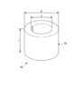
- the cylindrical sputtering target material 10 has a cylindrical shape.
- the outer diameter D is in the range of 140 mm ⁇ D ⁇ 180 mm
- the inner diameter d is in the range of 110 mm ⁇ d ⁇ 135 mm.
- the length L is in the range of 1000 mm ⁇ L ⁇ 4000 mm.
- the outer peripheral surface 11 of the cylindrical sputtering target material 10 is a sputtering surface in the cylindrical sputtering target.
- the cylindrical sputtering target material 10 is made of copper or a copper alloy having a composition corresponding to a thin film made of copper or a copper alloy.
- oxygen-free copper, tough pitch copper, pure copper such as 4N copper, or Mg, Al, Ag, Ti, Zr, Mn, Ca, Cr, Sn, Ni It can be composed of a copper alloy containing one or more selected from Zn, Co, and P.
- the content of one or more selected from Mg, Al, Ag, Ti, Zr, Mn, Ca, Cr, Sn, Ni, Zn, Co, and P is 0.001 mass in total. It is preferable that it is in the range of 10% by mass or more.
- the copper alloy constituting the cylindrical sputtering target material 10 for example, Cu-0.002 to 2 mass% Mg alloy, Cu-0.001 to 10 mass% Al alloy, Cu- Examples thereof include 0.001 to 10% by mass Mn alloy, Cu-0.05 to 4% by mass Ca alloy, Cu-0.01 to 10% by mass Ag alloy, and the like.
- the deformation resistance (deformation stress) at a high temperature tends to be larger than that of pure copper such as oxygen-free copper.
- a copper alloy in which) is 50 N / mm 2 or more is also a copper alloy in which) is 50 N / mm 2 or more. In such a copper alloy having high deformation resistance at high temperatures, it becomes difficult to form a cylindrical shape by, for example, performing hot working on a cylindrical ingot.
- the average crystal grain diameter in an outer peripheral surface is 10 micrometers or more and 150 micrometers or less, and is set to an average crystal grain diameter.
- the area ratio occupied by twice or more of the crystal grains is less than 25% of the total crystal area.
- the crystal grain more than twice this average crystal grain diameter is specified, and the crystal grain Count the diameter and number to calculate the area occupied by the crystal grain more than twice the average crystal grain size, and then count the crystal grain size and number of all the observed crystal grains to calculate the total area Was determined by
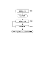
- the cylindrical ingot is continuously formed using a continuous casting machine or a semi-continuous casting machine.
- the cold working step S02 and the heat treatment step S03 are repeatedly performed.
- the cylindrical ingot and the cylindrical ingot are cold worked and heat treated. Cold work is performed on the cylindrical workpiece.
- a cylindrical ingot is continuously produced and cut into a predetermined length using various casting machines such as a vertical continuous casting machine, a horizontal continuous casting machine, and a semi-continuous casting machine.
- the casting conditions are set so that the average crystal grain size of the obtained cylindrical ingot is 20 mm or less.
- the primary cooling and the secondary cooling are controlled according to the dimensions of the ingot, and the drawing speed is set so that the cooling speed of the ingot is 100 ° C./min or more.
- primary cooling was performed using a graphite mold covered with a water cooling jacket and secondary cooling was performed using a water cooling shower.
- the control was performed by the amount of cooling water flowing through a graphite mold covered with a water cooling jacket.
- the average crystal grain size of the cylindrical ingot is preferably finer, but if it is less than 0.01 mm, the manufacturing equipment has a great cost, so the average crystal grain size of the cylindrical ingot is 0. It is desirable to be within the range of 0.01 mm or more and 20 mm or less.
- the lower limit value of the average crystal grain size of the cylindrical ingot is more preferably 1 mm, but is not limited thereto.
- the average crystal grain size of the cylindrical ingot exceeds 20 mm, even if the cold working step S02 and the heat treatment step S03 are repeated, the average crystal grain on the outer peripheral surface of the cylindrical sputtering target material 10 There is a possibility that the area ratio of crystal grains having a diameter of 10 ⁇ m or more and 150 ⁇ m or less and more than twice the average crystal grain size cannot be less than 25% of the total crystal area. For this reason, in this embodiment, the average crystal grain size of the cylindrical ingot is regulated to 20 mm or less. In order to ensure that the above-described effects are achieved, the average crystal grain size of the cylindrical ingot is preferably 20 mm or less, and more preferably 12 mm or less.
- the average crystal grain size of the cylindrical ingot it is preferable to target the crystal structure of the outer peripheral surface serving as a sputtering surface in the cylindrical sputtering target.
- the cross section of the cylindrical ingot may be observed and the average crystal grain size may be 20 mm or less.
- a copper alloy to which various elements are added tends to have an equiaxed crystal structure, and thus the average crystal grain size can be measured by observing the structure as described above.
- the average crystal grain size on the outer peripheral surface of the cylindrical ingot may be 20 mm or less.
- the average crystal grain size on the outer peripheral surface of the cylindrical ingot is preferably 20 mm or less.
- a columnar crystal structure is likely to be formed. Therefore, it is preferable to observe the structure as described above.
- the cold working step S02 cold working is performed on the cylindrical ingot (and the cylindrical work material obtained by subjecting the cylindrical ingot to cold working and heat treatment).
- various methods such as drawing, cold forging, and tube rolling (rolling with a tube reducer) can be applied.
- the cold working step S02 the outer diameter of the cylindrical ingot before the cold working or the cylindrical work material is expanded within the range of 0% to 30% and the sectional area after the cold working is cooled.
- the tube expansion step for changing the cross-sectional area in the range of ⁇ 10% to + 10% of the cross-sectional area before the inter-working may be performed at least once.
- heat treatment is performed on the cold-worked cylindrical workpiece.
- the heat treatment means is not particularly limited, and a batch type heat treatment furnace, a continuous annealing furnace, or the like can be applied.
- the heat treatment step S03 is performed using a batch-type heat treatment furnace. Within the following range.
- a cylindrical ingot is produced by the continuous casting step S01, and the cold working step S02 and the heat treatment step S03 are repeatedly performed on the cylindrical ingot, Cylindrical sputtering target material 10 in which the average crystal grain size on the outer peripheral surface is 10 ⁇ m or more and 150 ⁇ m or less, and the area ratio occupied by crystal grains twice as large as the average crystal grain size is less than 25% of the total crystal area Is formed.
- the average crystal grain size on the outer peripheral surface is preferably 30 ⁇ m or more and 100 ⁇ m or less, but is not limited thereto. 10% of the total crystal area may be the lower limit of the area ratio occupied by crystal grains twice as large as the average crystal grain size. Further, the area ratio occupied by crystal grains twice as large as the average crystal grain size is preferably 10% or more and 20% or less, but is not limited thereto.
- the cylindrical sputtering target material 10 formed as described above is further processed and used as a cylindrical sputtering target.
- the cylindrical sputtering target is used while being rotated around the axis line in the sputtering apparatus, and its outer peripheral surface is used as a sputtering surface.
- the continuous casting step S01 for continuously casting a cylindrical ingot using a continuous casting machine or a semi-continuous casting machine is performed. Since it is provided, the hot working step for forming the ingot into a cylindrical shape can be omitted, and the manufacturing cost can be greatly reduced. Further, since the hot working step can be omitted, a copper alloy having a high deformation resistance at a high temperature, specifically, a deformation resistance (deformation stress) at a hot working temperature (600 ° C. to 900 ° C.) is 50 N / even materials for cylindrical sputtering target consisting mm 2 or more and copper alloy, can be efficiently produced.
- the average crystal grain size of the cylindrical ingot is set to 20 mm or less
- the average crystal grain size on the outer peripheral surface is obtained by repeatedly performing the cold working step S02 and the heat treatment step S03. Is 10 ⁇ m or more and 150 ⁇ m or less, and it is possible to form the cylindrical sputtering target material 10 in which the area ratio occupied by crystal grains twice as large as the average crystal grain size is less than 25% of the total crystal area. Become.
- the cylindrical sputtering target material 10 whose crystal structure is controlled in this way, it is possible to manufacture a cylindrical sputtering target in which the crystal grain size on the sputtering surface is uniformly refined.
- the outer diameter of the cylindrical ingot before machining or the cylindrical workpiece is expanded within the range of 0% to 30% and the sectional area after processing is processed.
- the tube expansion process that changes within the range of ⁇ 10% to + 10% of the previous cross-sectional area is performed at least once, it is larger than the cylindrical ingot produced in the continuous casting process S01. It becomes possible to form the cylindrical sputtering target material 10 having a diameter. Further, by performing the tube expanding step, the processing rate in the cold working step S02 can be secured, and the crystal grains of the cylindrical sputtering target material 10 can be made finer.
- the conditions of the heat treatment step S03 are the heat treatment temperature: 400 ° C. or more and 900 ° C. or less, and the holding time within the heat treatment temperature range: 15 minutes or more and 120 minutes or less.
- the processing strain generated by the processing step S02 can be reduced, and the cold processing step S02 can be repeated. Moreover, it can suppress that a crystal grain coarsens in heat processing process S03.
- a copper alloy containing one or more selected from Mg, Al, Ag, Ti, Zr, Mn, Ca, Cr, Sn, Ni, Zn, Co, and P.
- a cylindrical sputtering target capable of forming a thin film excellent in various characteristics such as resistivity, heat resistance, and corrosion resistance can be manufactured.
- the content of one or more selected from Mg, Al, Ag, Ti, Zr, Mn, Ca, Cr, Sn, Ni, Zn, Co, and P is It is desirable that the total amount be in the range of 0.001% by mass or more and 10% by mass or less.
- the columnar crystal when a cylindrical ingot made of a columnar crystal structure such as oxygen-free copper is produced by the continuous casting step S01, the columnar crystal grows radially inward from the outer peripheral surface. Since the average crystal grain size on the outer peripheral surface of the cylindrical ingot is 20 mm or less, the average crystal grain size on the outer peripheral surface is 10 ⁇ m or more and 150 ⁇ m or less, and more than twice the average crystal grain size It is possible to manufacture the cylindrical sputtering target material 10 in which the area ratio of the crystal grains is less than 25% of the total crystal area.
- the average crystal grain size on the outer peripheral surface of the cylindrical sputtering target material 10 is 10 ⁇ m or more and 150 ⁇ m or less, and the area ratio occupied by crystal grains twice the average crystal grain size is less than 25% of the total crystal area. Therefore, the number of abnormal discharges that occur during sputtering can be reduced.
- the condition of the heat treatment step S03 has been described as the heat treatment temperature: 400 ° C. or more and 900 ° C. or less, and the holding time: 15 minutes or more and 120 minutes or less, but is not limited thereto,
- the heat treatment conditions may be set as appropriate according to the composition and size of the cylindrical sputtering target material to be molded, the heat treatment apparatus, and the like.
- pure copper such as oxygen-free copper, tough pitch copper, and 4N copper, Mg, Al, Ag, Ti, Zr, Mn, Ca, and the like as copper or a copper alloy constituting the cylindrical sputtering target material 10
- a copper alloy containing one or more selected from Cr, Sn, Ni, Zn, Co, and P with the balance being copper and inevitable impurities.
- Other copper or copper alloys may be targeted.
- the content of one or more selected from Mg, Al, Ag, Ti, Zr, Mn, Ca, Cr, Sn, Ni, Zn, Co, and P is 0.001% by mass in total. It is desirable to be in the range of 10% by mass or less.
- a cylindrical ingot (outer diameter 160 mm, inner diameter 100 mm) made of copper or a copper alloy having the composition shown in Table 1 was produced by a vertical continuous casting machine. Cold processing and heat treatment were repeatedly performed on the cylindrical ingot to form a cylindrical sputtering target material. Table 1 shows the diameter expansion value in cold working, the cross-sectional area ratio before and after the working, and the heat treatment conditions. And the cylindrical sputtering target was manufactured using this raw material for cylindrical sputtering targets. And the following evaluation was implemented about the obtained cylindrical ingot, the raw material for cylindrical sputtering targets, and the cylindrical sputtering target.
- ⁇ Average crystal grain size of cylindrical ingot> The average crystal grain size was measured by observing the crystal structure on the outer peripheral surface of the cylindrical ingot. A measurement sample was cut out, the observation surface was polished, and observation with an optical microscope was performed. From the obtained crystal grain boundaries, the number of crystal grains in the 20 mm ⁇ 20 mm area is calculated, and the crystal grain area is calculated by dividing the total length of the crystal grain boundaries in the 20 mm ⁇ 20 mm area by the number of crystal grains. The average crystal grain size was determined by conversion. The measurement results are shown in Table 1.
- An EBSD measurement apparatus (S4300-SE manufactured by HITACHI, OIM Data Collection manufactured by EDAX / TSL) and analysis software (manufactured by EDAX / TSL) using a field emission scanning electron microscope and cutting the measurement sample and polishing the observation surface OIM Data Analysis ver.5.2) was used to identify the grain boundaries. Measurement conditions are: measurement range: 680 ⁇ 1020 ⁇ m / measurement step: 2.0 ⁇ m / take-in time: 20 msec. / Point.
- each measurement point (pixel) within the measurement range on the sample surface is irradiated with an electron beam, and the adjacent measurement is performed by orientation analysis using the backscattered electron beam analysis method.
- the measurement point where the orientation difference between the points was 15 ° or more was defined as a grain boundary.
- From the obtained crystal grain boundary calculate the number of crystal grains in the observation area, calculate the crystal grain area by dividing the total length of the crystal grain boundary in the observation area by the number of crystal grains, and by converting it into a circle, The average grain size was taken. The calculation results are shown in Table 1.
- the average crystal grain size in the cylindrical sputtering target material and the area ratio occupied by crystal grains more than twice the average crystal grain size are outside the scope of the present invention. Therefore, the number of abnormal discharges was large under any conditions of Ar gas and mixed gas. Further, in Comparative Example 2 in which the crystal grain size in the cylindrical ingot exceeds 20 mm, the average crystal grain size in the cylindrical sputtering target material is large, and the area occupied by the crystal grains twice or more the average crystal grain size The ratio was also high, and the crystal grains were coarse and non-uniform. In the sputtering test, the number of abnormal discharges was large under both conditions of Ar gas and mixed gas.
- Example 1-5 of the present invention in which the crystal grain size in the cylindrical ingot was 20 mm or less, the average crystal grain size in the cylindrical sputtering target material was in the range of 10 ⁇ m to 150 ⁇ m, and the average The area ratio occupied by crystal grains more than twice the crystal grain size was also less than 25%, and the crystal grains were relatively fine and uniform. Further, in the sputtering test, it was confirmed that the number of abnormal discharges was reduced under any conditions of Ar gas and mixed gas, and that sputtering could be performed stably.
- a material for a cylindrical sputtering target made of copper or a copper alloy can be produced efficiently and at low cost, and the crystal grain size on the outer peripheral surface is uniform. It is possible to make it fine.
Landscapes
- Chemical & Material Sciences (AREA)
- Engineering & Computer Science (AREA)
- Mechanical Engineering (AREA)
- Materials Engineering (AREA)
- Metallurgy (AREA)
- Organic Chemistry (AREA)
- Physics & Mathematics (AREA)
- Crystallography & Structural Chemistry (AREA)
- Thermal Sciences (AREA)
- Plasma & Fusion (AREA)
- Analytical Chemistry (AREA)
- Chemical Kinetics & Catalysis (AREA)
- Manufacturing & Machinery (AREA)
- Physical Vapour Deposition (AREA)
Abstract
Description
本願は、2014年4月11日に、日本に出願された特願2014-081702号に基づき優先権を主張し、その内容をここに援用する。
そこで、上述の配線膜の微細化および薄膜化にともない、Al又はAl合金よりも比抵抗の低い材料である銅又は銅合金を用いた配線膜が提供されている。
上述のスパッタリングターゲットとしては、例えば特許文献1に示すような平板型スパッタリングターゲットや、特許文献2に示すような円筒型スパッタリングターゲットが提案されている。
また、特許文献2では、無酸素銅を対象としているが、各種元素が添加された銅合金を対象とした場合には、その組成によっては、高温での変形抵抗が高くなるため、熱間加工によって円筒形状に成形することができないおそれがあった。
この場合、熱処理温度が400℃以上900℃以下、前記熱処理温度範囲内での保持時間が15分以上120分以下の範囲内の条件で熱処理を行うので、冷間加工によって生じた加工ひずみを低減することができ、冷間加工を繰り返し行うことが可能となる。また、熱処理工程において、結晶粒が粗大化することを抑制できる。よって、外周面における結晶粒径が均一微細化した円筒型スパッタリングターゲット用素材を確実に製造することが可能となる。
本実施形態に係る円筒型スパッタリングターゲット用素材の製造方法は、ガラス等の基板上に銅又は銅合金からなる薄膜(配線膜)をスパッタによって成膜する際に用いられる円筒型スパッタリングターゲットの素材となる円筒型スパッタリングターゲット用素材10を製造する。
この円筒型スパッタリングターゲット用素材10は、図1に示すように、円筒形状をなしており、例えば外径Dが140mm≦D≦180mmの範囲内、内径dが110mm≦d≦135mmの範囲内、長さLが1000mm≦L≦4000mmの範囲内とされている。
ここで、円筒型スパッタリングターゲット用素材10の外周面11が、円筒型スパッタリングターゲットにおいてスパッタ面とされる。
本実施形態である円筒型スパッタリングターゲット用素材10においては、無酸素銅、タフピッチ銅、4N銅等の純銅、あるいは、Mg、Al、Ag、Ti、Zr、Mn、Ca、Cr、Sn、Ni、Zn、Co、Pの中から選択される1種又は2種以上を含有した銅合金で構成することができる。特に、Mg、Al、Ag、Ti、Zr、Mn、Ca、Cr、Sn、Ni、Zn、Co、Pの中から選択される1種又は2種以上の含有量は、合計で0.001質量%以上10質量%以下の範囲内であることが好ましい。
なお、平均結晶粒径に対して2倍以上の結晶粒が占める面積割合については、平均結晶粒径を算出した後、この平均結晶粒径の2倍以上の結晶粒を特定し、その結晶粒径と個数をカウントして平均結晶粒径に対して2倍以上の結晶粒が占める面積を算出し、さらに観察されたすべての結晶粒の結晶粒径と個数をカウントして全面積を算出することによって求めた。
上述した構成の円筒型スパッタリングターゲット用素材10を製造するために、本実施形態の円筒型スパッタリングターゲット用素材の製造方法においては、連続鋳造機又は半連続鋳造機を用いて円筒状鋳塊を連続鋳造する連続鋳造工程S01と、この円筒状鋳塊に対して冷間加工を行う冷間加工工程S02と、冷間加工工程S02を実施した円筒状加工材に対して熱処理を実施する熱処理工程S03と、を備えている。本実施形態では、これら冷間加工工程S02と熱処理工程S03とを繰り返し実施する構成とされており、冷間加工工程S02では、円筒状鋳塊及びこの円筒状鋳塊を冷間加工及び熱処理した円筒状加工材に対して冷間加工を行う。
ここで、冷間加工工程S02として、冷間加工前の円筒状鋳塊又は円筒状加工材の外径を0%超え30%以下の範囲内で拡げるとともに、冷間加工後の断面積を冷間加工前の断面積の-10%以上+10%以下の範囲内で変化させる拡管工程を少なくとも1回実施してもよい。
また、熱間加工工程を省略可能であることから、高温での変形抵抗が高い銅合金、具体的には熱間加工温度(600℃以上900℃以下)における変形抵抗(変形応力)が50N/mm2以上とされた銅合金からなる円筒型スパッタリングターゲット用素材であっても、効率良く製造することができる。
また、このように結晶組織が制御された円筒型スパッタリングターゲット用素材10を用いることにより、スパッタ面における結晶粒径を均一微細化した円筒型スパッタターゲットを製造可能となる。
例えば、本実施形態では、熱処理工程S03の条件を、熱処理温度:400℃以上900℃以下、保持時間:15分以上120分以下とするものとして説明したが、これに限定されることはなく、成形する円筒型スパッタリングターゲット用素材の組成及びサイズや熱処理を行う装置等に応じて適宜熱処理条件を設定してもよい。
まず、縦型連続鋳造機により、表1に示す組成の銅又は銅合金からなる円筒状鋳塊(外径160mm、内径100mm)を製出した。この円筒状鋳塊に対して冷間加工と熱処理を繰り返し実施し、円筒型スパッタリングターゲット用素材を成形した。なお、冷間加工における拡径値及び加工前後の断面積比、並びに、熱処理条件を表1に示す。そして、この円筒型スパッタリングターゲット用素材を用いて円筒型スパッタリングターゲットを製造した。
そして、得られた円筒状鋳塊、円筒型スパッタリングターゲット用素材、及び、円筒型スパッタリングターゲットについて、以下のような評価を実施した。
円筒状鋳塊の外周面において結晶組織を観察して平均結晶粒径を測定した。測定試料を切り出して観察面を研磨し、光学顕微鏡観察を行った。得られた結晶粒界から、20mm×20mmエリア内の結晶粒子数を算出するとともに、20mm×20mmエリア内の結晶粒界の全長を結晶粒子数で割って結晶粒子面積を算出し、それを円換算することによって平均結晶粒径を求めた。測定結果を表1に示す。
得られた円筒型スパッタリングターゲット用素材の外周面における結晶組織観察を行い、平均結晶粒径を算出した。
測定試料を切り出して観察面を研磨し、電解放出型走査電子顕微鏡を用いたEBSD測定装置(HITACHI社製 S4300-SE,EDAX/TSL社製 OIM Data Collection)と、解析ソフト(EDAX/TSL社製 OIM Data Analysis ver.5.2)によって、結晶粒界を特定した。測定条件は測定範囲:680×1020μm / 測定ステップ:2.0μm / 取込時間:20msec./pointとした。
また、円筒型スパッタリングターゲット用素材の外周面における結晶組織観察を行い、平均結晶粒径に対して2倍以上の結晶粒が占める面積割合を算出した。
上述の手順により平均結晶粒径を算出した後、EBSDにより粒度分布を求め、そこから平均値以上の粒径を算出し、平均結晶粒径の2倍以上の結晶粒径を有する結晶粒を特定した。そして、その特定した結晶粒径と個数をカウントして平均結晶粒径に対して2倍以上の結晶粒が占める面積を算出した。さらに、観察されたすべての結晶粒の結晶粒径と個数をカウントして全面積を算出することによって、平均結晶粒径に対して2倍以上の結晶粒が占める面積割合を求めた。算出結果を表1に示す。
得られた円筒型スパッタリングターゲットを用いて、以下の条件でスパッタ試験を実施し、スパッタ装置に付属されたアーキングカウンターを用いて、異常放電回数をカウントした。なお、雰囲気ガスとして、配線膜を形成する際に使用される「Arガス」、及び、酸素含有膜を形成する際に使用される「混合ガス」の2条件でスパッタ試験を実施した。
評価結果を表1に示す。
電源:直流方式
スパッタ出力:600W
スパッタ圧:0.2Pa
スパッタ時間:8時間
到達真空度:4×10⁻⁵Pa
雰囲気ガス組成:Arガス/混合ガス(90vol%Ar+10vol%O)

また、円筒状鋳塊における結晶粒径が20mmを超える比較例2においては、円筒型スパッタリングターゲット用素材における平均結晶粒径が大きく、平均結晶粒径に対して2倍以上の結晶粒が占める面積割合も高く、結晶粒が粗大で不均一となった。スパッタ試験においては、Arガス及び混合ガスのいずれの条件でも異常放電回数が多かった。
11 外周面
S01 連続鋳造工程
S02 冷間加工工程
S03 熱処理工程
Claims (3)
- 銅又は銅合金からなる円筒型スパッタリングターゲット用素材の製造方法であって、
連続鋳造機又は半連続鋳造機を用いて、平均結晶粒径が20mm以下の円筒状鋳塊を鋳造する連続鋳造工程と、
この円筒状鋳塊及び前記円筒状鋳塊を加工した円筒状加工材に対して冷間加工と熱処理を繰り返し実施することにより、外周面における平均結晶粒径が10μm以上150μm以下、かつ、平均結晶粒径に対して2倍以上の結晶粒が占める面積割合が全結晶面積の25%未満とされた前記円筒型スパッタリングターゲット用素材を成形する冷間加工工程及び熱処理工程と、を備えている円筒型スパッタリングターゲット用素材の製造方法。 - 前記冷間加工工程として、前記円筒状鋳塊又は前記円筒状加工材の外径を0%超え30%以下の範囲内で拡げるとともに、加工後の断面積を加工前の断面積の-10%以上10%以下の範囲内で変化させる拡管工程を少なくとも1回以上実施する請求項1に記載の円筒型スパッタリングターゲット用素材の製造方法。
- 前記熱処理工程は、熱処理温度が400℃以上900℃以下、前記熱処理温度範囲内での保持時間が15分以上120分以下の範囲内とされている請求項1又は2に記載の円筒型スパッタリングターゲット用素材の製造方法。
Priority Applications (5)
| Application Number | Priority Date | Filing Date | Title |
|---|---|---|---|
| DE112015000124.7T DE112015000124B4 (de) | 2014-04-11 | 2015-02-20 | Herstellungsverfahren für zylindrisches Sputter-Target-Material |
| US14/911,236 US9982335B2 (en) | 2014-04-11 | 2015-02-20 | Manufacturing method of cylindrical sputtering target material |
| KR1020167021162A KR20160133415A (ko) | 2014-04-11 | 2015-02-20 | 원통형 스퍼터링 타깃용 소재의 제조 방법 |
| KR1020167000741A KR20160009113A (ko) | 2014-04-11 | 2015-02-20 | 원통형 스퍼터링 타깃용 소재의 제조 방법 |
| CN201580001520.7A CN105473755B (zh) | 2014-04-11 | 2015-02-20 | 圆筒型溅射靶用原材料的制造方法 |
Applications Claiming Priority (2)
| Application Number | Priority Date | Filing Date | Title |
|---|---|---|---|
| JP2014-081702 | 2014-04-11 | ||
| JP2014081702A JP5828350B2 (ja) | 2014-04-11 | 2014-04-11 | 円筒型スパッタリングターゲット用素材の製造方法 |
Publications (1)
| Publication Number | Publication Date |
|---|---|
| WO2015156040A1 true WO2015156040A1 (ja) | 2015-10-15 |
Family
ID=54287621
Family Applications (1)
| Application Number | Title | Priority Date | Filing Date |
|---|---|---|---|
| PCT/JP2015/054788 Ceased WO2015156040A1 (ja) | 2014-04-11 | 2015-02-20 | 円筒型スパッタリングターゲット用素材の製造方法 |
Country Status (7)
| Country | Link |
|---|---|
| US (1) | US9982335B2 (ja) |
| JP (1) | JP5828350B2 (ja) |
| KR (2) | KR20160009113A (ja) |
| CN (1) | CN105473755B (ja) |
| DE (1) | DE112015000124B4 (ja) |
| TW (1) | TWI534277B (ja) |
| WO (1) | WO2015156040A1 (ja) |
Families Citing this family (12)
| Publication number | Priority date | Publication date | Assignee | Title |
|---|---|---|---|---|
| JP6900642B2 (ja) * | 2016-08-26 | 2021-07-07 | 三菱マテリアル株式会社 | スパッタリングターゲット用銅素材 |
| JP6308278B2 (ja) * | 2016-10-07 | 2018-04-11 | 三菱マテリアル株式会社 | 円筒型スパッタリングターゲット用熱間押出素材、及び、円筒型スパッタリングターゲットの製造方法 |
| US10760156B2 (en) * | 2017-10-13 | 2020-09-01 | Honeywell International Inc. | Copper manganese sputtering target |
| CN109628897A (zh) * | 2018-12-06 | 2019-04-16 | 新疆众和股份有限公司 | 一种高纯铝硅合金溅射靶材坯料及其制备方法 |
| US11450516B2 (en) | 2019-08-14 | 2022-09-20 | Honeywell International Inc. | Large-grain tin sputtering target |
| CN111286702A (zh) * | 2020-02-25 | 2020-06-16 | 广州市尤特新材料有限公司 | 一种旋转银铜靶材及制备方法 |
| CN112609104B (zh) * | 2020-10-20 | 2021-09-17 | 陕西斯瑞新材料股份有限公司 | 一种耐热铜合金的半连续金属铸造工艺及其应用 |
| CN112981335B (zh) * | 2021-02-09 | 2022-10-04 | 丰联科光电(洛阳)股份有限公司 | 一种高纯铜管靶的制备方法 |
| JP7188480B2 (ja) * | 2021-03-02 | 2022-12-13 | 三菱マテリアル株式会社 | 熱延銅合金板およびスパッタリングターゲット |
| CN112975102B (zh) * | 2021-03-04 | 2023-06-23 | 宁波江丰电子材料股份有限公司 | 一种钴靶材与铜背板的扩散焊接方法 |
| CN113846298B (zh) * | 2021-09-27 | 2023-11-07 | 宁波江丰热等静压技术有限公司 | 一种铽靶坯的制备方法 |
| CN115287497B (zh) * | 2022-07-29 | 2023-05-26 | 先导薄膜材料(广东)有限公司 | 一种锡银铜靶材及其制备方法 |
Citations (2)
| Publication number | Priority date | Publication date | Assignee | Title |
|---|---|---|---|---|
| WO2013031381A1 (ja) * | 2011-08-29 | 2013-03-07 | Jx日鉱日石金属株式会社 | Cu-Ga合金スパッタリングターゲット及びその製造方法 |
| JP2013076129A (ja) * | 2011-09-30 | 2013-04-25 | Hitachi Cable Ltd | スパッタリングターゲット及びその製造方法 |
Family Cites Families (21)
| Publication number | Priority date | Publication date | Assignee | Title |
|---|---|---|---|---|
| US2365208A (en) * | 1942-07-15 | 1944-12-19 | Bridgeport Brass Co | Manufacture of copper base alloy products |
| JPS5027476B2 (ja) | 1972-11-17 | 1975-09-08 | ||
| US4110132A (en) | 1976-09-29 | 1978-08-29 | Olin Corporation | Improved copper base alloys |
| JP2862727B2 (ja) | 1992-05-12 | 1999-03-03 | 同和鉱業株式会社 | 金属薄膜形成用スパッタリング・ターゲット並びにその製造方法 |
| US5590389A (en) * | 1994-12-23 | 1996-12-31 | Johnson Matthey Electronics, Inc. | Sputtering target with ultra-fine, oriented grains and method of making same |
| US20030052000A1 (en) | 1997-07-11 | 2003-03-20 | Vladimir Segal | Fine grain size material, sputtering target, methods of forming, and micro-arc reduction method |
| US6878250B1 (en) | 1999-12-16 | 2005-04-12 | Honeywell International Inc. | Sputtering targets formed from cast materials |
| EP1407058A2 (en) | 2001-07-19 | 2004-04-14 | Honeywell International, Inc. | Sputtering targets, sputter reactors, methods of forming cast ingots, and methods of forming metallic articles |
| EE05493B1 (et) * | 2006-03-07 | 2011-12-15 | Cabot Corporation | Meetod l?pliku paksusega metallesemete valmistamiseks, saadud metallplaat ja selle valmistamiseks kasutatav BCC- metall |
| JP2009262234A (ja) * | 2008-03-31 | 2009-11-12 | Sumitomo Chemical Co Ltd | Cu−Ga合金の圧延方法 |
| JP5092939B2 (ja) * | 2008-07-01 | 2012-12-05 | 日立電線株式会社 | Tft用平板型銅スパッタリングターゲット材及びスパッタリング方法 |
| US20100101948A1 (en) * | 2008-10-24 | 2010-04-29 | Applied Materials, Inc. | Rotatable sputter target base, rotatable sputter target, coating installation, method of producing a rotatable sputter target, target base connection means, and method of connecting a rotatable target base device for sputtering installations to a target base support |
| JP4974198B2 (ja) | 2009-09-18 | 2012-07-11 | 古河電気工業株式会社 | スパッタリングターゲットに用いられる銅材料およびその製造方法 |
| JP5491845B2 (ja) * | 2009-12-16 | 2014-05-14 | 株式会社Shカッパープロダクツ | スパッタリングターゲット材 |
| KR20110110004A (ko) * | 2010-03-31 | 2011-10-06 | 스미또모 가가꾸 가부시끼가이샤 | 구리 갈륨 합금 및 그 제조 방법 |
| JP5607512B2 (ja) | 2010-11-24 | 2014-10-15 | 古河電気工業株式会社 | 円筒状ターゲット材、その製造方法、及び、そのシート被覆方法 |
| JP5723247B2 (ja) * | 2011-09-09 | 2015-05-27 | 株式会社Shカッパープロダクツ | 円筒型スパッタリングターゲット材、それを用いた配線基板及び薄膜トランジスタの製造方法 |
| CN104583452B (zh) * | 2012-08-22 | 2017-07-21 | Jx日矿日石金属株式会社 | 铟制圆筒型溅射靶及其制造方法 |
| JP2014081702A (ja) | 2012-10-15 | 2014-05-08 | Renesas Electronics Corp | レイアウト密度検証方法及びプログラム |
| CN103225066B (zh) * | 2012-12-28 | 2015-04-29 | 中国神华能源股份有限公司 | 一种溅射用铜镓合金靶材及其制备方法 |
| JP5622012B2 (ja) * | 2013-03-29 | 2014-11-12 | 三菱マテリアル株式会社 | 円筒型スパッタリングターゲット及びその製造方法 |
-
2014
- 2014-04-11 JP JP2014081702A patent/JP5828350B2/ja active Active
-
2015
- 2015-02-20 US US14/911,236 patent/US9982335B2/en active Active
- 2015-02-20 KR KR1020167000741A patent/KR20160009113A/ko not_active Ceased
- 2015-02-20 CN CN201580001520.7A patent/CN105473755B/zh active Active
- 2015-02-20 DE DE112015000124.7T patent/DE112015000124B4/de active Active
- 2015-02-20 WO PCT/JP2015/054788 patent/WO2015156040A1/ja not_active Ceased
- 2015-02-20 KR KR1020167021162A patent/KR20160133415A/ko not_active Ceased
- 2015-02-24 TW TW104105829A patent/TWI534277B/zh active
Patent Citations (2)
| Publication number | Priority date | Publication date | Assignee | Title |
|---|---|---|---|---|
| WO2013031381A1 (ja) * | 2011-08-29 | 2013-03-07 | Jx日鉱日石金属株式会社 | Cu-Ga合金スパッタリングターゲット及びその製造方法 |
| JP2013076129A (ja) * | 2011-09-30 | 2013-04-25 | Hitachi Cable Ltd | スパッタリングターゲット及びその製造方法 |
Also Published As
| Publication number | Publication date |
|---|---|
| JP5828350B2 (ja) | 2015-12-02 |
| DE112015000124B4 (de) | 2018-04-26 |
| CN105473755B (zh) | 2017-05-17 |
| US9982335B2 (en) | 2018-05-29 |
| TW201538758A (zh) | 2015-10-16 |
| KR20160009113A (ko) | 2016-01-25 |
| KR20160133415A (ko) | 2016-11-22 |
| JP2015203125A (ja) | 2015-11-16 |
| TWI534277B (zh) | 2016-05-21 |
| CN105473755A (zh) | 2016-04-06 |
| DE112015000124T5 (de) | 2016-07-14 |
| US20160194749A1 (en) | 2016-07-07 |
Similar Documents
| Publication | Publication Date | Title |
|---|---|---|
| JP5828350B2 (ja) | 円筒型スパッタリングターゲット用素材の製造方法 | |
| JP5783293B1 (ja) | 円筒型スパッタリングターゲット用素材 | |
| JP5752736B2 (ja) | スパッタリング用ターゲット | |
| JP5464352B2 (ja) | 均一かつ微細結晶組織を有する高純度銅加工材の製造方法 | |
| KR101690394B1 (ko) | 탄탈 스퍼터링 타깃의 제조 방법 | |
| TWI485272B (zh) | Pure copper plate manufacturing methods and pure copper plate | |
| JP7704809B2 (ja) | 銅マンガンスパッタリングターゲット | |
| JP2014051709A (ja) | 熱延銅板 | |
| JP2017150015A (ja) | スパッタリングターゲット、およびスパッタリングターゲットの製造方法 | |
| WO2019058721A1 (ja) | スパッタリング用チタンターゲット及びその製造方法、並びにチタン含有薄膜の製造方法 | |
| JPWO2016190160A1 (ja) | タンタルスパッタリングターゲット及びその製造方法 | |
| JP4756974B2 (ja) | Ni3(Si,Ti)系箔及びその製造方法 | |
| TW201704493A (zh) | 鉭濺鍍靶及其製造方法 | |
| JP5382518B2 (ja) | チタン材 | |
| JP6202131B1 (ja) | 銅合金製バッキングチューブ及び銅合金製バッキングチューブの製造方法 | |
| KR101374281B1 (ko) | 스퍼터링 타겟용 탄탈륨 판재 및 그 제조방법 | |
| JP6595188B2 (ja) | スパッタリングターゲットの製造方法 | |
| JP2021021127A (ja) | 銅合金材料及び熱交換器 | |
| CN121428340A (zh) | 一种高强高塑性亚稳β钛合金及其制备方法 |
Legal Events
| Date | Code | Title | Description |
|---|---|---|---|
| WWE | Wipo information: entry into national phase |
Ref document number: 201580001520.7 Country of ref document: CN |
|
| 121 | Ep: the epo has been informed by wipo that ep was designated in this application |
Ref document number: 15776328 Country of ref document: EP Kind code of ref document: A1 |
|
| ENP | Entry into the national phase |
Ref document number: 20167000741 Country of ref document: KR Kind code of ref document: A |
|
| WWE | Wipo information: entry into national phase |
Ref document number: 14911236 Country of ref document: US |
|
| WWE | Wipo information: entry into national phase |
Ref document number: 112015000124 Country of ref document: DE |
|
| 122 | Ep: pct application non-entry in european phase |
Ref document number: 15776328 Country of ref document: EP Kind code of ref document: A1 |