WO2015152185A1 - インクジェットヘッドの駆動方法及びインクジェット記録装置 - Google Patents
インクジェットヘッドの駆動方法及びインクジェット記録装置 Download PDFInfo
- Publication number
- WO2015152185A1 WO2015152185A1 PCT/JP2015/060017 JP2015060017W WO2015152185A1 WO 2015152185 A1 WO2015152185 A1 WO 2015152185A1 JP 2015060017 W JP2015060017 W JP 2015060017W WO 2015152185 A1 WO2015152185 A1 WO 2015152185A1
- Authority
- WO
- WIPO (PCT)
- Prior art keywords
- pulse
- drive signal
- contraction
- droplet
- expansion
- Prior art date
- Legal status (The legal status is an assumption and is not a legal conclusion. Google has not performed a legal analysis and makes no representation as to the accuracy of the status listed.)
- Ceased
Links
Images






Classifications
-
- B—PERFORMING OPERATIONS; TRANSPORTING
- B41—PRINTING; LINING MACHINES; TYPEWRITERS; STAMPS
- B41J—TYPEWRITERS; SELECTIVE PRINTING MECHANISMS, i.e. MECHANISMS PRINTING OTHERWISE THAN FROM A FORME; CORRECTION OF TYPOGRAPHICAL ERRORS
- B41J2/00—Typewriters or selective printing mechanisms characterised by the printing or marking process for which they are designed
- B41J2/005—Typewriters or selective printing mechanisms characterised by the printing or marking process for which they are designed characterised by bringing liquid or particles selectively into contact with a printing material
- B41J2/01—Ink jet
- B41J2/015—Ink jet characterised by the jet generation process
- B41J2/04—Ink jet characterised by the jet generation process generating single droplets or particles on demand
- B41J2/045—Ink jet characterised by the jet generation process generating single droplets or particles on demand by pressure, e.g. electromechanical transducers
- B41J2/04501—Control methods or devices therefor, e.g. driver circuits, control circuits
- B41J2/04581—Control methods or devices therefor, e.g. driver circuits, control circuits controlling heads based on piezoelectric elements
-
- B—PERFORMING OPERATIONS; TRANSPORTING
- B41—PRINTING; LINING MACHINES; TYPEWRITERS; STAMPS
- B41J—TYPEWRITERS; SELECTIVE PRINTING MECHANISMS, i.e. MECHANISMS PRINTING OTHERWISE THAN FROM A FORME; CORRECTION OF TYPOGRAPHICAL ERRORS
- B41J2/00—Typewriters or selective printing mechanisms characterised by the printing or marking process for which they are designed
- B41J2/005—Typewriters or selective printing mechanisms characterised by the printing or marking process for which they are designed characterised by bringing liquid or particles selectively into contact with a printing material
- B41J2/01—Ink jet
- B41J2/015—Ink jet characterised by the jet generation process
- B41J2/04—Ink jet characterised by the jet generation process generating single droplets or particles on demand
- B41J2/045—Ink jet characterised by the jet generation process generating single droplets or particles on demand by pressure, e.g. electromechanical transducers
- B41J2/04501—Control methods or devices therefor, e.g. driver circuits, control circuits
- B41J2/04573—Timing; Delays
-
- B—PERFORMING OPERATIONS; TRANSPORTING
- B41—PRINTING; LINING MACHINES; TYPEWRITERS; STAMPS
- B41J—TYPEWRITERS; SELECTIVE PRINTING MECHANISMS, i.e. MECHANISMS PRINTING OTHERWISE THAN FROM A FORME; CORRECTION OF TYPOGRAPHICAL ERRORS
- B41J2/00—Typewriters or selective printing mechanisms characterised by the printing or marking process for which they are designed
- B41J2/005—Typewriters or selective printing mechanisms characterised by the printing or marking process for which they are designed characterised by bringing liquid or particles selectively into contact with a printing material
- B41J2/01—Ink jet
- B41J2/015—Ink jet characterised by the jet generation process
- B41J2/04—Ink jet characterised by the jet generation process generating single droplets or particles on demand
- B41J2/045—Ink jet characterised by the jet generation process generating single droplets or particles on demand by pressure, e.g. electromechanical transducers
- B41J2/04501—Control methods or devices therefor, e.g. driver circuits, control circuits
- B41J2/04588—Control methods or devices therefor, e.g. driver circuits, control circuits using a specific waveform
-
- B—PERFORMING OPERATIONS; TRANSPORTING
- B41—PRINTING; LINING MACHINES; TYPEWRITERS; STAMPS
- B41J—TYPEWRITERS; SELECTIVE PRINTING MECHANISMS, i.e. MECHANISMS PRINTING OTHERWISE THAN FROM A FORME; CORRECTION OF TYPOGRAPHICAL ERRORS
- B41J2/00—Typewriters or selective printing mechanisms characterised by the printing or marking process for which they are designed
- B41J2/005—Typewriters or selective printing mechanisms characterised by the printing or marking process for which they are designed characterised by bringing liquid or particles selectively into contact with a printing material
- B41J2/01—Ink jet
- B41J2/015—Ink jet characterised by the jet generation process
- B41J2/04—Ink jet characterised by the jet generation process generating single droplets or particles on demand
- B41J2/045—Ink jet characterised by the jet generation process generating single droplets or particles on demand by pressure, e.g. electromechanical transducers
- B41J2/04501—Control methods or devices therefor, e.g. driver circuits, control circuits
- B41J2/04593—Dot-size modulation by changing the size of the drop
-
- B—PERFORMING OPERATIONS; TRANSPORTING
- B41—PRINTING; LINING MACHINES; TYPEWRITERS; STAMPS
- B41J—TYPEWRITERS; SELECTIVE PRINTING MECHANISMS, i.e. MECHANISMS PRINTING OTHERWISE THAN FROM A FORME; CORRECTION OF TYPOGRAPHICAL ERRORS
- B41J2/00—Typewriters or selective printing mechanisms characterised by the printing or marking process for which they are designed
- B41J2/005—Typewriters or selective printing mechanisms characterised by the printing or marking process for which they are designed characterised by bringing liquid or particles selectively into contact with a printing material
- B41J2/01—Ink jet
- B41J2/015—Ink jet characterised by the jet generation process
- B41J2/04—Ink jet characterised by the jet generation process generating single droplets or particles on demand
- B41J2/045—Ink jet characterised by the jet generation process generating single droplets or particles on demand by pressure, e.g. electromechanical transducers
- B41J2/04501—Control methods or devices therefor, e.g. driver circuits, control circuits
- B41J2/04595—Dot-size modulation by changing the number of drops per dot
-
- B—PERFORMING OPERATIONS; TRANSPORTING
- B41—PRINTING; LINING MACHINES; TYPEWRITERS; STAMPS
- B41J—TYPEWRITERS; SELECTIVE PRINTING MECHANISMS, i.e. MECHANISMS PRINTING OTHERWISE THAN FROM A FORME; CORRECTION OF TYPOGRAPHICAL ERRORS
- B41J2202/00—Embodiments of or processes related to ink-jet or thermal heads
- B41J2202/01—Embodiments of or processes related to ink-jet heads
- B41J2202/06—Heads merging droplets coming from the same nozzle
-
- B—PERFORMING OPERATIONS; TRANSPORTING
- B41—PRINTING; LINING MACHINES; TYPEWRITERS; STAMPS
- B41J—TYPEWRITERS; SELECTIVE PRINTING MECHANISMS, i.e. MECHANISMS PRINTING OTHERWISE THAN FROM A FORME; CORRECTION OF TYPOGRAPHICAL ERRORS
- B41J2202/00—Embodiments of or processes related to ink-jet or thermal heads
- B41J2202/01—Embodiments of or processes related to ink-jet heads
- B41J2202/10—Finger type piezoelectric elements
Definitions
- the present invention relates to an ink-jet head driving method and an ink-jet recording apparatus, and more particularly to an ink-jet head driving method and an ink-jet recording apparatus that can be stably formed in a short driving cycle when discharging large droplets.
- gradation expression is performed by changing the dot diameter of one pixel when the droplets ejected from the nozzles of an inkjet head are landed on a medium to form pixels composed of dots.
- a method of changing the dot diameter for gradation expression there are a method of changing the number of droplets ejected from the same nozzle within one pixel period, a method of changing a drive signal according to the dot size, and the like.
- the former method of changing the dot diameter has the advantage that gradation can be expressed easily by simply changing the number of drive signals applied within one pixel period.
- the number of drive signals is increased in order to form a large dot, the pixel period becomes longer, and there is a problem in performing high frequency driving. For this reason, there is a need for a device that can stably form large droplets in a shorter driving cycle.
- Patent Documents 1 to 3 Conventionally, there are methods described in Patent Documents 1 to 3 as driving methods of an ink jet head.
- Patent Document 1 when ejecting at least two droplets that are continuously ejected from the same nozzle at different speeds, the slower one is ejected before the faster one. It is described that one pixel is formed by overlapping and adhering in one pixel.
- Patent Document 2 discloses a drive signal composed of a rectangular wave, a first pulse for expanding the volume of the pressure chamber, a second pulse for contracting the volume of the pressure chamber, and a third pulse for expanding the volume of the pressure chamber. It is described that a drive signal for sequentially generating a fourth pulse for contracting the volume of the pressure chamber is applied.
- the third pulse has a shorter pulse width than the first pulse, and the fourth pulse has a shorter pulse width than the second pulse.
- the time difference between the pulse width center of the first pulse and the pulse width center of the third pulse is 1AL
- the time difference between the pulse width center of the second pulse and the pulse width center of the fourth pulse is 1AL
- the pulse width of the first pulse And the ratio of the pulse width of the third pulse and the ratio of the pulse width of the second pulse to the pulse width of the fourth pulse according to the attenuation rate of the residual vibration of the ink in the pressure chamber,
- the pressure wave generated by the second pulse is canceled by the third pulse and the fourth pulse.
- the ink ejection volume is changed by changing the ratio of the pulse widths of the first pulse and the second pulse based on the gradation information, and gradation printing is performed.
- this method in order to adjust the time difference and the ratio of the third pulse and the fourth pulse from the center of the pulse width to a predetermined value according to the change in the pulse width of the first pulse and the second pulse, There is a problem that requires complicated control.
- Patent Document 3 describes that the pulse width of the first ejection pulse signal to be applied first is 0.35T to 0.65T, and T Subsequent droplets ejected from the nozzle by the first ejection pulse signal are assumed to be T from the pulse width of the ejection pulse signal applied thereafter and T as the time interval between the first ejection pulse signal and the subsequent ejection pulse signal. It is described that a droplet by a second ejection pulse signal is ejected from a nozzle before leaving.
- the actuator wall With each ejection pulse signal, the actuator wall is deformed to increase the volume of the ink flow path, and after a certain period of time, the actuator wall returns to the state before deformation, and ink droplets are ejected by applying pressure to the ink.
- the droplet ejected by the second ejection pulse signal catches up with the droplet ejected by the first ejection pulse signal, and a large droplet is ejected.
- the present inventor paid attention to a technique for ejecting a plurality of droplets from the same nozzle and combining them during flight immediately after ejection to form a large droplet. .
- this method compared with the case where one large droplet having the same droplet amount is ejected from the nozzle, the large droplet can be ejected while suppressing the droplet velocity. Adjustment does not have to be complicated.
- the satellite is a small droplet (splash) that is formed as a secondary component behind the droplet (main droplet) ejected from the nozzle, which may cause a reduction in image quality.
- Patent Document 3 discloses a technique for forming a large droplet by combining a plurality of droplets during flight, but the present inventors have confirmed that this is sufficient from the viewpoint of suppressing the generation of satellites. It was not a thing.
- the present invention provides an ink jet head driving method and an ink jet recording apparatus that are capable of forming large stable liquid droplets efficiently in a short driving cycle and performing high-quality image recording while suppressing the generation of satellites. It is an issue to provide.
- an inkjet head driving method reflecting one aspect of the present invention has the following configuration.
- Driving an inkjet head that applies a drive signal to pressure generating means for expanding or contracting the volume of the pressure chamber, applies pressure to the liquid in the pressure chamber by driving the pressure generating means, and discharges droplets from the nozzles
- a first drive signal is applied as the drive signal
- the first drive signal includes: a first expansion pulse that expands the volume of the pressure chamber and contracts after a predetermined time; a first contraction pulse that contracts the volume of the pressure chamber and expands after a predetermined time; A second expansion pulse for expanding the volume of the pressure chamber and contracting after a predetermined time; and a second contraction pulse for contracting the volume of the pressure chamber and expanding after a predetermined time;
- the first droplet is ejected from the nozzle by the application of the first expansion pulse and the first contraction pulse, and the second droplet is applied by the application of the second expansion pulse and the second contraction pulse.
- Droplets are ejected from the nozzle by the application of the first expansion pulse and the first contraction pulse, and the second droplet is applied by
- An inkjet head that applies a pressure for ejection to the liquid in the pressure chamber by driving the pressure generating means, and ejects droplets from the nozzle;
- an inkjet recording apparatus comprising: a drive control unit that outputs a drive signal for driving the pressure generation unit;
- the drive signal includes a first drive signal for discharging at least two droplets from the same nozzle and combining them immediately after discharge to form a large droplet,
- the first drive signal includes: a first expansion pulse that expands the volume of the pressure chamber and contracts after a predetermined time; a first contraction pulse that contracts the volume of the pressure chamber and expands after a predetermined time; A second expansion pulse for expanding the volume of the pressure chamber and contracting after a predetermined time; and a second contraction pulse for contracting the volume of the pressure chamber and expanding after a predetermined time;
- the first droplet is ejected from the nozzle by the application of the first expansion pulse and the first contraction pulse, and the second droplet is applied by the application of the second expansion
- FIG. 1 is a schematic configuration diagram showing an example of an ink jet recording apparatus according to the present invention. It is a figure which shows an example of an inkjet head, (a) is the perspective view which shows an external appearance in cross section, (b) is sectional drawing seen from the side surface
- the figure explaining 1st Embodiment of a 1st drive signal (A)-(c) is a figure explaining the discharge operation
- A is a figure explaining an example of the flying state of a droplet
- (b) is a figure which shows the dot formed on the medium by it
- (A) is a figure explaining another example of the flying state of a droplet
- (b) is a figure which shows the dot formed on the medium by it
- (A) is a figure explaining another example of the flying state of a droplet
- (b) is a figure which shows the dot formed on the medium by it
- A) is a figure explaining another example of the flying state of a droplet
- (b) is a figure which shows the dot formed on the medium by it
- (b) is a figure which shows the dot formed on the medium by it
- (b) is a diagram for explaining another example of the second drive signal.
- FIG. 1 is a schematic configuration diagram showing an example of an ink jet recording apparatus according to the present invention.
- the transport mechanism 2 sandwiches a medium 7 made of paper, a plastic sheet, a fabric, or the like by a pair of transport rollers 22, and rotates the transport roller 21 by a transport motor 23 in the Y direction (sub-scanning direction). ).
- An ink jet head (hereinafter simply referred to as a head) 3 is provided between the transport roller 21 and the transport roller pair 22.
- the head 3 is mounted on the carriage 5 so that the nozzle surface side faces the recording surface 71 of the medium 7, and is electrically connected to the drive control unit 8 constituting the drive control means in the present invention via the flexible cable 6. ing.
- the carriage 5 is driven by a driving means (not shown) along the guide rail 4 spanned across the width direction of the medium 7 along the XX ′ direction (main scanning direction) in FIG. It is provided so that reciprocation is possible.
- the head 3 moves the recording surface 71 of the medium 7 in the main scanning direction, and in the course of this movement, ejects droplets from the nozzles according to the image data to record an inkjet image. .
- FIG. 2A and 2B are diagrams showing an example of the head 3, in which FIG. 2A is a perspective view showing an external appearance in cross section, and FIG. 2B is a cross-sectional view seen from the side.
- 30 is a channel substrate.
- a large number of narrow groove-like channels 31 and partition walls 32 are arranged in parallel so as to be alternately arranged.
- a cover substrate 33 is provided on the upper surface of the channel substrate 30 so as to block all the channels 31 above.
- a nozzle plate 34 is bonded to the end surfaces of the channel substrate 30 and the cover substrate 33. One end of each channel 31 communicates with the outside through a nozzle 341 formed in the nozzle plate 34.
- each channel 31 is formed so as to gradually become a shallow groove with respect to the channel substrate 30.
- a common flow path 331 common to each channel 31 is formed in the cover substrate 33, and the common flow path 331 communicates with each channel 31.
- the common channel 331 is closed by the plate 35.
- An ink supply port 351 is formed in the plate 35. Ink is supplied from the ink supply pipe 352 into the common flow path 331 and each channel 31 through the ink supply port 351.
- the partition wall 32 is made of a piezoelectric element such as PZT which is an electrical / mechanical conversion means.
- the partition wall 32 is an example in which an upper wall portion 321 and a lower wall portion 322 are formed of piezoelectric elements that are polarized in opposite directions.
- the portion formed by the piezoelectric element in the partition wall 32 may be only the upper wall portion 321, for example. Since the partition walls 32 and the channels 31 are alternately arranged in parallel, one partition wall 32 is shared by the adjacent channels 31 and 31.
- drive electrodes are formed from the wall surfaces of the partition walls 32, 32 to the bottom surface.
- a drive signal having a predetermined voltage is applied from the drive control unit 8 to the two drive electrodes arranged with the partition wall 32 in between
- the partition wall 32 is bordered on the joint surface between the upper wall portion 321 and the lower wall portion 322. Shear deformation.
- two adjacent partition walls 32 and 32 are shear-deformed in opposite directions, the volume of the channel 31 sandwiched between the partition walls 32 and 32 expands or contracts, and a pressure wave is generated inside. As a result, pressure for ejection is applied to the ink in the channel 31.
- This head 3 is a shear mode type head in which the ink in the channel 31 is ejected from the nozzle 341 when the partition wall 32 undergoes shear deformation, and is a preferred embodiment in the present invention.
- the shear mode type head can efficiently eject droplets by using a rectangular wave described later as a drive signal.
- the channel 31 surrounded by the channel substrate 30, the partition wall 32, the cover substrate 33, and the nozzle plate 34 is an example of the pressure chamber in the present invention, and the partition wall 32 and the driving electrode on the surface thereof are the present invention. It is an example of the pressure generation means.
- the drive control unit 8 generates a drive signal for discharging droplets from the nozzle 341.
- the generated drive signal is output to the head 3 and applied to each drive electrode formed on the partition wall 32.
- FIG. 3 is a diagram for explaining the first embodiment of the first drive signal in the present invention as the drive signal generated in the drive control unit 8.
- the first drive signal PA1 is a drive signal for discharging at least two droplets from the same nozzle 341 and combining them during flight immediately after discharge to form a large droplet.
- the first drive signal PA1 expands the volume of the channel 31 and contracts after a certain time
- the first contraction pulse Pa2 contracts the volume of the channel 31 and expands after a certain time.
- the channel 31 has a second expansion pulse Pa3 that expands the volume of the channel 31 and contracts after a certain time, and a second contraction pulse Pa4 that contracts the volume of the channel 31 and expands after a certain time.
- the first expansion pulse Pa1 of the first drive signal PA1 shown in the present embodiment is a pulse that rises from the reference potential and falls to the reference potential after a certain time.
- the first contraction pulse Pa2 is a pulse that falls from the reference potential and rises to the reference potential after a certain time.
- the second expansion pulse Pa3 is a pulse that rises from the reference potential and falls to the reference potential after a certain time.
- the second contraction pulse Pa4 is a pulse that falls from the reference potential and rises to the reference potential after a certain time.
- the reference potential is 0 potential here, it is not particularly limited.
- the first drive signal PA1 is composed of an expansion pulse that rises from the reference potential and falls to the reference potential after a certain time, and a contraction pulse that falls from the reference potential and rises to the reference potential after a certain time.
- the driving voltage can be suppressed lower than when a unipolar pulse is used, and the circuit load and power consumption can be suppressed.
- the first contraction pulse Pa2 falls continuously without any rest period from the end of the fall of the first expansion pulse Pa1. Further, the second expansion pulse Pa3 rises continuously without any rest period from the end of the rise of the first contraction pulse Pa2. Further, the second contraction pulse Pa4 continuously falls without any rest period from the end of the fall of the second expansion pulse Pa3.
- the second contraction pulse Pa2 to the drive electrode following the application of the first expansion pulse Pa1
- the first droplet is ejected from the nozzle 341, and immediately thereafter, the second expansion pulse Pa2 is discharged.
- the second droplet is ejected from the same nozzle 341.
- the ejected droplets merge immediately after ejection to form a large droplet, and then land on the medium 7.
- the pulse width PWA1 of the first expansion pulse Pa1 is set to 0.4 AL or more and 2.0 AL or less.
- the pulse width PWA1 of the first expansion pulse Pa1 is set to 0.4 AL or more and 2.0 AL or less.
- the pulse width PWA1 is less than 0.4 AL, the amount of droplets pushed out from the nozzle 341 by the first expansion pulse Pa1 becomes insufficient, and it becomes difficult to form large droplets.
- it exceeds 2.0 AL the driving efficiency is deteriorated and the driving cycle becomes long, so that driving in a short cycle becomes difficult.
- At least two droplets ejected from the same nozzle 341 upon application of the first drive signal can be combined as long as they merge to form a large droplet during flight immediately after ejection.
- the parts may be connected or separated from each other.
- the pulse width PWA2 of the first contraction pulse Pa2 is preferably set to 0.4 AL or more and 0.7 AL or less, and most preferably 0.5 AL.
- the pulse width PWA3 of the second expansion pulse Pa3 is preferably set to 0.8 AL or more and 1.2 AL or less, and most preferably 1AL.
- the pulse width PWA4 of the second contraction pulse Pa4 is preferably set to 1.8 AL or more and 2.2 AL or less, and most preferably 2AL.
- AL is an abbreviation for “Acoustic Length”, and is 1/2 of the acoustic resonance period of the pressure wave in the channel 31.
- AL measures the flying speed of a droplet discharged when a rectangular wave driving signal is applied to the driving electrode, and changes the pulse width of the rectangular wave while keeping the rectangular wave voltage value constant. It is determined as the pulse width that maximizes the droplet flight speed.
- a pulse is a rectangular wave having a constant voltage peak value.
- the pulse width is 10% of the voltage from 0V and the peak voltage. It is defined as the time between 10% of the falling edge.
- the rectangular wave refers to a waveform in which the rise time and fall time between 10% and 90% of the voltage are both within 1 ⁇ 2, preferably within 1 ⁇ 4 of AL.
- FIG. 4 shows a part of a cross section obtained by cutting the head 3 in a direction orthogonal to the length direction of the channel 31.
- FIG. 5 shows a conceptual diagram of droplets ejected when the first drive signal PA1 is applied.
- the first expansion pulse Pa1 After the first expansion pulse Pa1 is maintained at 0.4 AL or more and 2.0 AL or less, application of the first expansion pulse Pa1 is completed. As a result, the volume of the channel 31B contracts from the expanded state, and the partition walls 32B and 32C return to the neutral state shown in FIG. When the first contraction pulse Pa2 is subsequently applied without any rest period, the volume of the channel 31B immediately enters the contracted state shown in FIG. At this time, pressure is applied to the ink in the channel 31B, and the ink is pushed out from the nozzle 341 and ejected as a first droplet.
- the volume of the channel 31B expands from the contracted state, and the partition walls 32B and 32C return to the neutral state shown in FIG.
- the second expansion pulse Pa3 is subsequently applied without any pause, the volume of the channel 31B immediately enters the expanded state shown in FIG. 4B, and a negative pressure is generated in the channel 31. For this reason, the speed of the first droplet ejected first is suppressed. Ink flows again by the negative pressure generated in the channel 31B.
- the volume of the channel 31B contracts from the expanded state, and the partition walls 32B and 32C return to the neutral state shown in FIG.
- the second contraction pulse Pa4 is subsequently applied without any rest period, the volume of the channel 31B immediately enters the contracted state shown in FIG.
- a large pressure was applied to the ink in the channel 31B, and the ink was further pushed out following the first droplet ejected by the first expansion pulse Pa1 and the first contraction pulse Pa2, and was eventually pushed out.
- the ink is broken and the second droplet having a large droplet velocity is ejected.
- the droplets ejected by the first drive signal PA1 follow the first droplet 101 having a low droplet velocity by the first expansion pulse Pa1 and the first contraction pulse Pa2,
- the second droplet 102 having a large droplet velocity is formed by the second expansion pulse Pa3 and the second contraction pulse Pa4.
- the droplet 100 at the beginning of ejection has a form in which the first droplet 101 and the second droplet 102 are continuous, but the ejection speed of the second droplet 102 is sufficiently higher than that of the first droplet 101. For this reason, they merge into a single large droplet 100 during the flight immediately after ejection.
- the first droplet 101 having a small droplet velocity and the second droplet 102 having a large droplet velocity are combined, so that one large droplet having the same droplet amount is ejected from the nozzle 341. ,
- the droplet velocity is slow.
- the amount of satellite is also suppressed as compared with the case where one droplet having the same droplet amount is ejected from the nozzle 341. That is, satellites are generally generated when the tail formed so as to extend backward accompanying the ejected main droplet is separated from the main droplet. This tail becomes longer as the droplet velocity increases, and becomes easier to separate at a position away from the main droplet. If the tail is separated at a position away from the main droplet, the landing position of the satellite is also greatly separated from the main droplet, which causes a reduction in image quality.
- the satellites are separated in close proximity to the main droplets, they land at approximately the same position, so there is little effect on the image quality.
- the first driving signal PA1 since the droplet can be discharged at a low speed even when the droplet amount is increased, the tail length associated with the droplet 100 (main droplet) can be shortened, and the proximity to the main droplet is reached. Satellites can be separated by location. Therefore, the influence of the satellite can be suppressed while discharging the large droplet 100. For this reason, there is no problem that the satellite when the droplet 100 is discharged deteriorates the image quality.
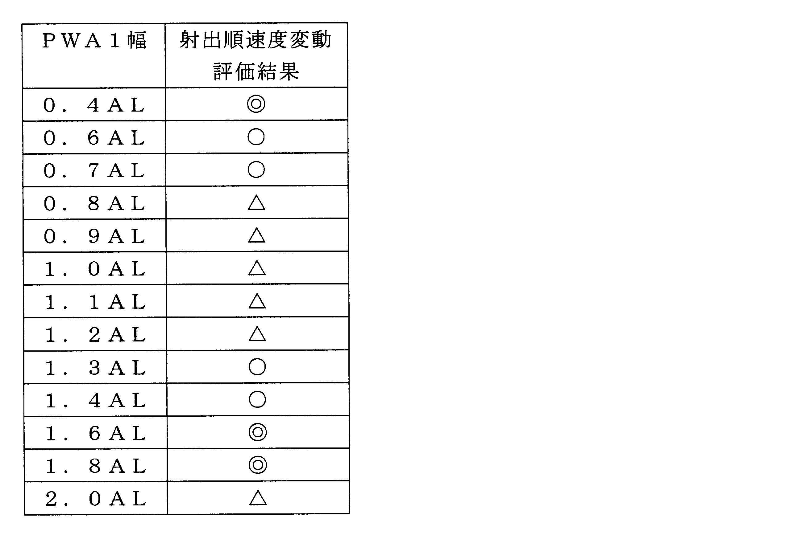
- the pulse width PWA1 of the first expansion pulse Pa1 in the first drive signal PA1 is set to 0.4 AL or more and 0.7 AL or less, or 1.3 AL or more and 1.8 AL or less. As a result, it is possible to suppress fluctuations in the droplet velocity of each droplet when the first drive signal PA1 is continuously driven in a short cycle while suppressing the influence of the satellite.
- the first drive signal PA1 is preferably a rectangular wave.
- the first expansion pulse Pa1, the first contraction pulse Pa2, the second expansion pulse Pa3, and the second contraction pulse Pa4 constituting the first drive signal PA1 are composed of rectangular waves as shown in FIG. Yes.
- the shear mode type head 3 can generate pressure waves in phase with respect to the application of a drive signal composed of a rectangular wave, it is possible to efficiently eject droplets and reduce the drive voltage. Further, it can be kept low. In general, a voltage is always applied to the head 3 regardless of whether it is ejected or not. Therefore, a low driving voltage is important for suppressing heat generation of the head 3 and ejecting droplets stably.
- the circuit configuration can be simplified as compared with the case of using a trapezoidal wave having a gradient wave.
- the voltage value of the first expansion pulse Pa1 and the voltage value of the second expansion pulse Pa3 are equal, and the voltage value of the first contraction pulse Pa2 and the second contraction pulse Pa4
- the voltage value is preferably equal. Since at least two power supplies are sufficient, the number of power supplies can be reduced. Thereby, the circuit configuration of the drive control unit 8 can be simplified.
- FIG. 6 is a diagram for explaining a second embodiment of the first drive signal in the present invention as the drive signal generated in the drive control unit 8.
- the first drive signal PA2 is a drive for discharging at least two droplets from the same nozzle 341 and combining them during flight immediately after discharge to form a large droplet.
- the first drive signal PA2 expands the volume of the channel 31 and contracts after a certain time
- the first contraction pulse Pa2 contracts the volume of the channel 31 and expands after a certain time.
- the second expansion pulse Pa3 that expands the volume of the channel 31 and contracts after a certain time
- the second contraction pulse Pa4 that contracts the volume of the channel 31 and expands after a certain time
- the volume of the channel 31 contracts
- the third contraction pulse Pa5 that is expanded after a predetermined time is provided in this order.
- the configuration of the waveform of the first drive signal PA2 shown in the present embodiment is that the first drive signal is only the point that the third contraction pulse Pa5 is added at an interval from the end of application of the second contraction pulse Pa4. It is different from PA1.
- the third contraction pulse Pa5 is a pulse that falls from the reference potential and rises to the reference potential after a certain time.
- the reference potential is set to 0 potential, but is not particularly limited.
- the pulse width PWA1 of the first expansion pulse Pa1 is set to 0.4 AL or more and 2.0 AL or less. Then, the second expansion pulse Pa3 and the second contraction pulse Pa4 are applied immediately after the first droplet is ejected from the nozzle 341 by the application of the first expansion pulse Pa1 and the first contraction pulse Pa2. The second droplet is ejected. Therefore, the same effect as that of the inkjet head 3 driving method and the inkjet recording apparatus 1 using the first drive signal PA1 is obtained.
- the pulse width PWA4 of the second contraction pulse Pa4 is set to 0.3 AL or more and 0.7 AL or less
- the pulse width PWA5 of the third contraction pulse Pa5 is set to 0.8 AL or more and 1.2 AL or less
- the third contraction pulse Pa5 is set to be applied with an interval of 0.3 AL or more and 0.7 AL or less from the end of application of the second contraction pulse Pa4, that is, with a rest period PWA6.
- the influence of the satellite can be further reduced by promoting the tearing of the tail associated with the main droplet.
- the pressure wave reverberation vibration in the channel 31 can also be effectively canceled by the third contraction pulse Pa5.
- the pulse width PWA4 of the second contraction pulse Pa4 is most preferably 0.5AL
- the pulse width PWA5 of the third contraction pulse Pa5 is most preferably 1AL
- the second contraction pulse Pa4 Most preferably, the third contraction pulse Pa5 is applied at an interval of 0.5 AL from the end of application.
- the pulse width PWA2 of the first contraction pulse Pa2 and the pulse width PWA3 of the second expansion pulse Pa3 are the first contraction pulse Pa2 and the second contraction pulse Pa2 in the first drive signal PA1. It is preferable to make the same as the expansion pulse Pa3.
- the volume of the channel 31B sandwiched between the partition walls 32B and 32C contracts from the expanded state, and the partition walls 32B and 32C are as shown in FIG. Return to the neutral state shown.
- the second contraction pulse Pa4 is subsequently applied to the drive electrode 36B without any rest period, the volume of the channel 31B immediately enters the contracted state shown in FIG.
- a large pressure is applied to the ink in the channel 31B, and further ink is ejected following the ink ejected by the first expansion pulse Pa1 and the first contraction pulse Pa2, and the first droplet is the same as in FIG.
- a large droplet 100 composed of 101 and the second droplet 102 is ejected.
- the volume of the channel 31B expands from the contracted state, and the partition walls 32B and 32C return to the neutral state shown in FIG.
- the ink meniscus is pulled back relatively early by the negative pressure generated in the channel 31.
- the tail of the ejected ink droplet is cut early, and the tail accompanying the ejected droplet 100 (main droplet) is shortened. Therefore, the influence of the satellite can be further reduced as compared with the case of the first drive signal PA1.
- the third contraction is performed at intervals of 0.3 AL to 0.7 AL.
- the pulse Pa5 is applied, the volume of the channel 31B is again brought into the contracted state shown in FIG. After a lapse of 0.8 AL or more and 1.2 AL or less, the volume of the channel 31B expands while positive pressure remains in the channel 31, and the partition walls 32B and 32C again become neutral as shown in FIG. Return to state. Thereby, a negative pressure is generated in the channel 31, and the pressure wave reverberation vibration is cancelled.
- the pulse width PWA1 of the first expansion pulse Pa1 is 0.4 AL or more and 0.7 AL or less, or 1.3 AL or more and 1 for the same reason as the first drive signal PA1. More preferably, it is set to 8 AL or less.
- the first drive signal PA2 is preferably a rectangular wave for the same reason as the first drive signal PA1.
- the first expansion pulse Pa1, the first contraction pulse Pa2, the second expansion pulse Pa3, the second contraction pulse Pa4, and the third contraction pulse Pa5 constituting the first drive signal PA2 are also as shown in FIG. It is composed of rectangular waves.
- the voltage value of the first expansion pulse Pa1 is equal to the voltage value of the second expansion pulse Pa3 for the same reason as the first drive signal PA1, and the first contraction is performed.
- the voltage value of the pulse Pa2, the voltage value of the second contraction pulse Pa4, and the voltage value of the third contraction pulse Pa5 are preferably equal.
- the voltage values of the first expansion pulse Pa1 and the second expansion pulse Pa3 are VH2, the first contraction pulse Pa2, the second contraction pulse Pa4, and
- 2/1.
- the first drive signal PA1 or PA2 described above is smaller and faster than the droplet 100 by the first drive signal PA1 or PA2.
- N is an integer of 0 or more
- first drive signals PA1 or PA2 and at least finally the second drive signal PB within one pixel period.
- the number of N is changed according to the image data. Note that one pixel period is a time interval for forming each pixel by dots by causing droplets ejected from the nozzle 341 to land on the medium 7.
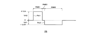
- FIG. 7 is a diagram for explaining a second drive signal in the present invention as a drive signal generated in the drive control unit 8.
- the second drive signal PB shown in FIG. 7 is a preferable example in the present invention, and is not limited to what is illustrated.
- the second drive signal PB has an expansion pulse Pb1 that expands the volume of the channel 31 and contracts after a certain time, and a contraction pulse Pb2 that contracts the volume of the channel 31 and expands after a certain time. .
- the expansion pulse Pb1 of the second drive signal PB shown in the present embodiment is a pulse that rises from the reference potential and falls to the reference potential after a certain time.
- the contraction pulse Pb2 is a pulse that falls from the reference potential and rises to the reference potential after a certain time.
- the reference potential is set to 0 potential, but is not particularly limited.
- a pause period PWB3 for maintaining the reference potential for a certain period is provided between the end of the expansion pulse Pb1 and the start of the contraction pulse Pb2. This is because, in relation to the first drive signal PA1 or PA2, it is avoided that the volume of the channel 31 suddenly changes from the expansion state due to the expansion pulse Pb1 to the contraction state due to the contraction pulse Pb2, so that the droplet velocity becomes too high. This is in order to avoid an excessive increase in the amount of discharged liquid droplets.
- the length of the pause period PWB3 the speed and volume of the liquid droplets ejected by the application of the second drive signal PB can be changed to the liquid droplets ejected by the first drive signal PA1 or PA2. Therefore, it can be easily adjusted. For this reason, this pause period PWB3 is preferably provided in the second drive signal PB.
- the expansion pulse Pb1 and the contraction pulse Pb2 constituting the second drive signal PB are also preferably rectangular waves as illustrated.
- the pulse width PWB1 of the expansion pulse Pb1 is preferably 0.8 AL to 1.2 AL, and the pulse width PWB2 of the contraction pulse Pb2 is preferably 1.8 AL to 2.2 AL.
- the droplets can be discharged efficiently. Further, if the pause period PWB3 becomes too long, the discharge efficiency is greatly reduced. Therefore, it is preferable to adjust it to 1/4 AL or less.
- FIG. 8 shows a conceptual diagram of droplets ejected when the second drive signal PB is applied.
- the channel 31B Since the pressure in the channel 31B is reversed every 1 AL, if the expansion pulse Pa1 is maintained for a period of 0.8 AL or more and 1.2 AL or less, the channel 31B turns to a positive pressure.
- the volume of the channel 31B sandwiched between the partition walls 32B and 32C contracts from the expanded state. Thereby, the partition walls 32B and 32C return to the neutral state shown in FIG. 4A (Release).
- a large pressure is applied to the ink in the channel 31 ⁇ / b> B, and the ink moves in the direction pushed out from the nozzle 341.
- the droplet 200 is a small droplet having a smaller droplet amount than the droplet 100 by the first drive signal PA1 or PA2 described above.
- the droplet 200 is discharged, no satellite is generated or even if it is generated, it is suppressed to a very small amount.
- the contracted state due to the contraction pulse Pb2 is restored when the pressure in the channel 31B turns positive after 1.8A or more and 2.2AL or less has passed.
- the volume of the channel 31B expands from the contracted state, and the partition walls 32B and 32C return to the neutral state of FIG.
- FIG. 9 shows an example of a driving method in the case where gradation expression is performed by combining the first driving signal PA1 and the second driving signal PB described above.
- Level 0 minimum gradation
- Level 5 six levels of gradation (maximum gradation) are expressed.
- Level 0 is a case where no drive signal is applied.
- the first drive signal PA2 can be expressed in gradation as described below in combination with the second drive signal PB in the same manner as the first drive signal PA1. .
- Each drive signal group expressing gradations from Level 1 to Level 5 can be stored in advance in the drive control unit 8 in association with each gradation.
- the drive control unit 8 selects a desired gradation in accordance with the image data, calls a corresponding drive signal group, and then applies the drive signal group to the head 3.
- the number of droplets ejected from the same nozzle 341 is changed by applying the second drive signal PB at least at the end of one pixel period T except for Level 0.
- the gradation can be expressed by changing the number N to which the first drive signal PA1 is applied by an integer equal to or greater than 0 and forming pixels by dots formed of droplets on the medium 7.
- the plurality of liquid droplets are united during flight, so that a dot composed of one united liquid droplet is formed on the medium 7.
- Pixels can be formed.
- a pixel can also be formed by a dot consisting of an aggregate of a plurality of dots by landing a plurality of droplets on the medium 7 so as to overlap each other.
- the first drive signal PA1 is a drive signal for ejecting a droplet 100 that is relatively larger than the droplet 200 generated by the second drive signal PB. For this reason, when one or more first drive signals PA1 are applied within one pixel period T, mainly large dots are formed, which contributes to expressing dark gradation. Further, as described above, the droplet 100 is relatively slow as compared with the droplet 200, and the generated satellite is captured by the droplet discharged later within the same pixel period T. Therefore, the satellite is not a problem that degrades the image quality.
- the droplet 100 is a large droplet having a larger droplet amount than the droplet 200.
- the first droplet 101 having a low droplet velocity and the second droplet 102 having a large droplet velocity are combined, compared with the case where one large droplet having the same droplet amount is ejected from the nozzle 341.
- the droplet velocity is slow. According to the present embodiment, the droplet 100 is slower than the droplet 200.
- the droplet velocity of the droplet 200 is preferably adjusted to be smaller than the droplet velocity of the second droplet 102 of the droplet 100.
- the amount of satellite of the droplet 100 depends on the droplet velocity of the second droplet 102, and the droplet velocity of the droplet 200 is adjusted to be smaller than the droplet velocity of the second droplet 102 of the droplet 100.
- the amount of satellite of the droplet 200 can be suppressed.
- the second drive signal PB is always applied at the end of one pixel period T, so that a droplet 200 that is relatively smaller than the droplet 100 generated by the first drive signal PA1 is generated. As it is discharged, no satellite is generated or suppressed.
- TA is a drive cycle of the first drive signal PA1 within one pixel cycle T
- TB is a drive cycle of the second drive signal PB within one pixel cycle T.
- the first drive signal PA1 is applied with a predetermined pause period T1 between the subsequent drive signals and the next one pixel period from the end of the application of one second drive signal PB applied last.
- a predetermined pause period T2 is set before the start of T.
- the pause period T1 is preferably 2AL or less, and the influence of residual vibration after droplet ejection is suppressed, and subsequent droplet ejection is stabilized. From the viewpoint, it is preferable that the suspension period T2 is 1.5 AL or more.
- one second drive signal PB is always applied at least at the end of one pixel period T, except for Level0. Therefore, it does not prevent the application of one or more second drive signals PB before the second drive signal PB applied last in one pixel period T.
- the second drive signal PB may be applied first in one pixel period T, but the second drive signal PB to be applied last is the rest period PWB3 of the second drive signal PB.
- the first ejected droplet is slower in speed than the last ejected droplet to improve the landing elasticity.
- the number N of the first drive signals PA1 may be an integer greater than or equal to 0 and is not limited to the number shown in the figure.
- the second drive signal PB is always at the end of one pixel period T. Is applied. For this reason, satellites are suppressed when any gradation is expressed. Note that the second drive signal PB to be applied last is applied at the same timing within one pixel period T, as shown in the figure, in any gradation for ejecting droplets.
- the second drive signal PB is preferably a drive signal for forming the smallest droplet among a plurality of drive signals arranged in time series within one pixel period T. This can further enhance the effect of suppressing satellites.
- the second drive signal PB is a drive for forming a droplet having the smallest droplet speed and a fast droplet velocity among a plurality of drive signals arranged in time series within one pixel period T.
- a signal is preferable from the viewpoint of enhancing the effect of suppressing satellites and the effect of suppressing landing position deviation.
- a large droplet can also be ejected by using a drive signal having a DRR (Draw-Release-Reinforce) waveform similar to the second drive signal PB and increasing its pulse width.
- DRR Digital-Release-Reinforce
- the drive signal has a long period, many droplets cannot be ejected within a limited time within one pixel period T as in the case of expressing the maximum gradation.
- the first drive signal PA1 it is possible to discharge a relatively low-speed large droplet 100 in a short period, and thus more droplets can be obtained within a limited time within one pixel period T. Can be discharged. Therefore, by changing the number N of the first drive signals PA1 according to the image data, it is possible to realize a wide gradation expression from the minimum gradation to the maximum gradation.
- the diameter of the droplet 200 ejected by the second drive signal PB is preferably smaller than the diameter of the nozzle 341.
- the diameter of the nozzle refers to the diameter when the shape of the opening at the tip of the discharge direction of the nozzle is circular, and when not, it is the diameter of the circle when the area of the opening is replaced with the same circle. .
- the diameter of the droplet refers to the diameter when the droplet is spherical, and when the droplet is not spherical, it is the diameter of the sphere when the volume is replaced with the same sphere.
- the diameter of the droplet 100 ejected by the first drive signal PA1 or PA2 is larger than the diameter of the nozzle 341.
- gradation can be expressed by forming as large a dot as possible on the medium 7.
- the diameter of the droplet 100 ejected by the first drive signal PA1 or PA2 is a diameter in a state where the first droplet 101 and the second droplet 102 are integrated into one large droplet. It is.
- the diameter of the droplet 200 ejected by the second drive signal PB is smaller than the diameter of the nozzle 341
- the diameter of the droplet 100 ejected by the first drive signal PA1 or PA2 is the diameter of the nozzle 341. It is more preferable that it is larger than that.
- the droplet amount of a droplet ejected by the first drive signal PA1 or PA2 is MA and the droplet amount of a droplet ejected by the second drive signal PB is MB
- MA ⁇ MB ⁇ 1. .5 is preferable. Accordingly, it is possible to form pixels composed of as large dots as possible on the medium 7 at the maximum gradation while effectively suppressing satellites.
- the drive cycle TA of the first drive signal PA1 or PA2 and the drive cycle TB of the second drive signal PB within one pixel cycle T are used for expressing gradation on the medium 7 while suppressing satellites.
- TA TB can be set, but TA ⁇ TB is preferable. Since the large droplet 100 by the first drive signal PA1 or PA2 is relatively slow, by TA ⁇ TB, it is determined by the first drive signal PA1 or PA2 within one pixel period T at dark gradation. A large number of large droplets 100 can be produced at high speed in a short time.
- the pulse Pa3 and the expansion pulse Pb1) have constant wave heights, and the first drive signal PA1 or PA2 and the second drive signal PB applied to the drive electrodes of the channel 31 corresponding to the same nozzle 341, respectively.
- the contraction pulses (first contraction pulse Pa2, second contraction pulse Pa4, second contraction pulse Pa5, contraction pulse Pb2,) preferably have a constant wave height as shown in FIG. Since the + Von voltage value and the ⁇ Voff voltage value of each drive signal PA1 or PA2 and PB can be made constant, the configuration of the drive control unit 8 can be further simplified.
- the droplets 100 ejected by each first drive signal PA1 or PA2 have the same speed. It may be a different speed.
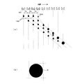
- FIG. 10 shows a plan view of the flying state with the passage of time of 100 and 200 and the dots D formed on the medium 7 thereby.
- each droplet 100 is set to the same speed, as shown in FIG. 10A, the three droplets 100 continuously ejected within one pixel period T fly at a constant velocity.
- the droplet 200 catches up and coalesces because it is faster than the droplet 100 ejected immediately before. Since the combined droplet is faster than the immediately preceding droplet 100, the combined droplet further catches up with the immediately preceding droplet 100 and merges so that all the droplets 100, 200 are combined during the flight. Do it.
- a pixel composed of dots D by one droplet shown in FIG. 10B is formed on the medium 7.
- the droplet velocity of the droplet 100 can be adjusted by the pulse width PWA1 of the first expansion pulse Pa1. Accordingly, when the droplet speeds of the respective droplets 100 are made different, it can be performed by adjusting the pulse width PWA1 of the first expansion pulse Pa1 within a range of 0.4 AL or more and 2.0 AL or less.
- the first drive signal PA1 in order of decreasing pulse width PWA1 of the first expansion pulse Pa1 within one pixel period T. Since each droplet 100 ejected thereby has a higher speed than the droplet 100 ejected later, it is effective when the droplets 100 are surely united during flight.
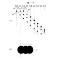
- a plan view of the flying state of the droplets 100 and 200 with the passage of time when the speed is increased by about 100 and the dots D formed on the medium 7 by the flying state is shown.
- the first drive signal PA1 can be applied in the order of increasing pulse width PWA1 of the first expansion pulse Pa1 of the first drive signal PA1, that is, in order of increasing droplet velocity.
- a plan view of the flying state of the droplets 100 and 200 with the passage of time when the speed is increased by about 100 and the dots D formed on the medium 7 by the flying state is shown.
- the dot D as shown in FIG. 12B has no influence at all in the application in which the application amount is obtained by using only a large dot as in the case of recording a solid image.
- the image quality is not greatly affected, but there is a concern that the landing position is slightly shifted every time the droplet amount is different.
- the droplet velocity changes depending on the timing at which the ejected droplets coalesce, and landing position deviation for each gradation is a problem. It may become.
- the droplet 100 ejected by the first drive signal PA1 or PA2 and the droplet 200 ejected by the second drive signal PB come together during flight, the energy of the droplet 200 is lost. Affects droplet velocity. This is because the droplet 100 is larger than the droplet 200. Therefore, there is a possibility that the landing position is slightly different between the case where only one droplet 200 is discharged and the case where a plurality of droplets 100 are discharged in addition to the droplet 200.
- the droplet velocity of the droplet 100 by the first drive signal PA1 or PA2 is VA
- the droplet amount is MA
- the droplet velocity of the droplet 200 by the second drive signal PB is VB
- the droplet amount is MB.
- the effect of the temporary break depends on the ratio of the momentum of the large droplet to the small droplet (MB ⁇ VB) / (MA ⁇ VA)
- the impact on the landing is the gap to the media 7 (nozzle of the head 3).
- the number N of the first drive signals PA1 or PA2 increases and N ⁇ 3
- the final number of coalescence tends to increase, so the problem of landing position deviation becomes more significant than the others.
- a signal having a + Von expansion pulse and a ⁇ Voff contraction pulse is used as each drive signal, but the present invention is not limited to this.
- the deformation of the partition wall 32 occurs due to a voltage difference between two drive electrodes provided so as to sandwich the partition wall 32. Therefore, when ejection is performed by the first drive signal PA1 from the channel 31B illustrated in FIG. ), A + Von first expansion pulse Pa1 and a second expansion pulse Pa3 are applied to the drive electrode 36B in the channel 31B, which is an ejection channel, and the drive electrodes 36A and 36C of the adjacent channels 31A and 31C are applied. In addition, even if the first contraction pulse Pa2 of + Voff is applied, the same driving can be performed.
- the drive electrode 36B in the channel 31B which is the ejection channel, is applied to + Von.
- the first expansion pulse Pa1 and the second expansion pulse Pa3 are applied, and the + Voff first contraction pulse Pa2, the second contraction pulse Pa4, and the third contraction pulse Pa4 are applied to the drive electrodes 36A and 36C of the adjacent channels 31A and 31C. Even if the contraction pulse Pa5 is applied, it can be driven similarly.
- the drive electrode 36B in the channel 31B which is the discharge channel, is applied to + Von.
- a first expansion pulse Pb1 and a second expansion pulse Pb3 are applied, and a + Voff first contraction pulse Pb2 and a second contraction pulse Pb4 are applied to the drive electrodes 36A and 36C of the adjacent channels 31A and 31C.
- each drive signal can be configured with only a positive voltage. It can be simplified.
- the head 3 is exemplified as one in which the partition wall 32 between adjacent channels 31 and 31 is shear-deformed, but the pressure generating means in which the upper wall or the lower wall of the channel is configured by a piezoelectric element such as PZT.
- the upper wall or the lower wall may be subjected to shear deformation.
- the ink jet head in the present invention is not limited to the shear mode type.
- As the ink UV curable ink was used at 40 ° C. The viscosity of the ink at this time was 0.01 Pa ⁇ s.
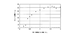
- the rectangular wave first drive signal PA1 shown in FIG. 3 is used as the first drive signal, and the pulse width PWA1 of the first expansion pulse Pa1 is changed from 0.2 AL to 2 AL as shown in the graph of FIG. The amount of droplets ejected at each time was measured.
- the pulse width PWA2 of the first contraction pulse Pa2 0.5AL
- the pulse width PWA3 1AL of the second expansion pulse Pa3
- the pulse width PWA4 2AL of the second contraction pulse Pa4
- the driving cycle 7AL.
- the droplet velocity was 6 m / s.
- Example 2 The satellite generation state of each droplet discharged in Example 1 was observed.
- the state of satellite generation was measured by measuring the separation distance from the main droplet to the satellite at a position flying 1.0 mm from the nozzle, and evaluating the length according to the following criteria. The longer the separation distance, the more the satellites land from the main droplets, affecting the degradation of image quality. The results are shown in Table 1.
- Inkjet recording apparatus 2 Transport mechanism 21: Transport roller 22: Transport roller pair 23: Transport motor 3: Inkjet head 30: Channel substrate 31: Channel 32: Partition wall 321: Upper wall portion 322: Lower wall portion 33: Cover substrate 331: Common flow path 34: Nozzle plate 341: Nozzle 35: Plate 351: Ink supply port 352: Ink supply pipe 4: Guide rail 5: Carriage 6: Flexible cable 7: Media 71: Recording surface 8: Drive control unit 100: Droplet 101: First droplet 100: Second droplet 200: Droplet D: Dot PA1, PA2: First drive signal Pa1: First expansion pulse Pa2: First contraction pulse Pa3: Second expansion Pulse Pa4: Second contraction pulse Pa5: Third contraction pulse PWA PWA5: Pulse width PWA6: Pause period PB: Second drive signal Pb1: Expansion pulse Pb2: Contraction pulse PWB1, PWB2: Pulse width PWB3: Pause period T: Pixel period TA: Drive period of the first drive signal TB: Drive
Landscapes
- Particle Formation And Scattering Control In Inkjet Printers (AREA)
Abstract
Description
同一の前記ノズルから少なくとも2つの液滴を吐出させ、吐出直後に合体させて大液滴を形成する際、前記駆動信号として第1の駆動信号を印加するものであり、
前記第1の駆動信号は、前記圧力室の容積を膨張させ、一定時間後に収縮させる第1の膨張パルスと、前記圧力室の容積を収縮させ、一定時間後に膨張させる第1の収縮パルスと、前記圧力室の容積を膨張させ、一定時間後に収縮させる第2の膨張パルスと、前記圧力室の容積を収縮させ、一定時間後に膨張させる第2の収縮パルスとをこの順に有し、
前記第1の膨張パルス及び前記第1の収縮パルスの印加により前記ノズルから1つ目の液滴を吐出させると共に、前記第2の膨張パルス及び前記第2の収縮パルスの印加により2つ目の液滴を吐出させ、
且つ、前記第1の膨張パルスのパルス幅は、0.4AL以上2.0AL以下(但し、ALは前記圧力室における圧力波の音響的共振周期の1/2)であるインクジェットヘッドの駆動方法。
前記圧力発生手段を駆動させる駆動信号を出力する駆動制御手段とを備えるインクジェット記録装置において、
前記駆動信号は、同一の前記ノズルから少なくとも2つの液滴を吐出させ、吐出直後に合体させて大液滴を形成する第1の駆動信号を含み、
前記第1の駆動信号は、前記圧力室の容積を膨張させ、一定時間後に収縮させる第1の膨張パルスと、前記圧力室の容積を収縮させ、一定時間後に膨張させる第1の収縮パルスと、前記圧力室の容積を膨張させ、一定時間後に収縮させる第2の膨張パルスと、前記圧力室の容積を収縮させ、一定時間後に膨張させる第2の収縮パルスとをこの順に有し、
前記第1の膨張パルス及び前記第1の収縮パルスの印加により前記ノズルから1つ目の液滴を吐出させると共に、前記第2の膨張パルス及び前記第2の収縮パルスの印加により2つ目の液滴を吐出させ、
且つ、前記第1の膨張パルスのパルス幅は、0.4AL以上2.0AL以下(但し、ALは前記圧力室における圧力波の音響的共振周期の1/2)であるインクジェット記録装置。
図2に示すせん断モード型のインクジェットヘッド(ノズルの直径=24μm、AL=3.7μs)を用意した。インクにはUV硬化型のインクを40℃で使用した。このときのインクの粘度は0.01Pa・sであった。
図7に示す第2の駆動信号PBにおいて、膨張パルスPb1のパルス幅PWB1=1AL、収縮パルスPb2のパルス幅PWB2=2AL、休止期間PWB3=0とした一般的なDRR波形からなる駆動信号を用いて、同じく6m/sの液滴速度で液滴を吐出させたところ、液滴量は6.7ngであった。
実施例1において吐出された各液滴のサテライトの発生状況を観察した。サテライトの発生状況は、ノズルから1.0mm飛翔した位置における主滴からサテライトまでの分離距離を計測し、その長短を以下の基準によって評価した。分離距離が長い程、サテライトは主滴からずれて着弾し、画像品質の低下に影響する。その結果を表1に示す。
○:普通
△:やや長い
×:長い

実施例1と同一の第1の駆動信号PA1を用いて、駆動周期=7ALとして連続して10発の液滴を吐出させ、そのときの1発目から10発目の各液滴の射出順の速度変化を求め、以下の基準に従って評価した。
○:10%以上、15%未満
△:15%以上、25%未満
×:25%以上
2:搬送機構
21:搬送ローラー
22:搬送ローラー対
23:搬送モーター
3:インクジェットヘッド
30:チャネル基板
31:チャネル
32:隔壁
321:上壁部
322:下壁部
33:カバー基板
331:共通流路
34:ノズルプレート
341:ノズル
35:プレート
351:インク供給口
352:インク供給管
4:ガイドレール
5:キャリッジ
6:フレキシブルケーブル
7:メディア
71:記録面
8:駆動制御部
100:液滴
101:第1液滴
100:第2液滴
200:液滴
D:ドット
PA1、PA2:第1の駆動信号
Pa1:第1の膨張パルス
Pa2:第1の収縮パルス
Pa3:第2の膨張パルス
Pa4:第2の収縮パルス
Pa5:第3の収縮パルス
PWA1~PWA5:パルス幅
PWA6:休止期間
PB:第2の駆動信号
Pb1:膨張パルス
Pb2:収縮パルス
PWB1、PWB2:パルス幅
PWB3:休止期間
T:画素周期
TA:第1の駆動信号の駆動周期
TB:第2の駆動信号の駆動周期
T1、T2:休止期間
Claims (26)
- 圧力室の容積を膨張又は収縮させる圧力発生手段に駆動信号を印加し、該圧力発生手段を駆動させることによって前記圧力室内の液体に圧力を付与し、ノズルから液滴を吐出させるインクジェットヘッドの駆動方法において、
同一の前記ノズルから少なくとも2つの液滴を吐出させ、吐出直後に合体させて大液滴を形成する際、前記駆動信号として第1の駆動信号を印加するものであり、
前記第1の駆動信号は、前記圧力室の容積を膨張させ、一定時間後に収縮させる第1の膨張パルスと、前記圧力室の容積を収縮させ、一定時間後に膨張させる第1の収縮パルスと、前記圧力室の容積を膨張させ、一定時間後に収縮させる第2の膨張パルスと、前記圧力室の容積を収縮させ、一定時間後に膨張させる第2の収縮パルスとをこの順に有し、
前記第1の膨張パルス及び前記第1の収縮パルスの印加により前記ノズルから1つ目の液滴を吐出させると共に、前記第2の膨張パルス及び前記第2の収縮パルスの印加により2つ目の液滴を吐出させ、
且つ、前記第1の膨張パルスのパルス幅は、0.4AL以上2.0AL以下(但し、ALは前記圧力室における圧力波の音響的共振周期の1/2)であるインクジェットヘッドの駆動方法。 - 前記第1の駆動信号における前記第1の収縮パルスのパルス幅は、0.4AL以上0.7AL以下であり、前記第2の膨張パルスのパルス幅は、0.8AL以上1.2AL以下であり、前記第2の収縮パルスのパルス幅は、1.8AL以上2.2AL以下である請求項1記載のインクジェットヘッドの駆動方法。
- 前記第1の駆動信号における前記第1の膨張パルスの電圧値と前記第2の膨張パルスの電圧値が等しく、且つ、前記第1の収縮パルスの電圧値と前記第2の収縮パルスの電圧値が等しい請求項2記載のインクジェットヘッドの駆動方法。
- 前記第1の駆動信号における前記第1の膨張パルス及び前記第2の膨張パルスの電圧値をVH2、前記第1の収縮パルス及び前記第2の収縮パルスの電圧値をVH1としたとき、|VH2|/|VH1|=2/1である請求項3記載のインクジェットヘッドの駆動方法。
- 前記第1の駆動信号は、前記圧力室の容積を収縮させ、一定時間後に膨張させる第3の収縮パルスをさらに有し、
前記第2の収縮パルスのパルス幅は、0.3AL以上0.7AL以下であり、
前記第3の収縮パルスのパルス幅は、0.8AL以上1.2AL以下であり、
前記第2の収縮パルスの印加終了から0.3AL以上0.7AL以下の間隔をおいて前記第3の収縮パルスを印加する請求項1記載のインクジェットヘッドの駆動方法。 - 前記第1の駆動信号における前記第1の収縮パルスのパルス幅は、0.4AL以上0.7AL以下であり、前記第2の膨張パルスのパルス幅は、0.8AL以上1.2AL以下である請求項5記載のインクジェットヘッドの駆動方法。
- 前記第1の駆動信号における前記第1の膨張パルスの電圧値と前記第2の膨張パルスの電圧値が等しく、且つ、前記第1の収縮パルスの電圧値と前記第2の収縮パルスと前記第3の収縮パルスの電圧値が等しい請求項5又は6記載のインクジェットヘッドの駆動方法。
- 前記第1の駆動信号における前記第1の膨張パルス及び前記第2の膨張パルスの電圧値をVH2、前記第1の収縮パルス、前記第2の収縮パルス及び前記第3の収縮パルスの電圧値をVH1としたとき、|VH2|/|VH1|=2/1である請求項7記載のインクジェットヘッドの駆動方法。
- 前記第1の駆動信号における前記第1の膨張パルスのパルス幅は、0.4AL以上0.7AL以下、又は、1.3AL以上1.8AL以下である請求項1~8のいずれかに記載のインクジェットヘッドの駆動方法。
- 前記第1の駆動信号は矩形波である請求項1~9のいずれかに記載のインクジェットヘッドの駆動方法。
- 前記第1の駆動信号による液滴よりも相対的に高速で小さな液滴を形成する際、前記駆動信号として第2の駆動信号を印加するものであり、
前記第2の駆動信号は、前記圧力室の容積を膨張させ、一定時間後に収縮させる膨張パルスと、前記圧力室の容積を収縮させ、一定時間後に膨張させる収縮パルスと、前記膨張パルスと前記収縮パルスとの間を繋ぐ休止期間とを有し、
1画素周期内で、N個(Nは0以上の整数)の前記第1の駆動信号と、少なくとも最後に前記第2の駆動信号とを印加し、且つ、画像データに応じて、前記Nの個数を変化させることにより階調表現を行う請求項1~10のいずれかに記載のインクジェットヘッドの駆動方法。 - 前記第2の駆動信号における前記膨張パルスのパルス幅は、0.8AL以上1.2AL以下であり、前記収縮パルスのパルス幅は、1.8AL以上2.2AL以下であり、前記休止期間は、1/4AL以下である請求項11記載のインクジェットヘッドの駆動方法。
- 前記インクジェットヘッドは、せん断モード型のインクジェットヘッドである請求項1~12のいずれかに記載のインクジェットヘッドの駆動方法。
- 圧力発生手段の駆動によって圧力室内の液体に吐出のための圧力を付与し、ノズルから液滴を吐出させるインクジェットヘッドと、
前記圧力発生手段を駆動させる駆動信号を出力する駆動制御手段とを備えるインクジェット記録装置において、
前記駆動信号は、同一の前記ノズルから少なくとも2つの液滴を吐出させ、吐出直後に合体させて大液滴を形成する第1の駆動信号を含み、
前記第1の駆動信号は、前記圧力室の容積を膨張させ、一定時間後に収縮させる第1の膨張パルスと、前記圧力室の容積を収縮させ、一定時間後に膨張させる第1の収縮パルスと、前記圧力室の容積を膨張させ、一定時間後に収縮させる第2の膨張パルスと、前記圧力室の容積を収縮させ、一定時間後に膨張させる第2の収縮パルスとをこの順に有し、
前記第1の膨張パルス及び前記第1の収縮パルスの印加により前記ノズルから1つ目の液滴を吐出させると共に、前記第2の膨張パルス及び前記第2の収縮パルスの印加により2つ目の液滴を吐出させ、
且つ、前記第1の膨張パルスのパルス幅は、0.4AL以上2.0AL以下(但し、ALは前記圧力室における圧力波の音響的共振周期の1/2)であるインクジェット記録装置。 - 前記第1の駆動信号における前記第1の収縮パルスのパルス幅は、0.4AL以上0.7AL以下であり、前記第2の膨張パルスのパルス幅は、0.8AL以上1.2AL以下であり、前記第2の収縮パルスのパルス幅は、1.8AL以上2.2AL以下である請求項14記載のインクジェット記録装置。
- 前記第1の駆動信号における前記第1の膨張パルスの電圧値と前記第2の膨張パルスの電圧値が等しく、且つ、前記第1の収縮パルスの電圧値と前記第2の収縮パルスの電圧値が等しい請求項15記載のインクジェット記録装置。
- 前記第1の駆動信号における前記第1の膨張パルス及び前記第2の膨張パルスの電圧値をVH2、前記第1の収縮パルス及び前記第2の収縮パルスの電圧値をVH1としたとき、|VH2|/|VH1|=2/1である請求項16記載のインクジェット記録装置。
- 前記第1の駆動信号は、前記圧力室の容積を収縮させ、一定時間後に膨張させる第3の収縮パルスをさらに有し、
前記第2の収縮パルスのパルス幅は、0.3AL以上0.7AL以下であり、
第3の収縮パルスのパルス幅は、0.8AL以上1.2AL以下であり、
前記第2の収縮パルスの印加終了から0.3AL以上0.7AL以下の間隔をおいて前記第3の収縮パルスを印加する請求項14記載のインクジェット記録装置。 - 前記第1の駆動信号における前記第1の収縮パルスのパルス幅は、0.4AL以上0.7AL以下であり、前記第2の膨張パルスのパルス幅は、0.8AL以上1.2AL以下である請求項18記載のインクジェット記録装置。
- 前記第1の駆動信号における前記第1の膨張パルスの電圧値と前記第2の膨張パルスの電圧値が等しく、且つ、前記第1の収縮パルスの電圧値と前記第2の収縮パルスと前記第3の収縮パルスの電圧値が等しい請求項18又は19記載のインクジェット記録装置。
- 前記第1の駆動信号における前記第1の膨張パルス及び前記第2の膨張パルスの電圧値をVH2、前記第1の収縮パルス、前記第2の収縮パルス及び前記第3の収縮パルスの電圧値をVH1としたとき、|VH2|/|VH1|=2/1である請求項20記載のインクジェット記録装置。
- 前記第1の駆動信号における前記第1の膨張パルスのパルス幅は、0.4AL以上0.7AL以下、又は、1.3AL以上1.8AL以下である請求項14~21のいずれかに記載のインクジェット記録装置。
- 前記第1の駆動信号は矩形波である請求項14~22のいずれかに記載のインクジェット記録装置。
- 前記第1の駆動信号による液滴よりも相対的に高速で小さな液滴を形成する際、前記駆動信号として第2の駆動信号を印加するものであり、
前記第2の駆動信号は、前記圧力室の容積を膨張させ、一定時間後に収縮させる膨張パルスと、前記圧力室の容積を収縮させ、一定時間後に膨張させる収縮パルスと、前記膨張パルスと前記収縮パルスとの間を繋ぐ休止期間とを有し、
1画素周期内で、N個(Nは0以上の整数)の前記第1の駆動信号と、少なくとも最後に前記第2の駆動信号とを印加し、且つ、画像データに応じて、前記Nの個数を変化させることにより階調表現を行う請求項14~23のいずれかに記載のインクジェット記録装置。 - 前記第2の駆動信号における前記膨張パルスのパルス幅は、0.8AL以上1.2AL以下であり、前記収縮パルスのパルス幅は、1.8AL以上2.2AL以下であり、前記休止期間は、1/4AL以下である請求項24記載のインクジェット記録装置。
- 前記インクジェットヘッドは、せん断モード型のインクジェットヘッドである請求項14~25のいずれかに記載のインクジェット記録装置。
Priority Applications (3)
| Application Number | Priority Date | Filing Date | Title |
|---|---|---|---|
| JP2016511901A JP6497383B2 (ja) | 2014-03-31 | 2015-03-30 | インクジェットヘッドの駆動方法及びインクジェット記録装置 |
| EP15774244.6A EP3127704B1 (en) | 2014-03-31 | 2015-03-30 | Inkjet head driving method and inkjet printing apparatus |
| CN201580027118.6A CN106457824B (zh) | 2014-03-31 | 2015-03-30 | 喷墨头的驱动方法以及喷墨记录装置 |
Applications Claiming Priority (2)
| Application Number | Priority Date | Filing Date | Title |
|---|---|---|---|
| JP2014073969 | 2014-03-31 | ||
| JP2014-073969 | 2014-03-31 |
Publications (1)
| Publication Number | Publication Date |
|---|---|
| WO2015152185A1 true WO2015152185A1 (ja) | 2015-10-08 |
Family
ID=54240506
Family Applications (1)
| Application Number | Title | Priority Date | Filing Date |
|---|---|---|---|
| PCT/JP2015/060017 Ceased WO2015152185A1 (ja) | 2014-03-31 | 2015-03-30 | インクジェットヘッドの駆動方法及びインクジェット記録装置 |
Country Status (4)
| Country | Link |
|---|---|
| EP (1) | EP3127704B1 (ja) |
| JP (1) | JP6497383B2 (ja) |
| CN (1) | CN106457824B (ja) |
| WO (1) | WO2015152185A1 (ja) |
Cited By (6)
| Publication number | Priority date | Publication date | Assignee | Title |
|---|---|---|---|---|
| WO2017099021A1 (ja) * | 2015-12-08 | 2017-06-15 | コニカミノルタ株式会社 | インクジェット記録装置、インクジェットヘッドの駆動方法及び駆動波形の設計方法 |
| JP2018015974A (ja) * | 2016-07-27 | 2018-02-01 | コニカミノルタ株式会社 | インクジェット記録装置及びインクジェット記録方法 |
| WO2018043074A1 (ja) * | 2016-08-31 | 2018-03-08 | コニカミノルタ株式会社 | インクジェット記録装置及びインクジェット記録方法 |
| EP3815904A1 (en) | 2019-11-01 | 2021-05-05 | SII Printek Inc. | Liquid jet head and liquid jet recording device |
| EP3815907A1 (en) | 2019-11-01 | 2021-05-05 | SII Printek Inc. | Liquid jet head and liquid jet recording device |
| JP2023028785A (ja) * | 2021-08-20 | 2023-03-03 | 東芝テック株式会社 | インクジェットヘッド及びインクジェット記録装置 |
Families Citing this family (6)
| Publication number | Priority date | Publication date | Assignee | Title |
|---|---|---|---|---|
| JP2020055214A (ja) * | 2018-10-02 | 2020-04-09 | 東芝テック株式会社 | 液体吐出ヘッド及びプリンタ |
| JP7097511B2 (ja) | 2018-11-15 | 2022-07-07 | ランダ コーポレイション リミテッド | インクジェット印刷のためのパルス波形 |
| JP7355561B2 (ja) * | 2019-09-04 | 2023-10-03 | 東芝テック株式会社 | 液体吐出ヘッド及び液体吐出装置 |
| JP7596081B2 (ja) * | 2020-05-20 | 2024-12-09 | 理想テクノロジーズ株式会社 | 液体吐出ヘッド及び液体吐出装置 |
| JP7506527B2 (ja) * | 2020-05-26 | 2024-06-26 | 東芝テック株式会社 | 液体吐出ヘッド |
| JP2024140406A (ja) * | 2023-03-28 | 2024-10-10 | 理想テクノロジーズ株式会社 | 駆動装置及び液体吐出装置 |
Citations (6)
| Publication number | Priority date | Publication date | Assignee | Title |
|---|---|---|---|---|
| JP2000085158A (ja) * | 1998-09-11 | 2000-03-28 | Matsushita Electric Ind Co Ltd | インクジェット記録装置及び記録方法 |
| JP2001301207A (ja) * | 2000-04-26 | 2001-10-30 | Konica Corp | インク滴噴射装置 |
| JP2007152873A (ja) * | 2005-12-08 | 2007-06-21 | Konica Minolta Holdings Inc | インクジェット記録方法及びそれに用いるインクジェット記録用インク |
| JP2011031442A (ja) * | 2009-07-31 | 2011-02-17 | Riso Kagaku Corp | インクジェット記録装置 |
| JP2011037260A (ja) * | 2009-07-17 | 2011-02-24 | Konica Minolta Ij Technologies Inc | インクジェット記録装置 |
| JP2015051585A (ja) * | 2013-09-06 | 2015-03-19 | 株式会社東芝 | インクジェットヘッドの駆動装置、及び駆動方法 |
Family Cites Families (5)
| Publication number | Priority date | Publication date | Assignee | Title |
|---|---|---|---|---|
| US6513915B1 (en) * | 1998-10-27 | 2003-02-04 | Matsushita Electric Industrial Co., Ltd. | Variable dot ink-jet printer |
| JP5440392B2 (ja) * | 2010-05-31 | 2014-03-12 | コニカミノルタ株式会社 | インクジェット記録装置 |
| US8328309B2 (en) * | 2010-06-01 | 2012-12-11 | Kabushiki Kaisha Toshiba | Ink jet head and method of driving the same |
| JP5867072B2 (ja) * | 2011-12-27 | 2016-02-24 | コニカミノルタ株式会社 | 液滴射出装置及び液滴射出装置の駆動方法 |
| JP5861513B2 (ja) * | 2012-03-14 | 2016-02-16 | コニカミノルタ株式会社 | インクジェット記録装置 |
-
2015
- 2015-03-30 JP JP2016511901A patent/JP6497383B2/ja active Active
- 2015-03-30 WO PCT/JP2015/060017 patent/WO2015152185A1/ja not_active Ceased
- 2015-03-30 EP EP15774244.6A patent/EP3127704B1/en active Active
- 2015-03-30 CN CN201580027118.6A patent/CN106457824B/zh active Active
Patent Citations (6)
| Publication number | Priority date | Publication date | Assignee | Title |
|---|---|---|---|---|
| JP2000085158A (ja) * | 1998-09-11 | 2000-03-28 | Matsushita Electric Ind Co Ltd | インクジェット記録装置及び記録方法 |
| JP2001301207A (ja) * | 2000-04-26 | 2001-10-30 | Konica Corp | インク滴噴射装置 |
| JP2007152873A (ja) * | 2005-12-08 | 2007-06-21 | Konica Minolta Holdings Inc | インクジェット記録方法及びそれに用いるインクジェット記録用インク |
| JP2011037260A (ja) * | 2009-07-17 | 2011-02-24 | Konica Minolta Ij Technologies Inc | インクジェット記録装置 |
| JP2011031442A (ja) * | 2009-07-31 | 2011-02-17 | Riso Kagaku Corp | インクジェット記録装置 |
| JP2015051585A (ja) * | 2013-09-06 | 2015-03-19 | 株式会社東芝 | インクジェットヘッドの駆動装置、及び駆動方法 |
Cited By (14)
| Publication number | Priority date | Publication date | Assignee | Title |
|---|---|---|---|---|
| CN108367567B (zh) * | 2015-12-08 | 2020-05-29 | 柯尼卡美能达株式会社 | 喷墨记录装置、喷墨头的驱动方法以及驱动波形的设计方法 |
| WO2017099021A1 (ja) * | 2015-12-08 | 2017-06-15 | コニカミノルタ株式会社 | インクジェット記録装置、インクジェットヘッドの駆動方法及び駆動波形の設計方法 |
| CN108367567A (zh) * | 2015-12-08 | 2018-08-03 | 柯尼卡美能达株式会社 | 喷墨记录装置、喷墨头的驱动方法以及驱动波形的设计方法 |
| JPWO2017099021A1 (ja) * | 2015-12-08 | 2018-09-27 | コニカミノルタ株式会社 | インクジェット記録装置、インクジェットヘッドの駆動方法及び駆動波形の設計方法 |
| JP2018015974A (ja) * | 2016-07-27 | 2018-02-01 | コニカミノルタ株式会社 | インクジェット記録装置及びインクジェット記録方法 |
| WO2018043074A1 (ja) * | 2016-08-31 | 2018-03-08 | コニカミノルタ株式会社 | インクジェット記録装置及びインクジェット記録方法 |
| JPWO2018043074A1 (ja) * | 2016-08-31 | 2019-06-24 | コニカミノルタ株式会社 | インクジェット記録装置及びインクジェット記録方法 |
| JP7401261B2 (ja) | 2019-11-01 | 2023-12-19 | エスアイアイ・プリンテック株式会社 | 液体噴射ヘッドおよび液体噴射記録装置 |
| EP3815907A1 (en) | 2019-11-01 | 2021-05-05 | SII Printek Inc. | Liquid jet head and liquid jet recording device |
| JP2021070298A (ja) * | 2019-11-01 | 2021-05-06 | エスアイアイ・プリンテック株式会社 | 液体噴射ヘッドおよび液体噴射記録装置 |
| US11673387B2 (en) | 2019-11-01 | 2023-06-13 | Sii Printek Inc. | Liquid jet head and liquid jet recording device |
| EP3815904A1 (en) | 2019-11-01 | 2021-05-05 | SII Printek Inc. | Liquid jet head and liquid jet recording device |
| JP2023028785A (ja) * | 2021-08-20 | 2023-03-03 | 東芝テック株式会社 | インクジェットヘッド及びインクジェット記録装置 |
| JP7853077B2 (ja) | 2021-08-20 | 2026-04-28 | 理想テクノロジーズ株式会社 | インクジェットヘッド及びインクジェット記録装置 |
Also Published As
| Publication number | Publication date |
|---|---|
| CN106457824A (zh) | 2017-02-22 |
| CN106457824B (zh) | 2018-04-17 |
| JPWO2015152185A1 (ja) | 2017-04-13 |
| EP3127704A4 (en) | 2017-11-15 |
| EP3127704B1 (en) | 2020-11-11 |
| EP3127704A1 (en) | 2017-02-08 |
| JP6497383B2 (ja) | 2019-04-10 |
Similar Documents
| Publication | Publication Date | Title |
|---|---|---|
| JP6497383B2 (ja) | インクジェットヘッドの駆動方法及びインクジェット記録装置 | |
| JP6497384B2 (ja) | インクジェットヘッドの駆動方法及びインクジェット記録装置 | |
| JP5593353B2 (ja) | インクジェットヘッドの駆動方法及び駆動装置 | |
| JP5871851B2 (ja) | インクジェットヘッドの駆動方法及び駆動装置 | |
| JP6624205B2 (ja) | インクジェット記録装置、インクジェットヘッドの駆動方法及び駆動波形の設計方法 | |
| JP2008260228A (ja) | インクジェットヘッド駆動装置及びインクジェットヘッド駆動方法 | |
| JP6575534B2 (ja) | 液滴吐出ヘッドの駆動方法及び液滴吐出装置 | |
| JP5867072B2 (ja) | 液滴射出装置及び液滴射出装置の駆動方法 | |
| JP6149863B2 (ja) | インクジェットヘッドの駆動方法、インクジェットヘッドの駆動装置及びインクジェット記録装置 | |
| JP2015168187A (ja) | 液体吐出装置及び液体吐出ヘッドの駆動方法 | |
| JP4765491B2 (ja) | インクジェット式記録ヘッドの駆動方法及びインクジェット式記録ヘッド並びに画像記録装置 | |
| JP2004262237A (ja) | 液滴吐出装置及び液滴吐出ヘッドの駆動方法 | |
| JP2009279865A (ja) | インクジェット記録装置及びインクジェット記録方法 | |
| CN100430224C (zh) | 微滴喷射装置 | |
| JP2011037260A (ja) | インクジェット記録装置 | |
| JP5440392B2 (ja) | インクジェット記録装置 | |
| JP2011025679A (ja) | インクジェット記録装置及び記録ヘッドの駆動方法 | |
| JP4117162B2 (ja) | インクジェット式記録装置及び該インクジェット式記録装置におけるインク滴吐出速度調節方法 | |
| JP5304498B2 (ja) | インクジェット記録装置 | |
| JP5411830B2 (ja) | インクジェット記録装置のインクジェットヘッドの駆動方法および駆動装置 | |
| JP2016087918A (ja) | インクジェットヘッドの駆動方法及びインクジェット記録装置 | |
| JP2020023058A (ja) | 液体吐出装置およびそれを備えたインクジェットプリンタ | |
| JP2015189119A (ja) | インクジェット駆動装置及びこれを備えたインクジェット記録装置 | |
| JP2011167626A (ja) | インクジェット記録装置 |
Legal Events
| Date | Code | Title | Description |
|---|---|---|---|
| 121 | Ep: the epo has been informed by wipo that ep was designated in this application |
Ref document number: 15774244 Country of ref document: EP Kind code of ref document: A1 |
|
| ENP | Entry into the national phase |
Ref document number: 2016511901 Country of ref document: JP Kind code of ref document: A |
|
| REEP | Request for entry into the european phase |
Ref document number: 2015774244 Country of ref document: EP |
|
| WWE | Wipo information: entry into national phase |
Ref document number: 2015774244 Country of ref document: EP |
|
| NENP | Non-entry into the national phase |
Ref country code: DE |