WO2015152052A1 - 研磨装置の構成部品用のカバー、研磨装置の構成部品、および、研磨装置 - Google Patents
研磨装置の構成部品用のカバー、研磨装置の構成部品、および、研磨装置 Download PDFInfo
- Publication number
- WO2015152052A1 WO2015152052A1 PCT/JP2015/059631 JP2015059631W WO2015152052A1 WO 2015152052 A1 WO2015152052 A1 WO 2015152052A1 JP 2015059631 W JP2015059631 W JP 2015059631W WO 2015152052 A1 WO2015152052 A1 WO 2015152052A1
- Authority
- WO
- WIPO (PCT)
- Prior art keywords
- cover
- component
- polishing
- main body
- polishing apparatus
- Prior art date
- Legal status (The legal status is an assumption and is not a legal conclusion. Google has not performed a legal analysis and makes no representation as to the accuracy of the status listed.)
- Ceased
Links
Images



Classifications
-
- B—PERFORMING OPERATIONS; TRANSPORTING
- B24—GRINDING; POLISHING
- B24B—MACHINES, DEVICES, OR PROCESSES FOR GRINDING OR POLISHING; DRESSING OR CONDITIONING OF ABRADING SURFACES; FEEDING OF GRINDING, POLISHING, OR LAPPING AGENTS
- B24B37/00—Lapping machines or devices; Accessories
- B24B37/34—Accessories
-
- B—PERFORMING OPERATIONS; TRANSPORTING
- B23—MACHINE TOOLS; METAL-WORKING NOT OTHERWISE PROVIDED FOR
- B23Q—DETAILS, COMPONENTS, OR ACCESSORIES FOR MACHINE TOOLS, e.g. ARRANGEMENTS FOR COPYING OR CONTROLLING; MACHINE TOOLS IN GENERAL CHARACTERISED BY THE CONSTRUCTION OF PARTICULAR DETAILS OR COMPONENTS; COMBINATIONS OR ASSOCIATIONS OF METAL-WORKING MACHINES, NOT DIRECTED TO A PARTICULAR RESULT
- B23Q11/00—Accessories fitted to machine tools for keeping tools or parts of the machine in good working condition or for cooling work; Safety devices specially combined with or arranged in, or specially adapted for use in connection with, machine tools
- B23Q11/08—Protective coverings for parts of machine tools; Splash guards
-
- B—PERFORMING OPERATIONS; TRANSPORTING
- B24—GRINDING; POLISHING
- B24B—MACHINES, DEVICES, OR PROCESSES FOR GRINDING OR POLISHING; DRESSING OR CONDITIONING OF ABRADING SURFACES; FEEDING OF GRINDING, POLISHING, OR LAPPING AGENTS
- B24B53/00—Devices or means for dressing or conditioning abrasive surfaces
- B24B53/017—Devices or means for dressing, cleaning or otherwise conditioning lapping tools
-
- B—PERFORMING OPERATIONS; TRANSPORTING
- B24—GRINDING; POLISHING
- B24B—MACHINES, DEVICES, OR PROCESSES FOR GRINDING OR POLISHING; DRESSING OR CONDITIONING OF ABRADING SURFACES; FEEDING OF GRINDING, POLISHING, OR LAPPING AGENTS
- B24B55/00—Safety devices for grinding or polishing machines; Accessories fitted to grinding or polishing machines for keeping tools or parts of the machine in good working condition
- B24B55/06—Dust extraction equipment on grinding or polishing machines
-
- H—ELECTRICITY
- H10—SEMICONDUCTOR DEVICES; ELECTRIC SOLID-STATE DEVICES NOT OTHERWISE PROVIDED FOR
- H10P—GENERIC PROCESSES OR APPARATUS FOR THE MANUFACTURE OR TREATMENT OF DEVICES COVERED BY CLASS H10
- H10P52/00—Grinding, lapping or polishing of wafers, substrates or parts of devices
Definitions
- the present invention relates to a cover for components of a polishing apparatus.
- a chemical mechanical polishing (CMP) device that polishes the surface of a substrate.
- CMP chemical mechanical polishing
- a polishing pad is affixed to the upper surface of a polishing table to form a polishing surface.
- the polishing surface of the substrate held by the top ring is pressed against the polishing surface and the polishing table and the top ring are rotated while supplying slurry as a polishing liquid to the polishing surface.
- the polishing surface and the surface to be polished are slidably moved relative to each other, and the surface to be polished is polished.
- polishing When polishing is performed in this manner, abrasive grains and polishing debris adhere to the polished surface, and the polishing characteristics gradually deteriorate according to the operating time of the polishing apparatus. For this reason, the polishing surface is dressed at a predetermined timing by the dresser.
- the slurry (including its fine liquid particles) is scattered or floated to cover a component of the polishing apparatus (particularly, a component arranged at a low position), for example, a dresser cover. Adhere to. Most of the adhered slurry flows down. However, when the liquid particles are left in a state where they are deposited without flowing down, the liquid particles are dried to produce a solidified product. If this solidified product falls on the substrate being polished, serious troubles such as generation of scratches on the surface to be polished may occur.
- the cover has a structure with a small number of mounting steps and mounting time.
- the present invention has been made to solve at least a part of the above-described problems, and can be realized, for example, as the following modes.
- a cover for components of a polishing apparatus for polishing a substrate is provided.
- This cover is a locking mechanism for locking the main body of the component and the cover, and includes a locking mechanism provided inside the cover.
- the outer surface of the cover exposed to the outside does not have a recess and does not have a horizontal surface except for the top of the cover.
- the polishing liquid does not scatter and stay in the concave portion. Moreover, since it does not have a horizontal surface except for the top part of the cover, the scattered polishing liquid is not easily deposited. Therefore, it is possible to prevent the polishing liquid from adhering to the cover and causing troubles due to the fixed matter falling from the cover during polishing of the substrate.
- the locking mechanism is provided inside the cover, it is not necessary to bolt the main body and the cover of the component parts at many places. For this reason, compared with the structure which bolts in many places, the attachment man-hour and the attachment time of a cover can also be reduced.
- a horizontal plane such as a flange portion or a bolt head portion that overlaps the main body of the component and the cover is not formed. This also contributes to the fact that the outer surface exposed to the outside of the cover does not have a horizontal surface except for the top of the cover. That is, in the first embodiment, the constituent elements are related to each other, and it is possible to simultaneously realize the suppression of the sticking of the polishing liquid and the reduction of the mounting man-hour and the mounting time. In addition, since the polishing liquid is unlikely to scatter at the top of the cover, that is, the uppermost portion, even if a horizontal surface is formed on the top of the cover, the possibility that the polishing liquid adheres is small.
- the locking mechanism includes a ball catch mechanism or a magnet.
- the main body of the component and the cover can be locked with a simple configuration.
- the outer surface of the cover exposed to the outside has water repellency. According to this embodiment, when the polishing liquid scatters on the outer surface of the cover that is exposed to the outside, the polishing liquid quickly drops, so the effect of suppressing the sticking of the polishing liquid is promoted.
- the thickness of the cover at the contact portion between the outer edge portion of the main body of the component and the outer edge portion of the cover is the contact amount. It is thinner than the thickness of the cover other than the part. According to this embodiment, the distance of the thickness direction of the contact part of the outer edge part of the main body of a component and the outer edge part of a cover can be made small. Therefore, a fine gap at the contact portion (the fine liquid particles of the polishing liquid may enter the gap) can be reduced. Therefore, it is possible to reduce the risk that the polishing liquid accumulates and adheres to the gap and falls.
- This component includes a main body of the component and the cover according to any one of the first to fourth embodiments. According to the constituent parts of the polishing apparatus, the same effects as in any of the first to fourth embodiments can be obtained.
- a protruding portion that protrudes toward the inside of the cover is formed over the entire cover along the horizontal direction.
- the component includes a foamable sealing member disposed between the main body of the component and the protrusion.
- the component is an auxiliary cover disposed on the cover, and is an auxiliary cover for covering a partial area of the cover.
- a cover is provided.
- the cover has a horizontal surface in which a bolt hole used for fixing the cover and the component main body is formed in an area covered by the auxiliary cover.
- the cover can be bolted to the main body of the component. Therefore, the fixing relationship between the cover and the main body of the component can be further strengthened.
- the cover and the main body of the component parts are fixed by a locking mechanism, a sufficient fixing relationship can be obtained by bolting at a small number of locations (for example, one location).
- the man-hour and time for attaching the cover do not increase significantly.
- the bolt fixing portion is in a region that is not exposed to the outside, the polishing liquid does not adhere to the horizontal surface or the bolt head in which the bolt hole is formed.
- a polishing apparatus includes the components of any of the fifth to seventh embodiments.
- Such a polishing apparatus has the same effects as any of the fifth to seventh embodiments.
- FIG. 4B is an enlarged view of a region B shown in FIG. 4A. It is explanatory drawing which shows the dresser arm to which the cover was attached as a comparative example.
- FIG. 1 is a schematic diagram showing a schematic configuration of a polishing apparatus 10 as an embodiment of the present invention.
- the polishing apparatus 10 includes a polishing table 20, a top ring 30, a polishing liquid supply nozzle 40, and a dresser 50.
- the polishing table 20 is formed in a disk shape and is configured to be rotatable.
- a polishing pad 25 is affixed on the polishing table 20. For this reason, the polishing pad 25 rotates together with the polishing table 20 when the polishing table 20 rotates.
- the surface of the polishing pad 25 forms a polishing surface.
- the top ring 30 holds the wafer W on the lower surface of the top ring 30 by a predetermined holding mechanism (for example, a vacuum suction mechanism).
- the top ring 30 is supported by a support arm 35 on the top ring 30.
- the support arm 35 is movable in the vertical direction by an actuator (not shown), for example, an air cylinder and a motor, and is configured to be able to rotate the top ring 30 holding the wafer W.
- the polishing liquid supply nozzle 40 supplies slurry or a dressing liquid (for example, water) as a polishing liquid to the polishing surface of the polishing pad 25.
- the dresser 50 includes a dresser arm 51 and a dressing member 52 that is rotatably attached to the tip of the dresser arm 51.
- the dresser 50 performs dressing of the polishing surface when a predetermined amount of abrasive grains or polishing debris adheres to the polishing surface.
- the dresser arm 51 is configured to swing (arc movement) about its base end (the side opposite to the dressing member 52), and when the wafer W is polished, the dressing member 52 is polished. Retreat from the table 20.
- the wafer W is polished as follows. First, the top ring 30 holding the wafer W is rotated, and the polishing table 20 is rotated. In this state, slurry as polishing liquid is supplied from the polishing liquid supply nozzle 40 to the polishing surface of the polishing pad 25, and the rotating top ring 30 is lowered. Thereby, the surface (surface to be polished) of the wafer W is pressed against the polishing surface of the rotating polishing pad 25. As a result, the surface to be polished of the wafer W and the polishing surface of the polishing pad 25 move relative to each other in the presence of the slurry, and the surface to be polished of the wafer W is polished. During the polishing process, the slurry mainly becomes fine liquid particles and is scattered around the periphery.
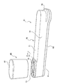
- FIG. 2 to 4A show details of the dresser arm 51.
- FIG. FIG. 2 shows a state where the cover 70 is attached to the dresser arm main body 60.
- FIG. 3 shows a state where the cover 70 is removed from the dresser arm main body 60.
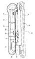
- FIG. 4A shows a cross section of the dresser arm 51 along the line AA shown in FIG.
- the cover 70 is disposed on the dresser arm main body 60 and covers the upper portion of the dresser arm main body 60.
- the cover 70 includes a top surface 71 and a side surface 72, and an opening 73 is formed on the distal end side (dressing member 52 side) of the dresser arm 51.
- the opening 73 is used for attaching a motor for operating the dressing member 52.
- a horizontal surface 74 is formed on the inner peripheral side of the opening 73.
- One bolt hole 75 is formed in the horizontal plane 74.
- the top surface 71 has a central portion 71a in the cross section formed horizontally, and is inclined so that the height decreases from the central portion 71a to the outside.
- the central portion 71a is formed horizontally in order to form the reinforcing rib 71b (see FIG. 3) on the back side thereof, but may be formed as an inclined surface.
- the top surface 71 and the side surface 72 do not have any recesses, and do not have a horizontal surface (a surface perpendicular to the vertical direction) except for the central portion 71a.
- the arc-shaped surface 76 formed on the base end side (the side opposite to the dressing member 52) of the cover 70 is also inclined so that the height decreases from the inside toward the outside.
- a horizontal plane is formed around the opening 73, and this portion is a region that is not exposed to the outside when the auxiliary cover 80 is attached. That is, no recess is formed on the outer surface of the cover 70 exposed to the outside, and no horizontal plane is formed except for the central portion 71a.
- the slurry does not scatter and stay in the recess. Further, since the outer surface of the cover 70 exposed to the outside does not have a horizontal surface except for the central portion 71a, the scattered slurry is likely to fall, and thus the slurry adheres to the outer surface over a long period of time. Is suppressed. Therefore, it is possible to prevent the slurry scattered on the outer surface of the cover 70 from adhering to the cover 70 and dropping the adhering substance during the polishing of the wafer W to cause trouble. Furthermore, in this embodiment, the outer surface of the cover 70 exposed to the outside has water repellency. For this reason, since the scattered slurry falls quickly, the sticking suppression effect of the slurry is promoted.
- Water repellency can be imparted, for example, by coating with a water repellent paint.
- the central portion 71a of the top surface 71 is formed as a horizontal plane.
- the polishing liquid supply nozzle 40 is supplied. From the mouth and the polishing pad 25, the slurry scatters upward against the gravity, reaches the central portion 71a, and is less likely to stick to it.
- the upper surface 81 formed as a horizontal plane of the auxiliary cover 80 The same applies to the upper surface 81 formed as a horizontal plane of the auxiliary cover 80.
- a stepped portion 61 is formed on the outer edge portion of the dresser arm main body 60.
- a horizontal surface 62 is formed.
- a support portion 63 extending in the vertical direction is formed on the distal end side of the dresser arm main body 60.
- the support part 63 supports the cover 70 when the cover 70 is attached to the dresser arm main body 60.
- Bolt holes 64 are formed on the top surface of the support portion 63.
- a pair of ball catch mechanisms 91 are provided on the inner side of the cover 70 (more specifically, the reinforcing rib 71 b) and the top surface of the dresser arm main body 60. In this embodiment, two sets of the pair of ball catch mechanisms 91 are provided, but the number thereof can be set arbitrarily.
- the user can lock the cover 70 to the dresser arm body 60 with one touch.
- the user may fasten the dresser arm main body 60 and the cover 70 with the ball catch mechanism 91 and then tighten the bolt using the bolt hole 75 and the bolt hole 64.
- the dresser arm main body 60 and the cover 70 can be more firmly fixed. Since the dresser arm main body 60 and the cover 70 are locked by the ball catch mechanism 91, a sufficient fixing relationship can be obtained only by bolting at one place.
- various locking mechanisms such as a magnet (may be a magnet catch mechanism) may be used. According to such a configuration, it is possible to greatly reduce the man-hours and time for attaching the cover 70.
- a protrusion 77 is formed on the inner side of the side surface 72 of the cover 70, that is, on the inner surface, near the lower end of the cover 70.
- the protrusion 77 protrudes toward the inside of the cover 70.
- the protrusion part 77 is formed over the whole cover 70 along the horizontal direction.
- a foamable sealing member 92 is disposed between the protruding portion 77 and the dresser arm main body 60.
- the foamable sealing member 92 is a nor seal. Since the foamable sealing member 92 is excellent in shape followability, as described above, even when the dresser arm body 60 and the cover 70 are fixed by bolting at the ball catch mechanism 91 and one place, Sufficient sealing performance is obtained.
- FIG. 4B is an enlarged view of region B shown in FIG. 4A.
- the thickness W2 of the cover 70 (side surface 72) at the contact portion between the outer edge portion of the dresser arm body 60 (that is, the horizontal surface 62) and the outer edge portion of the cover 70 (that is, the end surface 78 of the side surface 72). Is thinner than the thickness W1 of the cover 70 other than the contact portion.
- the horizontal surface 62 of the dresser arm body 60 is formed so as not to protrude outward from the end surface 78. According to this configuration, the distance in the thickness direction of the contact portion can be reduced.
- FIG. 5 shows a dresser arm 151 as a comparative example.
- the cover 170 includes a top surface 171 formed as a horizontal surface and a side surface 172.
- a flange portion 173 serving as a horizontal surface is formed on the outer edge of the side surface 172.
- the cover 170 is fixed to the dresser arm main body 60 by a large number of bolts 181 at the flange portion 173. According to such a configuration, a large number of horizontal surfaces are formed, so that there is a high risk that the slurry will stick.
- the flange portion 173 and the head portion of the bolt 181 are in a relatively low position and close to the slurry supply port and the polishing pad 25 in the vertical direction. Is easy to stick. Further, the man-hours and time required for attaching the cover 170 are extremely increased.
- the cover 70 of the present embodiment described above does not require bolting at many places, the heads of the flange portion 173 and the bolt 181 are not formed.
- the cover 70 can simultaneously realize the suppression of slurry adhesion and the reduction in the number of mounting steps and the mounting time by correlating the mounting structure and the shape of the cover 70 with each other.
- the cover is a locking mechanism for locking the main body of the component and the cover, and includes a locking mechanism provided inside the cover. It can also be carried out separately from the shape. According to such a configuration, as described above, the effect of reducing the number of mounting steps and the mounting time of the cover is suitably achieved.
Landscapes
- Engineering & Computer Science (AREA)
- Mechanical Engineering (AREA)
- Finish Polishing, Edge Sharpening, And Grinding By Specific Grinding Devices (AREA)
- Mechanical Treatment Of Semiconductor (AREA)
- Grinding-Machine Dressing And Accessory Apparatuses (AREA)
- Auxiliary Devices For Machine Tools (AREA)
Abstract
Description
20…研磨テーブル
25…研磨パッド
30…トップリング
35…支持アーム
40…研磨液供給ノズル
50…ドレッサ
51…ドレッサアーム
52…ドレッシング部材
60…ドレッサアーム本体
61…段部
62…水平面
63…支持部
64…ボルト穴
70…カバー
71…頂面
71a…中央部
71b…補強リブ
72…側面
73…開口部
74…水平面
75…ボルト穴
76…面
77…突出部
78…端面
80…補助カバー
81…上面
91…ボールキャッチ機構
92…発泡性シール部材
W…ウェハ
Claims (8)
- 基板を研磨するための研磨装置の構成部品用のカバーであって、
前記構成部品の本体と前記カバーとを係止するための係止機構であって、前記カバーの内部に設けられた係止機構を備え、
外部に露出される前記カバーの外表面は、凹部を有しておらず、前記カバーの頂部を除いて、水平面を有していない
カバー。 - 請求項1に記載のカバーであって、
前記係止機構は、ボールキャッチ機構またはマグネットを備える
カバー。 - 請求項1または請求項2に記載のカバーであって、
前記外部に露出されるカバーの外表面は、撥水性を有する
カバー。 - 請求項1ないし請求項3のいずれか一項に記載のカバーであって、
前記構成部品の本体の外縁部と前記カバーの外縁部との当接部分における前記カバーの厚みは、前記当接部分以外における前記カバーの厚みよりも薄い
カバー。 - 研磨装置の構成部品であって、
前記構成部品の本体と、
請求項1ないし請求項4のいずれか一項に記載のカバーと
を備える構成部品。 - 請求項5に記載の構成部品であって、
前記カバーの内面には、該カバーの内側に向けて突出する突出部が水平方向に沿って前記カバーの全体にわたって形成されており、
前記構成部品は、前記構成部品の本体と、前記突出部との間に配置される発泡性シール部材を備える
構成部品。 - 請求項5または請求項6に記載の構成部品であって、
前記カバーの上に配置される補助カバーであって、前記カバーの一部の領域を覆うための補助カバーを備え、
前記カバーは、前記補助カバーによって覆われる領域内に、前記カバーと前記構成部品本体とを固定するために使用されるボルト穴が形成された水平面を有する
構成部品。 - 研磨装置であって、
請求項5ないし請求項7のいずれか一項に記載の構成部品を備える
研磨装置。
Priority Applications (4)
| Application Number | Priority Date | Filing Date | Title |
|---|---|---|---|
| SG11201509461XA SG11201509461XA (en) | 2014-03-31 | 2015-03-27 | Cover For Component Of Polishing Apparatus, Component Of Polishing Apparatus, And Polishing Apparatus |
| CN201580000586.4A CN106132633B (zh) | 2014-03-31 | 2015-03-27 | 研磨装置的构成部件用的罩、研磨装置的构成部件以及研磨装置 |
| US14/787,424 US9724798B2 (en) | 2014-03-31 | 2015-03-27 | Cover for component of polishing apparatus, component of polishing apparatus, and polishing apparatus |
| KR1020157030934A KR102361932B1 (ko) | 2014-03-31 | 2015-03-27 | 연마 장치의 구성 부품용 커버, 연마 장치의 구성 부품 및 연마 장치 |
Applications Claiming Priority (2)
| Application Number | Priority Date | Filing Date | Title |
|---|---|---|---|
| JP2014-072227 | 2014-03-31 | ||
| JP2014072227A JP6342198B2 (ja) | 2014-03-31 | 2014-03-31 | 研磨装置の構成部品用のカバー、研磨装置の構成部品、および、研磨装置 |
Publications (1)
| Publication Number | Publication Date |
|---|---|
| WO2015152052A1 true WO2015152052A1 (ja) | 2015-10-08 |
Family
ID=54240378
Family Applications (1)
| Application Number | Title | Priority Date | Filing Date |
|---|---|---|---|
| PCT/JP2015/059631 Ceased WO2015152052A1 (ja) | 2014-03-31 | 2015-03-27 | 研磨装置の構成部品用のカバー、研磨装置の構成部品、および、研磨装置 |
Country Status (7)
| Country | Link |
|---|---|
| US (1) | US9724798B2 (ja) |
| JP (2) | JP6342198B2 (ja) |
| KR (1) | KR102361932B1 (ja) |
| CN (1) | CN106132633B (ja) |
| SG (1) | SG11201509461XA (ja) |
| TW (2) | TWI725471B (ja) |
| WO (1) | WO2015152052A1 (ja) |
Families Citing this family (3)
| Publication number | Priority date | Publication date | Assignee | Title |
|---|---|---|---|---|
| JP7774571B2 (ja) * | 2021-06-11 | 2025-11-21 | 株式会社荏原製作所 | 研磨装置 |
| CN113696094B (zh) * | 2021-09-03 | 2022-07-12 | 山西光兴光电科技有限公司 | 研磨水罩机构、研磨机及研磨机控制方法 |
| JP7850056B2 (ja) * | 2022-10-28 | 2026-04-22 | 株式会社荏原製作所 | 基板処理装置 |
Citations (4)
| Publication number | Priority date | Publication date | Assignee | Title |
|---|---|---|---|---|
| JP2002058543A (ja) * | 2000-08-21 | 2002-02-26 | Nissin Electric Co Ltd | 監視制御卓及び該制御卓に用いる配線用キャップ |
| JP2004356517A (ja) * | 2003-05-30 | 2004-12-16 | Ebara Corp | 基板洗浄装置及び基板洗浄方法 |
| JP2007168039A (ja) * | 2005-12-22 | 2007-07-05 | Ebara Corp | 研磨テーブルの研磨面洗浄機構、及び研磨装置 |
| JP2013141735A (ja) * | 2012-01-12 | 2013-07-22 | Ebara Corp | 研磨装置 |
Family Cites Families (19)
| Publication number | Priority date | Publication date | Assignee | Title |
|---|---|---|---|---|
| US2973605A (en) * | 1959-11-09 | 1961-03-07 | Carman Lab Inc | Lapping machine |
| JPS62165838U (ja) * | 1986-04-10 | 1987-10-21 | ||
| US5785585A (en) * | 1995-09-18 | 1998-07-28 | International Business Machines Corporation | Polish pad conditioner with radial compensation |
| US6036583A (en) * | 1997-07-11 | 2000-03-14 | Applied Materials, Inc. | Conditioner head in a substrate polisher and method |
| JP3965503B2 (ja) * | 1998-03-25 | 2007-08-29 | 未来工業株式会社 | 切粉受けカバー体を備えた穿孔具 |
| US6200199B1 (en) * | 1998-03-31 | 2001-03-13 | Applied Materials, Inc. | Chemical mechanical polishing conditioner |
| US6135855A (en) * | 1998-07-30 | 2000-10-24 | Motorola, Inc. | Translation mechanism for a chemical mechanical planarization system and method therefor |
| JP2001300847A (ja) | 2000-04-24 | 2001-10-30 | Nikon Corp | 研磨装置及び半導体デバイス製造方法 |
| US6315651B1 (en) * | 2001-03-22 | 2001-11-13 | Taiwan Semiconductor Manufacturing Company Ltd | Easy on/off cover for a pad conditioning assembly |
| KR100462868B1 (ko) * | 2001-06-29 | 2004-12-17 | 삼성전자주식회사 | 반도체 폴리싱 장치의 패드 컨디셔너 |
| JP2003136364A (ja) * | 2001-11-06 | 2003-05-14 | Enshu Ltd | 工作機械の密閉装置 |
| JP2003179021A (ja) * | 2001-12-11 | 2003-06-27 | Sony Corp | 化学機械研磨装置 |
| KR20060124501A (ko) * | 2005-05-31 | 2006-12-05 | 삼성전자주식회사 | Cmp 설비의 패드 컨디셔너 |
| JP4791813B2 (ja) * | 2005-12-08 | 2011-10-12 | 株式会社ディスコ | 切削装置 |
| JP5096100B2 (ja) * | 2007-10-05 | 2012-12-12 | 株式会社ディスコ | 切削装置 |
| DE102010012378B3 (de) * | 2010-03-22 | 2011-09-22 | Solarlux Aluminium Systeme Gmbh | Schiebewand |
| CN202240906U (zh) * | 2011-09-28 | 2012-05-30 | 东北林业大学 | 电火花成形砂轮在线修整装置 |
| TWM438343U (en) * | 2012-05-04 | 2012-10-01 | Warde Tec Taiwan Co Ltd | Conditioner cover |
| CN103639897A (zh) * | 2013-11-01 | 2014-03-19 | 无锡元明机械设备技术有限公司 | 一种研磨机研磨盘修整装置 |
-
2014
- 2014-03-31 JP JP2014072227A patent/JP6342198B2/ja active Active
-
2015
- 2015-03-27 US US14/787,424 patent/US9724798B2/en active Active
- 2015-03-27 WO PCT/JP2015/059631 patent/WO2015152052A1/ja not_active Ceased
- 2015-03-27 KR KR1020157030934A patent/KR102361932B1/ko active Active
- 2015-03-27 CN CN201580000586.4A patent/CN106132633B/zh active Active
- 2015-03-27 SG SG11201509461XA patent/SG11201509461XA/en unknown
- 2015-03-30 TW TW108123877A patent/TWI725471B/zh active
- 2015-03-30 TW TW104110199A patent/TWI672194B/zh active
-
2018
- 2018-02-26 JP JP2018031845A patent/JP6580178B2/ja active Active
Patent Citations (4)
| Publication number | Priority date | Publication date | Assignee | Title |
|---|---|---|---|---|
| JP2002058543A (ja) * | 2000-08-21 | 2002-02-26 | Nissin Electric Co Ltd | 監視制御卓及び該制御卓に用いる配線用キャップ |
| JP2004356517A (ja) * | 2003-05-30 | 2004-12-16 | Ebara Corp | 基板洗浄装置及び基板洗浄方法 |
| JP2007168039A (ja) * | 2005-12-22 | 2007-07-05 | Ebara Corp | 研磨テーブルの研磨面洗浄機構、及び研磨装置 |
| JP2013141735A (ja) * | 2012-01-12 | 2013-07-22 | Ebara Corp | 研磨装置 |
Also Published As
| Publication number | Publication date |
|---|---|
| JP6580178B2 (ja) | 2019-09-25 |
| KR102361932B1 (ko) | 2022-02-11 |
| JP2018114614A (ja) | 2018-07-26 |
| CN106132633B (zh) | 2018-11-27 |
| US20170008144A1 (en) | 2017-01-12 |
| US9724798B2 (en) | 2017-08-08 |
| CN106132633A (zh) | 2016-11-16 |
| TW201544251A (zh) | 2015-12-01 |
| TW201945125A (zh) | 2019-12-01 |
| TWI672194B (zh) | 2019-09-21 |
| JP2015193055A (ja) | 2015-11-05 |
| TWI725471B (zh) | 2021-04-21 |
| JP6342198B2 (ja) | 2018-06-13 |
| KR20160140338A (ko) | 2016-12-07 |
| SG11201509461XA (en) | 2016-01-28 |
Similar Documents
| Publication | Publication Date | Title |
|---|---|---|
| CN103962938B (zh) | 研磨装置 | |
| JP6580178B2 (ja) | 研磨装置の構成部品用のカバー、研磨装置の構成部品、および、研磨装置 | |
| TWI577497B (zh) | Grinding device | |
| US8579679B2 (en) | Conditioning method and conditioning apparatus for polishing pad for use in double side polishing device | |
| JP6717691B2 (ja) | 基板処理装置 | |
| TWI746645B (zh) | 半導體裝置的製造方法和半導體製造裝置 | |
| JP2017501899A (ja) | ウェハ研削装置 | |
| CN106312780A (zh) | 抛光设备 | |
| US20160144478A1 (en) | Apparatus for cleaning a polishing surface, polishing apparatus, and method of manufacturing an apparatus for cleaning a polishing surface | |
| JP6259366B2 (ja) | 研磨装置 | |
| JP2019209410A (ja) | 研磨装置、及び研磨装置のための洗浄方法 | |
| JP2017013183A (ja) | 研磨装置 | |
| US20200198090A1 (en) | Cmp apparatus and method of performing ceria-based cmp process | |
| CN216000031U (zh) | 研磨装置及化学机械研磨机台 | |
| JP6578040B2 (ja) | 基板処理装置 | |
| JP7764264B2 (ja) | 被加工物の加工方法 | |
| JP2016119368A (ja) | コンディショニング装置、バフ処理装置、基板処理装置、ドレッサ、および、コンディショニング方法 | |
| CN223057444U (zh) | 研磨头清洗组件以及抛光机台 | |
| KR20100044988A (ko) | 화학적 기계적 연마 장비의 폴리싱 패드 이물질 제거장치 | |
| US20210154795A1 (en) | Polishing head for use in chemical mechanical polishing and cmp apparatus having the same | |
| TW202247941A (zh) | 研磨装置 | |
| JP2017196725A (ja) | ラッピング研磨用定盤およびそれを用いる装置 | |
| JP2015223641A (ja) | 研磨装置 | |
| KR20070027294A (ko) | 화학적 기계적 연마 장비 |
Legal Events
| Date | Code | Title | Description |
|---|---|---|---|
| ENP | Entry into the national phase |
Ref document number: 20157030934 Country of ref document: KR Kind code of ref document: A |
|
| WWE | Wipo information: entry into national phase |
Ref document number: 14787424 Country of ref document: US |
|
| 121 | Ep: the epo has been informed by wipo that ep was designated in this application |
Ref document number: 15774192 Country of ref document: EP Kind code of ref document: A1 |
|
| NENP | Non-entry into the national phase | ||
| 122 | Ep: pct application non-entry in european phase |
Ref document number: 15774192 Country of ref document: EP Kind code of ref document: A1 |