WO2015151724A1 - トレーリングアーム取付部構造 - Google Patents
トレーリングアーム取付部構造 Download PDFInfo
- Publication number
- WO2015151724A1 WO2015151724A1 PCT/JP2015/056723 JP2015056723W WO2015151724A1 WO 2015151724 A1 WO2015151724 A1 WO 2015151724A1 JP 2015056723 W JP2015056723 W JP 2015056723W WO 2015151724 A1 WO2015151724 A1 WO 2015151724A1
- Authority
- WO
- WIPO (PCT)
- Prior art keywords
- vehicle
- trailing arm
- width direction
- side member
- side sill
- Prior art date
- Legal status (The legal status is an assumption and is not a legal conclusion. Google has not performed a legal analysis and makes no representation as to the accuracy of the status listed.)
- Ceased
Links
Images


Classifications
-
- B—PERFORMING OPERATIONS; TRANSPORTING
- B62—LAND VEHICLES FOR TRAVELLING OTHERWISE THAN ON RAILS
- B62D—MOTOR VEHICLES; TRAILERS
- B62D21/00—Understructures, i.e. chassis frame on which a vehicle body may be mounted
- B62D21/11—Understructures, i.e. chassis frame on which a vehicle body may be mounted with resilient means for suspension, e.g. of wheels or engine; sub-frames for mounting engine or suspensions
-
- B—PERFORMING OPERATIONS; TRANSPORTING
- B62—LAND VEHICLES FOR TRAVELLING OTHERWISE THAN ON RAILS
- B62D—MOTOR VEHICLES; TRAILERS
- B62D25/00—Superstructure or monocoque structure sub-units; Parts or details thereof not otherwise provided for
- B62D25/20—Floors or bottom sub-units
- B62D25/2009—Floors or bottom sub-units in connection with other superstructure subunits
- B62D25/2027—Floors or bottom sub-units in connection with other superstructure subunits the subunits being rear structures
Definitions
- the present invention relates to a trailing arm attachment structure for attaching a trailing arm of a torsion beam type rear suspension at the rear of a vehicle to a vehicle in a swingable manner.
- the torsion beam type rear suspension is a kind of vehicle suspension type.
- trailing arms are disposed on the left and right sides of a torsion beam (also referred to as a cross beam) that extends in the vehicle width direction below the floor surface at the rear of the vehicle.
- a torsion beam also referred to as a cross beam
- the torsion beam type rear suspension is swingably supported by the rear part of the vehicle (for example, Patent Document 1).
- the bending arm and the torsional load from the torsion beam are applied to the trailing arm mounting location more than other locations. For this reason, high rigidity is required at the mounting position of the trailing arm to ensure steering stability and NVH (Noise, Vibration, Harshness).
- the trailing arm has a built-in bush for mitigating the vibration during driving on the road surface because the vibration is input from the rear tire. In order to make this bush function effectively, high rigidity is required locally at the mounting position of the trailing arm.
- the rigidity of the mounting position can be improved.
- the reinforcing member of Patent Document 1 is simply a member obtained by bending a plate-like member, it is unlikely that high rigidity can be obtained at the reinforcing member itself, and by extension, at the mounting position of the trailing arm.
- the reinforcing member is joined to the longitudinal surfaces of the inner support wall and the rear frame as in Patent Document 1, there is a possibility that the rigidity against the load in the vehicle width direction is insufficient.
- the present invention has been made in view of such problems, and an object thereof is to provide a trailing arm mounting portion structure capable of obtaining high rigidity at a trailing arm mounting position while suppressing an increase in the weight and cost of a vehicle. It is said.
- a typical structure of the trailing arm mounting portion structure is a trailing arm mounting portion structure in which the trailing arm of a torsion beam type rear suspension at the rear of the vehicle is swingably mounted on the vehicle.
- a side member extending in the vehicle front-rear direction below the rear floor panel constituting the floor surface of the rear portion of the vehicle, a side sill extending in the vehicle front-rear direction on the vehicle outer side of the side member,
- a bracket that extends downward along the vertical surface is attached to the side member in the vicinity of the rear end of the side sill, and supports the trailing arm through a bolt that serves as a swing shaft of the side sill.
- the reinforcing member further includes a reinforcing member that connects the lower surface of the side member and the lower surface of the side sill, and the reinforcing member includes a lower surface of the side member, a vertical surface on the inner side in the vehicle width direction of the side sill, It has the plane part which has the area
- the reinforcing member is attached to the side member and the side sill, which are structural members of the vehicle body, in addition to the bracket, the load applied to the bracket can be suitably distributed throughout the vehicle body. Thereby, a reinforcement effect is heightened and a deformation
- the reinforcing member is attached to the bracket in the vehicle height direction, and is attached to the side member and the side sill in the vehicle width direction. Thereby, the rigidity with respect to the load of a vehicle width direction is improved.
- the reinforcing member has a flat surface portion in addition to the surface extending from the lower surface of the side member along the vertical surface on the inner side in the vehicle width direction of the bracket.
- the support point of the bolt in the reinforcing member is preferably located in the region when viewed from the front of the vehicle. According to such a configuration, the support point of the bolt is located in a region reinforced by the flat portion when viewed from the front of the vehicle. Thereby, the rigidity in the vicinity of the support point of the bolt where the load from the trailing arm concentrates most in the bracket can be increased, and deformation due to the load can be suppressed.
- the support point of the bolt in the reinforcing member may be located on a line segment connecting the end of the lower surface of the side member on the inner side in the vehicle width direction and the lower end of the vertical surface on the inner side of the side sill in the vehicle width direction.
- FIG. 1 is an overall perspective view of a vehicle including a trailing arm mounting portion structure according to the present embodiment. It is the whole perspective view which observed the vehicle shown in FIG. 1 from the downward direction.
- FIG. 3 is an enlarged view within a broken-line circle in FIG. 2. It is a figure which shows the state which observed the reinforcement member shown in FIG. 3 from A direction.
- FIG. 4 is a sectional view taken along line BB in FIG. 3. It is a figure which shows the state which observed the reinforcement member shown in FIG. 3 from the G direction. It is a figure which shows the state which observed the reinforcement member shown in FIG. 3 from the H direction.
- SYMBOLS 100 ... Mounting part structure, 100a ... Vehicle, 102 ... Rear floor panel, 104 ... Torsion beam, 106a ... Trailing arm, 106b ... Trailing arm, 110 ... Side member, 110a ... Lower surface, 120 ... Side sill, 120a ... Lower surface, 120b ... Longitudinal surface, 130 ... bracket, 140 ... reinforcing member, 142 ... flat surface portion, 144 ... bottom surface portion, 146 ... wall surface portion, 148 ... bulge portion, 160 ... bolt
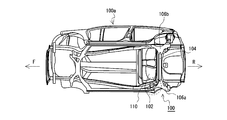
- FIG. 1 is an overall perspective view of a vehicle 100a provided with a trailing arm mounting portion structure (hereinafter simply referred to as a mounting portion structure 100) according to the present embodiment, and illustrates a state in which the vehicle 100a is observed from the left side. Yes.
- FIG. 2 is an overall perspective view of the vehicle 100a shown in FIG. 1 observed from below.
- the vehicle 100a is provided with a rear floor panel 102 that constitutes the floor surface of the rear portion of the vehicle.
- a rear floor side member (hereinafter referred to as a side member 110), which is a side member extending in the vehicle front-rear direction, is disposed below the rear floor panel 102.
- the rear wheel (not shown) of the vehicle 100a is supported by the torsion beam type rear suspension.
- trailing arms 106a and 106b for supporting the rear wheels are arranged at both ends of the torsion beam 104 extending in the vehicle width direction.
- Such trailing arms 106a and 106b are swingably attached to the vehicle.
- the attachment part structure 100 of this embodiment is a structure for attaching these trailing arms 106a and 106b to the vehicle 100a.
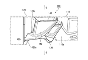
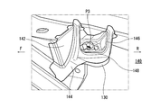
- FIG. 3 is an enlarged view in the broken-line circle in FIG. 2, and illustrates a state in which the broken-line circle in FIG. 2 is observed from the lower side of the vehicle.
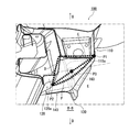
- FIG. 4 is a view showing a state in which the reinforcing member 140 shown in FIG. 3 is observed from the A direction.
- FIG. 5 is a cross-sectional view taken along the line BB of FIG. 3 and illustrates a state in which the reinforcing member 140 is partially transmitted for easy understanding.
- a side sill 120 extending in the vehicle front-rear direction is disposed on the vehicle outer side of the side member 110.
- the lower surface 110 a of the side member 110 is positioned above the lower surface 120 a of the side sill 120.
- a suspension mounting bush (not shown) is disposed between the side member 110 and the side sill 120 and is attached by being sandwiched between the side sill 120 and a bracket 130 described later. The bush is fixed to the car body.
- a bolt 160 that is a swinging shaft of the trailing arm 106 a (see FIG. 1) is penetrated and supported inside the side sill 120 and below the side member 110.
- a bracket 130 is disposed. As shown in FIGS. 4 and 5, the bracket 130 extends downward from the lower surface 110 a of the side member 110 along the longitudinal surface 120 b on the inner side in the vehicle width direction of the side sill 120, and is attached to the side member 110 near the rear end of the side sill 120. It is attached.
- the attachment portion structure 100 of the present embodiment further includes a reinforcing member 140 that reinforces the bracket 130 (see FIGS. 4 and 5).
- the reinforcing member 140 is attached to the vehicle inner surface of the bracket 130 and connects the lower surface 110 a of the side member 110 and the lower surface 120 a of the side sill 120 across them. That is, in the mounting portion structure 100 of the present embodiment, the bracket 130, the side member 110, and the side sill 120 are connected by the reinforcing member 140.
- the load applied to the bracket 130 from the trailing arms 106a and 106b via the bolt 160 (see FIG. 5) is reduced. It is preferably dispersed in the side member 110 and the side sill 120 which are structural members. Thereby, the reinforcement effect by the bracket 130 is enhanced, and the deformation of the bracket 130 due to the load is prevented. That is, it is possible to improve the rigidity of the trailing arm mounting portion.
- the reinforcing member 140 is attached to the vehicle inner surface of the bracket 130 in the vehicle height direction, and the lower surface 110 a of the side member 110 and the lower surface of the side sill 120 in the vehicle width direction. It is attached to 120a. As a result, the rigidity against the load in the vehicle width direction can be increased.
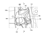
- the reinforcing member 140 has a flat portion 142 as shown in FIG.
- the plane portion 142 includes a lower surface 110 a (line segment C) of the side member 110 and a vertical surface (line segment D) inside the side sill 120 in the vehicle width direction. And a region surrounded by an arc E connecting the end P1 on the inner side in the vehicle width direction of the lower surface 110a of the side member 110 to the lower end P2 of the vertical surface on the inner side in the vehicle width direction of the side sill 120.
- the reinforcing member 140 has a three-dimensional shape including the vertical surface portion 144 (see FIG.
- the configuration in which P1 and P2 are connected by the arc E is illustrated.
- P1 and P2 may be connected by a line segment F that is a straight line.
- the region surrounded by the line segment C, the line segment D, and the arc E is substantially fan-shaped, whereas the region surrounded by the line segment C, the line segment D, and the line segment F is substantially triangular. It becomes a shape.
- the end portion of the arc E of the reinforcing member includes the end portion P1 (ridgeline) on the inner side in the vehicle width direction of the lower surface 110a of the side member 110 and the lower end P2 of the vertical surface on the inner side in the vehicle width direction of the side sill 120.
- these ends P1 and P2 are bent portions between two surfaces of each member, they have high rigidity. Therefore, by disposing the arc ends of the reinforcing member 140 on the ends P1 and P2 as in this embodiment, the deformation of the reinforcing member 140 can be more suitably suppressed.
- the load from the trailing arms 106a and 106b is preferably dispersed by connecting the bracket 130, the side member 110, and the side sill 120 with the reinforcing member 140. Can do. Further, by providing the reinforcing member 140 with the flat surface portion 142, deformation of the reinforcing member 140 is suppressed, and the reinforcing effect can be enhanced. Therefore, by changing the joint location and shape of the reinforcing member 140, high rigidity can be obtained at the attachment locations of the trailing arms 106a and 106b while suppressing an increase in the weight and cost of the vehicle.
- the support point P3 of the bolt 160 in the reinforcing member 140 is located in the region where the flat surface portion 142 is provided in the vehicle front view (in the region surrounded by the broken line). Is located.
- the support point P3 of the bolt 160 is located in a region reinforced by the flat portion 142 in the vehicle front view. Accordingly, the rigidity of the bolt 160 in the vicinity of the support point P3 can be increased, and deformation of the bracket 130 where the loads from the trailing arm trailing arms 106a and 106b are concentrated can be suitably prevented.
- the support point P3 of the bolt 160 in the reinforcing member 140 is positioned between the end portion P1 on the vehicle width direction inner side end P1 of the lower surface 110a of the side member 110 and the side sill 120. It is located on a line segment F connecting the lower end P2 of the vertical surface on the inner side in the width direction.
- FIG. 6 is a diagram showing a state where the reinforcing member 140 shown in FIG. 3 is observed from the G direction
- FIG. 7 is a diagram showing a state where the reinforcing member 140 shown in FIG. 3 is observed from the H direction.
- the side member arc E the vehicle width of the side sill 120 from the inner side end portion P ⁇ b> 1 of the lower surface of the side member in the vehicle width direction
- a flange-shaped lower surface portion 144 extending in the vehicle front-rear direction from an arc connecting to the lower end P2 of the vertical surface on the inner side in the direction (see FIG. 5) is provided.
- the flat portion 142 bulges in the vehicle width direction below the support point P ⁇ b> 3 of the bolt 160 (see FIG. 5).
- the bulging part 148 which connects the wall surface part 146 provided in the vehicle rear side rather than the part 142 is provided.
- the bulging portion 148 by connecting the flat portion 142 and the wall surface portion 146 provided in pairs in the vehicle longitudinal direction by the bulging portion 148, the vehicle longitudinal direction applied to the reinforcing member 140 from the trailing arms 106a and 106b.
- the rigidity against the load can be increased. Therefore, the deformation of the reinforcing member 140 and the vehicle body can be more effectively suppressed.
- the present invention can be used for a trailing arm mounting portion structure in which a trailing arm of a torsion beam type rear suspension at the rear of the vehicle is swingably mounted on the vehicle.
Landscapes
- Engineering & Computer Science (AREA)
- Chemical & Material Sciences (AREA)
- Combustion & Propulsion (AREA)
- Transportation (AREA)
- Mechanical Engineering (AREA)
- Body Structure For Vehicles (AREA)
- Vehicle Body Suspensions (AREA)
Priority Applications (2)
| Application Number | Priority Date | Filing Date | Title |
|---|---|---|---|
| DE112015000046.1T DE112015000046B4 (de) | 2014-03-31 | 2015-03-06 | Längslenker-anbringungsstruktur |
| CN201580000650.9A CN105164003B (zh) | 2014-03-31 | 2015-03-06 | 拖臂安装部结构 |
Applications Claiming Priority (2)
| Application Number | Priority Date | Filing Date | Title |
|---|---|---|---|
| JP2014072678A JP6331589B2 (ja) | 2014-03-31 | 2014-03-31 | トレーリングアーム取付部構造 |
| JP2014-072678 | 2014-03-31 |
Publications (1)
| Publication Number | Publication Date |
|---|---|
| WO2015151724A1 true WO2015151724A1 (ja) | 2015-10-08 |
Family
ID=54240057
Family Applications (1)
| Application Number | Title | Priority Date | Filing Date |
|---|---|---|---|
| PCT/JP2015/056723 Ceased WO2015151724A1 (ja) | 2014-03-31 | 2015-03-06 | トレーリングアーム取付部構造 |
Country Status (4)
| Country | Link |
|---|---|
| JP (1) | JP6331589B2 (enExample) |
| CN (1) | CN105164003B (enExample) |
| DE (1) | DE112015000046B4 (enExample) |
| WO (1) | WO2015151724A1 (enExample) |
Cited By (1)
| Publication number | Priority date | Publication date | Assignee | Title |
|---|---|---|---|---|
| CN115158462A (zh) * | 2022-06-28 | 2022-10-11 | 一汽奔腾轿车有限公司 | 一种汽车后纵梁总成 |
Families Citing this family (2)
| Publication number | Priority date | Publication date | Assignee | Title |
|---|---|---|---|---|
| CN106314538A (zh) * | 2016-09-20 | 2017-01-11 | 奇瑞汽车股份有限公司 | 一种汽车侧面碰撞拖曳臂安装加强结构 |
| EP3587222B1 (en) * | 2018-06-26 | 2021-12-22 | Mazda Motor Corporation | Lower vehicle-body structure of vehicle |
Citations (4)
| Publication number | Priority date | Publication date | Assignee | Title |
|---|---|---|---|---|
| JPS6284586U (enExample) * | 1985-11-19 | 1987-05-29 | ||
| JPH0313205U (enExample) * | 1989-06-26 | 1991-02-12 | ||
| JP2007131271A (ja) * | 2005-11-14 | 2007-05-31 | Suzuki Motor Corp | 車両のリアサスペンション取付け構造 |
| JP2012051497A (ja) * | 2010-09-02 | 2012-03-15 | Suzuki Motor Corp | トレーリングアームの取付構造 |
Family Cites Families (7)
| Publication number | Priority date | Publication date | Assignee | Title |
|---|---|---|---|---|
| JP2586673Y2 (ja) | 1991-08-22 | 1998-12-09 | 三ツ星ベルト株式会社 | 動力伝動ベルト |
| JP3404980B2 (ja) * | 1995-04-18 | 2003-05-12 | 日産自動車株式会社 | 自動車のリヤサイドメンバ構造 |
| JP2007283884A (ja) * | 2006-04-17 | 2007-11-01 | Mazda Motor Corp | 自動車の下部構造 |
| KR100844695B1 (ko) * | 2007-10-23 | 2008-07-07 | 현대자동차주식회사 | 차량의 트레일링암 마운팅부 구조 |
| JP4923026B2 (ja) | 2008-11-04 | 2012-04-25 | 本田技研工業株式会社 | サスペンションアームの支持構造 |
| CN103958332B (zh) * | 2011-11-25 | 2016-07-06 | 本田技研工业株式会社 | 车体侧部结构 |
| JP6372057B2 (ja) | 2013-07-08 | 2018-08-15 | スズキ株式会社 | トレーリングアーム取付部構造 |
-
2014
- 2014-03-31 JP JP2014072678A patent/JP6331589B2/ja active Active
-
2015
- 2015-03-06 CN CN201580000650.9A patent/CN105164003B/zh active Active
- 2015-03-06 WO PCT/JP2015/056723 patent/WO2015151724A1/ja not_active Ceased
- 2015-03-06 DE DE112015000046.1T patent/DE112015000046B4/de active Active
Patent Citations (4)
| Publication number | Priority date | Publication date | Assignee | Title |
|---|---|---|---|---|
| JPS6284586U (enExample) * | 1985-11-19 | 1987-05-29 | ||
| JPH0313205U (enExample) * | 1989-06-26 | 1991-02-12 | ||
| JP2007131271A (ja) * | 2005-11-14 | 2007-05-31 | Suzuki Motor Corp | 車両のリアサスペンション取付け構造 |
| JP2012051497A (ja) * | 2010-09-02 | 2012-03-15 | Suzuki Motor Corp | トレーリングアームの取付構造 |
Cited By (2)
| Publication number | Priority date | Publication date | Assignee | Title |
|---|---|---|---|---|
| CN115158462A (zh) * | 2022-06-28 | 2022-10-11 | 一汽奔腾轿车有限公司 | 一种汽车后纵梁总成 |
| CN115158462B (zh) * | 2022-06-28 | 2024-05-10 | 一汽奔腾轿车有限公司 | 一种汽车后纵梁总成 |
Also Published As
| Publication number | Publication date |
|---|---|
| DE112015000046T5 (de) | 2015-12-17 |
| JP2015193331A (ja) | 2015-11-05 |
| DE112015000046B4 (de) | 2020-08-06 |
| CN105164003A (zh) | 2015-12-16 |
| JP6331589B2 (ja) | 2018-05-30 |
| CN105164003B (zh) | 2017-03-15 |
Similar Documents
| Publication | Publication Date | Title |
|---|---|---|
| JP5299337B2 (ja) | 車両のサブフレーム構造 | |
| CN108349536B (zh) | 后副车架结构 | |
| JP6137488B2 (ja) | 自動車のリヤサブフレーム構造 | |
| JP6372057B2 (ja) | トレーリングアーム取付部構造 | |
| WO2017065086A1 (ja) | 車両の側部車体構造 | |
| JP6668743B2 (ja) | 車体構造 | |
| JP6052512B2 (ja) | 自動車のリヤサブフレーム構造 | |
| JP6074510B2 (ja) | 車両用リヤサスペンション取付構造の組付方法 | |
| CN108454700A (zh) | 车辆下部结构 | |
| JP6159974B2 (ja) | フロントクロスメンバ | |
| JP5968971B2 (ja) | 車体後部構造 | |
| JP4923026B2 (ja) | サスペンションアームの支持構造 | |
| JP6331589B2 (ja) | トレーリングアーム取付部構造 | |
| JP5426614B2 (ja) | トレーリングアームの取付構造 | |
| JP2008001307A (ja) | サスペンションフレーム構造 | |
| JP2002166714A (ja) | サスペンションアーム | |
| JP6156649B2 (ja) | 自動車のリヤサブフレーム構造 | |
| KR101982869B1 (ko) | 트레일링암의 마운팅브라켓 | |
| JP7161514B2 (ja) | 車体下部構造 | |
| JP6637361B2 (ja) | 車両用サスペンションブラケットの補強構造 | |
| JP6612094B2 (ja) | 車体後部構造 | |
| JP6066102B2 (ja) | 自動車のリヤサブフレーム構造 | |
| JP6137487B2 (ja) | 自動車のリヤサブフレーム構造 | |
| JP6164061B2 (ja) | トレーリングアーム取付部構造 | |
| JP6204159B2 (ja) | 車体後部構造 |
Legal Events
| Date | Code | Title | Description |
|---|---|---|---|
| WWE | Wipo information: entry into national phase |
Ref document number: 201580000650.9 Country of ref document: CN |
|
| WWE | Wipo information: entry into national phase |
Ref document number: 1120150000461 Country of ref document: DE Ref document number: 112015000046 Country of ref document: DE |
|
| WWE | Wipo information: entry into national phase |
Ref document number: IDP00201507043 Country of ref document: ID |
|
| 121 | Ep: the epo has been informed by wipo that ep was designated in this application |
Ref document number: 15773690 Country of ref document: EP Kind code of ref document: A1 |
|
| 122 | Ep: pct application non-entry in european phase |
Ref document number: 15773690 Country of ref document: EP Kind code of ref document: A1 |