WO2015147255A1 - 作業車両 - Google Patents
作業車両 Download PDFInfo
- Publication number
- WO2015147255A1 WO2015147255A1 PCT/JP2015/059594 JP2015059594W WO2015147255A1 WO 2015147255 A1 WO2015147255 A1 WO 2015147255A1 JP 2015059594 W JP2015059594 W JP 2015059594W WO 2015147255 A1 WO2015147255 A1 WO 2015147255A1
- Authority
- WO
- WIPO (PCT)
- Prior art keywords
- rotation speed
- fan
- speed
- engine
- overrun
- Prior art date
- Legal status (The legal status is an assumption and is not a legal conclusion. Google has not performed a legal analysis and makes no representation as to the accuracy of the status listed.)
- Ceased
Links
Images





Classifications
-
- E—FIXED CONSTRUCTIONS
- E02—HYDRAULIC ENGINEERING; FOUNDATIONS; SOIL SHIFTING
- E02F—DREDGING; SOIL-SHIFTING
- E02F9/00—Component parts of dredgers or soil-shifting machines, not restricted to one of the kinds covered by groups E02F3/00 - E02F7/00
- E02F9/20—Drives; Control devices
- E02F9/2058—Electric or electro-mechanical or mechanical control devices of vehicle sub-units
- E02F9/2095—Control of electric, electro-mechanical or mechanical equipment not otherwise provided for, e.g. ventilators, electro-driven fans
-
- B—PERFORMING OPERATIONS; TRANSPORTING
- B62—LAND VEHICLES FOR TRAVELLING OTHERWISE THAN ON RAILS
- B62D—MOTOR VEHICLES; TRAILERS
- B62D55/00—Endless track vehicles
- B62D55/06—Endless track vehicles with tracks without ground wheels
-
- E—FIXED CONSTRUCTIONS
- E02—HYDRAULIC ENGINEERING; FOUNDATIONS; SOIL SHIFTING
- E02F—DREDGING; SOIL-SHIFTING
- E02F9/00—Component parts of dredgers or soil-shifting machines, not restricted to one of the kinds covered by groups E02F3/00 - E02F7/00
- E02F9/02—Travelling-gear, e.g. associated with slewing gears
-
- E—FIXED CONSTRUCTIONS
- E02—HYDRAULIC ENGINEERING; FOUNDATIONS; SOIL SHIFTING
- E02F—DREDGING; SOIL-SHIFTING
- E02F9/00—Component parts of dredgers or soil-shifting machines, not restricted to one of the kinds covered by groups E02F3/00 - E02F7/00
- E02F9/08—Superstructures; Supports for superstructures
- E02F9/0858—Arrangement of component parts installed on superstructures not otherwise provided for, e.g. electric components, fenders, air-conditioning units
- E02F9/0866—Engine compartment, e.g. heat exchangers, exhaust filters, cooling devices, silencers, mufflers, position of hydraulic pumps in the engine compartment
-
- E—FIXED CONSTRUCTIONS
- E02—HYDRAULIC ENGINEERING; FOUNDATIONS; SOIL SHIFTING
- E02F—DREDGING; SOIL-SHIFTING
- E02F9/00—Component parts of dredgers or soil-shifting machines, not restricted to one of the kinds covered by groups E02F3/00 - E02F7/00
- E02F9/20—Drives; Control devices
- E02F9/2058—Electric or electro-mechanical or mechanical control devices of vehicle sub-units
- E02F9/2062—Control of propulsion units
-
- E—FIXED CONSTRUCTIONS
- E02—HYDRAULIC ENGINEERING; FOUNDATIONS; SOIL SHIFTING
- E02F—DREDGING; SOIL-SHIFTING
- E02F9/00—Component parts of dredgers or soil-shifting machines, not restricted to one of the kinds covered by groups E02F3/00 - E02F7/00
- E02F9/26—Indicating devices
-
- F—MECHANICAL ENGINEERING; LIGHTING; HEATING; WEAPONS; BLASTING
- F01—MACHINES OR ENGINES IN GENERAL; ENGINE PLANTS IN GENERAL; STEAM ENGINES
- F01P—COOLING OF MACHINES OR ENGINES IN GENERAL; COOLING OF INTERNAL-COMBUSTION ENGINES
- F01P5/00—Pumping cooling-air or liquid coolants
- F01P5/02—Pumping cooling-air; Arrangements of cooling-air pumps, e.g. fans or blowers
- F01P5/04—Pump-driving arrangements
-
- F—MECHANICAL ENGINEERING; LIGHTING; HEATING; WEAPONS; BLASTING
- F01—MACHINES OR ENGINES IN GENERAL; ENGINE PLANTS IN GENERAL; STEAM ENGINES
- F01P—COOLING OF MACHINES OR ENGINES IN GENERAL; COOLING OF INTERNAL-COMBUSTION ENGINES
- F01P7/00—Controlling of coolant flow
- F01P7/02—Controlling of coolant flow the coolant being cooling-air
- F01P7/04—Controlling of coolant flow the coolant being cooling-air by varying pump speed, e.g. by changing pump-drive gear ratio
- F01P7/044—Controlling of coolant flow the coolant being cooling-air by varying pump speed, e.g. by changing pump-drive gear ratio using hydraulic drives
-
- E—FIXED CONSTRUCTIONS
- E02—HYDRAULIC ENGINEERING; FOUNDATIONS; SOIL SHIFTING
- E02F—DREDGING; SOIL-SHIFTING
- E02F3/00—Dredgers; Soil-shifting machines
- E02F3/04—Dredgers; Soil-shifting machines mechanically-driven
- E02F3/76—Graders, bulldozers, or the like with scraper plates or ploughshare-like elements; Levelling scarifying devices
- E02F3/7609—Scraper blade mounted forwardly of the tractor on a pair of pivoting arms which are linked to the sides of the tractor, e.g. bulldozers
-
- F—MECHANICAL ENGINEERING; LIGHTING; HEATING; WEAPONS; BLASTING
- F01—MACHINES OR ENGINES IN GENERAL; ENGINE PLANTS IN GENERAL; STEAM ENGINES
- F01P—COOLING OF MACHINES OR ENGINES IN GENERAL; COOLING OF INTERNAL-COMBUSTION ENGINES
- F01P2025/00—Measuring
- F01P2025/04—Pressure
-
- F—MECHANICAL ENGINEERING; LIGHTING; HEATING; WEAPONS; BLASTING
- F01—MACHINES OR ENGINES IN GENERAL; ENGINE PLANTS IN GENERAL; STEAM ENGINES
- F01P—COOLING OF MACHINES OR ENGINES IN GENERAL; COOLING OF INTERNAL-COMBUSTION ENGINES
- F01P2025/00—Measuring
- F01P2025/60—Operating parameters
- F01P2025/64—Number of revolutions
Definitions
- a work vehicle equipped with a hydro-static transmission (HST) is disclosed.
- a crawler hydraulic drive vehicle equipped with a conventional hydrostatic transmission predicts the acceleration of the crawler hydraulic drive vehicle on a downhill and controls the capacity of the hydraulic pump so as to cancel the predicted increase Thus, overrun of the crawler type hydraulic drive vehicle is prevented (see, for example, Patent Document 1).
- This specification discloses a work vehicle in which an overrun can be controlled by another means even in a work vehicle equipped with a hydrostatic transmission, even if the capacity of the hydraulic pump is limited.
- a work vehicle includes an engine, a variable displacement pump for a fan, a first variable displacement pump for traveling, a first variable displacement motor for traveling, a traveling device, a fan motor, a fan, and an overload.
- a run state detection unit and a control unit are provided.
- the fan variable displacement pump and the first travel variable displacement pump are driven by the engine.
- the first travel variable displacement motor is rotated by the pressure oil of the first travel variable displacement pump.
- the travel device is driven by a first travel variable capacity motor.
- the fan motor is rotated by the pressure oil of the fan variable displacement pump.
- the fan is driven by a fan motor.
- the overrun state detection unit detects the overrun state of the traveling device.
- the control unit controls the fan rotation speed to increase to the first fan rotation speed.
- the control unit controls the rotation speed of the fan to be a second fan rotation speed greater than the first fan rotation speed when the detected value is equal to or greater than a second threshold value that is greater than the first threshold value.
- the overrun state detection unit may include an engine rotation speed detection unit that detects an engine rotation speed that detects the rotation speed of the engine.
- the detected value may be an engine speed.
- the first threshold value may be the first engine speed.
- the second threshold value may be a second engine speed that is greater than the first engine speed.
- the first engine speed should be larger than the rated speed.
- the first engine rotation speed may be higher than the high idle rotation speed.
- the work vehicle may further include a vehicle speed setting unit and a vehicle speed measurement unit.
- the vehicle speed setting unit may set the target vehicle speed based on an operation signal detected from the operation member.
- the control unit may end the control to set the rotation speed of the fan to the first fan rotation speed or the second fan rotation speed when the actual vehicle speed becomes equal to or less than a predetermined vehicle speed that is a vehicle speed equal to or less than a target vehicle speed.
- the second fan rotation speed may be higher than the upper limit rotation speed of the fan when the engine rotation speed is lower than the first engine rotation speed.
- the difference between the second engine rotation speed and the first engine rotation speed is preferably 50 rpm or more and 300 rpm or less.
- the difference between the second fan rotation speed and the first fan rotation speed is preferably 250 rpm or more and 600 rpm or less.
- the work vehicle may further include a second traveling variable displacement pump and a second traveling variable displacement motor.
- the second travel variable displacement pump may be driven by an engine.
- the second travel variable displacement motor may be rotated by the pressure oil of the second travel variable displacement pump.
- the traveling device may be driven by a second traveling variable capacity motor.
- the traveling device may include left and right crawler belts and left and right sprockets for driving the left and right crawler belts, respectively.
- the first traveling variable displacement motor may drive one of the left and right sprockets.
- the second traveling variable displacement motor may drive the other of the left and right sprockets.
- the first fan rotation speed and the second fan rotation speed may be a predetermined constant value.
- the work vehicle may include a cab arranged behind the engine.
- the fan may be arranged near the rear of the cab.
- the load absorbed by the fan variable displacement pump is increased.
- the fan rotation speed is controlled to increase stepwise according to the overrun state. Therefore, the fan sound does not increase when the degree of overrun is relatively small.
- the degree of overrun is relatively large, the fan noise does not suddenly increase while reliably preventing overrun. Therefore, operator comfort can be maintained.
- FIG. 1 is a left side view of a bulldozer according to an embodiment.
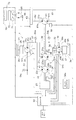
- FIG. 2 is a diagram showing a system including a bulldozer hydraulic and control circuit.
- FIG. 3 is a functional block diagram of the bulldozer controller.
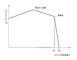
- FIG. 4 is a torque diagram of the engine.
- FIG. 5 is a diagram showing an engine rotation speed, a pump capacity, and a motor capacity in the low-speed matching process.
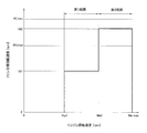
- FIG. 6 is a diagram illustrating a relationship between the engine rotation speed and the fan target rotation speed.
- FIG. 7 is a diagram showing the relationship between the target pump capacity of the fan variable capacity pump and the command current value to the electromagnetic switching valve.
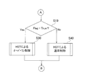
- FIG. 8 is a flowchart of an overrun control method using a bulldozer according to an embodiment.
- FIG. 8 is a flowchart of an overrun control method using a bulldozer according to an embodiment.
- FIG. 9 is a flowchart of an overrun control method using a bulldozer according to an embodiment.
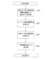
- FIG. 10 is a flowchart of an overrun control method using a hydrostatic transmission.
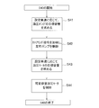
- FIG. 11 is a flowchart of a normal motor / pump control method using a hydrostatic transmission.
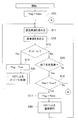
- FIG. 12 is a flowchart of a cooling fan rotation speed control method according to an embodiment.
- a work vehicle according to an embodiment of the present invention is a work vehicle equipped with a hydrostatic transmission, such as a bulldozer.
- a bulldozer will be described as an example of a work vehicle equipped with a hydrostatic transmission.
- rotational speed used in the following embodiments is used in the same meaning as the rotational speed used by those skilled in the art. In other words, the sign of the rotation speed is not considered to be positive or negative.
- FIG. 1 is a side view of a bulldozer 1 according to an embodiment of the present invention.
- the front-rear direction means the front-rear direction of the bulldozer 1.
- the front-rear direction means the front-rear direction viewed from an operator seated in the cab (operator's cab) 7.
- the left-right direction or the side means the vehicle width direction of the bulldozer 1.
- the left-right direction, the vehicle width direction, or the side means the left-right direction viewed from the above-described operator.
- the bulldozer 1 includes a work machine 2, a traveling device 3, and a vehicle body 4.
- the work machine 2 includes a blade 5 and a hydraulic cylinder 6.
- the blade 5 is disposed in front of the vehicle body 4.
- the hydraulic cylinder 6 is driven by hydraulic pressure generated by a hydraulic pump (not shown), and moves the blade 5 up and down.
- the traveling device 3 is a device for traveling the vehicle, and has a pair of crawler belts 3a and a heel 3b.
- the traveling device 3 is connected to a hydrostatic transmission described later.
- the bulldozer 1 travels by driving the crawler belt 3a and the heel 3b. In FIG. 1, only the crawler belt 3a is displayed, and the crawler belt 3b is displayed in FIG.
- the vehicle main body 4 has a cab (operating cab) 7, an engine compartment 8, and a cooling device 70.
- the cab 7 is disposed behind the engine compartment 8.
- the cab 7 includes a seat and an operation device (not shown).
- An engine 20 is stored in the engine chamber 8.
- the cooling device 70 is disposed behind and below the cab 7.
- the cooling device 70 is disposed in the vicinity of the cab 7.
- FIG. 2 shows an outline of a system mainly including a hydraulic circuit of the vehicle.
- the output shaft of the engine 20 is connected to the drive shafts of the left and right travel variable displacement pumps 21 and 22 and the drive shaft of the fan variable displacement pump 61. That is, the variable displacement pumps 21, 22 and 61 are driven by the engine 20.
- the tilt positions (tilt angles) of the swash plates 21a and 22a of the left and right variable displacement pumps 21 and 22 are driven by the left and right pump swash plate driving units 23 and 24, respectively.
- the tilt position (tilt angle) of the fan variable displacement pump 61 is driven by the fan pump swash plate drive unit 69.
- the sprockets 25, 26 for driving the left and right crawler belts 3a, 3b are connected to the drive shafts of the left and right variable displacement hydraulic motors 30, 31 via left and right final reduction gears 27, 28, respectively.
- the left and right traveling variable displacement hydraulic motors 30 and 31 drive the left and right sprockets 25 and 26, respectively.
- the tilt positions (tilt angles) of the swash plates 30a and 31a of the left and right variable displacement hydraulic motors 30 and 31 are driven by the left and right motor swash plate driving units 32 and 33, respectively.
- the left and right variable displacement hydraulic motors 30 and 31 and the left and right variable displacement pumps 21 and 22 form a hydrostatic transmission.
- the left and right brake devices 34 and 35 for stopping the rotation of the hydraulic motors 30 and 31 are provided on the drive shafts of the left and right variable displacement hydraulic motors 30 and 31, respectively.
- the inflow / outflow ports 30b and 30c of the left variable displacement hydraulic motor 30 are connected to the discharge suction ports 21b and 21c of the left variable displacement pump 21 through an oil passage 38 and an oil passage 39, respectively. That is, the left variable displacement hydraulic motor 30 is rotated by the pressure oil of the variable displacement pump 21.
- the inflow / outlet ports 31b and 31c of the right variable displacement hydraulic motor 31 are connected to the discharge suction ports 22b and 22c of the right variable displacement pump 22 via the oil passage 40 and the oil passage 41, respectively. That is, the right variable displacement hydraulic motor 31 is rotated by the pressure oil of the variable displacement pump 22.
- the cooling device 70 includes a cooling fan 71, an oil cooler 72, and a radiator 73.
- the cooling fan 71 sends cooling air to the oil cooler 72 and the radiator 73.
- the cooling fan 71 is connected to a drive shaft of a fixed capacity hydraulic motor 65.
- the hydraulic motor 65 is connected to the electromagnetic switching valve 63 via the oil passages 64 and 66.
- the input port of the electromagnetic switching valve 63 is connected to the outflow port 61 b of the variable capacity pump 61 for the fan via the oil passage 62.
- the output port of the electromagnetic switching valve 63 is connected to the inflow port 61 c of the variable capacity pump 61 for the fan via the oil passage 67. Therefore, the hydraulic motor 65 is rotated by the pressure oil of the variable displacement pump 61.
- the electromagnetic switching valve 63 receives a current command signal from the controller 50, controls the hydraulic flow rate output to the hydraulic motor 65, and controls the rotational speed of the hydraulic motor 65, that is, the cooling fan 71.
- the oil cooler 72 supplies hydraulic oil that circulates through the oil passages 38 and 39, hydraulic oil that circulates through the oil passages 40 and 41, and hydraulic oil that circulates through the oil passages 62, 64, 66, and 67 via an oil passage (not shown). Cooling.
- the radiator 11 cools the refrigerant of the engine 20.
- the controller 50 includes an engine rotation speed sensor 55 that detects the rotation speed of the engine 20, a left rotation speed sensor 56 that detects the rotation speed of the output shaft of the left variable displacement hydraulic motor 30, and a right variable displacement hydraulic pressure.
- a right rotation speed sensor 57 that detects the rotation speed of the output shaft of the motor 31, a sensor 54 a that detects the hydraulic pressure supplied to the right traveling apparatus 3 during forward movement, and a hydraulic pressure that is supplied to the left traveling apparatus 3 during forward movement.
- Signals are input from various sensors including a sensor 54b, a sensor 54c that detects hydraulic pressure supplied to the right traveling device 3 during reverse travel, and a sensor 54d that detects hydraulic pressure supplied to the left traveling device 3 during reverse travel. .
- the plate driving unit 69 and the electromagnetic switching valve 63 are controlled.
- controller 50 transmits an engine rotation speed command signal to the engine controller 50a based on signals from various sensors, and the engine controller 50a controls the engine 20 based on the engine rotation speed command signal.
- FIG. 3 shows a control block diagram of the vehicle.
- various sensors connected to the controller 50 are shown, and the functions of the controller 50 are shown in blocks.
- the controller 50 includes a steering lever sensor 51 in addition to the engine rotational speed sensor 55, the left rotational speed sensor 56, the right rotational speed sensor 57, and the pressure sensors 54a to 54d that detect the pressure in each oil passage shown in FIG.
- a shift up / shift down button sensor 52 and a forward / backward lever sensor 53 are connected.
- the steering lever sensor 51 is a sensor for detecting an operation stroke to the left or right of the steering lever by the operator.
- the steering lever sensor 51 outputs a left / right steering command corresponding to the operation stroke.
- the shift-up / shift-down sensor 52 is a sensor for detecting that the operator has operated a button for up-shifting or down-shifting, and thereby detects a gear position designated by the operator.
- the forward / backward lever sensor 53 is a sensor for detecting whether the operator has instructed forward movement or reverse movement.
- the forward / reverse lever sensor 53 outputs a forward / reverse command for instructing forward or reverse travel.
- the controller 50 includes an arithmetic device such as a CPU and a storage device such as a RAM and a ROM. In the following description, the controller 50 may be called a control unit.
- the controller 50 includes a speed stage setting unit 80, a vehicle speed setting unit 81, a low rotation matching setting unit 82, a pump control unit 83, a motor control unit 86, a traction force calculation unit 91, a vehicle speed measurement unit 92, A run determination unit 93, an overrun state detection unit 94, and a fan control unit 95 are provided.
- the pump control unit 83 includes a pump capacity setting unit 84 and a pump capacity distribution unit 85.
- the fan control unit 95 includes a fan rotation speed setting unit 96, a fan pump control unit 97, and an electromagnetic valve control unit 98.
- the controller 50 typically stores a program and data for executing each of these functions in a storage device. And the controller 50 performs each of these functions, when an arithmetic unit runs the said program.
- the controller 50 may be realized by an integrated circuit.
- the speed stage setting unit 80 receives a signal from the up / down button sensor 52, sets the speed stage, and outputs the set speed stage to the vehicle speed setting unit 81 as a speed stage command.
- a shift mode capable of quick shifting for example, shifting in three steps
- a shift mode capable of fine shifting for example, shifting in 19 steps
- the speed stage is set according to the shift mode and according to the setting of the shift button of the operator.
- the vehicle speed setting unit 81 includes a set vehicle speed table T1, and sets the vehicle speed (the maximum vehicle speed at the set speed stage) based on the speed stage command and the forward / reverse command.
- the vehicle speed set by the vehicle speed setting unit 81 is referred to as a set vehicle speed.
- the set vehicle speed table T1 includes a table for forward travel and a table for reverse travel.
- the set vehicle speed table T1 is stored in the storage device described above.
- the high idle rotational speed means the maximum rotational speed Nhi [rpm] of the engine at no load shown in FIG.
- the low-rotation matching setting unit 82 has a rotational speed N0 lower than the high idle rotational speed Nhi [rpm] until the set vehicle speed is 0 to V2 [km / h].
- An engine control signal is output so as to rotate the engine 20 at [rpm].
- an engine control signal is output so as to increase the engine speed to a high idle speed in proportion to the set vehicle speed.
- a set vehicle speed rotation speed table T2
- a set vehicle speed pump capacity table T3 described later
- the pump capacity distribution unit 85 receives the pump capacity output from the pump capacity setting unit 84 and steering commands from the left and right steering levers and the forward / reverse lever.
- the steering command represents the ratio of the pump displacements of the left and right variable displacement pumps 21 and 22 corresponding to the steering lever and the forward / reverse lever.
- the pump capacity distribution unit 85 takes the steering command into account, converts the set pump capacity into a current command, and outputs the current command as a control signal to the left and right pump swash plate driving units 23 and 24.
- the motor control unit 86 in a state where the overrun control described later is not performed, the motor control unit 86 until the pump capacity becomes maximum, that is, until the set vehicle speed becomes, for example, V1 [km / h].
- the motor capacity Mq is maintained at a constant capacity Mqmax, and after the pump capacity reaches the maximum capacity Pqmax, the motor capacity Mq is gradually decreased as the set vehicle speed increases.
- the motor control unit 86 converts the motor capacity Mq thus obtained into a current command and outputs it as a control signal to the left and right motor swash plate driving units 32 and 33.
- the set vehicle speed rotation speed table T2
- the set vehicle speed pump capacity table T3
- the pump displacement Pq and the motor displacement Mq are set so that the set vehicle speed is obtained when the engine 20 rotates at the rotation speed N0 [rpm] in the low / medium speed region.
- the region where the set vehicle speed is relatively low is a pump region in which the vehicle speed is changed by changing the pump capacity while the motor capacity is maximized.
- the region where the set vehicle speed is relatively high is a motor region in which the vehicle speed is changed by changing the motor capacity while keeping the pump capacity at the maximum.
- the high speed region is a region where the set vehicle speed cannot be reached by control of the variable displacement pump and variable displacement hydraulic motor. Therefore, in the high speed region, as described above, the engine rotational speed is increased to the high idle rotational speed in proportion to the set vehicle speed, and the vehicle speed is changed by controlling the engine rotational speed.
- the traction force measuring unit 91 measures the traction force of the bulldozer 1 based on the detection results from the forward / reverse lever sensor 53 and the pressure sensors 54a to 54d.
- the vehicle speed measuring unit 92 calculates the rotation speed of the output shaft of the left variable displacement hydraulic motor 30 obtained from the left rotation speed sensor 56 and the rotation speed of the output shaft of the right variable displacement hydraulic motor 31 obtained from the right rotation speed sensor 57.
- the actual vehicle speed of the bulldozer 1 is measured by calculating the actual vehicle speed by multiplying the lower rotational speed by the diameter of the sprockets 25 and 26 and the circumference ratio.
- the overrun determination unit 93 compares the actual vehicle speed of the bulldozer 1 with the set vehicle speed to determine whether or not overrun control is necessary.
- the overrun control is control that suppresses the actual vehicle speed by maximizing the pump capacity of the variable displacement pumps 21 and 22 in an overrun state in which the actual vehicle speed of the bulldozer 1 greatly exceeds the set vehicle speed.
- the overrun determination unit 93 (1) the actual vehicle speed measured by the vehicle speed measurement unit 92 is equal to or lower than the overrun control end vehicle speed set by the motor control unit 86 described later, or (2) the traction force is slightly less than zero. In a case where a predetermined time or more elapses that is greater than the small predetermined threshold, it may be determined that the bulldozer 1 is not overrun.
- the overrun determination unit 93 outputs an overrun flag describing the determination result to the pump capacity setting unit 84, the motor control unit 86, and the fan rotation speed setting unit 96.
- the overrun flag is set to True.
- the overrun determination unit 93 determines that the bulldozer 1 is not overrun, the overrun flag is set to False.
- the motor control unit 86 obtains an overrun control target vehicle speed for the set vehicle speed obtained by the vehicle speed setting unit 81. For example, the motor control unit 86 may obtain the overrun control target vehicle speed with reference to a predetermined table. Alternatively, the motor control unit 86 may calculate the overrun control target vehicle speed by comparing the set vehicle speed with the actual vehicle speed.
- the motor control unit 86 controls the variable displacement hydraulic motors 30 and 31 so that the displacements of the variable displacement hydraulic motors 30 and 31 become the target displacements. That is, the motor control unit 86 controls the motor swash plate driving units 32 and 33 of the variable capacity hydraulic motors 30 and 31 so that the capacity of the variable capacity hydraulic motors 30 and 31 becomes the target capacity.
- the overrun state detection unit 94 detects an overrun state under the situation where the overrun control described above is performed. Specifically, the overrun state detection unit 94 determines whether the engine rotation speed detected by the engine rotation speed sensor 55 belongs to the first range, the second range, or the first range or the second range. To determine whether it belongs to. As shown in FIG. 6, the first range is a range where the engine rotation speed is greater than or equal to Ne1 [rpm] and less than Ne2 [rpm]. The second range is a range where the engine rotation speed is greater than or equal to Ne2 [rpm] and less than Ne_max [rpm] which is the limit rotation speed of the engine 20.
- the overrun state detection unit 94 detects a state where the engine rotation speed belongs to the first range or the second range as an overrun state.
- Ne1 [rpm] is a predetermined constant value, and Ne1 [rpm] may be referred to as a first threshold value or a first engine rotation speed.
- Ne2 [rpm] is a predetermined constant value, and Ne2 [rpm] may be referred to as a second threshold value or a second engine rotation speed.
- Ne1 [rpm] is larger than the rated rotational speed Nr [rpm] of the engine 20.
- the rated rotational speed is the rotational speed of the engine 20 at a rated point at which the engine 20 has a rated output.
- Ne1 [rpm] is larger than N0 [rpm] described above.
- the difference between the minimum value Ne2 [rpm] in the second range and the minimum value Ne1 [rpm] in the first range is not less than 50 rpm and not more than 300 rpm.
- the fan control unit 95 controls the fan variable capacity pump 61 and the hydraulic motor 65 so that the rotation speed of the cooling fan 71 becomes the first rotation speed Nf1 when the engine rotation speed belongs to the first range.
- the fan control unit 95 controls the variable displacement pump 61 for the fan and the hydraulic motor 65 so that the rotation speed of the cooling fan 71 becomes the second rotation speed Nf2 when the engine rotation speed belongs to the second range.
- the second rotational speed Nf2 is smaller than Nf_max [rpm], which is the limit rotational speed of the cooling fan 71, but is a value in the vicinity of Nf_max. Further, the second rotation speed Nf2 is higher than the first rotation speed Nf1. The difference between the second rotation speed Nf2 and the first rotation speed Nf1 is not less than 250 rpm and not more than 600 rpm. Thereby, when the cooling fan 71 rotates at the first rotation speed Nf1, it is difficult to generate noise.
- the cooling fan 71 When the engine speed does not belong to either the first range or the second range, that is, when it is smaller than Ne1 [rpm], the cooling fan 71 is controlled normally. That is, as shown in Japanese Patent No. 4285866, when the rotation speed of the cooling fan 71 is within the limit upper limit speed Nfcmax [rpm], the rotation speed according to the refrigerant temperature, engine rotation speed, and hydraulic oil temperature of the engine 20 It is controlled by the fan control unit 95 to be Nf1 is smaller than Nfcmax, and Nf2 is larger than Nfcmax.
- the bulldozer 1 When the bulldozer 1 is operating normally, the engine coolant temperature, engine rotation speed, and hydraulic oil temperature are kept at low values. For this reason, the rotational speed of the cooling fan 71 is normally suppressed to a rotational speed smaller than Nf1. Accordingly, when the overrun state detection unit 94 determines that the engine rotation speed belongs to the first range, the rotation speed of the cooling fan 71 is increased to Nf1 under normal conditions.
- the fan control unit 95 includes a fan rotation speed setting unit 96, a fan pump control unit 97, and a solenoid valve control unit 98.
- the fan rotation speed setting unit 96 sets the rotation speed of the cooling fan 71 to the first rotation speed Nf1 when the engine rotation speed belongs to the first range.
- the fan rotation speed setting unit 96 sets the rotation speed of the cooling fan 71 as the second rotation speed Nf2 when the engine rotation speed belongs to the second range.
- the fan rotation speed setting unit 96 sets the rotation speed of the cooling fan 71 according to the refrigerant temperature of the engine 20, the engine rotation speed, and the hydraulic oil temperature when the engine rotation speed does not belong to either the first range or the second range. Set the rotation speed.
- the fan pump control unit 97 uses the rotation speed Nf of the cooling fan 71 set by the fan rotation speed setting unit 96 and the engine rotation speed Ne detected by the engine rotation speed sensor 55 to obtain the following equation (1). Based on this, the target pump capacity Dp [cc / rev] of the variable capacity pump 61 for the fan is calculated.
- Dp Nf ⁇ Dm / (Ne ⁇ ⁇ ) (1)
- the values of Dm and ⁇ are determined in advance, and the fan pump control unit 97 stores the values of Dm and ⁇ .
- the fan pump control unit 97 calculates the target pump capacity Dp
- the fan pump control unit 97 outputs a control signal to the fan pump swash plate driving unit 69 so that the calculated target pump capacity Dp is obtained.
- the fan pump control unit 97 outputs the obtained target pump capacity Dp to the solenoid valve control unit 98.
- FIG. 7 shows an example of the relationship between the target pump capacity Dp and the command current value I. According to this, as the target pump capacity Dp increases from 0 [cc / rev] to the maximum value Dp_max [cc / rev], the command current value I decreases linearly from I2 [A] to I1 [A]. Yes.
- the electromagnetic valve control unit 98 outputs the obtained command current value I to the electromagnetic switching valve 63 as a control signal.
- the fan control unit 95 sets the rotation speed of the cooling fan 71 to the first rotation speed or the second rotation. End the speed control. In other words, the fan control unit 95 performs the above-described control when the engine speed does not belong to either the first range or the second range.
- Ne1 [rpm] is relatively low so that the cooling fan 71 is controlled to the first rotation speed or the second rotation speed.
- a large value is preset.
- Ne1 [rpm] is larger than the high idle rotation speed Nhi. Therefore, when the overrun state detection unit 94 determines that the engine rotation speed detected by the engine rotation speed sensor 55 belongs to the first range or the second range, the overrun determination unit 93 determines that the bulldozer 1 It is determined to be overrun.
- 8 and 9 are flowcharts of the overrun control method by the bulldozer 1 according to the present embodiment.
- step 10 the overrun determination unit 93 sets False as the initial value of the overrun flag.
- the speed stage setting unit 80 receives a signal from the up / down button sensor 52, sets the speed stage, and outputs the set speed stage to the vehicle speed setting unit 81 as a speed stage command.
- the vehicle speed setting unit 81 obtains a set vehicle speed based on the speed step command and the forward / reverse command from the forward / backward lever sensor 53.
- the overrun determination unit 93 obtains the set vehicle speed from the vehicle speed setting unit 81.
- step 12 the vehicle speed measuring unit 92 determines the rotation speed of the output shaft of the left variable displacement hydraulic motor 30 obtained from the left rotation speed sensor 56 and the output shaft of the right variable displacement hydraulic motor 31 obtained from the right rotation speed sensor 57. Based on the rotational speed, the actual vehicle speed of the bulldozer 1 is measured. The overrun determination unit 93 obtains the actual vehicle speed from the vehicle speed measurement unit 92.
- the overrun determination unit 93 compares the actual vehicle speed with the set vehicle speed to determine whether the bulldozer 1 is overrun. For example, the overrun determination unit 93 determines that the bulldozer 1 is overrun when the actual vehicle speed is equal to or higher than a value obtained by adding a predetermined positive offset to the set vehicle speed.
- the overrun determination unit 93 sets the overrun flag to True (Step 14). Thereafter, in step 30, the pump control unit 83 and the motor control unit 86 perform overrun control based on the fact that the overrun flag is True.
- step 31 in FIG. 10 the pump control unit 83 controls the left and right variable displacement pumps 21 and 22 with the pump displacement as the maximum displacement Pqmax.
- step 32 the motor control unit 86 obtains an overrun control target vehicle speed obtained by adding a predetermined offset of 0 or less to the set vehicle speed.
- step 34 the motor control unit 86 converts the obtained target capacity into a current command and outputs it as a control signal to the left and right motor swash plate driving units 32, 33, whereby the left and right variable capacity hydraulic motors 30, 31 are output. To control.
- the overrun determination unit 93 determines whether or not the overrun control end condition is satisfied. To do. Specifically, a predetermined time or more has elapsed when the actual vehicle speed is equal to or lower than the overrun control end vehicle speed obtained by adding a predetermined offset of 0 or less to the set vehicle speed, or the traction force is greater than a predetermined threshold value slightly smaller than 0. In such a case, it is determined that the end condition is satisfied.
- the overrun determination unit 93 can determine that the traction force is greater than the predetermined threshold based on whether the traction force is equal to or less than the calculated traction force based on the pressure detection results of the hydraulic sensors 54c and 54d.
- Step 16 the overrun determination unit 93 determines whether or not the overrun flag is True. If the end condition is not satisfied (No in Step 15) or the overrun flag is False (No in Step 16), the process proceeds to Step 19 in FIG.
- Step 17 the overrun determination unit 93 sets the overrun flag to False. Thereafter, in step 40, the pump control unit 83 and the motor control unit 86 perform normal control based on the fact that the overrun flag is False.
- the pump capacity distribution section 85 of the pump control section 83 takes into consideration the steering command, converts the set target capacity into a current command, and outputs it as a control signal to the left and right pump swash plate driving sections 23, 24. By doing so, the left and right variable displacement pumps 21, 22 are controlled.
- step 44 the motor control unit 86 converts the obtained target capacity into a current command and outputs it as a control signal to the left and right motor swash plate driving units 32 and 33, whereby the left and right variable capacity hydraulic motors 30 and 31 are output. To control.
- Step 19 in FIG. 8 If the end condition is not satisfied (No in Step 15 in FIG. 8) or the overrun flag is False (No in Step 16 in FIG. 8), the pump control unit 83 and the motor control are performed in Step 19 in FIG.
- the unit 86 refers to the overrun flag. Then, when the overrun flag is True (Yes in step 19 in FIG. 9), the pump control unit 83 and the motor control unit 86 execute the process of step 30 described above. When the overrun flag is False (No in Step 19 of FIG. 9), the pump control unit 83 and the motor control unit 86 execute the process of Step 40 described above.
- FIG. 12 is a flowchart of the rotation speed control method of the cooling fan 71 in the present embodiment.
- the fan control unit 95 refers to the overrun flag set in steps 10, 14, and 17, and determines whether or not the overrun flag is False.
- the overrun flag is True (No in Step 21)
- the engine speed sensor 55 detects the engine speed.
- the overrun state detection unit 94 determines whether the engine rotation speed belongs to the first range, the second range, or neither the first range nor the second range.
- the fan control unit 95 sets the fan variable capacity pump 61 and the hydraulic motor 65 so that the rotation speed of the cooling fan 71 becomes the first rotation speed Nf1. To control.
- the fan control unit 95 sets the fan variable capacity pump 61 and the hydraulic motor 65 so that the rotation speed of the cooling fan 71 becomes the second rotation speed Nf2. To control.
- the fan control unit 95 determines the refrigerant temperature of the engine 20 within the range where the rotational speed of the cooling fan 71 is equal to or lower than the limit upper limit speed Nfcmax.
- the cooling fan 71 is controlled so as to have a rotational speed corresponding to the engine rotational speed and the hydraulic oil temperature.
- the fan control unit 95 executes step 26.
- the overrun determination unit 93 determines that the bulldozer 1 is not overrun. Therefore, when it is determined that the bulldozer 1 is not overrun, the fan control unit 95 ends the control to set the rotation speed of the cooling fan 71 to the first rotation speed Nf1 or the second rotation speed Nf2.
- variable displacement pump 61 that drives the cooling fan 71 is driven by the engine 20 together with the variable displacement pumps 21 and 22 that receive the hydraulic pressure as the traveling device travels.
- the overrun state is detected by the overrun state detection unit 94, the variable displacement pump 61 and the hydraulic motor 65 are controlled so that the rotation speed of the cooling fan 71 increases.
- the load absorbed by the variable displacement pump 61 increases. As a result, the load on the engine 20 is reduced and overrun is prevented.
- the fan rotation speed is controlled to increase stepwise according to the overrun condition. Therefore, the fan sound does not increase when the degree of overrun is relatively small. When the degree of overrun is relatively large, the fan noise does not suddenly increase while reliably preventing overrun. Therefore, operator comfort can be maintained.
- the minimum value (Ne1: first threshold, first engine speed) of the engine speed in the first range is greater than the rated speed Nr [rpm] of the engine 20. More preferably, the first engine rotation speed Ne1 is higher than the high idle rotation speed Nhi. Therefore, when the engine 20 is over-rotated due to overrun, the rotation speed of the cooling fan 71 is increased. Therefore, the fan noise is increased when the overrun is not performed, so that the operator's comfort is further improved.
- the overrun determination unit 93 terminates the overrun control when the pressures of the hydraulic sensors 54d and 54e are equal to or lower than a predetermined pressure. That is, the overrun determination unit 93 ends the control to set the rotation speed of the cooling fan 71 to the first rotation speed Nf1 or the second rotation speed Nf2.
- the pressures of the hydraulic sensors 54d and 54e being equal to or lower than the predetermined pressure means that the traction force has become larger than a predetermined threshold value that is slightly smaller than 0, that is, the force applied backward to the bulldozer 1 has decreased. . Due to the nature of the work performed by the bulldozer 1, the bulldozer 1 enters an overrun state when going backward on the slope.
- the overrun determination unit 93 determines that the bulldozer 1 is not overrun when the actual vehicle speed is equal to or lower than the overrun control end vehicle speed obtained by adding a predetermined offset of 0 or less to the set vehicle speed. Then, the overrun determination unit 93 ends the control for setting the cooling fan 71 to the first rotation speed Nf1 or the second rotation speed Nf2. Since the overrun determination unit 93 can quickly determine that the overrun has ended, the time during which the cooling fan 71 rotates at high speed is reduced.
- the second rotational speed Nf2 of the cooling fan 71 is larger than the upper limit speed limit Nfcmax of the cooling fan 71 when the engine rotational speed is smaller than the first engine rotational speed Ne1.
- the rotation speed of the cooling fan 71 is suppressed so that the cooling fan 71 does not generate noise. Therefore, operator comfort is further improved.
- the difference between the minimum value Ne2 in the second range and the minimum value Ne1 in the first range is not less than 50 rpm and not more than 300 rpm.
- the difference between the second rotation speed Nf2 and the first rotation speed Nf1 is 250 rpm or more and 600 rpm or less.
- the cooling device 70 including the cooling fan 71 is disposed in the vicinity of the rear of the cab 7. Therefore, the noise due to the rotation of the cooling fan 71 greatly affects the operator's comfort.
- the control method of the cooling fan 71 disclosed in this specification is very effective in such a work vehicle.
- cooling device 70 In the above-described embodiment, the example in which the cooling device 70 is disposed behind and below the cab 7 has been described. However, the cooling device 70 may be disposed in front of the cab 7. In addition, when the cooling device 70 is immediately behind the cab 7 as in the above-described embodiment, the sound of the cooling fan 71 that can be heard by the operator seated on the cab 7 is further increased, and thus the present invention is more effective. .
- the rotation speed control of the cooling fan 71 when the engine rotation speed belongs to the two ranges of the first range and the second range has been described.
- the engine rotational speed range may be three or more.
- the fan rotation speed setting unit 96 sets the rotation speed of the cooling fan 71 to a higher rotation speed as the minimum value of each engine rotation speed range increases. It is desirable to do.
- the overrun state detection unit 94 detects an overrun state based on the engine rotation speed.
- the overrun state detection unit 94 may obtain the actual vehicle speed obtained from the left and right rotational speed sensors 56 and 57 and detect the overrun state based on the actual vehicle speed.
- the overrun state detection unit 94 refers to the first vehicle speed corresponding to the first threshold value described above and the second vehicle speed corresponding to the second threshold value described above and higher than the first vehicle speed.
- the detection unit 94 may determine whether the actual vehicle speed belongs to the first range or the second range described above.
- the overrun state detection unit 94 may include the engine rotation speed sensor 55.
- a work vehicle in which overrun can be controlled by another means in a work vehicle equipped with a hydrostatic transmission, even if the capacity increase of the hydraulic pump is limited.
Landscapes
- Engineering & Computer Science (AREA)
- General Engineering & Computer Science (AREA)
- Mining & Mineral Resources (AREA)
- Structural Engineering (AREA)
- Civil Engineering (AREA)
- Mechanical Engineering (AREA)
- Chemical & Material Sciences (AREA)
- Combustion & Propulsion (AREA)
- Transportation (AREA)
- Operation Control Of Excavators (AREA)
- Controls For Constant Speed Travelling (AREA)
- Combined Controls Of Internal Combustion Engines (AREA)
- Control Of Fluid Gearings (AREA)
Abstract
Description
図1は、本発明の一実施形態に係るブルドーザ1の側面図である。なお、以下の説明において、前後方向とは、ブルドーザ1の前後方向を意味する。前後方向とは、キャブ(運転室)7に着座したオペレータから見た前後方向を意味する。また、左右方向、或いは、側方とは、ブルドーザ1の車幅方向を意味する。左右方向、車幅方向、或いは、側方とは、上述のオペレータから見た左右の方向を意味するものとする。
図2に、本車両の主に油圧回路を含むシステムの概略を示している。この図に示すように、エンジン20の出力軸は、左右の走行用の可変容量ポンプ21,22の駆動軸と、ファン用の可変容量ポンプ61の駆動軸とに連結されている。つまり、可変容量ポンプ21,22,61は、エンジン20により駆動される。左右の可変容量ポンプ21,22の斜板21a,22aの傾転位置(傾転角)はそれぞれ、左右のポンプ斜板駆動部23,24によって駆動される。ファン用の可変容量ポンプ61の傾転位置(傾転角)は、ファン用ポンプ斜板駆動部69によって駆動される。
図3に、本車両の制御ブロック図を示す。この図3では、コントローラ50に接続された各種のセンサを示すとともに、コントローラ50の機能をブロック化して示している。
コントローラ50には、上述するエンジン回転速度センサ55、左回転速度センサ56、右回転速度センサ57、図2に示した各油路の圧力を検出する圧力センサ54a~54d以外に、ステアリングレバーセンサ51と、シフトアップ/シフトダウンボタンセンサ52と、前後進用レバーセンサ53とが接続されている。
コントローラ50は、CPUなどの演算装置と、RAM及びROMなどの記憶装置とを含む。以降の説明では、コントローラ50のことを制御部と呼んでもよい。コントローラ50は、速度段設定部80と、車速設定部81と、低回転マッチング設定部82と、ポンプ制御部83と、モータ制御部86と、牽引力演算部91と、車速測定部92と、オーバーラン判定部93と、オーバーラン状態検出部94と、ファン制御部95と、を備えている。
Dm[cc/rev]:油圧モータ65の固定容量
ρ:エンジン20と可変容量ポンプ61の間の減速比
(1)ブルドーザ1では、冷却ファン71を駆動する可変容量ポンプ61は、走行装置の走行によって油圧を受ける可変容量ポンプ21,22とともにエンジン20に駆動される。オーバーラン状態検出部94によってオーバーラン状態が検出されると、冷却ファン71の回転速度が増大するように、可変容量ポンプ61と油圧モータ65とが制御される。このとき、オーバーランにより可変容量ポンプ21,22,61にかかる負荷のうち、可変容量ポンプ61が吸収する負荷が大きくなる。その結果、エンジン20にかかる負荷が減少し、オーバーランが防止される。
本発明は以上のような実施形態に限定されるものではなく、本発明の範囲を逸脱することなく種々の変形又は修正が可能である。
Claims (11)
- エンジンと、
前記エンジンにより駆動されるファン用可変容量ポンプ及び第1走行用可変容量ポンプと、
前記第1走行用可変容量ポンプの圧油により回転する第1走行用可変容量モータと、
前記第1走行用可変容量モータによって駆動される走行装置と、
前記ファン用可変容量ポンプの圧油により回転するファン用モータと、
前記ファン用モータによって駆動されるファンと、
前記走行装置のオーバーラン状態を検出するオーバーラン状態検出部と、
前記オーバーラン状態検出部によって検出された検出値が第1閾値以上になったとき、前記ファンの回転速度を上昇させて、第1ファン回転速度となるように制御し、前記検出値が前記第1閾値より大きい第2閾値以上になったとき、前記ファンの回転速度を前記第1ファン回転速度よりも大きい第2ファン回転速度となるように制御する制御部と、
を備える、
作業車両。 - 前記オーバーラン状態検出部は、前記エンジンの回転速度を検出するエンジン回転速度検出部を含み、
前記検出値は、エンジン回転速度であり、
前記第1閾値は、第1エンジン回転速度であって、
前記第2閾値は、前記第1エンジン回転速度よりも大きい第2エンジン回転速度である、請求項1に記載の作業車両。 - 前記第1エンジン回転速度は、定格回転速度よりも大きい、
請求項2に記載の作業車両。 - 前記第1エンジン回転速度は、ハイアイドル回転速度よりも大きい、
請求項2に記載の作業車両。 - 操作部材から検出された操作信号に基づいて目標車速を設定する車速設定部と、
前記作業車両の実車速を測定する車速測定部と、
をさらに備え、
前記制御部は、前記目標車速以下の車速である所定車速以下と前記実車速がなったとき、前記ファンの回転速度を前記第1ファン回転速度または前記第2ファン回転速度とする制御を終了する、
請求項1から4のいずれかに記載の作業車両。 - 前記第2ファン回転速度は、前記エンジン回転速度が前記第1エンジン回転速度よりも小さいときの前記ファンの上限回転速度よりも大きい、
請求項1から5のいずれかに記載の作業車両。 - 前記第2エンジン回転速度と前記第1エンジン回転速度との差は、50rpm以上300rpm以下である、請求項1から6のいずれかに記載の作業車両。
- 前記第2ファン回転速度と前記第1ファン回転速度との差は、250rpm以上600rpm以下である、請求項1から7のいずれかに記載の作業車両。
- 前記エンジンにより駆動される第2走行用可変容量ポンプと、
前記第2走行用可変容量ポンプの圧油により回転する第2走行用可変容量モータと、
をさらに備え、
前記走行装置は、前記第2走行用可変容量モータによって駆動され、
前記走行装置は、左右の履帯と、前記左右の履帯をそれぞれ駆動する左右のスプロケットを含み、
前記第1走行用可変容量モータは、前記左右のスプロケットのうちの一方を駆動し、
前記第2走行用可変容量モータは、前記左右のスプロケットのうちの他方を駆動する、
請求項1から8のいずれかに記載の作業車両。 - 前記第1ファン回転速度及び前記第2ファン回転速度は、所定の一定値である、
請求項1から9のいずれかに記載の作業車両。 - 前記エンジンの後方に配置されるキャブを備え、
前記ファンは前記キャブの後方近傍に配置されている、
請求項1から10のいずれかに記載の作業車両。
Priority Applications (4)
| Application Number | Priority Date | Filing Date | Title |
|---|---|---|---|
| CN201580000161.3A CN105074157B (zh) | 2015-03-27 | 2015-03-27 | 作业车辆 |
| US14/655,370 US9945101B2 (en) | 2015-03-27 | 2015-03-27 | Work vehicle |
| JP2015516326A JP5978396B2 (ja) | 2015-03-27 | 2015-03-27 | 作業車両 |
| PCT/JP2015/059594 WO2015147255A1 (ja) | 2015-03-27 | 2015-03-27 | 作業車両 |
Applications Claiming Priority (1)
| Application Number | Priority Date | Filing Date | Title |
|---|---|---|---|
| PCT/JP2015/059594 WO2015147255A1 (ja) | 2015-03-27 | 2015-03-27 | 作業車両 |
Publications (1)
| Publication Number | Publication Date |
|---|---|
| WO2015147255A1 true WO2015147255A1 (ja) | 2015-10-01 |
Family
ID=54195759
Family Applications (1)
| Application Number | Title | Priority Date | Filing Date |
|---|---|---|---|
| PCT/JP2015/059594 Ceased WO2015147255A1 (ja) | 2015-03-27 | 2015-03-27 | 作業車両 |
Country Status (4)
| Country | Link |
|---|---|
| US (1) | US9945101B2 (ja) |
| JP (1) | JP5978396B2 (ja) |
| CN (1) | CN105074157B (ja) |
| WO (1) | WO2015147255A1 (ja) |
Cited By (1)
| Publication number | Priority date | Publication date | Assignee | Title |
|---|---|---|---|---|
| JP7658890B2 (ja) | 2021-12-24 | 2025-04-08 | 株式会社クボタ | 作業車両及び作業車両のためのファンの制御方法 |
Families Citing this family (5)
| Publication number | Priority date | Publication date | Assignee | Title |
|---|---|---|---|---|
| JP7490403B2 (ja) * | 2020-03-16 | 2024-05-27 | 株式会社小松製作所 | 作業車両、および作業車両を制御するための方法 |
| US11560826B2 (en) * | 2020-08-15 | 2023-01-24 | Kubota Corporation | Working machine |
| US11793099B2 (en) * | 2020-11-10 | 2023-10-24 | Deere & Company | Harvester implement steering control system to prevent over-running harvester head end during turn |
| CN113586223B (zh) * | 2021-08-27 | 2022-11-29 | 潍柴动力股份有限公司 | 电控硅油风扇的转速控制方法及装置、车辆 |
| WO2025151951A1 (en) * | 2024-01-15 | 2025-07-24 | Prinoth Ltd. | Tracked vehicle |
Citations (4)
| Publication number | Priority date | Publication date | Assignee | Title |
|---|---|---|---|---|
| JP2002528326A (ja) * | 1998-10-22 | 2002-09-03 | フォイト・ターボ・ゲーエムベーハー・ウント・コンパニー・カーゲー | 自動車内のリターダの制動トルク利用を向上させる方法と装置 |
| US20060196179A1 (en) * | 2005-03-01 | 2006-09-07 | Arun Kesavan | Load-sensing integrated brake and fan hydraulic system |
| WO2007074670A1 (ja) * | 2005-12-27 | 2007-07-05 | Hitachi Construction Machinery Co., Ltd. | 油圧作業機のポンプ制御装置、ポンプ制御方法、および建設機械 |
| US20130047955A1 (en) * | 2011-08-31 | 2013-02-28 | Caterpillar Inc. | Retarding system |
Family Cites Families (18)
| Publication number | Priority date | Publication date | Assignee | Title |
|---|---|---|---|---|
| JPS5294637U (ja) | 1976-01-12 | 1977-07-15 | ||
| JPS5732577U (ja) | 1980-07-31 | 1982-02-20 | ||
| JP3351838B2 (ja) | 1992-12-25 | 2002-12-03 | 株式会社小松製作所 | 油圧駆動車のオーバーラン防止方法 |
| JPH0657723U (ja) | 1993-01-20 | 1994-08-12 | 川崎重工業株式会社 | 油圧駆動式車両の車輪駆動機構 |
| JP3432309B2 (ja) | 1994-11-17 | 2003-08-04 | 株式会社四国総合研究所 | 油圧駆動式車両の駆動装置 |
| US5921883A (en) | 1998-05-18 | 1999-07-13 | Cummins Engine Company, Inc. | System for managing engine retarding torque during coast mode operation |
| US8695722B2 (en) | 2003-10-09 | 2014-04-15 | Komatsu Ltd. | Bulldozer with improved visibility |
| AU2005330847B2 (en) * | 2005-04-07 | 2009-07-02 | Hitachi Construction Machinery Co., Ltd. | Cooling device for construction machine |
| US7753152B2 (en) | 2005-09-15 | 2010-07-13 | Komatsu Ltd. | Cooling device for construction machine |
| JP4573751B2 (ja) * | 2005-11-02 | 2010-11-04 | 日立建機株式会社 | 走行式作業機械の冷却ファン駆動装置 |
| JP4847242B2 (ja) * | 2006-07-25 | 2011-12-28 | カヤバ工業株式会社 | ミキサドラム駆動装置 |
| US8985068B2 (en) | 2010-07-22 | 2015-03-24 | Robert Bosch Gmbh | Systems and methods for avoiding resonances excited by rotating components |
| JP5074571B2 (ja) * | 2010-10-26 | 2012-11-14 | 株式会社小松製作所 | 作業車両および作業車両の制御方法 |
| US20130213023A1 (en) * | 2012-02-22 | 2013-08-22 | Peter K. Eckstein | Hydraulic system having low-speed operating mode |
| JP5325316B1 (ja) | 2012-04-24 | 2013-10-23 | 株式会社小松製作所 | ブルドーザ |
| JP5939972B2 (ja) | 2012-12-12 | 2016-06-29 | 日立建機株式会社 | 作業機械 |
| CN103075238A (zh) | 2013-01-23 | 2013-05-01 | 中国重汽集团济南动力有限公司 | Can信息综合控制液压风扇冷却系统 |
| JP5719092B1 (ja) * | 2014-08-25 | 2015-05-13 | 株式会社小松製作所 | ブルドーザ |
-
2015
- 2015-03-27 CN CN201580000161.3A patent/CN105074157B/zh active Active
- 2015-03-27 WO PCT/JP2015/059594 patent/WO2015147255A1/ja not_active Ceased
- 2015-03-27 JP JP2015516326A patent/JP5978396B2/ja active Active
- 2015-03-27 US US14/655,370 patent/US9945101B2/en active Active
Patent Citations (4)
| Publication number | Priority date | Publication date | Assignee | Title |
|---|---|---|---|---|
| JP2002528326A (ja) * | 1998-10-22 | 2002-09-03 | フォイト・ターボ・ゲーエムベーハー・ウント・コンパニー・カーゲー | 自動車内のリターダの制動トルク利用を向上させる方法と装置 |
| US20060196179A1 (en) * | 2005-03-01 | 2006-09-07 | Arun Kesavan | Load-sensing integrated brake and fan hydraulic system |
| WO2007074670A1 (ja) * | 2005-12-27 | 2007-07-05 | Hitachi Construction Machinery Co., Ltd. | 油圧作業機のポンプ制御装置、ポンプ制御方法、および建設機械 |
| US20130047955A1 (en) * | 2011-08-31 | 2013-02-28 | Caterpillar Inc. | Retarding system |
Cited By (1)
| Publication number | Priority date | Publication date | Assignee | Title |
|---|---|---|---|---|
| JP7658890B2 (ja) | 2021-12-24 | 2025-04-08 | 株式会社クボタ | 作業車両及び作業車両のためのファンの制御方法 |
Also Published As
| Publication number | Publication date |
|---|---|
| CN105074157B (zh) | 2017-09-26 |
| CN105074157A (zh) | 2015-11-18 |
| US9945101B2 (en) | 2018-04-17 |
| JPWO2015147255A1 (ja) | 2017-04-13 |
| US20160281328A1 (en) | 2016-09-29 |
| JP5978396B2 (ja) | 2016-08-24 |
Similar Documents
| Publication | Publication Date | Title |
|---|---|---|
| JP5978396B2 (ja) | 作業車両 | |
| JP5092069B1 (ja) | ホイールローダ及びホイールローダの制御方法 | |
| US10011273B2 (en) | Work vehicle and method for controlling same | |
| JP5036824B2 (ja) | 作業車両の原動機制御装置 | |
| CN102245940B (zh) | 静液压式变速车辆的控制装置 | |
| JP5161380B1 (ja) | 作業車両及び作業車両の制御方法 | |
| JP5046690B2 (ja) | 作業車両の制御装置 | |
| JP5192601B1 (ja) | 作業車両及び作業車両の制御方法 | |
| CN101002010B (zh) | 轮式装载机的发动机的负载控制装置 | |
| JP5092071B1 (ja) | ホイールローダ及びホイールローダの制御方法 | |
| CN110914503B (zh) | 作业车辆以及作业车辆的控制方法 | |
| US9435104B2 (en) | Drive system having operator-selectable control modes | |
| JP5092061B1 (ja) | 作業車両及び作業車両の制御方法 | |
| JP2011001896A (ja) | 作業車両の制御装置 | |
| WO2013145341A1 (ja) | ホイールローダ及びホイールローダの制御方法 | |
| JP2012229790A (ja) | 作業車両の制御装置およびその制御方法 | |
| KR101664973B1 (ko) | 작업 차량의 제어장치 | |
| WO2020250862A1 (ja) | 作業車両の制御装置、作業車両、および作業車両の制御方法 | |
| JP4922795B2 (ja) | 作業車両の走行制御装置 | |
| JP6258593B2 (ja) | 作業車両の自動変速装置 | |
| JP2014181804A (ja) | 作業車両の自動変速装置 | |
| CN113795630A (zh) | 作业车辆以及作业车辆的控制方法 |
Legal Events
| Date | Code | Title | Description |
|---|---|---|---|
| WWE | Wipo information: entry into national phase |
Ref document number: 201580000161.3 Country of ref document: CN |
|
| ENP | Entry into the national phase |
Ref document number: 2015516326 Country of ref document: JP Kind code of ref document: A |
|
| WWE | Wipo information: entry into national phase |
Ref document number: 14655370 Country of ref document: US |
|
| 121 | Ep: the epo has been informed by wipo that ep was designated in this application |
Ref document number: 15767705 Country of ref document: EP Kind code of ref document: A1 |
|
| NENP | Non-entry into the national phase |
Ref country code: DE |
|
| 122 | Ep: pct application non-entry in european phase |
Ref document number: 15767705 Country of ref document: EP Kind code of ref document: A1 |