WO2015146061A1 - 車両用認知通知装置、車両用認知通知システム - Google Patents
車両用認知通知装置、車両用認知通知システム Download PDFInfo
- Publication number
- WO2015146061A1 WO2015146061A1 PCT/JP2015/001446 JP2015001446W WO2015146061A1 WO 2015146061 A1 WO2015146061 A1 WO 2015146061A1 JP 2015001446 W JP2015001446 W JP 2015001446W WO 2015146061 A1 WO2015146061 A1 WO 2015146061A1
- Authority
- WO
- WIPO (PCT)
- Prior art keywords
- vehicle
- driver
- recognition
- host
- unit
- Prior art date
- Legal status (The legal status is an assumption and is not a legal conclusion. Google has not performed a legal analysis and makes no representation as to the accuracy of the status listed.)
- Ceased
Links
Images


Classifications
-
- G—PHYSICS
- G08—SIGNALLING
- G08G—TRAFFIC CONTROL SYSTEMS
- G08G1/00—Traffic control systems for road vehicles
- G08G1/16—Anti-collision systems
- G08G1/161—Decentralised systems, e.g. inter-vehicle communication
- G08G1/163—Decentralised systems, e.g. inter-vehicle communication involving continuous checking
-
- G—PHYSICS
- G08—SIGNALLING
- G08G—TRAFFIC CONTROL SYSTEMS
- G08G1/00—Traffic control systems for road vehicles
- G08G1/09—Arrangements for giving variable traffic instructions
-
- G—PHYSICS
- G08—SIGNALLING
- G08G—TRAFFIC CONTROL SYSTEMS
- G08G1/00—Traffic control systems for road vehicles
- G08G1/123—Traffic control systems for road vehicles indicating the position of vehicles, e.g. scheduled vehicles; Managing passenger vehicles circulating according to a fixed timetable, e.g. buses, trains, trams
- G08G1/133—Traffic control systems for road vehicles indicating the position of vehicles, e.g. scheduled vehicles; Managing passenger vehicles circulating according to a fixed timetable, e.g. buses, trains, trams within the vehicle ; Indicators inside the vehicles or at stops
-
- G—PHYSICS
- G08—SIGNALLING
- G08G—TRAFFIC CONTROL SYSTEMS
- G08G1/00—Traffic control systems for road vehicles
- G08G1/16—Anti-collision systems
Definitions
- the present disclosure relates to a vehicle recognition notification device and a vehicle recognition notification system.
- Patent Document 1 discloses a vehicle recognition support system that displays on a display device a symbol indicating the presence of another vehicle sharing position information with the host vehicle and a map image indicating the current position of the other vehicle. Has been. According to this vehicle recognition support system, it is possible to assist the driver of the host vehicle to recognize the presence of the other vehicle.
- the display device of the other vehicle includes A symbol indicating the presence and a map image indicating the current position of the host vehicle are displayed. Therefore, according to the vehicle recognition support system disclosed in Patent Document 1, it is possible to assist the driver of another vehicle to recognize the host vehicle.
- This indication is made based on this situation, and the object is to recognize that the driver of the own vehicle can recognize that the driver of the other vehicle recognizes the own vehicle. And it is providing the recognition notification system for vehicles.
- the recognition notification device for a vehicle is received on a recognition information that is mounted on the own vehicle and receives a signal transmitted from the other vehicle and indicating that the driver of the other vehicle recognizes the own vehicle.
- a notification control unit that notifies the driver of the host vehicle that the driver of the other vehicle recognizes the host vehicle is provided.
- the recognition information reception processing unit of the present disclosure when receiving a signal transmitted from another vehicle and indicating that the driver of the other vehicle recognizes the own vehicle, the notification control unit That the driver of the vehicle recognizes the vehicle. That is, according to the above configuration, the driver of the host vehicle can recognize that the driver of the other vehicle recognizes the host vehicle.
- the first vehicle recognition notification device mounted on the first vehicle and the second vehicle recognition notification device mounted on the second vehicle.
- a first vehicle recognition / notification system wherein the first vehicle recognition / notification device determines whether or not the driver of the first vehicle recognizes the second vehicle;
- the recognition state determination unit determines that the driver of the first vehicle recognizes the second vehicle
- a signal indicating that the driver of the first vehicle recognizes the second vehicle is transmitted to the second vehicle.
- the second vehicle recognition notification device receives the signal transmitted from the first vehicle, and the recognition information reception processing unit receives the signal.
- the first vehicle driver recognizes the second vehicle That it is provided with a notification control unit for notifying the second vehicle driver, a.
- the notification control unit when receiving a signal transmitted from another vehicle and indicating that the driver of the other vehicle recognizes the host vehicle, the notification control unit That the driver of the vehicle recognizes the vehicle. That is, according to the above configuration, the driver of the host vehicle can recognize that the driver of the other vehicle recognizes the host vehicle.
- FIG. 1 is a diagram illustrating an example of a schematic configuration of a vehicle recognition notification system according to the present embodiment.
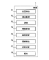
- FIG. 2 is a block diagram illustrating an example of a schematic configuration of the in-vehicle system in the present embodiment.
- FIG. 3A is a block diagram illustrating an example of a schematic configuration of a control unit according to the present embodiment.
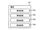
- FIG. 3B is a block diagram illustrating an example of a schematic configuration of a communication processing unit according to the present embodiment.
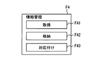
- FIG. 3C is a block diagram illustrating an example of a schematic configuration of a vehicle information management unit according to the present embodiment.
- FIG. 1 is a diagram illustrating an example of a schematic configuration of a vehicle recognition notification system according to the present embodiment.
- FIG. 2 is a block diagram illustrating an example of a schematic configuration of the in-vehicle system in the present embodiment.
- FIG. 3A is a block diagram illustrating an example of a schematic configuration of a control unit according to the present embodiment.
- FIG. 3D is a block diagram illustrating an example of a schematic configuration of a recognition state determination unit according to the present embodiment.
- FIG. 4 is a diagram for explaining an example of the data structure of the surrounding vehicle list stored in the memory.
- FIG. 5 is a flowchart illustrating an example of a target vehicle setting process performed by the control unit.
- FIG. 6 is a flowchart illustrating an example of another driver recognition state determination process performed by the control unit.
- FIG. 7 is a flowchart illustrating an example of the cognitive information transmission related process performed by the control unit.
- FIG. 8 is a flowchart illustrating an example of the self-driver recognition state determination process performed by the self-driver recognition state determination unit.
- FIG. 10A is a block diagram illustrating an example of a schematic configuration of a control unit according to Modification 1.
- FIG. 10B is a block diagram illustrating an example of a schematic configuration of a positional relationship change detection unit in the first modification.
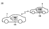
- FIG. 1 is a diagram illustrating an example of a schematic configuration of a vehicular recognition notification system 100 according to the present embodiment.
- the vehicle recognition notification system 100 includes in-vehicle systems 10A and 10B mounted on each of a plurality of vehicles A and B as shown in FIG.
- the in-vehicle systems 10A and 10B installed in each vehicle have the same function, and will be referred to as the in-vehicle system 10 when they are not distinguished from each other hereinafter.
- any one vehicle equipped with the in-vehicle system 10 is referred to as a host vehicle.
- the relationship between the host vehicle and other vehicles is relatively determined.
- the vehicle A is the own vehicle in FIG. 1
- the vehicle B is another vehicle.
- the vehicle A corresponds to the first vehicle of the present disclosure
- the vehicle B corresponds to the second vehicle of the present disclosure.
- the details of the configuration of the in-vehicle system 10 will be described.
- the in-vehicle system 10 includes a control unit 1 (also referred to as a sequential control unit), a communication device 2, a periphery monitoring system 3, an in-vehicle sensor group 4, a driver monitor 5, a display device 6, an audio output device 7, and An input device 8 is provided.
- the control unit 1, the communication device 2, the periphery monitoring system 3, the in-vehicle sensor group 4, the driver monitor 5, the display device 6, the audio output device 7, and the input device 8 communicate with each other via a well-known in-vehicle communication network. carry out.
- the in-vehicle communication network may be constructed by wired communication or may be constructed by wireless communication. Moreover, it may be constructed by combining them.
- the communication device 2 includes a transmission / reception antenna, and transmits / receives information to / from the communication device 2 of another vehicle existing around the host vehicle by broadcast-type wireless communication not via a communication network. That is, the communication apparatus 2 performs vehicle-to-vehicle communication.
- the inter-vehicle communication is configured to use, for example, a 700 MHz band radio wave, and the range in which the communication device 2 can perform wireless communication is within a few hundred meters centering on the own vehicle.
- the host vehicle sequentially performs inter-vehicle communication with other vehicles existing within a range where wireless communication is possible.
- the frequency band used for inter-vehicle communication may be a frequency band other than the 700 MHz band described above, for example, a frequency such as a 5.8 GHz band, a 2.4 GHz band, or the like.
- the range in which wireless communication can be performed may be appropriately designed.
- a communication partner in inter-vehicle communication can be specified by a vehicle ID included in the transmitted / received information.
- the vehicle ID is an identification code set for each vehicle in order to identify each of the plurality of vehicles.
- the surroundings monitoring system 3 is mounted on the host vehicle, detects obstacles around the own vehicle (that is, other vehicles) based on an instruction from the surrounding monitoring control unit F2 of the control unit 1, and detects the relative position of the detected vehicle. Data indicating the relative speed or the like is output to the control unit 1.
- the detection result of the periphery monitoring system 3 is vehicle information (details will be described later) received from the inter-vehicle communication in order to acquire information (for example, position information and vehicle speed) related to other vehicles around the own vehicle with higher accuracy. And is used in a complementary manner.
- the periphery monitoring system 3 includes a front monitoring unit 31, a rear monitoring unit 32, a right side monitoring unit 33, and a left side monitoring unit 34.
- the front monitoring unit 31 sequentially detects obstacles in front of the host vehicle
- the rear monitoring unit 32 sequentially detects obstacles behind the host vehicle.
- the right side monitoring unit 33 sequentially detects obstacles on the right side of the host vehicle
- the left side monitoring unit 34 sequentially detects obstacles on the left side of the host vehicle.
- the front monitoring unit 31 detects, for example, a front camera that images the front of the host vehicle and an obstacle in front of the host vehicle (here, another vehicle) using a reflected wave obtained by reflection of electromagnetic waves or sound waves. And an object sensor (both not shown).
- the front here refers to the range including not only the front direction of the host vehicle but also the diagonally forward left and the diagonally forward right.
- the front camera is an optical camera, and for example, a CMOS camera or a CCD camera can be used.
- an infrared camera may be used as the front camera.
- the front camera may be installed in the vicinity of a rearview mirror in the vehicle interior so as to capture a predetermined range in front of the host vehicle.
- the front obstacle sensor also determines the distance to the obstacle based on the difference or phase change between the time when the exploration wave is transmitted and the time when the exploration wave is reflected by the object.
- This is a well-known obstacle sensor that detects the direction in which the obstacle exists and the relative speed.
- a millimeter wave radar is employed.
- the front obstacle sensor may be installed in the vicinity of the center of the front bumper so as to transmit a search wave to a predetermined range in front of the host vehicle, for example.
- the front obstacle sensor may be a laser radar, an infrared sensor, or an ultrasonic sensor, or may be a distance measuring system that specifies a position from parallax of images taken by a plurality of cameras. Good.
- the front monitoring unit 31 When the front monitoring unit 31 detects another vehicle from the image captured by the front camera or the detection data detected by the front obstacle sensor, the front monitoring unit 31 gives a specific detected vehicle ID to each other vehicle. The relative position of the other vehicle with respect to the host vehicle, the relative speed, and the like are calculated.
- the front monitoring unit 31 detects another vehicle existing in front of the host vehicle by image recognition using image information of the front camera or the like, the distance to the other vehicle or the other vehicle exists by a front obstacle sensor. Detect direction. And the relative position with respect to the own vehicle of the said other vehicle is calculated by specifying a distance and a direction. A known pattern matching technique or the like may be applied to determine whether or not the detected object is a vehicle.
- the forward monitoring unit 31 can track the other vehicle once detected and given the detected vehicle ID by using a well-known object tracking (tracking) method.
- object tracking tilting
- the front monitoring unit 31 generates data (forward vehicle data) associated with the detected vehicle ID assigned to the other vehicle and the relative position and relative speed of the other vehicle, and sequentially outputs them to the control unit 1. .
- the front monitoring unit 31 may not include a front camera and may detect a distance to another vehicle only by a front obstacle sensor. Moreover, it is good also as a structure which detects another vehicle only by the image of a front camera, without providing a front obstacle sensor.
- the rear monitoring unit 32 detects an obstacle (that is, another vehicle) existing behind the host vehicle by using a rear camera that captures the rear of the host vehicle and a reflected wave obtained by reflection of an exploration wave such as an electromagnetic wave.
- a rear obstacle sensor both not shown.
- the term “rear” as used herein refers to a range including not only the rear direction of the host vehicle but also the diagonally left rear and the diagonally right rear.
- the rear camera and the rear obstacle sensor have the same configuration as the front camera and the front obstacle sensor, except that the installation location and the shooting range (or detection range) are different. That is, the rear camera is an optical camera, and may be installed, for example, at the upper part of the rear window so as to photograph a predetermined range behind the host vehicle.
- the rear obstacle sensor is a millimeter wave radar and is installed so as to form a detection range in a predetermined range behind the host vehicle.
- the rear obstacle sensor may be installed in the vicinity of the center of the rear bumper so as to transmit a search wave to a predetermined range behind the host vehicle, for example.
- the rear monitoring unit 32 also detects another vehicle existing behind the host vehicle from the image captured by the rear camera or the detection data detected by the rear obstacle sensor, the relative position, the relative speed, etc. between the other vehicle and the host vehicle are detected. Is calculated for each other vehicle. Further, the information for each other vehicle is managed by the detected vehicle ID assigned to each other vehicle, similarly to the front monitoring unit 31.
- the rear monitoring unit 32 generates data (rear vehicle data) associated with the detected vehicle ID assigned to the other vehicle and the relative position or relative speed of the other vehicle, and sequentially outputs the data to the control unit 1. .
- the right side monitoring unit 33 uses the time from when the exploration wave is transmitted to when the reflected wave of the exploration wave is received, the distance to the other vehicle on the right side of the host vehicle, and the existence of the other vehicle.
- a right-side obstacle sensor that detects the direction to perform is provided.
- Various obstacle sensors can be employed as the right-side obstacle sensor.
- a configuration using a millimeter wave radar is employed as in the front obstacle sensor and the rear obstacle sensor.
- the right side here includes from the diagonally right front of the host vehicle to the diagonally right rear.
- Information on other vehicles detected by the right-side obstacle sensor is supplied to the control unit 1. More specifically, when the right side monitoring unit 33 detects another vehicle, the right side monitoring unit 33 calculates a relative position, a relative speed, and the like between the other vehicle and the host vehicle for each other vehicle. Similar to the forward monitoring unit 31, the information for each other vehicle is managed by the detected vehicle ID assigned to each other vehicle. Then, the right side monitoring unit 33 generates a detected vehicle ID assigned to the other vehicle and data (right side vehicle data) associated with the relative position and relative speed of the other vehicle, and sequentially transmits them to the control unit 1. Output.
- the left side monitoring unit 34 uses the time from when the exploration wave is transmitted to when the reflected wave of the exploration wave is received, the distance to the other vehicle on the left side of the own vehicle, and the other vehicle exists.
- a left side obstacle sensor for detecting the direction is provided.
- Various obstacle sensors can be employed as the left-side obstacle sensor.
- a millimeter wave radar is employed in the same manner as other obstacle sensors.
- the left side here includes from the left diagonal front to the left diagonal rear of the host vehicle.
- the information of the obstacle detected by the left side obstacle sensor is supplied to the control unit 1. More specifically, when the left side monitoring unit 34 detects another vehicle, the left side monitoring unit 34 calculates a relative position, a relative speed, and the like between the other vehicle and the host vehicle for each other vehicle. Similar to the forward monitoring unit 31, the information for each other vehicle is managed by the detected vehicle ID assigned to each other vehicle. Then, the left side monitoring unit 34 generates data (left side vehicle data) associated with the detected vehicle ID assigned to the other vehicle and the relative position and relative speed of the other vehicle, and sequentially transmits them to the control unit 1. Output.
- the right side monitoring unit 33 and the left side monitoring unit 34 are different from the front monitoring unit 31 and the rear monitoring unit 32 in that the camera is not provided, but the present invention is not limited thereto. That is, the right side monitoring unit 33 and the left side monitoring unit 34 may each include a camera, like the front monitoring unit 31 and the rear monitoring unit 32.
- the front, rear, left side, and right side obstacles may be detected by the omnidirectional obstacle sensor.
- the in-vehicle sensor group 4 is various sensors that are mounted on the host vehicle and detect the state of the host vehicle. For example, a vehicle speed sensor, an acceleration sensor, a gyro sensor, a GNSS receiver, a steering angle sensor, and a brake stroke sensor. , An accelerator pedal sensor, a direction indicating lever position sensor, a door mirror angle sensor, and the like.
- the vehicle speed sensor detects the traveling speed of the host vehicle
- the acceleration sensor detects the acceleration acting on the host vehicle.
- the GNSS receiver acquires data indicating the current position of the GNSS receiver by receiving radio waves from a satellite used in GNSS (Global Navigation Satellite System).
- GNSS Global Navigation Satellite System
- a GPS receiver can be used as the GNSS receiver.
- the gyro sensor detects the rotational angular velocity around the vertical axis of the host vehicle, and the steering angle sensor detects the steering angle based on the steering angle.
- the brake stroke sensor detects the depression amount of the brake pedal, and the accelerator pedal sensor detects the depression amount of the accelerator pedal.
- the direction indicating lever position sensor detects whether the direction indicating lever is in a left turn position or a right turn position.
- the door mirror angle sensor is a sensor for detecting the angle of the mirror surfaces of the left and right door mirrors provided in the host vehicle. Detection values detected by various sensors included in the in-vehicle sensor group 4 are sequentially output to the control unit 1.
- the driver monitor 5 is installed in the interior of the vehicle in a posture in which the photographing surface faces the driver, sequentially captures a range including the driver's face (for example, every 100 milliseconds), and image data of the captured image Are sequentially output to the control unit 1.
- the driver monitor 5 is mounted on the steering column cover, but may be mounted on the rearview mirror portion or the like as another mode.
- an infrared camera capable of capturing an image in an environment with little visible light by detecting infrared rays is used as the driver monitor 5.
- the driver monitor 5 may be an optical camera that senses visible light, such as a CMOS camera or a CCD camera, in addition to the infrared camera. This driver monitor 5 corresponds to the face photographing device of the present disclosure.
- the display device 6 displays texts and images based on instructions from the control unit 1 and notifies the driver of various information.
- the display device 6 is capable of full color display, for example, and can be configured using a liquid crystal display, an organic EL display, a plasma display, or the like.
- the display device 6 is a center display arranged near the center in the vehicle width direction of the instrument panel.
- the display device 6 may be a meter display arranged on the driver seat side of the instrument panel.
- the display device 6 may be a known head-up display that displays various information by projecting a virtual image on a part of the windshield in front of the driver's seat.
- the display device 6 may be realized by combining a center display, a meter display, a head-up display, and the like.
- the control unit 1 may select a display that is an output destination of the data for each data to be displayed.
- the audio output device 7 is composed of a speaker or the like, and converts audio data input from the control unit 1 into audio (including simple sounds) and outputs the audio.
- the input device 8 is a mechanical switch (so-called steering switch) provided on the steering wheel.
- the steering switch as the input device 8 includes a plurality of switches, and each of the plurality of switches is assigned a function according to the preference of the driver.
- the driver can instruct execution of a function corresponding to the operation by operating the input device 8.
- the input device 8 detects an input operation by the driver, the input device 8 outputs a control signal representing the input operation to the control unit 1.
- the input device 8 is configured to employ a steering switch, but is not limited thereto.
- a voice input device realized by using a known voice recognition technique may be used, or a mechanical switch provided on the instrument panel may be used.
- a known touch panel configured integrally with the display device 6 may be used.
- the control unit 1 is configured as a normal computer, and includes a well-known CPU, a non-volatile memory such as a ROM or EEPROM, a flash memory, a volatile memory such as a RAM, an I / O, and a bus line that connects these configurations. (Both not shown) and the like.
- the memory 11 provided in the control unit 1 is a rewritable storage medium, and is realized by, for example, a flash memory or a RAM provided in the control unit 1.
- the memory 11 stores program modules and data for executing various processes. Further, the memory 11 stores a vehicle ID set for the own vehicle and a surrounding vehicle list.
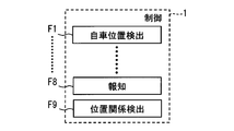
- the control unit 1 includes a host vehicle position detection unit F1, a periphery monitoring control unit F2, a communication processing unit F3, a vehicle information management unit F4, a target vehicle setting unit F5, a line-of-sight detection unit F6, A recognition determination unit F7 and a notification control unit F8 are provided.
- the control unit 1 corresponds to the vehicle recognition notification device of the present disclosure.
- control unit 1A included in the in-vehicle system 10A corresponds to the first vehicle recognition notification device of the present disclosure
- control unit 1B included in the in-vehicle system 10B corresponds to the second vehicle recognition notification device of the present disclosure.
- the own vehicle position detection unit F1 detects the current position of the own vehicle based on signals input from sensors included in the in-vehicle sensor group 4 such as a GNSS receiver, a vehicle speed sensor, and a gyroscope.
- the position information indicating the current position may be configured to be expressed by latitude and longitude, for example.
- the own vehicle position detection unit F1 acquires position information sequentially (for example, every 100 milliseconds).
- the own vehicle position detection unit F1 corresponds to the own vehicle position acquisition unit of the present disclosure.
- the periphery monitoring control unit F2 controls the operation of the above-described periphery monitoring system 3, and acquires information on other vehicles existing around the host vehicle from the periphery monitoring system 3. That is, forward vehicle data is obtained from the front monitoring unit 31, rear vehicle data is obtained from the rear monitoring unit 32, right side vehicle data is obtained from the right side monitoring unit 33, and left side vehicle data is obtained from the left side monitoring unit 34. . And the periphery monitoring control part F2 is based on the data of the other vehicle which exists in each of these directions, and the data (for each other vehicle which exists in the range which can be detected with the periphery monitoring system 3 shows the relative position and relative speed ( Generate peripheral vehicle data).
- the process of specifying the relative position of other vehicles existing in each direction is performed by the monitoring unit corresponding to each direction, and the surrounding monitoring control unit F2 is controlled by each monitoring unit.
- the identified results are collected, but not limited to this.
- the periphery monitoring control unit F2 may implement part or all of the processing for specifying the relative position of other vehicles existing in each direction. That is, the periphery monitoring control unit F2 may sequentially acquire data detected by devices (cameras and obstacle sensors) included in each monitoring unit, and specify the relative position, relative speed, and the like of the surrounding vehicle from those data. .
- the communication processing unit F3 controls the operation of the communication device 2, performs a process of receiving data from other vehicles around the host vehicle, and transmits data to all or a part of the other vehicles. To implement. As shown in FIGS. 3A to 3D, the communication processing unit F3 includes a vehicle information transmission processing unit F31, a vehicle information reception processing unit F32, a recognition information transmission processing unit F33, and a recognition information reception processing unit F34 as detailed functional blocks. Prepare.
- the vehicle information transmission processing unit F31 generates vehicle information including at least the vehicle ID and position information of the own vehicle, and transmits the vehicle information to all other vehicles existing around the own vehicle via the communication device 2.
- the vehicle information may be generated in accordance with a standard format, and may include the traveling direction and vehicle speed of the vehicle in addition to the vehicle ID and position information of the vehicle that is the transmission source.
- the vehicle information includes a transmission source vehicle ID, position information, traveling direction, vehicle speed, and acceleration.
- the vehicle information may include not only the latest position information but also time-series data of position information in which the position information of the vehicle is arranged in time series as the position information of the transmission source.
- the time-series data of the position information indicates the travel locus of the vehicle.
- vehicle information is good also as a structure containing the information for pinpointing a position instead of position information.
- the information for specifying the position is, for example, information indicating a vehicle ID of another vehicle that travels around the transmission source vehicle and a relative position with the vehicle.
- the vehicle information reception process part F32 performs the process which receives the vehicle information which the other vehicle transmitted.
- the vehicle information received from other vehicles is sequentially output to the vehicle information management unit F4.
- the vehicle information transmitted by the other vehicle is also generated according to the same data format as the vehicle information transmitted by the own vehicle. That is, the vehicle information reception processing unit F32 receives vehicle information including the vehicle ID, position information, traveling direction, vehicle speed, and acceleration of the other vehicle from the other vehicle.
- the recognition information transmission processing unit F33 generates a recognition information signal and transmits it to a predetermined other vehicle.
- the recognition information signal is a signal indicating whether or not the driver of the host vehicle recognizes the presence of the other vehicle.
- the recognition information signal includes the vehicle ID of the transmission source, the vehicle ID of the other vehicle as the destination, and the recognition information indicating whether the driver of the host vehicle recognizes the presence of the other vehicle as the destination.
- the configuration is as follows.
- the recognition information may be expressed by, for example, a recognition flag that is a processing flag. More specifically, when the driver of the own vehicle recognizes the presence of the other vehicle, the recognition flag is set to 1, while the driver of the own vehicle does not recognize the presence of the other vehicle. In this case, a recognition information signal with a recognition flag set to 0 may be transmitted.
- the recognition information reception process part F34 performs the process which receives the recognition information signal which the other vehicle transmitted toward the own vehicle. That is, the recognition information signal received from another vehicle indicates whether or not the driver of the transmission source of the recognition information signal recognizes the own vehicle.
- the driver of the own vehicle is also referred to as the own driver and the driver of the other vehicle is referred to as the other driver.
- the communication device 2 of the own vehicle since each vehicle performs broadcast communication by the communication device 2, the communication device 2 of the own vehicle also receives a recognition information signal transmitted toward other than the own vehicle. Therefore, when the recognition information signal is input from the communication device 2, the recognition information reception processing unit F34 collates the destination vehicle ID included in the recognition information signal with the vehicle ID of the host vehicle. Then, as a result of the title, the recognition information signal whose destination vehicle ID is not the ID of the own vehicle is discarded. On the other hand, when the destination vehicle ID is the vehicle ID of the own vehicle, The recognition information signal is passed to the recognition determination unit F7. By setting it as such a structure, it is set as the structure which implements communication with a specific vehicle also in this embodiment.
- the vehicle information management unit F4 manages information on other vehicles existing around the host vehicle.
- the vehicle information management part F4 is provided with the other vehicle information acquisition part F41, the vehicle information storage process part F42, and the periphery vehicle matching part F43 as a finer functional block for implementing the role mentioned above.
- the other vehicle information acquisition unit F41 acquires the vehicle information received from the other vehicle by the vehicle information reception processing unit F32 and also acquires the surrounding vehicle data from the periphery monitoring control unit F2. That is, the other vehicle information acquisition unit F41 acquires information (position information, vehicle speed, etc.) of other vehicles existing around the host vehicle.
- the other vehicle information acquisition unit F41 corresponds to the other vehicle position acquisition unit of the present disclosure.
- the vehicle information storage processing unit F42 stores the vehicle information of the other vehicle acquired by the other vehicle information acquisition unit F41 from the vehicle information reception processing unit F32 in the memory 11 in association with the vehicle ID of the other vehicle of the transmission source.
- the vehicle information storage processing unit F42 of the present embodiment uses the surrounding vehicle list that lists other vehicles that have received the vehicle information, so that the vehicle information of other vehicles that exist around the host vehicle. Manage.
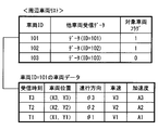
- the surrounding vehicle list includes, for each vehicle ID, other vehicle reception data that lists vehicle information received from the other vehicle, and a target vehicle setting flag.
- the other vehicle reception data is data in which vehicle information received from the other vehicle is arranged in order of reception time, and the vehicle position, traveling direction, vehicle speed, and transmission interval included in the vehicle information received at each time. It has. In addition, what is necessary is just to discard the data with which other vehicle reception data are provided in an old order. Further, the vehicle ID data for which the vehicle information has not been received for a certain period of time is deleted from the surrounding vehicle list. The target vehicle setting flag will be described later.
- the vehicle information storage processing unit F42 also stores the vehicle information of the own vehicle generated by the vehicle information transmission processing unit F31 in the order of the generation time, in the same order as the other vehicle reception data, in the memory 11. Data consisting of the vehicle information of the host vehicle arranged in time series stored in the memory 11 is referred to as host vehicle data.
- the vehicle information storage processing unit F42 sets the data for each other vehicle included in the surrounding vehicle data acquired by the other vehicle information acquisition unit F41 from the surroundings monitoring control unit F2 for each detected vehicle ID associated with the data. And stored in the memory 11.
- the data for each detected vehicle ID is hereinafter referred to as other vehicle detection data.
- the other vehicle detection data is data in which the results of detection by the periphery monitoring system 3 such as the relative position and relative speed of the other vehicle with respect to the host vehicle are arranged in order of detection time.
- the relative position of the other vehicle with respect to the host vehicle detected by the periphery monitoring system 3 is referred to as a detected relative position
- the relative speed thereof is referred to as a detected relative speed.
- the surrounding vehicle associating unit F43 detects the other vehicle (detected by the surrounding monitoring system 3) based on the other vehicle detection data for each detected vehicle ID and the other vehicle received data for each vehicle ID included in the surrounding vehicle list. In other words, the detected vehicle ID) is associated with the vehicle ID.
- the surrounding vehicle associating unit F43 determines the relative position of the other vehicle with respect to the own vehicle (the reception relative position) from the position information included in other vehicle reception data of a certain vehicle ID and the position information of the own vehicle. calculate. And the surrounding vehicle matching part F43 compares the above-mentioned receiving relative position with the detection relative position for every other vehicle, and transmits the vehicle information among the other vehicles detected by the surrounding monitoring system 3. The other vehicle corresponding to the other vehicle is extracted.
- the difference between the detected relative position of the other vehicle and the above-described reception relative position is within a predetermined allowable distance (for example, within 1 m).
- the other vehicle with the detected vehicle ID is determined to be the other vehicle from which the vehicle information used for calculating the reception relative position is transmitted.
- the detected vehicle ID of the other vehicle determined to be applicable is associated with the vehicle ID of the other vehicle that is transmitting the vehicle information used for calculating the reception relative position.
- the association between the other vehicle receiving the vehicle information and the other vehicle detected by the periphery monitoring system 3 is based on the received relative position and the detected relative position at the current time.
- the other vehicle receiving the vehicle information and the periphery monitoring system 3 detect You may perform matching with the other vehicle which exists.
- the time-series data of the reception relative positions at the plurality of time points may be generated based on the other vehicle reception data stored in the memory 11.
- the relative speed, the traveling direction, the acceleration, and the like are used to associate the other vehicle receiving the vehicle information with the other vehicle detected by the periphery monitoring system 3. Also good.
- the relative speed calculated from the vehicle speed included in the vehicle information received from the other vehicle and the vehicle speed of the host vehicle acquired from the in-vehicle sensor group 4 (reception relative position), and each detected vehicle ID Is compared with the detected relative speed stored in, and the difference between the relative speeds is calculated. Then, another vehicle whose difference between the reception relative speed and the detection relative speed is equal to or less than a predetermined threshold and whose difference between the reception relative position and the detection relative position is within a certain distance is It determines with it being the other vehicle which transmitted the vehicle information used for calculation.
- the method of associating the other vehicle receiving the vehicle information with the other vehicle detected by the periphery monitoring system 3 is not limited to the above-described example, and other known methods may be applied. .
- the periphery monitoring system 3 indicates the relative position, relative speed, position information, vehicle speed, and the like of other vehicles for which the association between the vehicle ID and the detected vehicle ID has been completed.
- the detected value is used. That is, the detected relative position and the detected relative speed are adopted as the relative position and the relative speed of the other vehicle, and the position information of the other vehicle is specified from the position information and the detected relative position of the own vehicle detected by the own vehicle position detecting unit F1.
- the vehicle speed of the other vehicle is configured to employ a value obtained from the vehicle speed of the host vehicle and the detected relative speed. The same applies to other parameters such as acceleration.
- the value included in the vehicle information received from the vehicle information is used as the information indicating the running state of the other vehicle. May be.
- values included in the vehicle information from the other vehicle may be adopted as the position information and the vehicle speed of the other vehicle.
- a value included in the vehicle information received from the other vehicle may be adopted, or a value calculated from time series data of the position information of the other vehicle may be adopted. Good.
- the target vehicle setting part F5 sets the other vehicle (referred to as the target vehicle) to be processed in the other driver recognition state determination process and the recognition information transmission related process among the other vehicles receiving the vehicle information ( Target vehicle setting process).
- This target vehicle setting process will be described with reference to the flowchart shown in FIG.
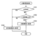
- FIG. 5 is a flowchart showing an example of the target vehicle setting process performed by the target vehicle setting unit F5.
- the target vehicle setting process illustrated in FIG. 5 is configured to be performed when the vehicle information reception processing unit F32 receives vehicle information from another vehicle, for example.
- Whether or not the other vehicle is another vehicle traveling in the oncoming lane may be determined by comparing the traveling direction of the other vehicle included in the received vehicle information with the traveling direction of the host vehicle. For example, when the angle formed by the traveling direction of the other vehicle and the traveling direction of the host vehicle is equal to or greater than a predetermined threshold (referred to as an oncoming vehicle determination threshold), the other vehicle travels in the oncoming lane. Judge that there is.
- the oncoming vehicle determination threshold may be appropriately designed, for example, 170 degrees.
- S101 If it is determined that the other vehicle that transmitted the vehicle information is another vehicle that travels in the oncoming lane, S101 is YES and the process proceeds to S104. On the other hand, when it determines with the other vehicle which transmitted vehicle information being the other vehicle which drive
- a target vehicle setting distance may be a constant value such as 50 m, or may be a value determined according to the vehicle speed of the host vehicle. In the latter case, the target vehicle setting distance is set to be larger as the relative speed with the target vehicle is larger.
- S102 When the other vehicle that has transmitted the vehicle information is within the target vehicle setting distance from the host vehicle, S102 is YES and the process proceeds to S103. On the other hand, when the other vehicle that transmitted the vehicle information does not exist within the target vehicle setting distance from the own vehicle, S102 is NO and the process proceeds to S104.
- the other vehicle is set as the target vehicle, and this flow ends. More specifically, 1 is set to the target vehicle flag of the other vehicle that has transmitted the vehicle information in the surrounding vehicle list.
- the target vehicle flag is a flag for distinguishing between other vehicles that are target vehicles and other vehicles that are not target vehicles (non-target vehicles). For other vehicles that are target vehicles, the target vehicle flag Is set to 1. On the other hand, a vehicle in which the target vehicle flag is set to 0 means a non-target vehicle.
- the other vehicle is set as a non-target vehicle, and this flow ends. That is, in the surrounding vehicle list, 0 is set to the target vehicle flag of the other vehicle that has transmitted the vehicle information.
- the other driver recognition state determination process and the recognition information transmission related process described later are performed by setting in advance whether or not the target vehicle is set as the target vehicle with respect to other vehicles existing around the host vehicle. Can reduce the processing load. That is, the above-described target vehicle setting process is a process for reducing the processing load in the other driver recognition state determination process and the recognition information transmission related process, and is not an essential process.
- the target vehicle and the non-target vehicle are distinguished using the difference in the traveling direction of the host vehicle and the other vehicle or the distance between the host vehicle and the other vehicle.
- the target vehicle and the non-target vehicle may be distinguished using the type of road on which the host vehicle is traveling, the travel route, intersection information, and the like.
- the vehicle that travels in the oncoming lane and the other vehicle that is more than the target vehicle setting distance from the own vehicle are not set as the target vehicle, and the other vehicle is the target vehicle. Yes, but not limited to this. Regardless of the traveling direction, all other vehicles existing within the target vehicle setting distance from the host vehicle may be used as the target vehicle. That is, the flowchart shown in FIG. 5 is an example. The conditions for the target vehicle may be designed as appropriate.
- a vehicle that has no possibility of physically encountering is, for example, a vehicle having a relationship between a vehicle traveling on a city highway and a vehicle traveling on a general road in a section in which the city highway and a general road run side by side. That is, when the host vehicle is traveling on a general road that runs parallel to the expressway, some of the other vehicles traveling on the expressway may have the same traveling direction as the host vehicle. However, it can be said that there is no possibility of physically encountering the own vehicle traveling on a general road and the other vehicle traveling on a highway. Therefore, such a vehicle is preferably set as an asymmetric vehicle.
- Whether or not there is a relationship between a vehicle traveling on an urban highway and a vehicle traveling on a general road may be determined by various methods. For example, when the vehicle information transmitted / received by inter-vehicle communication includes information on the type of road (highway or general road) on which each vehicle is traveling, the information described above is used. What is necessary is just to determine whether it is a vehicle which satisfy
- the vehicle may be in a relationship between a vehicle traveling on an urban highway and a vehicle traveling on a general road, or may be in a different level in a multilevel parking lot In any case, it can be said that there is no possibility of physical encounter.
- the line-of-sight detection unit F6 sequentially acquires image data captured by the driver monitor 5, detects feature points from the image data using a known image processing technique, and detects the face area, the eye area in the face area, and the black eye part. Etc. are detected. Since the driver monitor 5 of the present embodiment is fixedly installed on the host vehicle and the imaging direction is also fixed, the driver's face in the host vehicle is determined according to the position and size of the face area in the image data. Can be specified.
- the gaze detection unit F6 detects the gaze direction of the driver from the size of the face area, the position of the eye area in the face area, and the position of the black eye.
- the recognition determination unit F7 includes an other driver recognition state determination unit F71 and a self-driver recognition state determination unit F72 as finer functional blocks.
- the other driver recognition state determination unit F71 determines the recognition state of the other driver with respect to the host vehicle.
- the other driver recognition state determination part F71 distinguishes the recognition state of the other driver with respect to the own vehicle into three recognized: unrecognized, unrecognized.
- the case where the recognition state of the other driver with respect to the own vehicle is already recognized refers to the case where the other driver recognizes the own vehicle, and the recognition state of the other driver with respect to the own vehicle is not recognized. Indicates a case where another driver has not yet recognized the host vehicle. Further, the case where the recognition state of the other driver with respect to the own vehicle is unknown means that the recognition information signal from the other vehicle has not been received and the information indicating the recognition state of the other driver with respect to the own vehicle (that is, the recognition information). ) Refers to the case where it is not obtained. Thus, the case where the recognition state of the other driver with respect to the own vehicle becomes unknown means the case where the in-vehicle system 10 is not mounted on the other vehicle. The details of the other driver recognition state determination unit F71 will be described in the other driver recognition state determination process.
- the own driver recognition state determination unit F72 determines the recognition state of the own driver with respect to the other vehicle, and causes the recognition information transmission processing unit F33 to generate and transmit recognition information based on the recognition state. Note that the recognition state of the own driver with respect to the other vehicle is expressed by whether or not the own driver recognizes the presence of the other vehicle, that is, either recognized or unrecognized.
- the notification control unit F8 performs a process of notifying the driver of various information via the display device 6 and the audio output device 7. For example, the notification control unit F8 displays information indicating whether or not the driver of the other vehicle recognizes the host vehicle on the display device 6 based on the recognition information signal received from the other vehicle.
- the notification control unit F8 informs the driver that the driver of the host vehicle prompts the driver to visually recognize the direction in which the other vehicle to be notified to the driver is present, and that another vehicle is approaching.
- An image or text to be notified is displayed on the display device 6.
- the other vehicle to be notified to the driver corresponds to an other vehicle that is in the visible range of the host vehicle and is not yet recognized by the driver.
- the notification control unit F8 performs notification to the driver not only through the display device 6 but also through the audio output device 7. Further, the notification control unit F8 may urge the driver of the host vehicle to visually recognize the direction to be watched by turning on an illumination device (not shown) provided on the door mirror. The operation of the notification control unit F8 will be described in the description of the flowcharts shown in FIGS.
- This other driver recognition state determination process is mainly performed by the other driver recognition state determination unit F71 among the functional blocks included in the control unit 1.
- description of the subject that performs the processing steps is omitted.
- the flowchart shown in FIG. 6 is executed sequentially (every 100 milliseconds), for example.
- the following processing is sequentially performed for each other vehicle that is a target vehicle in the surrounding vehicle list. Therefore, the target vehicle appearing in the following description refers to any one of the other vehicles set as the target vehicle in the surrounding vehicle list.
- the viewable range of the target vehicle is a range determined based on the viewable range definition data designed in advance, the position information, and the traveling direction.
- the visible range may be a range that is within a predetermined distance (for example, 50 m) in the vehicle front-rear direction and within a predetermined distance (for example, 20 m) in the vehicle width direction with reference to the point indicated by the position information. What is necessary is just to determine the front-back direction of a vehicle, a vehicle width direction, etc. from the advancing direction.
- the viewable definition data may be designed in advance so that the viewable range determined by the viewable definition data is a range that is assumed to be visible to the driver.
- the viewable range data is designed to include not only the range where the driver enters the field of view in the posture where the driver is facing the front of the vehicle, but also the range that can be seen directly by changing the direction of the body and face. May be.
- the viewable range definition data may be set so that the viewable range includes a range that the driver can visually recognize via a door mirror or a rearview mirror.
- the viewable range definition data may be set based on a range that can be detected by the periphery monitoring system 3.
- the viewable range is based on a parameter (referred to as a view parameter) that affects a driver's view distance such as weather conditions such as rainy weather, snowfall, and fog, and whether it is nighttime. May be set. For example, when it is raining, snowing, or foggy, the visual field distance of the driver is lower than when it is fine. Therefore, when it is raining, snowing, or fogging, the visible range may be set to be smaller than normal. Even at night, the driver ’s visibility is worse than at daytime. Therefore, at nighttime, the visible range is set to be narrower than during daytime.
- a view parameter a parameter that affects a driver's view distance
- weather conditions such as rainy weather, snowfall, and fog
- the visible range may be set to be smaller than normal. Even at night, the driver ’s visibility is worse than at daytime. Therefore, at nighttime, the visible range is set to be narrower than during daytime.
- Whether it is night or not may be determined based on time information, or may be determined from the output value of the sunshine sensor.
- the weather condition may be acquired from a center provided outside the vehicle or may be acquired from a rain sensor.
- the viewable range data is used not only when determining the viewable range of the target vehicle but also when determining the viewable range of the host vehicle. That is, the viewable range definition data that can uniquely determine the viewable range of the host vehicle based on the position information of the host vehicle, the traveling direction, and the viewable range definition data is stored in the memory 11. To do.
- S201 becomes YES and moves to S202.
- S201 is NO and this flow is finished.
- the host vehicle Is determined not to exist in the visible range of the target vehicle.
- the target vehicle cannot be detected by the surroundings monitoring system 3 of the own vehicle, the target vehicle as a transmission source of the vehicle information cannot be associated with other vehicles included in the surrounding vehicle data. Means.
- the host vehicle is the target vehicle. It is good also as a structure determined with existing in the visually recognizable range.
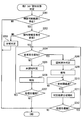
- S202 it is determined whether or not the recognition information reception processing unit F34 has received a recognition information signal from the target vehicle. If a recognition information signal is received from the target vehicle, S202 becomes YES and the process moves to S204. On the other hand, when the recognition information signal is not received from the target vehicle, S202 is NO and the process proceeds to S203.
- S202 is determined to be NO when a recognition information signal is not received from the target vehicle within a certain time.
- S204 based on the received recognition information signal, it is determined whether or not the driver of the target vehicle recognizes the host vehicle.
- the driver of the target vehicle recognizes the host vehicle, here, if the recognition flag included in the received recognition information signal is 1, S204 is YES and the process proceeds to S208. .
- S204 is NO and the process proceeds to S205.
- S205 it is determined that the recognition state of the other driver with respect to the vehicle is unrecognized, and the process proceeds to S206.
- the notification control unit F8 notifies the driver of information indicating that the driver of the target vehicle does not recognize the presence of the host vehicle, and proceeds to S207. More specifically, the notification control unit F8 displays an image or text indicating that the driver of the target vehicle does not recognize the presence of the host vehicle on the display device 6. Further, a sound indicating that the driver of the target vehicle does not recognize the presence of the host vehicle may be output from the sound output device 7.
- S207 it is determined whether or not to continue this flow.
- the case where it is determined that the present flow is continued is, for example, a case where the host vehicle is still in the visible range of the target vehicle. Moreover, the case where it determines with not continuing this flow is set as the case where the own vehicle leaves the visible range of a target vehicle.
- S207 is YES and the process proceeds to S204.
- S207 is NO and this flow is terminated. That is, it is determined that this flow is not continued, or S204 to S207 are repeated until a recognition information signal indicating that the driver of the target vehicle recognizes the host vehicle is received (YES in S204). Meanwhile, the determination that the recognition state of the other driver with respect to the own vehicle is unrecognized is maintained.
- the notification control unit F8 notifies the driver of information indicating that the driver of the target vehicle recognizes the presence of the host vehicle, and proceeds to S210. More specifically, the notification control unit F8 displays an image or text indicating that the driver of the target vehicle recognizes the presence of the host vehicle on the display device 6. In addition, a sound indicating that the driver of the target vehicle recognizes the presence of the host vehicle may be output from the sound output device 7.
- This determination result holding time is a time for holding the determination result that has been recognized, and may be appropriately designed. In this embodiment, 10 seconds is taken as an example, but it may be 5 seconds or 15 seconds.
- S210 is YES and the process proceeds to S211. On the other hand, while the determination result holding time has not elapsed, S210 is NO and S210 is repeated.
- S211 the determination result of the recognition state of the other driver with respect to the own vehicle is initialized, that is, the determination result that the vehicle is recognized is canceled, and the process proceeds to S212.
- S212 as in S207, it is determined whether or not to continue this flow. If it is determined in S212 that this flow is to be continued, S212 is YES and the process proceeds to S204. On the other hand, when it is determined in S212 that this flow is not continued, S212 is NO and this flow is terminated.
- This recognition information transmission related process is mainly performed by the self-driver recognition state determination unit F72 in cooperation with other functional blocks (recognition information transmission processing unit F33).
- recognition information transmission processing unit F33 the processing steps included in the recognition information transmission-related processing, regarding the processing steps performed by the own driver recognition state determination unit F72, description of the subject that performs the processing steps is omitted.
- the target vehicle referred to in the description of the flowchart shown in FIG. 7 refers to any one of the other vehicles set as the target vehicle in the surrounding vehicle list.
- the viewable range of the host vehicle may be calculated based on the position information of the host vehicle, the traveling direction, and the viewable range definition data registered in the memory 11.
- S301 is YES and the process moves to S302.
- S301 is NO and this flow is finished.
- the target vehicle if there is another vehicle between the target vehicle and the host vehicle, and the target vehicle cannot be detected by the other vehicle's surrounding monitoring system 3, the target vehicle Is determined not to be in the visible range of the host vehicle.
- the target vehicle is It is good also as a structure determined with existing in the visually recognizable range.
- a process of determining the recognition state of the driver for the target vehicle (referred to as a self-driver recognition state determination process) is performed, and the process proceeds to S303.
- the self-driver recognition state determination process performed in S302 will be described with reference to the flowchart shown in FIG.
- the flowchart shown in FIG. 8 is started when the process proceeds to S302 in FIG. 7 as described above. In addition, it implements sequentially as another aspect, You may hold
- the relative position of the target vehicle with respect to the host vehicle is acquired, and the direction in which the target vehicle exists (referred to as the target vehicle direction) is acquired.
- the line-of-sight direction of the own driver detected by the line-of-sight detection unit F6 is acquired.
- S33 it is determined whether or not the driver recognizes the target vehicle based on the driver's line-of-sight direction detected by the line-of-sight detection unit F6. For example, if the driver's line-of-sight direction acquired in S32 matches the target vehicle direction acquired in S31 for a certain time (referred to as a visual recognition determination time) or longer, the driver's target is the target. It is determined that the vehicle is recognized.
- the visual recognition determination time may be appropriately designed and is 1.5 seconds here.
- the driver's line-of-sight direction is the direction in which the door mirror corresponding to the side where the target vehicle exists is installed. It is determined that the driver has recognized the target vehicle when the running time is longer than the visual recognition time.
- the range in which the driver can see indirectly through the door mirror is based on, for example, the position of the driver's head detected by the driver monitor 5 and the angle of the door mirror detected by the drag mirror angle sensor. Just decide. Further, the position of the headrest of the driver's seat may be used instead of the position of the driver's head. The position of the headrest of the driver's seat may be determined based on an output value of a seat position sensor that detects the position of the driver's seat, or may be determined from a standard seat position.
- the periphery monitoring system 3 includes a camera (for example, a rear camera) that captures the periphery of the host vehicle, and displays an image including the target vehicle captured by the camera on the display device 6. If the driver's line-of-sight direction matches the direction in which the display device 6 is installed is equal to or longer than the visual recognition determination time, it is determined that the driver has recognized the target vehicle. Good.
- a camera for example, a rear camera
- S33 becomes YES and the process moves to S34.
- S33 is NO and the process proceeds to S35.
- S303 as a result of the self-driver recognition state determination process performed in S302, it is determined whether or not the recognition state of the self-driver with respect to the target vehicle is already recognized.
- S303 becomes YES and proceeds to S304.
- S303 is NO and the process proceeds to S308.
- the recognition information transmission processing unit F33 transmits a recognition information signal indicating that the driver recognizes the target vehicle toward the target vehicle. That is, a recognition information signal with a recognition flag set to 1 is transmitted to the target vehicle.
- the process in S304 proceeds to S305.
- S305 it is determined whether or not the determination result holding time has elapsed since the transmission of the recognition information signal. If the determination result holding time has elapsed since the transmission of the recognition information signal, S305 becomes YES and the process moves to S306. On the other hand, if the determination result holding time has not elapsed since the transmission of the recognition information signal, S305 is NO, and the process waits until the determination result holding time elapses by repeating S305. In S306, the recognition state of the driver for the target vehicle is returned to unrecognized (that is, initialized), and the process proceeds to S307.
- the case where it is determined that the present flow is continued is, for example, a case where the target vehicle is still in the visible range of the own vehicle. Moreover, the case where it determines with not continuing this flow is set as the case where a target vehicle leaves the visible range of the own vehicle.
- S307 If it is determined in S307 that this flow is to be continued, S307 becomes YES and the process proceeds to S302. On the other hand, when it is determined in S307 that this flow is not continued, S307 is NO and this flow is terminated.
- the recognition information transmission processing unit F33 transmits a recognition information signal indicating that the driver does not recognize the target vehicle toward the target vehicle. That is, a recognition information signal with the recognition flag set to 0 is transmitted to the target vehicle.
- the process in S308 proceeds to S309.
- a notification process for urging the driver to recognize the target vehicle is performed, and the process proceeds to S310. More specifically, the notification control unit F8 displays information on content that prompts the display device 6 to visually recognize the target vehicle direction. In addition, the notification control unit F8 may cause the audio output device 7 to output a sound that prompts the user to visually recognize the target vehicle direction. Furthermore, the driver of the host vehicle may be prompted to visually recognize the target vehicle direction by turning on an illumination device (not shown) provided on the door mirror on the side where the target vehicle exists.
- S310 as in S307, it is determined whether or not to continue this flow. If it is determined in S310 that this flow is to be continued, S310 becomes YES and the process moves to S302. On the other hand, when it is determined in S310 that this flow is not continued, S310 is NO and this flow is terminated.
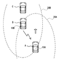
- FIG. 9 is a schematic diagram showing a situation where the vehicle A is about to overtake the vehicle B.
- the vehicle C is a preceding vehicle for the vehicle B. It is assumed that the lane in which the vehicle B travels is more crowded than the lane in which the vehicle A travels.
- Vehicles A and B are equipped with in-vehicle systems 10A and 10B, respectively.
- an alternate long and short dash line 20 ⁇ / b> A shown in FIG. 9 indicates the visible range of the vehicle A
- an alternate long and short dashed line 20 ⁇ / b> B indicates the visible range of the vehicle B. That is, FIG. 9 shows a time point when the vehicle A enters the visible range of the vehicle B and the vehicle B enters the visible range of the vehicle A.
- the vehicle A receives the recognition information signal from the vehicle B and the vehicle B transmits the recognition information signal to the vehicle A.
- the vehicle A is the own vehicle and the vehicle B is the other vehicle for the own vehicle A.
- the in-vehicle system 10A of the own vehicle A waits for the recognition information signal to be transmitted from the other vehicle B in response to the own vehicle A entering the visible range of the other vehicle B (S201 YES). (That is, it becomes a reception standby state). And if the recognition information signal from the other vehicle B is received (S202 YES), the other driver recognition state determination part F71 of the vehicle A will recognize the own vehicle A by the driver of the other vehicle B based on the recognition information signal. It is determined whether or not (S204).
- the driver of the vehicle B is the vehicle B A recognition information signal indicating that A is recognized is transmitted (S304). That is, the recognition information signal received by the vehicle A has a content indicating that the driver of the vehicle B recognizes the vehicle A (YES in S204). Then, the notification controller F8 of the vehicle A notifies the driver of the vehicle A that the driver of the vehicle B recognizes the vehicle A via the display device 6, the audio output device 7, and the like (S209).
- the driver of the own vehicle A can recognize that the driver of the other vehicle recognizes the own vehicle A.
- the driver recognition state determination unit F72 of the other vehicle B determines that the driver of the other vehicle B does not recognize the vehicle A (NO in S303)
- the driver of the vehicle B is the vehicle A A recognition information signal indicating that it is not recognized is transmitted (S308). That is, the recognition information signal received by the vehicle A has a content indicating that the driver of the vehicle B does not recognize the vehicle A (NO in S204).
- the notification control unit F8 of the vehicle A notifies the driver of the vehicle A that the driver of the vehicle B does not recognize the vehicle A via the display device 6, the audio output device 7, and the like (S206).
- the driver of the own vehicle A can recognize that the driver of the other vehicle does not recognize the own vehicle A.
- the vehicle B suddenly travels. You can make a prediction that the lane may change to the lane you are in.
- the other driver recognition state determination unit F71 of the vehicle A receives the recognition information signal from the vehicle B even after a certain time has elapsed after entering the visible range of the vehicle B. (S202: NO), it is determined whether or not the driver of the vehicle B recognizes the host vehicle (S203), and notifies the driver of the vehicle A to that effect.
- the driver of the own vehicle A can obtain information that it is unknown whether or not the driver of the other vehicle B recognizes the existence of the own vehicle A.
- the driver of the vehicle A is the same as when the driver of the vehicle B does not recognize the own vehicle A.
- a prediction that the lane may be changed to the traveling lane of the vehicle A can be made.
- the other driver recognition state determination unit F71 of the own vehicle A once determines that the driver of the other vehicle B has recognized the own vehicle A once, and the determination result holding time has elapsed. , Cancel the judgment result. And it was set as the structure which determines the recognition state with respect to the own vehicle A of the driver of the other vehicle B again. As a result, the state in which the host vehicle A and the other vehicle B are running in parallel continues for a determination result holding time or longer, and the driver of the other vehicle B is less aware of the host vehicle A. Can return to cognition.
- the in-vehicle system 10A of the own vehicle B receives the fact that the other vehicle A has entered the visible range of the own vehicle B (S301 YES), and the own driver recognition state determination unit F72 performs the own driver recognition state determination process. Then, it is determined whether or not the driver of the host vehicle B recognizes the other vehicle A (S302). When it is determined that the driver of the host vehicle B recognizes the other vehicle B (YES in S303), a recognition information signal indicating that the driver of the host vehicle B recognizes the other vehicle B is sent to the other vehicle B. Send.
- the notification control part F8 is with respect to the driver of the own vehicle B. Then, a notification that prompts the user to confirm the presence of the other vehicle A is performed. As a result, the driver of the host vehicle B can easily recognize the other vehicle A.
- the self-driver recognition state determination process is sequentially performed. Therefore, after that, when the driver of the own vehicle B recognizes the other vehicle A, a recognition information signal indicating that the driver of the own vehicle B recognizes the other vehicle A is transmitted to the other vehicle A.
- each vehicle A and vehicle B either one transmits the recognition information signal and the other receives the recognition information signal.
- each of vehicle A and vehicle B is the opponent. It is good also as a structure which transmits a recognition information signal toward. That is, the vehicle A may receive the recognition information signal from the vehicle B while transmitting the recognition information signal to the vehicle B.
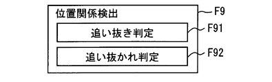
- the control unit 1 of Modification 1 includes a positional relationship change detection unit F9 in addition to the above-described functional blocks (F1 to F8).
- the positional relationship change detection unit F9 is configured to change the positional relationship between the host vehicle and the other vehicle based on the relative position between the host vehicle and the other vehicle traveling around the host vehicle and the temporal change in the relative position. At least one of the operations is detected.
- the change of the positional relationship here refers to changing the vehicle that becomes the preceding vehicle and the vehicle that becomes the succeeding vehicle.
- the time change of the relative position here may be represented by a relative speed.
- the relative velocity may be expressed by a relative acceleration determined by time differentiation.
- the positional relationship change detection unit F9 includes an overtaking determination unit F91 and an overtaking determination unit F92 as finer functional blocks.
- the process which the positional relationship change detection part F9 implements is implemented with respect to each of the other vehicles which drive
- the other vehicle traveling around the host vehicle may be the other vehicle detected by the periphery monitoring system 3 or may be another vehicle existing in the visible range of the host vehicle.
- the overtaking determination unit F91 determines whether or not the host vehicle is about to overtake another vehicle.
- the situation in which the host vehicle overtakes other vehicles is when the other vehicle traveling in front of the host vehicle is overtaken in the lane in which the host vehicle is traveling (referred to as the host vehicle lane), or adjacent to the host vehicle lane.
- a case may be considered in which the vehicle travels ahead of another vehicle in a lane (adjacent lane) in which the traveling direction is the same as the own vehicle lane.
- the overtaking determination unit F91 determines whether or not the own vehicle is about to overtake another vehicle traveling in the lane in front of the own vehicle in the adjacent lane.
- the other vehicle closest to the host vehicle is referred to as a front preceding vehicle
- Another vehicle close to the host vehicle is referred to as a side preceding vehicle.
- what is necessary is just to apply a well-known lane detection technique whether it is drive
- the overtaking determination unit F91 first determines whether the other vehicle is a side preceding vehicle from the relative position of the other vehicle with respect to the host vehicle. Next, when the other vehicle is a side preceding vehicle, it is determined whether or not the other vehicle can be overtaken while maintaining the traveling in the own vehicle traveling lane in the own vehicle traveling lane. To do. The case where the other vehicle can be overtaken while maintaining traveling in the own vehicle traveling lane is a case where there is no front leading vehicle in the own vehicle traveling lane at least to a region on the side of the other vehicle. . If it is determined that the other vehicle can be overtaken, it is determined whether or not the own vehicle is about to overtake the other vehicle from the time change of the relative position between the own vehicle and the other vehicle.
- the case where it is determined that the host vehicle is about to overtake the other vehicle is a case where the distance between the host vehicle and the other vehicle decreases with time, that is, the host vehicle This is the case when approaching another vehicle.
- the case where the own vehicle approaches the other vehicle means a case where the relative speed of the other vehicle with respect to the own vehicle is negative. Therefore, when the relative speed of the other vehicle with respect to the own vehicle is negative, it may be determined that the own vehicle is about to overtake the other vehicle. Furthermore, when the relative speed of the other vehicle with respect to the own vehicle is negative, it may be determined that the own vehicle is about to pass the other vehicle.
- the overtaking determination unit F91 determines whether or not the host vehicle is about to overtake the side preceding vehicle. Then, based on the fact that the overtaking determination unit F91 has determined that the own vehicle is about to overtake the side preceding vehicle, the other driver recognition state determination unit F71 targets the other vehicle that the own vehicle is about to overtake The other driver recognition state determination process is started. Further, when it is determined by the overtaking determination unit F91 that the own vehicle is about to overtake the side preceding vehicle, the control unit 1 transmits cognitive information for another vehicle that the own vehicle is about to overtake. Related processing shall not be implemented. Accordingly, the own driver recognition state determination unit F72 does not perform the own driver recognition state determination process for the other vehicle.
- the overtaking determination unit F91 determines whether or not the own vehicle is about to overtake another vehicle corresponding to the side preceding vehicle has been described, but the other vehicle corresponding to the front preceding vehicle is described.
- a condition for determining that it is overtaking another vehicle may be designed as appropriate.
- the same determination condition as the above-described process can be applied to the process of determining whether or not to overtake the front preceding vehicle.
- the overtake determination unit F92 determines whether or not the own vehicle is about to be overtaken by another vehicle, that is, whether or not the other vehicle is overtaking the own vehicle.
- the situation where the host vehicle is overtaken by another vehicle may be the case where the host vehicle is overtaken by another vehicle traveling behind the host vehicle in the own vehicle lane or the case where the host vehicle is overtaken by another vehicle traveling in the adjacent lane. It is done.
- the overtaken determination unit F92 determines whether or not another vehicle traveling in the adjacent lane is overtaken.
- the other vehicle closest to the host vehicle is referred to as a rear succeeding vehicle
- Other vehicles close to the host vehicle are referred to as side succeeding vehicles.
- the overtaking determination unit F92 first determines whether or not the other vehicle is a side succeeding vehicle from the relative position of the other vehicle with respect to the host vehicle. When the other vehicle is a side preceding vehicle, it is determined whether or not the other vehicle can pass the own vehicle.
- the case where the other vehicle can overtake the host vehicle means that another other vehicle is located between the area corresponding to the side of the host vehicle and the area corresponding to the front side of the host vehicle in the lane in which the side succeeding vehicle travels. For example, it does not exist. If it is determined that the other vehicle can overtake the host vehicle, it is determined whether or not the host vehicle is about to pass the other vehicle based on a temporal change in the relative position between the host vehicle and the other vehicle. To do.
- the case where it is determined that the other vehicle is about to overtake the host vehicle is a case where the distance between the host vehicle and the other vehicle is decreasing with time, that is, the other vehicle is This is the case when the vehicle is approaching.
- the case where another vehicle approaches the own vehicle means the case where the relative speed of the other vehicle with respect to the own vehicle is positive.
- the relative speed of the other vehicle with respect to the own vehicle is positive, it may be determined that the other vehicle is about to overtake the own vehicle.
- the overtaking determination unit F92 determines whether or not the side succeeding vehicle is about to overtake the own vehicle, that is, whether or not the own vehicle is about to be overtaken by the rear following vehicle. Then, based on the fact that the overtaking determination unit F92 determines that the own vehicle is about to be overtaken by the side preceding vehicle, the own driver recognition state determination unit F72 detects other vehicles that are overtaking the own vehicle. The target driver recognition state determination process is started.
- the overtaking determination unit F92 determines that the host vehicle is about to be overtaken by the side preceding vehicle, the other driver recognition state determination for another vehicle trying to overtake the host vehicle is performed. It is set as the structure which does not implement a process.
- the process when the overtaken determination unit F92 determines whether or not another vehicle corresponding to the side succeeding vehicle is about to overtake the own vehicle has been described.
- a condition for determining that the vehicle is about to overtake another vehicle may be designed as appropriate.
- the vehicle that is to transmit the recognition information signal for example, in a combination of the own vehicle and the other vehicle whose positional relationship is to be changed, such as the preceding vehicle and the following vehicle, the vehicle that is to transmit the recognition information signal, and the recognition It is possible to distinguish the vehicle that is to receive the information signal.
- the host vehicle when the host vehicle is trying to overtake another vehicle corresponding to the side preceding vehicle, as described in the embodiment, information such as whether or not the driver of the other vehicle recognizes the host vehicle is It can be said that it is useful for the driver. However, it is highly likely that it is not useful for the driver of the other vehicle corresponding to the side preceding vehicle whether or not the driver of the host vehicle recognizes the side preceding vehicle.
- the overtaking vehicle (referred to as an overtaking vehicle) is a self-driver for the vehicle that the vehicle is to overtake (referred to as the overtaken vehicle).
- the recognition state determination process is not performed, and the recognition information signal is not transmitted to the vehicle to be overtaken.
- the control unit 1 of the overtaken vehicle does not perform the other driver recognition state determination process for the overtaken vehicle. For this reason, it can prevent that the recognition state of the driver of the overtake vehicle with respect to the overtaken vehicle is notified to the driver of the overtaken vehicle. That is, it is possible to prevent notification of low useful information to the driver of the vehicle to be overtaken.
- the positional relationship change detection unit F9 detects an operation in which the own vehicle tries to overtake another vehicle and an operation in which the other vehicle tries to overtake the own vehicle has been described.
- the operation by the own vehicle or another vehicle that attempts to change the positional relationship detected by the positional relationship change detection unit F9 is not limited thereto.
- the operation of the own vehicle or other vehicle to change the lane the operation of the own vehicle trying to interrupt between a plurality of other vehicles in the relationship between the front preceding vehicle and the rear succeeding vehicle,
- the movement of another vehicle that is about to interrupt the front vehicle of the host vehicle may be detected.
- These movements may be determined, for example, based on whether the direction indicating lever position of the host vehicle or the other vehicle is the right turn position or the left turn position. What is necessary is just to acquire the position of the direction indication lever of the own vehicle from the direction indication lever position sensor with which the vehicle-mounted sensor group 4 is provided. Moreover, what is necessary is just to acquire the position of the direction indication lever of another vehicle from vehicle information, when it is contained in vehicle information. Then, when the direction indicating lever is at the right turn position or the left turn position, it may be determined that the vehicle is about to change lanes.
- the lane is changed when the host vehicle or another vehicle approaches the white line or detects an operation that exceeds the white line. What is necessary is just to determine that it exists.
- the vehicle whose lane is to be changed is another vehicle, it may be determined whether or not an interruption is to be made based on the positional relationship between the other vehicle, the host vehicle, and other surrounding vehicles. For example, when a side preceding vehicle existing between the front preceding vehicle and the host vehicle is about to change lanes in the traveling direction, it may be determined that an interruption is about to be made.
- Modification 2 In the above-described embodiment and Modification 1, although the driver of the own vehicle transmits a recognition information signal indicating the fact to the other vehicle even when the driver does not recognize the other vehicle, the present invention is not limited thereto.
- a signal indicating that is sent to the other vehicle referred to as a recognized signal
- the driver of the own vehicle does not recognize the other vehicle
- it may be configured not to transmit a signal indicating that.
- This recognized signal corresponds to the signal of the present disclosure.
- the other vehicle transmits a recognized signal toward the own vehicle only when the driver of the other vehicle recognizes the own vehicle.
- the in-vehicle system 10 of the own vehicle When the in-vehicle system 10 of the own vehicle receives a recognized signal from another vehicle, the in-vehicle system 10 notifies the driver of the own vehicle that the driver of the other vehicle recognizes the own vehicle. Even in such a configuration, the driver of the host vehicle can recognize that the driver of the other vehicle recognizes the host vehicle.
- the communication between the host vehicle and the target vehicle is performed by inter-vehicle communication.
- the present invention is not limited to this. Communication between the host vehicle and the other vehicle may be performed via a server or the like provided outside the vehicle.
- the recognition state of the other driver's own vehicle is classified into three recognized states: recognized, unrecognized, and unknown.
- recognized unrecognized
- unknown unrecognized
- the present invention is not limited to this. Unrecognized and unknown may be combined, and only recognized and unknown.
- the self-driver recognition state determination process is performed in S302 of the recognition information transmission-related process in FIG. 7, but the present invention is not limited thereto.
- the own driver recognition state determination unit F72 sequentially executes the own driver recognition state determination process independently of the recognition information transmission related process, and the determination result is stored in association with the vehicle ID of the surrounding vehicle list. You should do it.
- the recognition state of the driver already determined at that time may be acquired and the determination in S303 may be performed.
- the other driver recognition state determination process is performed based on whether or not the host vehicle enters the viewable range of the target vehicle.
- the present invention is not limited to this.
- the above-described recognition information request signal may be automatically transmitted based on the positional relationship between the other vehicle and the host vehicle, or transmitted based on the driver of the host vehicle operating the input device 8. May be.
- each step is expressed as S101, for example. Further, each step can be divided into a plurality of sub-steps, while a plurality of steps can be combined into one step.
Landscapes
- Physics & Mathematics (AREA)
- General Physics & Mathematics (AREA)
- Engineering & Computer Science (AREA)
- Radar, Positioning & Navigation (AREA)
- Remote Sensing (AREA)
- Traffic Control Systems (AREA)
Priority Applications (3)
| Application Number | Priority Date | Filing Date | Title |
|---|---|---|---|
| DE112015001534.5T DE112015001534B4 (de) | 2014-03-28 | 2015-03-16 | Fahrzeugerkennungsbenachrichtigungsvorrichtung und Fahrzeugerkennungsbenachrichtigungssystem |
| CN201580017189.8A CN106415693B (zh) | 2014-03-28 | 2015-03-16 | 车辆用认知通知装置、车辆用认知通知系统 |
| US15/126,088 US9747800B2 (en) | 2014-03-28 | 2015-03-16 | Vehicle recognition notification apparatus and vehicle recognition notification system |
Applications Claiming Priority (2)
| Application Number | Priority Date | Filing Date | Title |
|---|---|---|---|
| JP2014070022A JP6252304B2 (ja) | 2014-03-28 | 2014-03-28 | 車両用認知通知装置、車両用認知通知システム |
| JP2014-070022 | 2014-03-28 |
Publications (1)
| Publication Number | Publication Date |
|---|---|
| WO2015146061A1 true WO2015146061A1 (ja) | 2015-10-01 |
Family
ID=54194612
Family Applications (1)
| Application Number | Title | Priority Date | Filing Date |
|---|---|---|---|
| PCT/JP2015/001446 Ceased WO2015146061A1 (ja) | 2014-03-28 | 2015-03-16 | 車両用認知通知装置、車両用認知通知システム |
Country Status (5)
| Country | Link |
|---|---|
| US (1) | US9747800B2 (enExample) |
| JP (1) | JP6252304B2 (enExample) |
| CN (1) | CN106415693B (enExample) |
| DE (1) | DE112015001534B4 (enExample) |
| WO (1) | WO2015146061A1 (enExample) |
Cited By (1)
| Publication number | Priority date | Publication date | Assignee | Title |
|---|---|---|---|---|
| JP2019197526A (ja) * | 2018-03-14 | 2019-11-14 | ホンダ リサーチ インスティテュート ヨーロッパ ゲーエムベーハーHonda Research Institute Europe GmbH | 自車両の操作を支援するための方法、他の交通参加者を支援するための方法、ならびに対応する支援システムおよび車両 |
Families Citing this family (34)
| Publication number | Priority date | Publication date | Assignee | Title |
|---|---|---|---|---|
| JP6252304B2 (ja) | 2014-03-28 | 2017-12-27 | 株式会社デンソー | 車両用認知通知装置、車両用認知通知システム |
| US9959765B2 (en) * | 2015-07-20 | 2018-05-01 | Dura Operating Llc | System and method for providing alert to a vehicle or an advanced driver assist system based on vehicle dynamics input |
| WO2017104224A1 (ja) * | 2015-12-15 | 2017-06-22 | 株式会社村田製作所 | 運転支援情報伝送システム、送信機、受信機、運転支援システム、及び運転支援情報伝送方法 |
| US20170327037A1 (en) * | 2016-05-10 | 2017-11-16 | Ford Global Technologies, Llc | Adaptive rear view display |
| JP2017212579A (ja) * | 2016-05-25 | 2017-11-30 | 住友電気工業株式会社 | 通信機および移動通信機 |
| JP6765100B2 (ja) | 2016-08-31 | 2020-10-07 | 学校法人早稲田大学 | 視野外障害物検知システム |
| CN108501949B (zh) * | 2017-02-27 | 2022-11-22 | 松下电器(美国)知识产权公司 | 信息处理装置以及记录介质 |
| JP6515125B2 (ja) * | 2017-03-10 | 2019-05-15 | 株式会社Subaru | 画像表示装置 |
| JP6722132B2 (ja) * | 2017-04-27 | 2020-07-15 | クラリオン株式会社 | 推奨運転出力装置、推奨運転出力方法、及び推奨運転出力システム |
| DE112017007515T5 (de) * | 2017-05-09 | 2020-10-15 | Mitsubishi Electric Corporation | Fahrzeuginternes Authentifikationssystem, fahrzeuginternes Authentifikationsverfahren und fahrzeuginternes Authentifikationsprogramm |
| US10534092B2 (en) * | 2017-06-01 | 2020-01-14 | Tesla, Inc. | Technologies for vehicle positioning |
| JP7162233B2 (ja) * | 2017-06-08 | 2022-10-28 | 学校法人早稲田大学 | 障害物探知システム |
| JP6984281B2 (ja) * | 2017-09-27 | 2021-12-17 | トヨタ自動車株式会社 | 車両状態提示システム、車両、端末装置、および、方法 |
| JP6894354B2 (ja) * | 2017-11-24 | 2021-06-30 | 本田技研工業株式会社 | 車両制御装置、車両制御方法、およびプログラム |
| JP2019125039A (ja) * | 2018-01-12 | 2019-07-25 | トヨタ自動車株式会社 | 判定装置、判定方法及びプログラム |
| US10623834B1 (en) * | 2018-01-15 | 2020-04-14 | United Services Automobile Association (Usaa) | Vehicle tracking techniques |
| JP7003689B2 (ja) * | 2018-01-29 | 2022-01-20 | トヨタ自動車株式会社 | 制御装置およびエージェント連携方法 |
| JP2019159638A (ja) * | 2018-03-12 | 2019-09-19 | 矢崎総業株式会社 | 車載システム |
| JP6823003B2 (ja) | 2018-03-29 | 2021-01-27 | 本田技研工業株式会社 | 出力装置 |
| US11611878B2 (en) | 2018-04-16 | 2023-03-21 | Mitsubishi Electric Corporation | Vehicle communication device |
| CN109448409A (zh) * | 2018-10-30 | 2019-03-08 | 百度在线网络技术(北京)有限公司 | 交通信息交互的方法、装置、设备和计算机存储介质 |
| JP7053438B2 (ja) * | 2018-11-26 | 2022-04-12 | 株式会社東芝 | 電子装置、電子システム、方法、およびプログラム |
| JP7234614B2 (ja) | 2018-12-10 | 2023-03-08 | トヨタ自動車株式会社 | 異常検出装置、異常検出システム及び異常検出プログラム |
| JP7095591B2 (ja) * | 2018-12-28 | 2022-07-05 | トヨタ自動車株式会社 | 報知装置及び車両制御装置 |
| CN113454692B9 (zh) * | 2019-02-19 | 2024-07-02 | Sk电信有限公司 | 驾驶信息提供方法以及车辆地图提供服务器和方法 |
| KR102733277B1 (ko) * | 2019-02-21 | 2024-11-21 | 현대자동차주식회사 | 저비용 자율 주행 셔틀 운행 방법 및 장치 |
| JP7197416B2 (ja) * | 2019-03-28 | 2022-12-27 | 株式会社デンソーテン | 制御装置、及び、制御部の動作方法 |
| CN112153567A (zh) * | 2019-06-28 | 2020-12-29 | 大陆泰密克汽车系统(上海)有限公司 | 用于构建实时区域电子地图的方法和车辆 |
| CN110356344A (zh) * | 2019-07-24 | 2019-10-22 | 重庆长安汽车股份有限公司 | 一种应用于全景系统的车载事件记录方法、系统及汽车 |
| JP7532053B2 (ja) * | 2020-03-19 | 2024-08-13 | 日産自動車株式会社 | 対象物提示装置及び対象物提示方法 |
| CN113361460A (zh) * | 2021-06-29 | 2021-09-07 | 广州小鹏汽车科技有限公司 | 图像显示的控制方法、控制装置、电子设备、车辆和介质 |
| US11651692B2 (en) * | 2021-10-07 | 2023-05-16 | Qualcomm Incorporated | Presenting relevant warnings to a vehicle operator |
| KR20240146225A (ko) * | 2023-03-29 | 2024-10-08 | 주식회사 에이치엘클레무브 | 차량 및 그 제어 방법 |
| US12472984B2 (en) * | 2023-09-26 | 2025-11-18 | Honda Motor Co., Ltd. | Method, program, storage medium and assistance system for assisting ego-agent and vehicle |
Citations (5)
| Publication number | Priority date | Publication date | Assignee | Title |
|---|---|---|---|---|
| JP2007249757A (ja) * | 2006-03-17 | 2007-09-27 | Denso It Laboratory Inc | 警報装置 |
| JP2008210051A (ja) * | 2007-02-23 | 2008-09-11 | Mazda Motor Corp | 車両用運転支援システム |
| JP2009134704A (ja) * | 2007-11-05 | 2009-06-18 | Fujitsu Ten Ltd | 周辺監視装置、安全走行支援システム、及び車両 |
| JP2010238053A (ja) * | 2009-03-31 | 2010-10-21 | Hino Motors Ltd | 並走警報装置、車両およびプログラム |
| JP2013206183A (ja) * | 2012-03-28 | 2013-10-07 | Fujitsu Ltd | 事故予防装置、事故予防方法およびプログラム |
Family Cites Families (15)
| Publication number | Priority date | Publication date | Assignee | Title |
|---|---|---|---|---|
| JP3884815B2 (ja) * | 1997-03-03 | 2007-02-21 | 本田技研工業株式会社 | 車両用情報表示装置 |
| JP3773040B2 (ja) | 2001-10-31 | 2006-05-10 | 本田技研工業株式会社 | 車両用認知支援システム |
| US20050128063A1 (en) | 2003-11-28 | 2005-06-16 | Denso Corporation | Vehicle driving assisting apparatus |
| JP4645891B2 (ja) | 2005-03-24 | 2011-03-09 | 日本精機株式会社 | 車両用運転支援装置及び車両用運転支援方法 |
| JP4797588B2 (ja) * | 2005-11-17 | 2011-10-19 | アイシン精機株式会社 | 車両周辺表示装置 |
| WO2008029802A1 (en) * | 2006-09-04 | 2008-03-13 | Panasonic Corporation | Travel information providing device |
| JP5050735B2 (ja) * | 2007-08-27 | 2012-10-17 | マツダ株式会社 | 車両用運転支援装置 |
| WO2009060581A1 (ja) * | 2007-11-05 | 2009-05-14 | Fujitsu Ten Limited | 周辺監視装置、安全走行支援システム、及び車両 |
| JP2010287162A (ja) * | 2009-06-15 | 2010-12-24 | Aisin Aw Co Ltd | 運転支援装置及びプログラム |
| JP5353999B2 (ja) * | 2011-04-01 | 2013-11-27 | 株式会社デンソー | 運転者支援装置 |
| CN103582906B (zh) * | 2011-06-02 | 2016-01-20 | 丰田自动车株式会社 | 车辆用视野辅助装置 |
| EP2736028B1 (en) * | 2011-07-21 | 2019-05-22 | Toyota Jidosha Kabushiki Kaisha | Vehicle information transmitting apparatus |
| CN103917410B (zh) * | 2011-08-11 | 2016-12-07 | 福特全球技术公司 | 建立声学指标以检测驾驶员头脑糊涂的系统和方法 |
| JP5965803B2 (ja) | 2012-09-27 | 2016-08-10 | 株式会社マンダム | デオドラント組成物及びデオドラント剤 |
| JP6252304B2 (ja) | 2014-03-28 | 2017-12-27 | 株式会社デンソー | 車両用認知通知装置、車両用認知通知システム |
-
2014
- 2014-03-28 JP JP2014070022A patent/JP6252304B2/ja not_active Expired - Fee Related
-
2015
- 2015-03-16 DE DE112015001534.5T patent/DE112015001534B4/de not_active Expired - Fee Related
- 2015-03-16 WO PCT/JP2015/001446 patent/WO2015146061A1/ja not_active Ceased
- 2015-03-16 US US15/126,088 patent/US9747800B2/en not_active Expired - Fee Related
- 2015-03-16 CN CN201580017189.8A patent/CN106415693B/zh not_active Expired - Fee Related
Patent Citations (5)
| Publication number | Priority date | Publication date | Assignee | Title |
|---|---|---|---|---|
| JP2007249757A (ja) * | 2006-03-17 | 2007-09-27 | Denso It Laboratory Inc | 警報装置 |
| JP2008210051A (ja) * | 2007-02-23 | 2008-09-11 | Mazda Motor Corp | 車両用運転支援システム |
| JP2009134704A (ja) * | 2007-11-05 | 2009-06-18 | Fujitsu Ten Ltd | 周辺監視装置、安全走行支援システム、及び車両 |
| JP2010238053A (ja) * | 2009-03-31 | 2010-10-21 | Hino Motors Ltd | 並走警報装置、車両およびプログラム |
| JP2013206183A (ja) * | 2012-03-28 | 2013-10-07 | Fujitsu Ltd | 事故予防装置、事故予防方法およびプログラム |
Cited By (1)
| Publication number | Priority date | Publication date | Assignee | Title |
|---|---|---|---|---|
| JP2019197526A (ja) * | 2018-03-14 | 2019-11-14 | ホンダ リサーチ インスティテュート ヨーロッパ ゲーエムベーハーHonda Research Institute Europe GmbH | 自車両の操作を支援するための方法、他の交通参加者を支援するための方法、ならびに対応する支援システムおよび車両 |
Also Published As
| Publication number | Publication date |
|---|---|
| CN106415693A (zh) | 2017-02-15 |
| DE112015001534T5 (de) | 2016-12-15 |
| DE112015001534B4 (de) | 2021-11-04 |
| CN106415693B (zh) | 2019-01-11 |
| JP6252304B2 (ja) | 2017-12-27 |
| JP2015191583A (ja) | 2015-11-02 |
| US9747800B2 (en) | 2017-08-29 |
| US20170076605A1 (en) | 2017-03-16 |
Similar Documents
| Publication | Publication Date | Title |
|---|---|---|
| JP6252304B2 (ja) | 車両用認知通知装置、車両用認知通知システム | |
| US12183205B2 (en) | Obstacle information management device, obstacle information management method, and device for vehicle | |
| JP7043450B2 (ja) | 車両制御装置、車両制御方法、及びプログラム | |
| JP7310524B2 (ja) | 遠隔自動運転車両、及び車両遠隔指示システム | |
| JP6976280B2 (ja) | 車両制御装置、車両制御方法、及びプログラム | |
| JP6354776B2 (ja) | 車両の制御装置 | |
| CN105799700B (zh) | 避免碰撞控制系统和控制方法 | |
| US20190315348A1 (en) | Vehicle control device, vehicle control method, and storage medium | |
| KR20210083462A (ko) | 운전자 보조 시스템, 그를 가지는 차량 및 그 제어 방법 | |
| US10262629B2 (en) | Display device | |
| US20190071071A1 (en) | Vehicle control device, vehicle control method, and storage medium | |
| JP6827378B2 (ja) | 車両制御システム、車両制御方法、およびプログラム | |
| US20190071075A1 (en) | Vehicle control system, vehicle control method, and vehicle control program | |
| CN111762166A (zh) | 车辆控制装置、车辆控制方法及存储介质 | |
| JP7047824B2 (ja) | 車両制御装置 | |
| KR102718382B1 (ko) | 정보 처리 장치 및 정보 처리 방법, 컴퓨터 프로그램, 그리고 이동체 장치 | |
| CN112534297B (zh) | 信息处理设备和信息处理方法、计算机程序、信息处理系统以及移动设备 | |
| JPWO2018122966A1 (ja) | 車両制御システム、車両制御方法、および車両制御プログラム | |
| KR20180072139A (ko) | 차량 및 그 제어 방법 | |
| KR102611337B1 (ko) | 차량의 ar 디스플레이 장치 및 그것의 동작방법 | |
| JP7348942B2 (ja) | 車両制御装置、車両制御方法、およびプログラム | |
| US12221103B2 (en) | Vehicle control device, vehicle control method, and storage medium | |
| US10640128B2 (en) | Vehicle control device, vehicle control method, and storage medium | |
| WO2017104209A1 (ja) | 運転支援装置 | |
| JP2015093568A (ja) | 車載装置 |
Legal Events
| Date | Code | Title | Description |
|---|---|---|---|
| 121 | Ep: the epo has been informed by wipo that ep was designated in this application |
Ref document number: 15768590 Country of ref document: EP Kind code of ref document: A1 |
|
| WWE | Wipo information: entry into national phase |
Ref document number: 15126088 Country of ref document: US |
|
| WWE | Wipo information: entry into national phase |
Ref document number: 112015001534 Country of ref document: DE |
|
| 122 | Ep: pct application non-entry in european phase |
Ref document number: 15768590 Country of ref document: EP Kind code of ref document: A1 |