WO2015141587A1 - メタルガスケット - Google Patents
メタルガスケット Download PDFInfo
- Publication number
- WO2015141587A1 WO2015141587A1 PCT/JP2015/057513 JP2015057513W WO2015141587A1 WO 2015141587 A1 WO2015141587 A1 WO 2015141587A1 JP 2015057513 W JP2015057513 W JP 2015057513W WO 2015141587 A1 WO2015141587 A1 WO 2015141587A1
- Authority
- WO
- WIPO (PCT)
- Prior art keywords
- full bead
- elastic coating
- metal gasket
- concave surface
- gasket
- Prior art date
- Legal status (The legal status is an assumption and is not a legal conclusion. Google has not performed a legal analysis and makes no representation as to the accuracy of the status listed.)
- Ceased
Links
Images



Classifications
-
- F—MECHANICAL ENGINEERING; LIGHTING; HEATING; WEAPONS; BLASTING
- F16—ENGINEERING ELEMENTS AND UNITS; GENERAL MEASURES FOR PRODUCING AND MAINTAINING EFFECTIVE FUNCTIONING OF MACHINES OR INSTALLATIONS; THERMAL INSULATION IN GENERAL
- F16J—PISTONS; CYLINDERS; SEALINGS
- F16J15/00—Sealings
- F16J15/02—Sealings between relatively-stationary surfaces
- F16J15/06—Sealings between relatively-stationary surfaces with solid packing compressed between sealing surfaces
- F16J15/08—Sealings between relatively-stationary surfaces with solid packing compressed between sealing surfaces with exclusively metal packing
- F16J15/0818—Flat gaskets
-
- F—MECHANICAL ENGINEERING; LIGHTING; HEATING; WEAPONS; BLASTING
- F16—ENGINEERING ELEMENTS AND UNITS; GENERAL MEASURES FOR PRODUCING AND MAINTAINING EFFECTIVE FUNCTIONING OF MACHINES OR INSTALLATIONS; THERMAL INSULATION IN GENERAL
- F16J—PISTONS; CYLINDERS; SEALINGS
- F16J15/00—Sealings
- F16J15/02—Sealings between relatively-stationary surfaces
- F16J15/06—Sealings between relatively-stationary surfaces with solid packing compressed between sealing surfaces
- F16J15/08—Sealings between relatively-stationary surfaces with solid packing compressed between sealing surfaces with exclusively metal packing
- F16J15/0818—Flat gaskets
- F16J2015/085—Flat gaskets without fold over
-
- F—MECHANICAL ENGINEERING; LIGHTING; HEATING; WEAPONS; BLASTING
- F16—ENGINEERING ELEMENTS AND UNITS; GENERAL MEASURES FOR PRODUCING AND MAINTAINING EFFECTIVE FUNCTIONING OF MACHINES OR INSTALLATIONS; THERMAL INSULATION IN GENERAL
- F16J—PISTONS; CYLINDERS; SEALINGS
- F16J15/00—Sealings
- F16J15/02—Sealings between relatively-stationary surfaces
- F16J15/06—Sealings between relatively-stationary surfaces with solid packing compressed between sealing surfaces
- F16J15/08—Sealings between relatively-stationary surfaces with solid packing compressed between sealing surfaces with exclusively metal packing
- F16J15/0818—Flat gaskets
- F16J2015/0856—Flat gaskets with a non-metallic coating or strip
Definitions
- the present invention relates to a metal gasket, and more particularly, to a metal gasket in which an elastic coating is formed on a metal substrate that is interposed between opposing surfaces of two mating members in a compressed state, and in particular, a full bead having spring properties.
- the metal gasket is fastened with bolts while being sandwiched between the opposing surfaces of the two mating members, and seals the space to be sealed defined by the two mating members.
- the substrate constituting the metal gasket has a full bead bent to form a convex surface on one side in the thickness direction. There is.
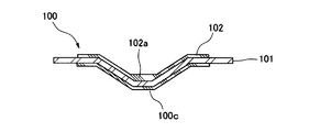
- FIG. 6 is a cross-sectional view showing a state where a full bead portion of a conventional metal gasket is cut along the width direction of the full bead.
- a full bead 100c of this type of metal gasket 100 has a chevron-shaped convex surface on one side in the thickness direction of the substrate 101 (lower side in FIG. 6) and a valley-shaped concave surface on the other side in the thickness direction (upper side in FIG. 6). It is bent to form.
- the metal gasket 100 When the metal gasket 100 is made of only a single metal substrate, it may not be able to follow the surface roughness of the opposing surface of the mating member, and a sufficient sealing function may not be obtained. For this reason, it is a common practice to coat (after-coat) an elastic film 102 made of a rubber-like elastic material so as to cover the full bead 100c on both surfaces of the metal substrate 101 on which the full bead 100c is formed. (Patent Document 1).
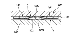
- the metal gasket 100 has a thick coating reservoir 102a at the bottom because the coating material accumulates at the bottom of the concave side of the full bead 100c when the elastic coating 102 is aftercoated on the substrate 101. Is easily formed. Therefore, as shown in FIG. 7, when the metal gasket 100 is mounted between two mating members 200 and 300 and tightened, the coating reservoir 102a thicker than the elastic coating 102 obstructs the full bead 100c. The amount of compression will be insufficient. As a result, a gap ⁇ is formed between the mating members 200 and 300, and there is a possibility that sufficient sealing performance cannot be obtained.
- the present invention has been made in view of the above points, and even if an elastic coating is formed along the full bead, the full bead can be sufficiently compressed to improve the sealing performance. Let it be an issue.
- a full bead having a chevron-shaped convex surface on one side in the thickness direction and a valley-shaped concave surface on the other side in the thickness direction is formed on a metal substrate
- An elastic coating is formed on the entire convex surface of the full bead
- a metal gasket characterized in that an elastic coating is formed on the concave surface of the full bead, leaving a slit-like elastic coating non-applied portion along the bottom of the concave surface.
- the full bead can be sufficiently compressed and the sealing performance can be improved.
- the disassembled perspective view which shows the assembly
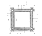
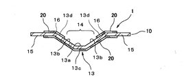
- Bottom view of the metal gasket shown in FIG. Enlarged cross-sectional view along line (iii)-(iii) in FIG.
- Sectional drawing which shows the mounting state of the metal gasket shown in FIG.
- Partial top view which shows an example of the cylinder head gasket used in order to seal between the cylinder head and cylinder block of the internal combustion engine of a motor vehicle
- Sectional drawing which shows the state which cut
- Sectional drawing which shows the mounting state of the conventional metal gasket shown in FIG.
- FIG. 1 is an exploded perspective view showing an assembled state of a metal gasket according to the present invention
- FIG. 2 is a bottom view of the metal gasket shown in FIG. 1
- FIG. 3 is a line (iii)-(iii) in FIG. FIG.
- the metal gasket 1 according to the present invention is disposed between opposing surfaces of two mating members 2 and 3 that define a sealed space S and is fastened together by bolts 4.
- the metal gasket 1 has, for example, a metal substrate 10 such as stainless steel, a cold-rolled steel plate, a galvanized steel plate, and an aluminum plywood, and an opening 11 corresponding to the space S to be sealed and a bolt hole 12 are formed.
- a metal substrate 10 such as stainless steel, a cold-rolled steel plate, a galvanized steel plate, and an aluminum plywood, and an opening 11 corresponding to the space S to be sealed and a bolt hole 12 are formed.
- a full bead 13 having a spring property is formed between adjacent bolt holes 12, 12.
- the full bead 13 has an angled convex surface on one side in the thickness direction (lower side in FIG. 3) and a bolt-shaped concave surface on the other side in the thickness direction (upper side in FIG. 3). It is formed by bending the substrate 10.
- the substrate 10 is coated with an elastic film 20 made of a rubber-like elastic material (rubber material or synthetic resin material having rubber-like elasticity) along the full bead 13. After-coating).
- an elastic film 20 made of a rubber-like elastic material (rubber material or synthetic resin material having rubber-like elasticity) along the full bead 13. After-coating).
- the elastic coating 20 is formed on the entire convex surface of the full bead 13. Further, on the concave surface of the full bead 13, a slit-like elastic coating non-application portion 14 is provided in a portion along the bottom portion 13a of the concave surface, specifically, in a region extending from the bottom portion 13a to the intermediate portions of the slopes 13b and 13b on both sides thereof.
- the elastic film 20 is formed to remain.
- the elastic coating 20 is applied to the entire convex surface side of the full bead 13 from a part of the flat plate portions 15 on both sides in the width direction to the top portion 13c of the full bead 13.
- the region from the bottom portion 13a to the middle portion of the slopes 13b, 13b on both sides thereof is the elastic coating non-application portion 14, and the elastic coating 20 is not formed.
- the elastic coating 20 is applied only to a region from the intermediate portion to a portion of the flat plate portions 15 on both sides thereof.
- the concave side elastic coating 20 of the full bead 13 is formed from both hem portions 13 d and 13 d of the full bead 13 to the flat plate portion 15 of the substrate 10. For this reason, the bent portions 16 and 16 which are the boundary portions between the hem portions 13 d and 13 d of the full bead 13 and the flat plate portions 15 and 15 are covered with the elastic coating 20.
- FIG. 4 is a cross-sectional view showing a mounted state of the metal gasket 1 shown in FIG.
- This metal gasket 1 is mounted between the opposing surfaces of the mating members 2 and 3 and tightened, whereby the full bead 13 is compressed and deformed. At this time, due to the compression reaction force of the full bead 13, the elastic coating 20 on the top portion 13 c of the full bead 13 comes into close contact with the opposing surface of the mating member 3 with an appropriate surface pressure. At this time, since the elastic coating 20 completely fills the surface roughness of the opposing surface of the counterpart member 3, the metal gasket 1 exhibits an excellent sealing function in combination with the surface pressure exhibited by the full bead 13.
- the bottom portion 13a of the concave surface of the full bead 13 in the unmounted state of FIG. 3 is an elastic coating non-application portion 14 in which the elastic coating 20 is not formed, and the bottom portion 13a has a conventional coating reservoir. do not do. Therefore, in the tightened state shown in FIG. 4, the full bead 13 can be almost completely compressed and deformed into a flat shape. As a result, it is possible to prevent a gap due to insufficient compression between the elastic coating 20 and the mating members 2 and 3 and to obtain a sufficient seal surface pressure. Therefore, even if the elastic coating 20 is formed along the full bead 13, the full bead 13 can be sufficiently compressed and the sealing performance can be improved.
- the area of the elastic coating 20 is reduced by providing the elastic coating non-application portion 14. For this reason, the application amount of the rubber material for molding the elastic coating 20 can be reduced, and the material cost can be reduced.
- the elastic coating non-application part 14 is formed from the concave bottom part 13a of the full bead 13 to the intermediate part of the slopes 13b, 13b on both sides thereof, it is possible to more reliably prevent the occurrence of a gap due to insufficient compression. A sufficient sealing surface can be secured.
- the bent portions 16, 16 where the surface pressure is generated are covered with the elastic coating 20, and the elastic coating non-application portion 14 is disposed between the bent portions 16, 16.
- the elastic coating 20 covering the 16 and 16 is in close contact with the mating member 2 and can completely fill the surface roughness of the mating member 2. For this reason, the metal gasket 1 can exhibit an excellent sealing function in combination with the surface pressure exerted by the full bead 13 even on the concave surface side of the full bead 13.
- the metal gasket 1 and the full bead 13 described above have been illustrated as having a substantially quadrangular planar shape, but the planar shape of the metal gasket and the full bead is not limited in any way, depending on the shape of the opposing surface of the mating member to be sealed. Can be formed into various shapes.
- FIG. 5 shows an example of a cylinder head gasket used for sealing between a cylinder head and a cylinder block of an internal combustion engine of an automobile.
- the cylinder head gasket 5 is provided with a plurality of openings 51 and bolt holes 52 corresponding to a plurality of combustion chambers of the cylinder block in a metal substrate 50.
- a full bead 53 for locally increasing the surface pressure when the cylinder head gasket 5 is fastened between the cylinder head and the cylinder block.
Landscapes
- Engineering & Computer Science (AREA)
- General Engineering & Computer Science (AREA)
- Mechanical Engineering (AREA)
- Gasket Seals (AREA)
Abstract
Description
前記フルビードの凸面の全面に弾性被膜が形成されていると共に、
前記フルビードの凹面に、該凹面の底部に沿ったスリット状の弾性被膜非塗布部を残して、弾性被膜が形成されていることを特徴とするメタルガスケット。
10:基板
11:開口部
12:ボルト穴
13:フルビード
13a:底部
13b:斜面
13c:頂部
13d:裾部
14:弾性被膜非塗布部
15:平板部
16:屈曲部
20:弾性被膜
2、3:相手部材
4:ボルト
5:シリンダヘッドガスケット
50:基板
51:開口部
52:ボルト穴
53:フルビード
Claims (3)
- 金属製の基板に、厚さ方向一側で山形の凸面をなし、厚さ方向他側で谷形の凹面をなすフルビードが形成されたガスケットにおいて、
前記フルビードの凸面の全面に弾性被膜が形成されていると共に、
前記フルビードの凹面に、該凹面の底部に沿ったスリット状の弾性被膜非塗布部を残して、弾性被膜が形成されていることを特徴とするメタルガスケット。 - 前記弾性被膜非塗布部は、前記フルビードの凹面の底部からその両側の斜面の中間部にかけて形成されていることを特徴とする請求項1記載のメタルガスケット。
- 前記フルビードの凹面側の前記弾性被膜は、前記フルビードの両裾部から前記基板の平板部にかけて形成されていることを特徴とする請求項1又は2記載のメタルガスケット。
Priority Applications (4)
| Application Number | Priority Date | Filing Date | Title |
|---|---|---|---|
| CA2941097A CA2941097C (en) | 2014-03-18 | 2015-03-13 | Metal gasket |
| CN201580014643.4A CN106104108A (zh) | 2014-03-18 | 2015-03-13 | 金属垫片 |
| US15/126,110 US11248703B2 (en) | 2014-03-18 | 2015-03-13 | Metal gasket |
| JP2016508698A JP6451734B2 (ja) | 2014-03-18 | 2015-03-13 | メタルガスケット |
Applications Claiming Priority (2)
| Application Number | Priority Date | Filing Date | Title |
|---|---|---|---|
| JP2014-054841 | 2014-03-18 | ||
| JP2014054841 | 2014-03-18 |
Publications (1)
| Publication Number | Publication Date |
|---|---|
| WO2015141587A1 true WO2015141587A1 (ja) | 2015-09-24 |
Family
ID=54144556
Family Applications (1)
| Application Number | Title | Priority Date | Filing Date |
|---|---|---|---|
| PCT/JP2015/057513 Ceased WO2015141587A1 (ja) | 2014-03-18 | 2015-03-13 | メタルガスケット |
Country Status (5)
| Country | Link |
|---|---|
| US (1) | US11248703B2 (ja) |
| JP (1) | JP6451734B2 (ja) |
| CN (1) | CN106104108A (ja) |
| CA (1) | CA2941097C (ja) |
| WO (1) | WO2015141587A1 (ja) |
Families Citing this family (2)
| Publication number | Priority date | Publication date | Assignee | Title |
|---|---|---|---|---|
| JP6453369B2 (ja) * | 2017-02-22 | 2019-01-16 | 日本リークレス工業株式会社 | 金属ガスケット |
| US11732802B2 (en) * | 2020-11-20 | 2023-08-22 | Dana Automotive Systems Group, Llc | Sealing gasket with optimized profile |
Citations (2)
| Publication number | Priority date | Publication date | Assignee | Title |
|---|---|---|---|---|
| JP2002054745A (ja) * | 2000-08-07 | 2002-02-20 | Ishikawa Gasket Co Ltd | ヘッドガスケット |
| JP2003056707A (ja) * | 2001-08-16 | 2003-02-26 | Nissan Motor Co Ltd | 金属ガスケット |
Family Cites Families (8)
| Publication number | Priority date | Publication date | Assignee | Title |
|---|---|---|---|---|
| US5582415A (en) * | 1993-08-31 | 1996-12-10 | Kokusan Parts Industry Co., Ltd. | Metal gasket |
| US6247704B1 (en) * | 1998-07-30 | 2001-06-19 | Dana Corporation | Gasket with dynamic embossment |
| JP2002013640A (ja) * | 2000-06-29 | 2002-01-18 | Uchiyama Mfg Corp | シリンダヘッドガスケット |
| KR100549913B1 (ko) * | 2002-04-04 | 2006-02-06 | 니혼 메타루 가스켓토 가부시키가이샤 | 금속개스킷 |
| CN101163909A (zh) * | 2004-02-26 | 2008-04-16 | 费德罗-莫格尔公司 | 金属垫片 |
| US20050189724A1 (en) | 2004-02-26 | 2005-09-01 | Federal-Mogul Corporation | Metal gasket |
| JP4606462B2 (ja) | 2005-07-21 | 2011-01-05 | Nok株式会社 | 金属製ガスケットの製造方法 |
| KR101235020B1 (ko) | 2007-03-27 | 2013-02-21 | 에누오케 가부시키가이샤 | 고무 금속 적층체 |
-
2015
- 2015-03-13 US US15/126,110 patent/US11248703B2/en active Active
- 2015-03-13 JP JP2016508698A patent/JP6451734B2/ja active Active
- 2015-03-13 WO PCT/JP2015/057513 patent/WO2015141587A1/ja not_active Ceased
- 2015-03-13 CN CN201580014643.4A patent/CN106104108A/zh active Pending
- 2015-03-13 CA CA2941097A patent/CA2941097C/en active Active
Patent Citations (2)
| Publication number | Priority date | Publication date | Assignee | Title |
|---|---|---|---|---|
| JP2002054745A (ja) * | 2000-08-07 | 2002-02-20 | Ishikawa Gasket Co Ltd | ヘッドガスケット |
| JP2003056707A (ja) * | 2001-08-16 | 2003-02-26 | Nissan Motor Co Ltd | 金属ガスケット |
Also Published As
| Publication number | Publication date |
|---|---|
| US20170074402A1 (en) | 2017-03-16 |
| JPWO2015141587A1 (ja) | 2017-04-06 |
| CA2941097C (en) | 2023-01-24 |
| CN106104108A (zh) | 2016-11-09 |
| JP6451734B2 (ja) | 2019-01-16 |
| US11248703B2 (en) | 2022-02-15 |
| CA2941097A1 (en) | 2015-09-24 |
Similar Documents
| Publication | Publication Date | Title |
|---|---|---|
| US10520088B2 (en) | Metal gasket | |
| US20070170659A1 (en) | Metal gasket | |
| US7389992B2 (en) | Gasket for hard disc drive having compressible lip and extension portion at screw fixing/inflection portions | |
| US20080197581A1 (en) | Gasket With Transition Sealing Feature | |
| JP4154366B2 (ja) | シリンダヘッドガスケット | |
| JP6451734B2 (ja) | メタルガスケット | |
| CN111465787A (zh) | 密封垫 | |
| US20080284112A1 (en) | Gasket having formed load bearing compression limiting features | |
| JP6748111B2 (ja) | 金属ガスケット | |
| JP3709365B2 (ja) | メタルガスケット | |
| US20060197288A1 (en) | Metal laminate cylinder head gasket | |
| US7353790B2 (en) | Sealing arrangement and process for producing such sealing arrangement | |
| JP6820603B2 (ja) | ガスケット | |
| US20080284113A1 (en) | Gasket Having Formed Load Bearing Compression Limiting Features | |
| JP4599600B2 (ja) | 金属ガスケット | |
| JP2004239369A (ja) | 金属ガスケット | |
| JP5744324B2 (ja) | 板状ガスケット及びシール構造 | |
| JP6243647B2 (ja) | 金属基板ガスケット | |
| JP7177195B2 (ja) | ガスケット及び密封装置 | |
| JP3969033B2 (ja) | ガスケット | |
| JP7285753B2 (ja) | ガスケット | |
| JPWO2017187978A1 (ja) | ガスケット | |
| JP3549016B2 (ja) | ガスケット | |
| JP6893441B2 (ja) | ガスケット | |
| JP2002168350A (ja) | 金属ガスケット |
Legal Events
| Date | Code | Title | Description |
|---|---|---|---|
| 121 | Ep: the epo has been informed by wipo that ep was designated in this application |
Ref document number: 15764512 Country of ref document: EP Kind code of ref document: A1 |
|
| ENP | Entry into the national phase |
Ref document number: 2016508698 Country of ref document: JP Kind code of ref document: A |
|
| ENP | Entry into the national phase |
Ref document number: 2941097 Country of ref document: CA |
|
| WWE | Wipo information: entry into national phase |
Ref document number: 15126110 Country of ref document: US |
|
| NENP | Non-entry into the national phase |
Ref country code: DE |
|
| 122 | Ep: pct application non-entry in european phase |
Ref document number: 15764512 Country of ref document: EP Kind code of ref document: A1 |