WO2015133645A1 - 成形金型及び成形金型を用いる製造方法 - Google Patents
成形金型及び成形金型を用いる製造方法 Download PDFInfo
- Publication number
- WO2015133645A1 WO2015133645A1 PCT/JP2015/056827 JP2015056827W WO2015133645A1 WO 2015133645 A1 WO2015133645 A1 WO 2015133645A1 JP 2015056827 W JP2015056827 W JP 2015056827W WO 2015133645 A1 WO2015133645 A1 WO 2015133645A1
- Authority
- WO
- WIPO (PCT)
- Prior art keywords
- movable
- mold
- unit
- sleeve
- molding die
- Prior art date
- Legal status (The legal status is an assumption and is not a legal conclusion. Google has not performed a legal analysis and makes no representation as to the accuracy of the status listed.)
- Ceased
Links
Images


Classifications
-
- B—PERFORMING OPERATIONS; TRANSPORTING
- B29—WORKING OF PLASTICS; WORKING OF SUBSTANCES IN A PLASTIC STATE IN GENERAL
- B29C—SHAPING OR JOINING OF PLASTICS; SHAPING OF MATERIAL IN A PLASTIC STATE, NOT OTHERWISE PROVIDED FOR; AFTER-TREATMENT OF THE SHAPED PRODUCTS, e.g. REPAIRING
- B29C45/00—Injection moulding, i.e. forcing the required volume of moulding material through a nozzle into a closed mould; Apparatus therefor
- B29C45/17—Component parts, details or accessories; Auxiliary operations
- B29C45/40—Removing or ejecting moulded articles
- B29C45/4005—Ejector constructions; Ejector operating mechanisms
- B29C45/401—Ejector pin constructions or mountings
-
- B—PERFORMING OPERATIONS; TRANSPORTING
- B29—WORKING OF PLASTICS; WORKING OF SUBSTANCES IN A PLASTIC STATE IN GENERAL
- B29C—SHAPING OR JOINING OF PLASTICS; SHAPING OF MATERIAL IN A PLASTIC STATE, NOT OTHERWISE PROVIDED FOR; AFTER-TREATMENT OF THE SHAPED PRODUCTS, e.g. REPAIRING
- B29C33/00—Moulds or cores; Details thereof or accessories therefor
- B29C33/44—Moulds or cores; Details thereof or accessories therefor with means for, or specially constructed to facilitate, the removal of articles, e.g. of undercut articles
-
- B—PERFORMING OPERATIONS; TRANSPORTING
- B29—WORKING OF PLASTICS; WORKING OF SUBSTANCES IN A PLASTIC STATE IN GENERAL
- B29C—SHAPING OR JOINING OF PLASTICS; SHAPING OF MATERIAL IN A PLASTIC STATE, NOT OTHERWISE PROVIDED FOR; AFTER-TREATMENT OF THE SHAPED PRODUCTS, e.g. REPAIRING
- B29C45/00—Injection moulding, i.e. forcing the required volume of moulding material through a nozzle into a closed mould; Apparatus therefor
- B29C45/17—Component parts, details or accessories; Auxiliary operations
- B29C45/40—Removing or ejecting moulded articles
-
- B—PERFORMING OPERATIONS; TRANSPORTING
- B29—WORKING OF PLASTICS; WORKING OF SUBSTANCES IN A PLASTIC STATE IN GENERAL
- B29C—SHAPING OR JOINING OF PLASTICS; SHAPING OF MATERIAL IN A PLASTIC STATE, NOT OTHERWISE PROVIDED FOR; AFTER-TREATMENT OF THE SHAPED PRODUCTS, e.g. REPAIRING
- B29C45/00—Injection moulding, i.e. forcing the required volume of moulding material through a nozzle into a closed mould; Apparatus therefor
- B29C45/17—Component parts, details or accessories; Auxiliary operations
- B29C45/40—Removing or ejecting moulded articles
- B29C2045/4057—Removing or ejecting moulded articles the ejecting surface being large with regard to the surface of the article
-
- B—PERFORMING OPERATIONS; TRANSPORTING
- B29—WORKING OF PLASTICS; WORKING OF SUBSTANCES IN A PLASTIC STATE IN GENERAL
- B29L—INDEXING SCHEME ASSOCIATED WITH SUBCLASS B29C, RELATING TO PARTICULAR ARTICLES
- B29L2011/00—Optical elements, e.g. lenses, prisms
- B29L2011/0016—Lenses
Definitions
- the present invention relates to a molding die for molding a molded article and a manufacturing method using the molding die.
- Patent Document 1 and Patent Document 2 disclose a molding die for molding a molded article with high eccentricity accuracy.
- the molded product has, for example, an optical element such as a lens.
- the movable-side mold of this molding die has a movable-side sleeve and a movable-side molding die which is disposed on the movable-side sleeve and which molds a molded product together with the stationary-side mold. Since the movable mold is fitted with the movable sleeve with high accuracy, the clearance between the movable mold and the inner peripheral surface of the movable sleeve is extremely small.
- the movable-side mold is engaged with the tip of the shaft-like protruding member at the base end face of the movable-side mold.
- the outer peripheral surface of the tip end portion of the projecting member is in close contact with the inner peripheral surface of the groove portion disposed in the base end surface of the movable side mold.
- the base end of the ejector member is supported by the ejector plate. That is, the movable side mold, the ejector member and the ejector plate are integrated with each other.
- the ejector plate When the ejector plate is pressed, the ejector plate pushes out the ejection member along the axial direction of the movable mold.
- the projecting member projects the movable mold toward the stationary mold with respect to the movable sleeve. Accordingly, the end face of the movable mold is protruded from the end face of the movable sleeve, and the molded product is taken out.
- the ejector member and the ejector plate function as an ejector mechanism that ejects the molded product, in other words, ejects the molded product.
- the movable-side mold When the movable-side mold is assembled, as described above, the movable-side mold, the projecting member, and the ejector plate are integrated with each other.
- the axial direction of the ejection member is not disposed orthogonal to the planar direction of the ejector plate due to, for example, the stacking and assembly accuracy of the processing errors of the plurality of parts.
- the axial direction of the ejector member may be diagonally deviated with respect to the pushing direction of the ejector plate.
- the pushing direction of the ejector plate is along the axial direction of the movable mold.
- the movable-side mold can not receive a straight ejection force along the axial direction of the movable-side mold, and receives a diagonal ejection force with respect to the axial direction of the movable-side mold. Become. For this reason, the movable-side mold does not move along the axial direction of the movable-side mold but may move obliquely with respect to the axial direction of the movable-side mold. As described above, the clearance between the movable mold and the inner peripheral surface of the movable sleeve is as small as possible.
- the movable side mold when the movable side mold is moved obliquely, the movable side mold may be in contact with the inner peripheral surface of the movable side sleeve. In addition, the movable mold may slide on the inner peripheral surface of the movable sleeve after coming into contact. As a result, there is a risk that the movable mold will be rubbed by sliding, that is, galling will occur. In some cases, the movable mold is not pushed out, and there is a risk that the molded product may not be taken out. In addition, the occurrence of galling leads to a decrease in the accuracy of the molded product.
- the axial direction of the projecting member is disposed orthogonal to the planar direction of the ejector plate depending on assembly accuracy.
- the axial direction of the projecting member may be obliquely deviated with respect to the axial direction of the movable mold.
- the movable mold is also accommodated in the movable sleeve in a state of being obliquely shifted with respect to the axial direction of the movable mold.
- the movable mold When the movable mold is protruded in this state, as described above, the movable mold may be in contact with the inner peripheral surface of the movable sleeve. Therefore, as described above, there is a possibility that sliding and galling may occur. In some cases, the movable mold is not pushed out, and there is a risk that the molded product may not be taken out. In addition, the occurrence of galling leads to a decrease in the accuracy of the molded product.
- An object of the present invention is to provide a molding die and a manufacturing method using the molding die.
- One aspect of the molding die according to the present invention is a fixed-side mold, and a movable-side mold disposed opposite to the fixed-side mold and movable to be closed or opened with respect to the fixed-side mold.
- a movable mold unit having the movable side mold and the movable side sleeve, the movable side mold being housed in the movable side sleeve and forming a molded product together with the stationary side mold of the stationary side mold; And a portion of the base end face of the movable mold unit being in contact such that the front end surface of the movable mold unit is projected from the tip surface of the movable sleeve toward the fixed mold; And a projecting mechanism for projecting the movable mold unit toward the stationary mold with respect to the movable sleeve from the abutting state.
- the tip of the movable-side mold unit in the movable-side mold unit housed in the movable-side sleeve using the molding die described above, and for molding the molded article, the tip of the movable-side mold unit
- the protrusion mechanism is moved from a state in which the protrusion mechanism is in contact with a part of the base end face of the movable mold unit so that the surface is projected from the tip end surface of the movable sleeve toward the fixed mold And a step of projecting the movable mold unit toward the fixed mold with respect to the movable sleeve.
- FIG. 1 is a schematic view of a molded article according to a first embodiment of the present invention.
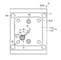
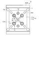
- FIG. 2 is a front view of the movable-side mold of the molding die according to the first embodiment when the number of moldings taken is one.
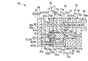
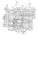
- FIG. 3A is a cross section taken along line 3A-3A shown in FIG. 2, showing the movable mold closed with respect to the stationary mold and a molded article molded.
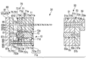
- FIG. 3B is a view showing a state in which the movable side mold is opened to the fixed side mold from the state shown in FIG. 3A.
- FIG. 3C is a view showing a state in which the molded product is pushed out by the pushing mechanism from the state shown in FIG. 3B.
- FIG. 3A is a cross section taken along line 3A-3A shown in FIG. 2, showing the movable mold closed with respect to the stationary mold and a molded article molded.
- FIG. 3B is a view showing a state in which the movable side mold is opened to
- FIG. 4 is a front view of the movable-side mold of the molding die according to the first embodiment when the number of moldings taken is four.
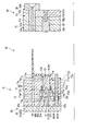
- FIG. 5A is a cross section taken along line 3A-3A shown in FIG. 2 and is a first modification of the first embodiment, wherein the movable mold is closed to the stationary mold and the molded product is molded It is a figure which shows the state which was carried out.
- FIG. 5B is a cross section taken along line 3A-3A shown in FIG. 2 and is a second modification of the first embodiment, in which the movable mold is closed to the stationary mold and the molded product is molded It is a figure which shows the state which was carried out.
- a molded article 10 as shown in FIG. 1 is injection-molded by a molding die 30 (molding apparatus) as shown in FIGS. 2, 3A, 3B, 3C and 4.
- a molded article 10 includes an optical component such as a resin lens mounted on a camera, for example.
- the molded article 10 is molded of a transparent resin material that can transmit light.
- Such materials include, for example, polycarbonate and the like.
- the molded product 10 has a first optical functional surface 11 and a second optical functional surface 13 which function as two optical functional surfaces. Further, as shown in FIG. 1, the molded article 10 is formed on the flange-shaped first edge 11 a formed on the outer peripheral portion of the first optical function surface 11 and on the outer peripheral portion of the second optical function surface 13. And a flange-like second edge 13a.
- the first optically functional surface 11 and the first edge 11 a function as the back surface of the molded article 10 formed by, for example, the movable die 70, and the second optically functional surface 13 and the second edge 13 a Functions as a surface formed by, for example, the stationary mold 50 of the molded article 10.
- the first optically functional surface 11 is recessed toward the second optically functional surface 13 with respect to the planar direction of the back surface of the molded article 10.
- the second optically functional surface 13 is recessed toward the first optically functional surface 11 with respect to the planar direction of the surface of the molded article 10.
- the molding die 30 is disposed opposite to the stationary die 50 and the stationary die 50, and the molding die 30 is placed against the stationary die 50.
- a movable side mold 70 movable to be closed (close) or open (separate).
- the stationary mold 50 is attached to a first platen (not shown) of an injection molding machine (not shown), and the movable mold 70 is attached to a second platen (not shown) of the injection molding machine.
- the fixed mold 50 and the movable mold 70 are disposed to face each other with the parting line (PL) interposed therebetween. In this state, the movable side mold 70 is supported by the second platen portion so that the movable side mold 70 can move in the opening and closing direction (left and right direction in FIG. 3A) relative to the fixed side mold 50. ing.
- the fixed side mold 50 and the movable side mold 70 are combined so that the movable side mold 70 is closed to the fixed side mold 50, for example,
- One molding cavity portion 15 and one flow passage portion 17 are formed.
- the flow path portion 17 communicates with the molding cavity portion 15, and the material of the molded product 10 flows in the molding cavity portion 15.
- the molding cavity portion 15 is formed as a space portion that defines the shape of the molded product 10.
- the molding cavity portion 15 has a stationary side cavity portion disposed in the stationary side mold 50 and a movable side cavity portion disposed in the movable side mold 70.
- the fixed cavity portion and the movable cavity portion face each other.
- the flow passage portion 17 is opposed to the tip end surface 51 a of the stationary sleeve 51 disposed in the stationary mold 50 and the tip surface 51 a, and the tip surface of the movable sleeve 71 disposed in the movable mold 70. And 71a.
- the details of the molding cavity portion 15 and the flow path portion 17 will be described later.
- the molding die 30 defines the shape of the molded article 10 by injecting the material of the molded article 10 into the molding cavity portion 15.
- the number of moldings 10 is, for example, one as shown in FIG. 2, FIG. 3A, FIG. 3B and FIG. 3C, but this number need not be limited. As shown, there may be four or more.
- the stationary mold 50 As shown in FIGS. 3A, 3B and 3C, in the stationary mold 50, the stationary sleeve 51 facing the movable sleeve 71 of the movable die 70 and the stationary sleeve 51 are placed. And a stationary side receiving plate 53.
- the stationary mold 50 further includes a stationary mold 55 housed in the stationary sleeve 51 and a sprue bush 59.
- the stationary side sleeve 51 as shown in FIGS. 3A, 3B and 3C is fixed to the stationary side receiving plate 53 by a bolt (not shown) or the like and integrated with the stationary side receiving plate 53.
- the stationary side sleeve 51 and the stationary side receiving plate 53 integrated with each other are positioned and fixed to the first mold base by a stationary side guide pin and a bolt (not shown) inserted in the first mold base (not shown). There is.
- the front end surface 51a of the stationary sleeve 51 is opposed to the movable sleeve 71 of the movable die.
- the front end surface 51a forms the above-mentioned stationary side cavity portion.
- the fixed side sleeve 51 has a fixed side storage portion 51 b that stores the fixed side molding die 55.
- the fixed side storage portion 51 b stores the fixed side molding die 55 such that, for example, the front end surface 51 a of the fixed side sleeve 51 is disposed on the same plane as the front end surface 55 a of the fixed side molding die 55.
- the fixed-side storage portion 51 b functions as a hole into which the fixed-side mold 51 is inserted and which penetrates the fixed-side sleeve 51 in the axial direction of the fixed-side sleeve 51.
- the fixed side storage portion 51 b is disposed along the axial direction of the fixed side mold 50.
- the stationary sleeve 51 is further provided along the axial direction of the stationary mold 50, and further has a sleeve side insertion port 51c into which the sprue bush 59 is inserted.
- the fixed side receiving plate 53 is disposed along the axial direction of the fixed side mold 50, and the receiving plate side insertion port 53c into which the sprue bush 59 is inserted. have.
- the stationary sleeve 51 is placed on the stationary receiving plate 53 such that the sleeve side insertion port 51 c communicates with the receiving plate side insertion port 53 c in the axial direction of the stationary mold 50.
- the stationary mold 55 functions as a nest.
- the stationary mold 55 is disposed along the axial direction of the stationary mold 50.
- the stationary mold 55 is, for example, an axial member.
- the front end surface 55 a of the stationary mold 55 faces the front end surface 75 a of the movable mold unit 75 described later.
- the front end surface 55 a of the stationary mold 55 functions as a transfer surface for transferring the second optically functional surface 13 to the material for molding the molded product 10.
- a tip end surface 51 a of the stationary sleeve 51 is disposed around the tip end surface 55 a of the stationary mold 55.
- the front end surface 51 a functions as a transfer surface for transferring the second edge 13 a to the material for forming the molded article 10.
- the stationary mold 55 is fitted in the stationary housing 51b. For this reason, the clearance between the stationary mold 55 and the inner peripheral surface of the stationary sleeve 51 in the stationary housing 51b is as small as possible.
- the stationary molding die 55 has the tip end surface of the stationary sleeve 51 with the stationary molding die 55 stored in the stationary storage portion 51b as described above. It is fixed by the fixing member 57 a so that the end 51 a is disposed on the same plane as the end surface 55 a of the fixed mold 55.
- the distal end portion of the fixing member 57 a is inserted into the fixed receiving plate 53 and fitted in a groove 55 b disposed at the proximal end of the fixed forming die 55.
- the groove 55 b is disposed on the flat base end face of the base end.
- the distal surface 51a of the stationary sleeve 51 may be disposed on the same plane as the distal surface 55a of the stationary mold 55.
- the spacer member 57b may be disposed on the
- the fixing member 57a has, for example, a screw.
- the sprue bush 59 is inserted into the sleeve side insertion port 51c and the receiving plate side insertion port 53c.
- the sprue bush 59 is disposed inside the sprue bush 59, and has an internal flow passage portion 59a through which a material for forming the molded article 10 flows.
- the inner flow passage portion 59 a is disposed, for example, along the axial direction of the stationary mold 50.
- the internal flow passage portion 59 a communicates with the flow passage portion 17.
- the material flowing through the inner flow passage portion 59a is in a molten state.
- Such sprue bush 59 has a cylindrical shape, for example, a cylindrical shape.
- Movable side mold 70 As shown in FIG. 3A, FIG. 3B and FIG. 3C, the movable side mold 70 has a movable side sleeve 71 facing the stationary side sleeve 51 and a movable side receiving plate 73 on which the movable side sleeve 71 is placed. And. Movable side mold 70 further includes a movable side forming mold unit (hereinafter referred to as unit 75) which is accommodated in movable side sleeve 71 and forms molded article 10 together with fixed side forming mold 55 of stationary side mold 50. ing.
- unit 75 a movable side forming mold unit
- the movable side mold 70 includes the molded article 10 with respect to the movable side sleeve 71 from the state of being in contact with a part of the base end surface 75b of the unit 75. It further has an ejection mechanism 80 for projecting 75 toward the stationary mold 55. The movable side mold 70 further has a return mechanism 90 for returning the unit 75 ejected by the ejection mechanism 80 to a state before ejection.
- the movable side sleeve 71 as shown in FIGS. 2, 3A, 3B and 3C is fixed to the movable side receiving plate 73 by a bolt or the like, and is integrated with the movable side receiving plate 73.
- the movable side sleeve 71 and the movable side receiving plate 73 integrated with each other are positioned and fixed to the second mold base by a movable side guide pin 70a inserted into the second mold base not shown and a bolt not shown. ing. As shown in FIGS.
- the movable side positioning pin 70b is inserted into the movable side sleeve 71, and the movable side positioning pin 70b is a fixed side positioning pin (not shown).
- the removable sleeve 51 is positioned relative to the stationary sleeve 51.
- the stationary positioning pin is disposed along the axial direction of the stationary mold 50 and is inserted into the stationary sleeve 51.
- the movable guide pin 70 a and the movable positioning pin 70 b are disposed along the axial direction of the movable mold 70.
- the tip end surface 71 a of the movable sleeve 71 faces the tip end surface 51 a of the fixed sleeve 51.
- a portion 711a of the tip end surface 71a of the movable sleeve 71 is disposed apart from a portion of the tip end surface 51a of the fixed sleeve 51, and is recessed with respect to the other portion 711b of the tip end surface 71a of the movable sleeve 71.
- the flow passage portion 17 communicates with the internal flow passage portion 59a of the sprue bush 59, and is disposed to flow a material for forming the molded product 10 to the molding cavity portion 15.
- the flow passage portion 17 is defined by a portion 711 a of the tip end surface 71 a of the movable side sleeve 71 and a portion of the tip end surface 51 a of the fixed side sleeve 51.
- the portion 711a of the tip end surface 71a, the flow path portion 17, and the molding cavity portion 15 are disposed, for example, on the left side in the drawing than PL. As shown in FIG.
- the other portion 711b of the tip end surface 71a abuts on the other portion of the tip end surface 51a of the fixed side sleeve 51.
- the other portion 711b is disposed on the PL, for example.
- the movable sleeve 71 is disposed on a portion 711a of the distal end surface 71a of the movable sleeve 71, and is disposed to form the first edge 11a. It has the recessed part 71d provided. Further, as shown in FIG. 3A, FIG. 3B and FIG. 3C, the movable side sleeve 71 further includes a sleeve side storage portion 71b for storing the unit 75 and communicating with the recess portion 71d. As shown in FIG.
- the front end surface 75a of the unit 75 is flush with the bottom surface of the recess 71d when the movable mold 70 is closed.
- the unit 75 is housed so as to be disposed in the
- the sleeve side storage portion 71 b functions as a hole into which the unit 75 is inserted and which penetrates the movable side sleeve 71 in the axial direction of the movable side sleeve 71.
- the sleeve side storage portion 71 b is disposed along the axial direction of the movable side mold 70.
- the sleeve side storage portion 71 b is coaxially arranged with the fixed side storage portion 51 b so that the unit 75 is coaxially arranged with the fixed side molding die 55.
- the sleeve side storage portion 71b is thinner than the recess portion 71d.
- the sleeve side accommodation portion 71 b has, for example, substantially the same length as a movable side molding die main body portion 751 described later of the unit 75.
- the sleeve side storage portion 71b has a convex shape which is narrowed toward the fixed side mold.
- the sleeve side storage portion 71b stores the unit 75 on the central axis of the sleeve side storage portion 71b.
- the sleeve side storage portion 71b is molded with the defining member 83 such that a defining member 83 described later of the ejection mechanism 80 and a mold side biasing member 91 described later of the return mechanism 90 surround the unit 75 all around.
- a mold side biasing member 91 is further accommodated.
- the movable side sleeve 71 has a sleeve side ejector insertion opening 71e into which an ejector pin 85 described later of the ejection mechanism 80 is inserted and a return described later of the return mechanism 90. And a sleeve side return insertion opening 71f into which the pin 93 is inserted.
- the sleeve-side ejector insertion opening 71 e and the sleeve-side return insertion opening 71 f are disposed along the axial direction of the movable die 70.
- the sleeve-side ejector insertion opening 71e is, for example, coaxially disposed with the flow passage 17 and the inner flow passage 59a.
- the sleeve side ejector insertion opening 71e and the sleeve side return insertion opening 71f are disposed on the side of the sleeve side storage 71b.
- the movable side receiving plate 73 has a receiving plate side storage portion 73b for storing the unit 75.
- the receiving plate side storage portion 73 b has a convex shape tapered toward an ejector plate 87 described later of the ejection mechanism 80.
- the receiving plate side storage portion 73 b functions as a hole into which the unit 75 is inserted and which penetrates the movable side receiving plate 73 in the axial direction of the movable side receiving plate 73.
- the receiving plate side storage portion 73 b is disposed along the axial direction of the movable side mold 70.
- the tip end portion of the receiving plate side storage portion 73 b communicates with the proximal end portion of the sleeve side storage portion 71 b in the axial direction of the movable side mold 70.
- the base end portion of the receiving plate side storage portion 73 b communicates with the outside.
- the receiving plate side storage portion 73b stores the unit 75 on the central axis of the receiving plate side storage portion 73b. Then, the receiving plate side storage portion 73 b protrudes so that a protruding member 81 described later of the protruding mechanism 80 is inserted into the receiving plate side storage portion 73 b, and the defining member 83 of the protruding mechanism 80 surrounds the unit 75 all around. The member 81 and the defining member 83 are further accommodated.
- the movable side receiving plate 73 is a receiving plate side ejector insertion port 73e into which the ejector pin 85 is inserted, and a receiving plate side return into which the return pin 93 is inserted. And an insertion port 73f.
- the receiving plate side ejector insertion port 73 e and the receiving plate side return insertion port 73 f are disposed along the axial direction of the movable side mold 70.
- the receiving plate side ejector insertion port 73e is, for example, disposed coaxially with the flow passage portion 17 and the inner flow passage portion 59a.
- the receiving plate side ejector insertion port portion 73e and the receiving plate side return insertion port portion 73f are disposed on the side of the sleeve side storage portion 71b.
- the sleeve side storage portion 71b communicates with the receiving plate side storage portion 73b in the axial direction of the movable side mold 70, and the sleeve side ejector
- the insertion port 71e is placed on the movable side receiving plate 73 such that the receiving side ejector inserting port 73e communicates with the receiving side ejector inserting port 73e, and the sleeve side return inserting port 71f communicates with the receiving side return inserting port 73f.
- the unit 75 functions as a nest.
- the unit 75 is disposed along the axial direction of the movable mold 70.
- the unit 75 is, for example, an axial member.
- the unit 75 is disposed coaxially with the stationary mold 55 and faces the stationary mold 55.
- the front end surface 75 a of the unit 75 faces the front end surface 55 a of the stationary mold 55.
- the front end surface 75 a of the unit 75 functions as a transfer surface for transferring the first optically functional surface 11 to the material for molding the molded product 10.
- a depressed portion 71d which is a part 711a of the front end surface 71a of the movable side sleeve 71 is disposed.
- the recess 71 d functions as a transfer surface for transferring the first edge 11 a to the material for forming the molded product 10.
- the unit 75 is fitted in the sleeve side storage portion 71b. For this reason, the clearance between the unit 75 and the inner circumferential surface of the movable sleeve 71 in the sleeve housing 71b is as small as possible.
- the sleeve side storage portion 71b is such that the unit 75 is protruded by the pushing mechanism 80 and the unit 75 is returned to the state before pushing by the return mechanism 90.
- the receiving plate side storage portion 73b is separate from the ejection mechanism 80, and is not connected to the ejection mechanism 80 by, for example, fastening and fitting.
- such a unit 75 has a movable side molding die main body (hereinafter referred to as a main body 751) for molding the molded product 10, and a main body 751 and an ejection mechanism. And an intervening portion 753 interposed therebetween.
- the main body portion 751 functions as a distal end portion of the unit 75
- the intervening portion 753 functions as a proximal end portion of the unit 75.
- the intervening portion 753 is separate from the main body portion 751, and is replaceable with respect to the main body portion 751.
- the main body 751 has a front end surface 75a of the unit 75 disposed at the front end of the main body 751.
- the main body 751 is, for example, an axial member.
- the intervening portion 753 has a distal end portion 753a fitted to the main body portion 751 and a proximal end portion 753b having a proximal end surface 75b of the unit 75.
- the distal end portion 753 a is detachably fitted in a groove portion 751 c disposed in the proximal end portion of the main body portion 751.
- the outer peripheral surface of the tip portion 753a is in close contact with the inner peripheral surface of the groove 751c.
- the proximal end surface of the intervening portion 753 functions as the proximal end surface 75 b of the unit 75.
- the proximal end surface 75b of the unit 75 has a flat plate shape.
- the intervening portion 753 is disposed along the axial direction of the movable side mold 70.
- the intervening portion 753 has, for example, a convex shape.
- the proximal end portion 753b of the interposed portion 753 of the interposed portion 753 is the receiving plate storage portion 73b. It protrudes toward the ejector board 87 side, and it arrange
- the base end portion 753b of the intervening portion 753 receives the sleeve side accommodation portion 71b and the receiving plate side accommodation.
- the intervening portion 753 is disposed to be inserted into the portion 73b.
- the interposition part 753 is configured such that the movable side mold 70 is inserted so as to insert the receiving plate side storage part 73b and the sleeve side storage part 71b by the protrusion of the protrusion mechanism 80. It is movable along the axial direction of The intervening portion 753 projects the unit 75 such that the tip surface 75a of the unit 75 moves from the bottom surface of the recess 71 d toward the stationary mold 50 by this movement. Protruding is performed, for example, to take out the molded article 10.
- the protrusion mechanism 80 has, for example, the distal end surface 75a of the unit 75 from the distal end surface 71a of the movable sleeve 71, for example, the bottom of the recess 71d to the fixed mold 55
- the unit 75 abuts on a part of the base end surface 75 b of the unit 75 so as to be protruded toward the fixed side molding die 55 with respect to the movable side sleeve 71 from the abutted state.
- the ejection mechanism 80 makes point contact with a part of the base end surface 75b of the unit 75 at the time of abutment, and projects the unit 75 with respect to the movable sleeve 71 by point contact.
- the ejection mechanism 80 has an ejection member 81 for ejection, and the ejection member 81 makes point contact with the proximal end surface 75b of the unit 75. It has a convex protruding side curved surface portion 81a.
- the protruding side curved surface portion 81 a is disposed at the tip of the protruding member 81.
- the protruding side curved surface portion 81a only makes point contact with the proximal end surface of the intervening portion 753, which is the proximal end surface 75b of the unit 75, and does not fit or fasten to the proximal end surface 75b.
- the ejection member 81 can be separated from the intervening portion 753 by the return mechanism 90.
- the protrusion-side curved surface portion 81 a can be separated from the proximal end surface 75 b by the thickness of the defining member 83 described later and the return mechanism 90.
- the protruding member 81 is separate from the intervening portion 753. That is, the protrusion member 81 is not connected to the unit 75 including the interposition part 753 by, for example, fastening and fitting.
- the protruding member 81 is disposed along the axial direction of the movable mold.
- the protruding member 81 is disposed coaxially with the intervening portion 753.
- the protruding member 81 protrudes the intervening portion 753.
- the protruding members 81 are provided in the same number as the units 75, and the protruding members 81 are provided for each unit 75. That is, one ejection member 81 ejects one unit 75.
- the protrusion mechanism 80 is provided in the intervening portion 753 of the unit 75, and defines a defining member 83 which defines the position and the amount of protrusion of the unit 75 with respect to the movable sleeve 71. I have further.
- the protrusion amount of the unit 75 refers to the amount of movement of the intervening portion 753, in other words, the amount of movement of the protrusion member 81.
- the defining member 83 functions as a spacer member such that the thickness of the defining member 83 defines the amount of protrusion of the unit 75.
- the defining member 83 has, for example, a ring shape.
- the tip end portion 753a of the intervening portion 753 has the defining member 83 inserted therethrough.
- the defining member 83 is movable along the axial direction of the movable side mold 70 as described above together with the intervening portion 753. Therefore, as shown in FIG. 3C, when protruding, the defining member 83 is stored in the sleeve side storage portion 71b and abuts on the recessed portion 71g of the movable side sleeve 71 in the sleeve side storage portion 71b. When the defining member 83 abuts, the defining member 83 defines the amount of protrusion.
- the defining member 83 has a flat portion 83a facing the recess 71g and in surface contact with the recess 71g. As shown in FIGS. 3A and 3B, when the molded product 10 is formed, the defining member 83 is stored in the receiving plate side storage portion 73b, and a depression of the movable side receiving plate 73 in the receiving plate side storage portion 73b. It abuts on the portion 73g. When the defining member 83 abuts, the defining member 83 defines the position of the unit 75 with respect to the movable sleeve 71 when the molded article 10 is formed. This position is the position before the ejection of the ejection mechanism 80 is performed, and is the reference position of the unit 75.
- the defining member 83 has a flat portion 83b that faces the recess 73g and abuts on the recess 73g. As shown in FIGS. 3A and 3B, when the unit 75 is at the reference position, the flat portion 83a is separated from the recess 71g. At the time of protrusion shown in FIG. 3C, the flat portion 83b is separated from the recess portion 73g.
- the ejector mechanism 80 includes an ejector pin 85 inserted into the receiving plate side ejector insertion opening 73e and the sleeve side ejector insertion opening 71e, and the movable side reception plate It further has an ejector plate 87 which is disposed to face 73 and supports the ejector member 81, the ejector pin 85 and the return pin 93.
- the ejector pin 85 is, for example, a rod-like member, and is disposed along the axial direction of the movable-side mold 70.
- the ejector plate 87 includes a first plate member 87a, and a movable side receiving plate 73 and a first plate member 87a in the axial direction of the movable side mold 70. And a second plate member 87b placed on the first plate member 87a. On the first plate member 87a, the proximal end of the ejector member 81, the proximal end of the ejector pin 85, and the proximal end of the return pin 93 are placed.
- the second plate member 87b has a fitting opening 87c in which the projecting member 81 is fitted, an insertion opening 87d through which the ejector pin 85 is inserted, and an insertion opening 87e through which the return pin 93 is inserted.
- the ejector member 81 fits the fitting opening 87c, the ejector pin 85 is inserted through the insertion opening 87d and placed on the first plate member 87a, and the return pin 93 is inserted through the insertion opening 87e and is the first plate It is placed on the member 87a.
- the second plate member 87b protrudes by holding the proximal end of the ejector member 81, the proximal end of the ejector pin 85, and the proximal end of the return pin 93 together with the first plate member 87a.
- the member 81, the ejector pin 85 and the return pin 93 are supported together with the first plate member 87a.
- the ejector plate 87 is pressed by a mechanism (not shown) when the movable mold 70 is closed to the fixed mold 50.
- the ejector plate 87 moves along the axial direction of the movable side mold 70 by pressing and approaches the movable side receiving plate 73.
- the ejector plate 87 pushes the ejection member 81, the ejector pin 85, and the return pin 93 toward the stationary mold 50 along the axial direction of the movable mold 70. Since the ejector plate 87 moves along the axial direction of the movable mold 70, the pushing direction of the ejector plate 87 is along the axial direction of the movable mold 70.
- the ejector plate 87 is moved by the movable-side mold 70 by the ejector-side biasing member 95 of the return mechanism 90, which will be described later, when the movable-side mold 70 opens relative to the fixed-side mold 50. It leaves from the movable side receiving plate 73 along the axial direction of.
- the return mechanism 90 is provided by the ejection mechanism 80 such that the distal end surface 75a of the unit 75 is disposed on the same plane as the distal end surface 71a of the movable sleeve 71.
- the pushed out unit 75 is returned to the state before pushing out.
- the state before the protrusion indicates, for example, a position where the tip end surface 75a of the unit 75 is disposed on the left side of the PL, specifically, on the same plane as the bottom surface of the depressed portion 71d.
- the state before the extrusion is set as desired depending on the shape of the molded article 10 and the like.
- the return mechanism 90 attaches the unit 75 in the axial direction of the movable side mold 70 via the defining member 83 so that the unit 75 returns to the state before projecting.
- a mold side biasing member 91 having a biasing force is provided.
- the molding die side biasing member 91 is disposed to wind the proximal end portion of the main body portion 751.
- the molding die side biasing member 91 is disposed in the sleeve side storage portion 71 b and the receiving plate side storage portion 73 b.
- the tip end of the mold side biasing member 91 is fixed to the movable side sleeve 71.
- the base end of the mold side biasing member 91 is fixed to the defining member 83.
- Such a mold side biasing member 91 biases the unit 75 toward the ejector plate 87 via the defining member 83 and the intervening portion 753.
- the molding die side biasing member 91 biases the unit 75 so that, for example, the tip end surface 75a of the unit 75 which is in the state before protruding is disposed on the same plane as the bottom surface of the recess 71d.
- the mold side biasing member 91 biases the unit 75 as described above after the molded article 10 is taken out.
- the defining member 83 is stored in the receiving plate side storage portion 73b, and abuts on the recessed portion 73g of the movable side receiving plate 73 in the receiving plate side storage portion 73b.
- the defining member 83 and the mold side biasing member 91 define the state before the protrusion. That is, the molding die side biasing member 91 biases the defining member 83 in the axial direction of the movable side mold 70 such that the defining member 83 abuts on the recessed portion 73 g of the movable side receiving plate 73.
- the mold side biasing member 91 has, for example, a winding spring that expands and contracts in the axial direction of the mold side biasing member 91.
- the mold side biasing member 91 acts simultaneously with the ejector side biasing member 95 described later.
- the return mechanism 90 is supported by the ejector plate 87, and is a return pin inserted into the receiving plate side return insertion port 73f and the sleeve side return insertion port 71f. It further has 93.
- the return mechanism 90 further includes an ejector-side biasing member 95 disposed to wind the return pin 93.
- the ejector-side biasing member 95 has a biasing force that separates the ejector plate 87 including the return pin 93, the ejector pin 85, and the projecting member 81 from the movable side receiving plate 73 in the axial direction of the movable side mold 70.
- the return pin 93 is, for example, a rod-like member, and is disposed along the axial direction of the movable mold.
- the ejector-side biasing member 95 As shown in FIG. 3A, FIG. 3B and FIG. 3C, the ejector-side biasing member 95 has a distal end inserted into the receiving plate-side return insertion port 73f and a proximal end attached to the ejector plate 87. I am The ejector-side biasing member 95 has, for example, a winding spring that expands and contracts in the axial direction of the ejector-side biasing member 95.
- the movable side mold 70 is fixed to the stationary side mold 50 so that the other portion 711b of the distal end surface 71a of the movable side sleeve 71 abuts on the other portion of the distal end surface 51a of the stationary side sleeve 51. It is closed against.
- the ejector side biasing member 95 extends in the axial direction of the ejector side biasing member 95, and the ejector plate 87 is pulled away from the movable side receiving plate 73 in the axial direction of the movable side mold 70.
- the ejector plate 87 is biased to move.
- the ejector plate 87 including the return pin 93, the ejector pin 85, and the ejector member 81 is separated from the movable side receiving plate 73.
- molding die side biasing member 91 is extended in the axial direction of the shaping
- the flat portion 83b of the defining member 83 abuts on the depressed portion 73g of the movable side receiving plate 73, the unit 75 including the defining member 83 can stably define the state before the protrusion with high reproducibility. Thereby, the tip end surface 75a of the unit 75 is positioned on the same plane as the bottom surface of the recess 71d. The unit 75 returns to the state before the ejection.
- the flow path portion 17 and the molding cavity portion 15 are defined by the above.
- the material for molding the molded article 10 is filled in the molten state from the inner flow passage portion 59a to the molding cavity portion 15 through the flow passage portion 17.
- the flat portion 83b of the defining member 83 abuts on the recessed portion 73g, so that the unit 75 is stably defined with good reproducibility for the state before the protrusion. For this reason, filling is performed in a prescribed state, and the precision of the molded article 10 becomes uniform. Once the desired time has elapsed or upon cooling, the material solidifies.
- the movable side mold 70 opens relative to the stationary side mold 50 such that the tip end surface 71 a of the movable side sleeve 71 is separated from the tip end surface 51 a of the stationary side sleeve 51.
- the ejector plate 87 is pressed by a mechanism (not shown), and moves along the axial direction of the movable mold 70 by pressing to approach the movable receiving plate 73.
- the ejector member 81, the ejector pin 85 and the return pin 93 are pushed out toward the stationary mold 50 along the axial direction of the movable mold 70.
- this extrusion carries out the ejection process.
- the protrusion mechanism 80 abuts on a part of the base end surface 75 b of the unit 75 so that the tip surface 75 a of the unit 75 is protruded from the tip surface 71 a of the movable sleeve 71 toward the stationary mold 50.
- the ejection mechanism 80 projects the unit 75 toward the stationary mold 50 with respect to the movable sleeve 71.
- the protruding member 81 abuts on the intervening portion 753.
- the protruding curved surface portion 81a makes point contact with the proximal end surface 75b of the unit 75. Then, the projecting member 81 projects the unit 75 toward the stationary mold 50 with respect to the movable sleeve 71 from this state.
- the movable side mold 70 when the movable side mold 70 is assembled, if the unit 75, the projecting member 81 and the ejector plate 87 are integrated with each other, for example, due to the stacking error and assembling accuracy of the processing error of these members.
- the axial direction of the ejection member 81 is not disposed orthogonal to the planar direction of the ejector plate 87, in other words, the axial direction of the ejection member 81 is oblique to the ejection direction of the ejector plate 87
- the pushing direction of the ejector plate 87 is along the axial direction of the movable side mold 70 as described above.
- the unit 75 can not receive the ejection force straight along the axial direction of the unit 75, and receives an ejection force diagonal to the axial direction of the unit 75. For this reason, the unit 75 does not move along the axial direction of the unit 75, but may move obliquely with respect to the axial direction of the unit 75. If the unit 75 moves obliquely while the clearance between the unit 75 and the inner peripheral surface of the movable sleeve 71 (for example, the sleeve side storage portion 71b) is extremely small, the unit 75 is movable. There is a risk of contact with the inner circumferential surface of the side sleeve 71.
- the unit 75 may slide on the inner peripheral surface of the movable sleeve 71 after coming into contact. As a result, the unit 75 may be rubbed by sliding, that is, a risk of galling may occur. In some cases, the unit 75 is not pushed out, which may cause the molded article 10 not to be removed. The occurrence of galling also leads to a decrease in the accuracy of the molded article 10.
- the axial direction of the projecting member 81 is, for example, the ejector plate 87 depending on the assembly accuracy. There is a possibility that they are not disposed orthogonal to the plane direction. In other words, there is a possibility that the axial direction of the projecting member 81 may be diagonally displaced with respect to the axial direction of the movable side mold 70. As a result, the unit 75 may also be accommodated in the movable sleeve 71 in a state of being obliquely shifted with respect to the axial direction of the movable mold 70.
- the unit 75 When the unit 75 is protruded in this state, as described above, the unit 75 may come in contact with the inner peripheral surface of the movable sleeve 71. Therefore, as described above, there is a possibility that galling may occur. In some cases, the unit 75 is not pushed out, which may cause the molded article 10 not to be taken out. The occurrence of galling also leads to a decrease in the accuracy of the molded article 10.
- the intervening portion 753 of the unit 75 is not connected to the projecting member 81, so the above-mentioned point contact is performed without being affected by the assembly accuracy. Be done.
- the protrusion at the point contact is performed along the axial direction of the unit 75 and is not performed obliquely to the axial direction of the unit 75. Therefore, the unit 75 moves along the axial direction of the unit 75 and is prevented from moving obliquely with respect to the axial direction of the unit 75.
- the unit 75 has the inner circumferential surface of the movable sleeve 71 in the sleeve side storage portion 71 b. It is prevented that it abuts. In addition, the unit 75 is prevented from sliding on the inner peripheral surface of the movable sleeve 71 by the contact. Then, the unit 75 is prevented from being rubbed by sliding, and the occurrence of galling is suppressed. As a result, the unit 75 is reliably ejected and the molded article 10 is reliably removed. Further, since the occurrence of galling is suppressed, the molded article 10 is molded with high accuracy.
- the protrusion member 81 is arrange
- the above-described point contact is reliably carried out for each projecting member 81. For this reason, even when a plurality of molded products 10 are taken out, the occurrence of galling is suppressed, the unit 75 is reliably protruded, the molded products 10 are reliably taken out, and the molded products 10 are high. Molded to accuracy.
- the ejector pin 85 ejects the material of the molded product 10 during the ejection.
- This material is integral with the molded product 10 and disposed in the internal flow passage portion 59a.
- the defining member 83 moves along with the unit 75 in the axial direction of the movable side mold 70. Then, the mold side biasing member 91 is pushed by the defining member 83 and contracted. Further, the defining member 83 abuts on the recessed portion 71g of the movable side sleeve 71 in the sleeve side storage portion 71b. When the defining member 83 abuts, the defining member 83 defines the amount of protrusion. In addition, the ejector-side biasing member 95 is shrunk in the protrusion.
- the ejector plate 87 When the molded product 10 is removed from the movable mold 70, the ejector plate 87 is released from the pressure of a mechanism (not shown). As a result, the ejector-side biasing member 95 extends, and the ejector-side biasing member 95 separates the ejector plate 87 from the movable side receiving plate 73 along the axial direction of the movable side mold 70. The ejector member 81, the ejector pin 85 and the return pin 93 move along with the ejector plate 87 in the axial direction of the movable mold 70.
- the molding die side biasing member 91 extends in the axial direction of the molding die side biasing member 91, and biases the defining member 83 toward the recessed portion 73g of the movable side receiving plate 73 in the receiving plate side storage portion 73b. .
- the unit 75 including the defining member 83 is stably defined with high reproducibility in the state before the protrusion.
- the tip end surface 75a of the unit 75 is positioned on the same plane as the bottom surface of the recess 71d. That is, the unit 75 stably returns to the state before the protrusion with good reproducibility.
- the protrusion-side curved surface portion 81 a may be separated from the proximal end surface 75 b of the unit 75 depending on the thickness of the defining member 83 and the amount of biasing of the mold side biasing member 91.
- the ejection mechanism 80 abuts on a part of the base end surface 75 b of the unit 75 and projects the unit 75 toward the stationary mold 50 with respect to the movable sleeve 71 from the abutted state. .
- point contact is performed at the time of abutment.
- the protrusion at the point contact is performed along the axial direction of the unit 75.
- the unit 75 can be moved along the axial direction of the unit 75, and it can be prevented from moving obliquely with respect to the axial direction of the unit 75.
- the unit 75 even when the clearance between the unit 75 and the inner peripheral surface of the movable sleeve 71 is extremely small, the unit 75 abuts on the inner peripheral surface of the movable sleeve 71. Can be prevented. Further, in the present embodiment, it is possible to prevent the unit 75 from sliding on the inner peripheral surface of the movable sleeve 71 due to the contact. And in this embodiment, it can prevent that unit 75 is rubbed by sliding, and it can control that galling occurs. In the present embodiment, as a result, the unit 75 can be reliably protruded, and the molded product 10 can be reliably taken out. Further, in the present embodiment, since the occurrence of galling is suppressed, the molded article 10 can be molded with high accuracy.
- the protruding members 81 are disposed for each unit 75. Even in such a case, in the present embodiment, the point contact described above is reliably performed for each of the protruding members 81. For this reason, in the present embodiment, even when a plurality of molded products 10 are taken out, the occurrence of galling can be suppressed, and the unit 75 can be reliably protruded, and the molded products 10 can be reliably taken out.
- the molded article 10 can be molded with high accuracy.
- the occurrence of galling can be suppressed without being affected by the assembly accuracy, the molded product 10 with high accuracy can be molded, and the molded product 10 can be reliably taken out.
- the base end surface 75b of the unit 75 has a flat plate shape, and the protruding member 81 has a protruding protruding curved surface portion 81a.
- the protruding member 81 is disposed for each unit 75. For this reason, in the present embodiment, even when a plurality of molded articles 10 are taken out at one time, it is effective.
- the main body portion 751 and the intervening portion 753 are disposed, and the intermediate portion 753 is separate from the main body portion 751 and is replaceable with respect to the main body portion 751. Therefore, in the present embodiment, the shape and size of the proximal end surface 75b of the unit 75 for point contact can be freely adjusted by replacing the intervening portion 753.
- the intervening portion 753 may be integral with the main body portion 751. Thereby, the configuration of the unit 75 can be simplified.
- the protrusion amount of the unit 75 can be freely defined according to the shape of the molded product 10 by the thickness of the defining member 83.
- the state before the unit 75 is protruded by the mold side biasing member 91 and the defining member 83. Can be returned to Thereby, when the material of the molded article 10 is filled in the molding cavity portion 15, it is possible to suppress the unit 75 from retreating due to the pressure of the material, and it is possible to suppress the molding failure caused by the retreat. Further, in the present embodiment, the thickness of the defining member 83 can freely define the state before the unit 75 protrudes according to the shape of the molded product 10.
- the intervening portion 753 of the unit 75 has a convex mold side curved surface portion 75 c disposed on the proximal end surface 75 b of the unit 75.
- the ejection mechanism 80 has an ejection member 81 for ejection, and the ejection member 81 has a convex projection-side curved surface in point contact with the mold-side curved surface portion 75c. It has a portion 81a.
- the projecting member 81 is disposed for each unit 75 as in the first embodiment.
- the intervening portion 753 of the unit 75 has a convex mold side curved surface portion 75 c disposed on the proximal end surface 75 b of the unit 75.
- the ejection mechanism 80 has an ejector plate 87 that functions as a flat plate that is in point contact with the mold side curved surface 75c.
- One ejector plate 87 is disposed as an ejection member, and contacts the molding die-side curved surface portion 75c of all the units 75.
- the ejector plate 87 functioning as an ejection member does not have to be provided for each unit 75, and the ejector plate 87 can be shared for each unit 75. Therefore, in this modification, the configuration of the ejection mechanism 80 can be simplified, and the molding die 30 can be made compact and compact. Further, in the present embodiment, the extruding member 81 can be omitted, and the molding die 30 can be made compact.
Landscapes
- Engineering & Computer Science (AREA)
- Mechanical Engineering (AREA)
- Manufacturing & Machinery (AREA)
- Moulds For Moulding Plastics Or The Like (AREA)
- Cartons (AREA)
Abstract
成形金型(30)の可動側金型(70)は、可動側スリーブ(71)と、可動側スリーブ(71)に収納され、固定側成形型(55)と共に成形品(10)を成形する可動側成形型ユニット(75)とを有している。可動側金型(70)は、可動側成形型ユニット(75)の先端面(75a)が可動側スリーブ(71)の先端面(71a)から固定側成形型(55)に向かって突き出されるように、可動側成形型ユニット(75)の基端面(75b)の一部に当接し、当接した状態から可動側スリーブ(71)に対して可動側成形型ユニット(75)を固定側成形型(55)に向かって突き出す突き出し機構(80)をさらに有している。
Description
本発明は、成形品を成形する成形金型及び成形金型を用いる製造方法に関する。
例えば特許文献1と特許文献2とは、偏芯精度が高い成形品を成形する成形金型を開示している。成形品は、例えば、レンズなどの光学素子を有している。
この成形金型の可動側金型は、可動側スリーブと、可動側スリーブに配設され、固定側金型と共に成形品を成形する可動側成形型とを有している。可動側成形型は可動側スリーブと高精度で嵌合しているため、可動側成形型と可動側スリーブの内周面との間のクリアランスは限りなく小さくなっている。
この状態で、可動側成形型は、可動側成形型の基端面において、軸状の突き出し部材の先端部と嵌合している。この場合、例えば、突き出し部材の先端部の外周面は、可動側成形型の基端面に配設されている溝部の内周面に密着している。また突き出し部材の基端部はエジェクタ板に支持されている。つまり、可動側成形型と突き出し部材とエジェクタ板とは、互いに一体となっている。
エジェクタ板が押圧されることによって、エジェクタ板は可動側金型の軸方向に沿って突き出し部材を押し出すこととなる。これにより突き出し部材は、可動側スリーブに対して可動側成形型を固定側金型に向かって突き出すこととなる。よって可動側成形型の先端面は可動側スリーブの先端面から突き出され、成形品は取り出される。
このように突き出し部材とエジェクタ板とは、成形品を押し出す、言い換えると成形品を突き出す突き出し機構として機能する。
可動側金型が組み立てられる際に、前記したように、可動側成形型と突き出し部材とエジェクタ板とが互いに一体となる。この場合、例えば複数の部品の加工誤差の積み重ね及び組立精度によって、例えば、突き出し部材の軸方向がエジェクタ板の平面方向に対して直交して配設されていない虞が生じる。言い換えると、突き出し部材の軸方向がエジェクタ板の押し出し方向に対して斜めにずれる虞が生じる。なおエジェクタ板の押し出し方向は、前記したように、可動側金型の軸方向に沿っている。
このような場合、可動側成形型は、可動側成形型の軸方向に沿ってまっすぐに突き出し力を受けることができず、可動側成形型の軸方向に対して斜めの突き出し力を受けることとなる。このため、可動側成形型は、可動側成形型の軸方向に沿って移動せず、可動側成形型の軸方向に対して斜めに移動する虞が生じる。前記したように可動側成形型と可動側スリーブの内周面との間のクリアランスは、限りなく小さくなっている。このため、前記したように可動側成形型が斜めに移動してしまうと、可動側成形型は、可動側スリーブの内周面に当接してしまう虞が生じる。また可動側成形型は、当接した後において可動側スリーブの内周面を摺動する虞が生じる。これにより、可動側成形型は摺動によってこすれてしまう、つまり、かじりが発生してしまう虞が生じる。場合によっては、可動側成形型は突き出されず、成形品が取り出されない虞が生じる。またかじりの発生は、成形品の精度低下につながる。
このような場合、可動側成形型は、可動側成形型の軸方向に沿ってまっすぐに突き出し力を受けることができず、可動側成形型の軸方向に対して斜めの突き出し力を受けることとなる。このため、可動側成形型は、可動側成形型の軸方向に沿って移動せず、可動側成形型の軸方向に対して斜めに移動する虞が生じる。前記したように可動側成形型と可動側スリーブの内周面との間のクリアランスは、限りなく小さくなっている。このため、前記したように可動側成形型が斜めに移動してしまうと、可動側成形型は、可動側スリーブの内周面に当接してしまう虞が生じる。また可動側成形型は、当接した後において可動側スリーブの内周面を摺動する虞が生じる。これにより、可動側成形型は摺動によってこすれてしまう、つまり、かじりが発生してしまう虞が生じる。場合によっては、可動側成形型は突き出されず、成形品が取り出されない虞が生じる。またかじりの発生は、成形品の精度低下につながる。
また前記したように、可動側成形型と突き出し部材とエジェクタ板とが互いに一体である場合、組立精度によって、例えば、突き出し部材の軸方向がエジェクタ板の平面方向に対して直交して配設されていない虞が生じる。言い換えると、突き出し部材の軸方向が可動側金型の軸方向に対して斜めにずれる虞が生じる。これにより、可動側成形型も可動側金型の軸方向に対して言い換えると可動側スリーブの軸方向に対して斜めにずれた状態で可動側スリーブに収納される虞が生じる。この状態で可動側成形型が突き出されると、前記したように、可動側成形型は、可動側スリーブの内周面に当接してしまう虞が生じる。よって、前記したように、摺動及びかじりが発生する虞が生じる。場合によっては、可動側成形型は突き出されず、成形品が取り出されない虞が生じる。またかじりの発生は、成形品の精度低下につながる。
なお一度に複数の成形品が取り出される場合、突き出し部材は、成形品ごとに配設される。このため、組立精度が突き出し部材毎に異なると、可動側成形型ユニット毎にかじりが発生し、各成形品の精度にばらつきが生じる。このように一度に複数の成形品が取り出されるほど、かじりの影響は顕著となる。またこの場合、前記したようなかじりの発生は、成形品の精度低下につながる。
このため、組立精度に影響されることなく、かじりの発生を抑制でき、高精度の成形品を成形でき、成形品を確実に取り出すことが要望されている。
本発明は、これらの事情に鑑みてなされたものであり、組立精度に影響されることなく、かじりの発生を抑制でき、高精度の成形品を成形でき、成形品を確実に取り出すことができる成形金型及び成形金型を用いる製造方法を提供することを目的とする。
本発明の成形金型の一態様は、固定側金型と、前記固定側金型に対向して配設され、前記固定側金型に対して閉じるまたは開くように可動する可動側金型とを有する成形金型であって、前記可動側金型は、可動側スリーブと、前記可動側スリーブに収納され、前記固定側金型の固定側成形型と共に成形品を成形する可動側成形型ユニットと、前記可動側成形型ユニットの先端面が前記可動側スリーブの先端面から前記固定側成形型に向かって突き出されるように、前記可動側成形型ユニットの基端面の一部に当接し、当接した状態から前記可動側スリーブに対して前記可動側成形型ユニットを前記固定側成形型に向かって突き出す突き出し機構と、を具備する。
本発明の製造方法の一態様は、前記に記載の成形金型を用い、前記可動側スリーブに収納され、前記成形品を成形する前記可動側成形型ユニットにおいて、前記可動側成形型ユニットの先端面が前記可動側スリーブの先端面から前記固定側成形型に向かって突き出されるように、前記突き出し機構を前記可動側成形型ユニットの基端面の一部に当接させた状態から前記突き出し機構によって前記可動側スリーブに対して前記可動側成形型ユニットを前記固定側成形型に向かって突き出す突き出し工程を具備する。
以下、図面を参照して本発明の実施形態について詳細に説明する。
[第1の実施形態]
[構成]
図1と図2と図3Aと図3Bと図3Cと図4とを参照して第1の実施形態について説明する。なお一部の図面では、図示の明瞭化のために、一部の部材の図示を省略している。
[第1の実施形態]
[構成]
図1と図2と図3Aと図3Bと図3Cと図4とを参照して第1の実施形態について説明する。なお一部の図面では、図示の明瞭化のために、一部の部材の図示を省略している。
[成形品10]
図1に示すような成形品10は、図2と図3Aと図3Bと図3Cと図4とに示すような成形金型30(成形装置)によって射出成形される。このような成形品10は、例えばカメラに搭載される樹脂製のレンズといった、光学部品を含む。成形品10は、光が透過可能な透明な樹脂材料によって成形される。このような材料は、例えばポリカーボネートなどを含む。
図1に示すような成形品10は、図2と図3Aと図3Bと図3Cと図4とに示すような成形金型30(成形装置)によって射出成形される。このような成形品10は、例えばカメラに搭載される樹脂製のレンズといった、光学部品を含む。成形品10は、光が透過可能な透明な樹脂材料によって成形される。このような材料は、例えばポリカーボネートなどを含む。
図1に示すように、成形品10は、2つの光学機能面として機能する第1の光学機能面11と第2の光学機能面13とを有している。また図1に示すように、成形品10は、第1の光学機能面11の外周部位に形成されるフランジ状の第1の縁部11aと、第2の光学機能面13の外周部位に形成されるフランジ状の第2の縁部13aとをさらに有している。第1の光学機能面11と第1の縁部11aとは成形品10の例えば可動側金型70によって形成される裏面として機能し、第2の光学機能面13と第2の縁部13aとは成形品10の例えば固定側金型50によって形成される表面として機能する。
図1に示すように、第1の光学機能面11は、成形品10の裏面の平面方向に対して、第2の光学機能面13に向かって窪んでいる。第2の光学機能面13は、成形品10の表面の平面方向に対して、第1の光学機能面11に向かって窪んでいる。
[成形金型30]
図2と図3Aと図3Bと図3Cとに示すように、成形金型30は、固定側金型50と、固定側金型50に対向して配設され、固定側金型50に対して閉じる(近づく)または開く(離れる)ように可動する可動側金型70とを有している。固定側金型50は図示しない射出成形機の図示しない第1のプラテン部に取付けられ、可動側金型70は射出成形機の図示しない第2のプラテン部に取付けられている。固定側金型50と可動側金型70とは、パーティングライン(PL)を挟んで互いに対向して配設されている。この状態で、可動側金型70は、可動側金型70が固定側金型50に対し開閉方向(図3A中で左右方向)に移動可能となるように、第2のプラテン部に支持されている。
図2と図3Aと図3Bと図3Cとに示すように、成形金型30は、固定側金型50と、固定側金型50に対向して配設され、固定側金型50に対して閉じる(近づく)または開く(離れる)ように可動する可動側金型70とを有している。固定側金型50は図示しない射出成形機の図示しない第1のプラテン部に取付けられ、可動側金型70は射出成形機の図示しない第2のプラテン部に取付けられている。固定側金型50と可動側金型70とは、パーティングライン(PL)を挟んで互いに対向して配設されている。この状態で、可動側金型70は、可動側金型70が固定側金型50に対し開閉方向(図3A中で左右方向)に移動可能となるように、第2のプラテン部に支持されている。
図3Aに示すように、本実施形態では、可動側金型70が固定側金型50に対して閉じられるように固定側金型50と可動側金型70とが組合された際に、例えば1つの成形キャビティ部15と1つの流路部17とが形成される。流路部17は、成形キャビティ部15と連通し、成形キャビティ部15に成形品10の材料を流す。この成形キャビティ部15は、成形品10の形状を規定する空間部として形成される。成形キャビティ部15は、固定側金型50に配設される固定側キャビティ部と、可動側金型70に配設される可動側キャビティ部とを有している。固定側キャビティ部と可動側キャビティ部とは、互いに対向している。流路部17は、固定側金型50に配設される固定側スリーブ51の先端面51aと、先端面51aに対向し、可動側金型70に配設される可動側スリーブ71の先端面71aとによって規定される。成形キャビティ部15と流路部17との詳細については、後述する。
成形金型30は、成形品10の材料が成形キャビティ部15に注入されることで成形品10の形状を規定することとなる。
成形金型30において、成形品10の取り数は、図2と図3Aと図3Bと図3Cとに示すように例えば1個であるが、この数は限定される必要はなく、図4に示すように4個でもよいし、複数であってもよい。
[固定側金型50]
図3Aと図3Bと図3Cとに示すように、固定側金型50は、可動側金型70の可動側スリーブ71に対向している固定側スリーブ51と、固定側スリーブ51が載置される固定側受板53とを有している。固定側金型50は、固定側スリーブ51に収納される固定側成形型55と、スプルーブッシュ59とをさらに有している。
図3Aと図3Bと図3Cとに示すように、固定側金型50は、可動側金型70の可動側スリーブ71に対向している固定側スリーブ51と、固定側スリーブ51が載置される固定側受板53とを有している。固定側金型50は、固定側スリーブ51に収納される固定側成形型55と、スプルーブッシュ59とをさらに有している。
[固定側スリーブ51]
図3Aと図3Bと図3Cとに示すような固定側スリーブ51は、図示しないボルトなどによって固定側受板53に固定されており、固定側受板53と一体化している。一体化している固定側スリーブ51及び固定側受板53は、図示しない第1のモールドベースに嵌挿されている図示しない固定側ガイドピン及びボルトなどによって、第1のモールドベースに位置決め固定されている。
図3Aと図3Bと図3Cとに示すような固定側スリーブ51は、図示しないボルトなどによって固定側受板53に固定されており、固定側受板53と一体化している。一体化している固定側スリーブ51及び固定側受板53は、図示しない第1のモールドベースに嵌挿されている図示しない固定側ガイドピン及びボルトなどによって、第1のモールドベースに位置決め固定されている。
図3Aと図3Bと図3Cとに示すように、固定側スリーブ51の先端面51aは、可動側金型70の可動側スリーブ71に対向している。先端面51aは、前記した固定側キャビティ部を形成する。
固定側スリーブ51は、固定側成形型55を収納する固定側収納部51bを有している。固定側収納部51bは、例えば固定側スリーブ51の先端面51aが固定側成形型55の先端面55aと同一平面に配設されるように、固定側成形型55を収納している。固定側収納部51bは、固定側成形型55が嵌挿され、固定側スリーブ51の軸方向において固定側スリーブ51を貫通する孔部として機能する。固定側収納部51bは、固定側金型50の軸方向に沿って配設されている。
また固定側スリーブ51は、固定側金型50の軸方向に沿って配設され、スプルーブッシュ59が嵌挿されるスリーブ側挿入口部51cをさらに有している。
[固定側受板53]
図3Aと図3Bと図3Cとに示すように、固定側受板53は、固定側金型50の軸方向に沿って配設され、スプルーブッシュ59が嵌挿される受板側挿入口部53cを有している。なお、固定側スリーブ51は、固定側金型50の軸方向においてスリーブ側挿入口部51cが受板側挿入口部53cと連通するように、固定側受板53に載置される。
図3Aと図3Bと図3Cとに示すように、固定側受板53は、固定側金型50の軸方向に沿って配設され、スプルーブッシュ59が嵌挿される受板側挿入口部53cを有している。なお、固定側スリーブ51は、固定側金型50の軸方向においてスリーブ側挿入口部51cが受板側挿入口部53cと連通するように、固定側受板53に載置される。
[固定側成形型55]
図3Aと図3Bと図3Cとに示すように、固定側成形型55は、入れ子として機能する。固定側成形型55は、固定側金型50の軸方向に沿って配設されている。固定側成形型55は、例えば、軸状の部材である。固定側成形型55の先端面55aは、後述する可動側成形型ユニット75の先端面75aに対向する。固定側成形型55の先端面55aは、成形品10を成形する材料に第2の光学機能面13を転写する転写面として機能する。なお固定側成形型55の先端面55aの周辺には、固定側スリーブ51の先端面51aが配設される。先端面51aは、成形品10を成形する材料に第2の縁部13aを転写する転写面として機能する。
図3Aと図3Bと図3Cとに示すように、固定側成形型55は、入れ子として機能する。固定側成形型55は、固定側金型50の軸方向に沿って配設されている。固定側成形型55は、例えば、軸状の部材である。固定側成形型55の先端面55aは、後述する可動側成形型ユニット75の先端面75aに対向する。固定側成形型55の先端面55aは、成形品10を成形する材料に第2の光学機能面13を転写する転写面として機能する。なお固定側成形型55の先端面55aの周辺には、固定側スリーブ51の先端面51aが配設される。先端面51aは、成形品10を成形する材料に第2の縁部13aを転写する転写面として機能する。
図3Aと図3Bと図3Cとに示すように、固定側成形型55は、固定側収納部51bに嵌挿されている。このため、固定側成形型55と、固定側収納部51bにおける固定側スリーブ51の内周面との間のクリアランスは、限りなく小さくなっている。
図3Aと図3Bと図3Cとに示すように、固定側成形型55は、前記したように固定側成形型55が固定側収納部51bに収納された状態で、固定側スリーブ51の先端面51aが固定側成形型55の先端面55aと同一平面に配設されるように、固定部材57aによって固定されている。固定部材57aの先端部は、固定側受板53を挿通し、固定側成形型55の基端部に配設される溝部55bに嵌合している。溝部55bは、基端部の平面状の基端面に配設されている。なお、固定側スリーブ51の先端面51aが固定側成形型55の先端面55aと同一平面に配設されればよいため、固定側成形型55の基端部と固定側受板53との間にスペーサ部材57bが配設されてもよい。固定部材57aは、例えばねじなどを有している。
[スプルーブッシュ59]
図3Aと図3Bと図3Cとに示すように、スプルーブッシュ59は、スリーブ側挿入口部51cと受板側挿入口部53cとに嵌挿される。スプルーブッシュ59は、スプルーブッシュ59の内部に配設され、成形品10を成形する材料が流れる内部流路部59aを有している。内部流路部59aは、例えば、固定側金型50の軸方向に沿って配設されている。内部流路部59aは、流路部17と連通している。なお、内部流路部59aを流れる材料は、溶融状態となっている。このようなスプルーブッシュ59は、筒形状、例えば円筒形状を有している。
図3Aと図3Bと図3Cとに示すように、スプルーブッシュ59は、スリーブ側挿入口部51cと受板側挿入口部53cとに嵌挿される。スプルーブッシュ59は、スプルーブッシュ59の内部に配設され、成形品10を成形する材料が流れる内部流路部59aを有している。内部流路部59aは、例えば、固定側金型50の軸方向に沿って配設されている。内部流路部59aは、流路部17と連通している。なお、内部流路部59aを流れる材料は、溶融状態となっている。このようなスプルーブッシュ59は、筒形状、例えば円筒形状を有している。
[可動側金型70]
図3Aと図3Bと図3Cとに示すように、可動側金型70は、固定側スリーブ51に対向している可動側スリーブ71と、可動側スリーブ71が載置される可動側受板73とを有している。可動側金型70は、可動側スリーブ71に収納され、固定側金型50の固定側成形型55と共に成形品10を成形する可動側成形型ユニット(以下、ユニット75と称する)をさらに有している。
図3Aと図3Bと図3Cとに示すように、可動側金型70は、固定側スリーブ51に対向している可動側スリーブ71と、可動側スリーブ71が載置される可動側受板73とを有している。可動側金型70は、可動側スリーブ71に収納され、固定側金型50の固定側成形型55と共に成形品10を成形する可動側成形型ユニット(以下、ユニット75と称する)をさらに有している。
また図3Aと図3Bと図3Cとに示すように、可動側金型70は、ユニット75の基端面75bの一部に当接した状態から可動側スリーブ71に対して成形品10を含むユニット75を固定側成形型55に向かって突き出す突き出し機構80をさらに有している。可動側金型70は、突き出し機構80によって突き出されたユニット75を突き出し前の状態に戻す戻し機構90をさらに有している。
[可動側スリーブ71]
図2と図3Aと図3Bと図3Cとに示すような可動側スリーブ71は、ボルトなどによって可動側受板73に固定されており、可動側受板73と一体化している。一体化している可動側スリーブ71及び可動側受板73は、図示しない第2のモールドベースに嵌挿されている可動側ガイドピン70a及び図示しないボルトなどによって、第2のモールドベースに位置決め固定されている。また図2と図3Aと図3Bと図3Cとに示すような可動側スリーブ71は、可動側位置決めピン70bが可動側スリーブ71に嵌挿され、可動側位置決めピン70bが図示しない固定側位置決めピンと着脱自在に係合することによって、固定側スリーブ51に対して位置決めされる。固定側位置決めピンは、固定側金型50の軸方向に沿って配設され、固定側スリーブ51に嵌挿されている。可動側ガイドピン70aと可動側位置決めピン70bとは、可動側金型70の軸方向に沿って配設されている。
図2と図3Aと図3Bと図3Cとに示すような可動側スリーブ71は、ボルトなどによって可動側受板73に固定されており、可動側受板73と一体化している。一体化している可動側スリーブ71及び可動側受板73は、図示しない第2のモールドベースに嵌挿されている可動側ガイドピン70a及び図示しないボルトなどによって、第2のモールドベースに位置決め固定されている。また図2と図3Aと図3Bと図3Cとに示すような可動側スリーブ71は、可動側位置決めピン70bが可動側スリーブ71に嵌挿され、可動側位置決めピン70bが図示しない固定側位置決めピンと着脱自在に係合することによって、固定側スリーブ51に対して位置決めされる。固定側位置決めピンは、固定側金型50の軸方向に沿って配設され、固定側スリーブ51に嵌挿されている。可動側ガイドピン70aと可動側位置決めピン70bとは、可動側金型70の軸方向に沿って配設されている。
図3Aと図3Bと図3Cとに示すように、可動側スリーブ71の先端面71aは、固定側スリーブ51の先端面51aに対向している。図3Aに示すように、本実施形態では一例として、可動側金型70が固定側金型50に対して閉じられた際に成形キャビティ部15と流路部17とが形成されるために、可動側スリーブ71の先端面71aの一部711aは、固定側スリーブ51の先端面51aの一部に対して離れて配設され、可動側スリーブ71の先端面71aの他部711bに対して窪んでいる。
図3Aに示すように、流路部17は、スプルーブッシュ59の内部流路部59aと連通し、成形品10を成形する材料を成形キャビティ部15に流すために配設されている。流路部17は、可動側スリーブ71の先端面71aの一部711aと固定側スリーブ51の先端面51aの一部とによって規定される。本実施形態では、先端面71aの一部711aと流路部17と成形キャビティ部15とは、例えば、PLよりも図面上左側に配設される。
図3Aに示すように、可動側金型70が固定側金型50に対して閉じられた際に、先端面71aの他部711bは固定側スリーブ51の先端面51aの他部に当接する。本実施形態では、他部711bは、例えば、PL上に配設される。
図3Aに示すように、流路部17は、スプルーブッシュ59の内部流路部59aと連通し、成形品10を成形する材料を成形キャビティ部15に流すために配設されている。流路部17は、可動側スリーブ71の先端面71aの一部711aと固定側スリーブ51の先端面51aの一部とによって規定される。本実施形態では、先端面71aの一部711aと流路部17と成形キャビティ部15とは、例えば、PLよりも図面上左側に配設される。
図3Aに示すように、可動側金型70が固定側金型50に対して閉じられた際に、先端面71aの他部711bは固定側スリーブ51の先端面51aの他部に当接する。本実施形態では、他部711bは、例えば、PL上に配設される。
また図3Aと図3Bと図3Cとに示すように、可動側スリーブ71は、可動側スリーブ71の先端面71aの一部711aに配設され、第1の縁部11aを形成するために配設される窪み部71dを有している。
また図3Aと図3Bと図3Cとに示すように、可動側スリーブ71は、ユニット75を収納し、窪み部71dに連通するスリーブ側収納部71bをさらに有している。図3Aに示すように、スリーブ側収納部71bは、可動側金型70が固定側金型50に対して閉じられた際に、例えばユニット75の先端面75aが窪み部71dの底面と同一平面に配設されるように、ユニット75を収納している。スリーブ側収納部71bは、ユニット75が嵌挿され、可動側スリーブ71の軸方向において可動側スリーブ71を貫通する孔部として機能する。スリーブ側収納部71bは、可動側金型70の軸方向に沿って配設されている。スリーブ側収納部71bは、ユニット75が固定側成形型55と同軸上に配設されるように、固定側収納部51bと同軸上に配設されている。スリーブ側収納部71bは、窪み部71dよりも細い。スリーブ側収納部71bは、例えば、ユニット75の後述する可動側成形型本体部751と略同一の長さを有している。
また図3Aと図3Bと図3Cとに示すように、可動側スリーブ71は、ユニット75を収納し、窪み部71dに連通するスリーブ側収納部71bをさらに有している。図3Aに示すように、スリーブ側収納部71bは、可動側金型70が固定側金型50に対して閉じられた際に、例えばユニット75の先端面75aが窪み部71dの底面と同一平面に配設されるように、ユニット75を収納している。スリーブ側収納部71bは、ユニット75が嵌挿され、可動側スリーブ71の軸方向において可動側スリーブ71を貫通する孔部として機能する。スリーブ側収納部71bは、可動側金型70の軸方向に沿って配設されている。スリーブ側収納部71bは、ユニット75が固定側成形型55と同軸上に配設されるように、固定側収納部51bと同軸上に配設されている。スリーブ側収納部71bは、窪み部71dよりも細い。スリーブ側収納部71bは、例えば、ユニット75の後述する可動側成形型本体部751と略同一の長さを有している。
なお図3Aと図3Bと図3Cとに示すように、スリーブ側収納部71bは、固定側金型50に向かって細くなっている凸形状を有している。この場合、スリーブ側収納部71bは、スリーブ側収納部71bの中心軸上にユニット75を収納している。そしてスリーブ側収納部71bは、突き出し機構80の後述する規定部材83と戻し機構90の後述する成形型側付勢部材91とがユニット75を全周に渡って囲うように、規定部材83と成形型側付勢部材91とをさらに収納している。
また図3Aと図3Bと図3Cとに示すように、可動側スリーブ71は、突き出し機構80の後述するエジェクタピン85が挿入されるスリーブ側エジェクタ挿入口部71eと、戻し機構90の後述するリターンピン93が挿入されるスリーブ側リターン挿入口部71fとを有している。スリーブ側エジェクタ挿入口部71eとスリーブ側リターン挿入口部71fとは、可動側金型70の軸方向に沿って配設されている。スリーブ側エジェクタ挿入口部71eは、例えば、流路部17と内部流路部59aと同軸上に配設される。スリーブ側エジェクタ挿入口部71eとスリーブ側リターン挿入口部71fとは、スリーブ側収納部71bの側方に配設される。
[可動側受板73]
図3Aと図3Bと図3Cとに示すように、可動側受板73は、ユニット75を収納する受板側収納部73bを有している。受板側収納部73bは、突き出し機構80の後述するエジェクタ板87に向かって先細な凸形状を有している。受板側収納部73bは、ユニット75が挿入され、可動側受板73の軸方向において可動側受板73を貫通する孔部として機能する。受板側収納部73bは、可動側金型70の軸方向に沿って配設されている。受板側収納部73bの先端部は、可動側金型70の軸方向においてスリーブ側収納部71bの基端部に連通する。受板側収納部73bの基端部は、外部と連通している。
図3Aと図3Bと図3Cとに示すように、可動側受板73は、ユニット75を収納する受板側収納部73bを有している。受板側収納部73bは、突き出し機構80の後述するエジェクタ板87に向かって先細な凸形状を有している。受板側収納部73bは、ユニット75が挿入され、可動側受板73の軸方向において可動側受板73を貫通する孔部として機能する。受板側収納部73bは、可動側金型70の軸方向に沿って配設されている。受板側収納部73bの先端部は、可動側金型70の軸方向においてスリーブ側収納部71bの基端部に連通する。受板側収納部73bの基端部は、外部と連通している。
なお図3Aと図3Bと図3Cとに示すように、受板側収納部73bは、受板側収納部73bの中心軸上にユニット75を収納している。そして受板側収納部73bは、突き出し機構80の後述する突き出し部材81が受板側収納部73bに挿入され、突き出し機構80の規定部材83がユニット75を全周に渡って囲うように、突き出し部材81と規定部材83とをさらに収納する。
また図3Aと図3Bと図3Cとに示すように、可動側受板73は、エジェクタピン85が挿入される受板側エジェクタ挿入口部73eと、リターンピン93が挿入される受板側リターン挿入口部73fとを有している。受板側エジェクタ挿入口部73eと受板側リターン挿入口部73fとは、可動側金型70の軸方向に沿って配設されている。受板側エジェクタ挿入口部73eは、例えば、流路部17と内部流路部59aと同軸上に配設される。受板側エジェクタ挿入口部73eと受板側リターン挿入口部73fとは、スリーブ側収納部71bの側方に配設される。
なお図3Aと図3Bと図3Cとに示すように、可動側スリーブ71は、可動側金型70の軸方向において、スリーブ側収納部71bが受板側収納部73bと連通し、スリーブ側エジェクタ挿入口部71eが受板側エジェクタ挿入口部73eと連通し、スリーブ側リターン挿入口部71fが受板側リターン挿入口部73fと連通するように、可動側受板73に載置されている。
[ユニット75]
図3Aと図3Bと図3Cとに示すように、ユニット75は、入れ子として機能する。ユニット75は、可動側金型70の軸方向に沿って配設されている。ユニット75は、例えば、軸状の部材である。ユニット75は、固定側成形型55と同軸上に配設されており、固定側成形型55と対向している。ユニット75の先端面75aは、固定側成形型55の先端面55aに対向する。ユニット75の先端面75aは、成形品10を成形する材料に第1の光学機能面11を転写する転写面として機能する。なおユニット75の先端面75aの周辺には、可動側スリーブ71の先端面71aの一部711aである窪み部71dが配設される。窪み部71dは、成形品10を成形する材料に第1の縁部11aを転写する転写面として機能する。
図3Aと図3Bと図3Cとに示すように、ユニット75は、入れ子として機能する。ユニット75は、可動側金型70の軸方向に沿って配設されている。ユニット75は、例えば、軸状の部材である。ユニット75は、固定側成形型55と同軸上に配設されており、固定側成形型55と対向している。ユニット75の先端面75aは、固定側成形型55の先端面55aに対向する。ユニット75の先端面75aは、成形品10を成形する材料に第1の光学機能面11を転写する転写面として機能する。なおユニット75の先端面75aの周辺には、可動側スリーブ71の先端面71aの一部711aである窪み部71dが配設される。窪み部71dは、成形品10を成形する材料に第1の縁部11aを転写する転写面として機能する。
図3Aと図3Bと図3Cとに示すように、ユニット75は、スリーブ側収納部71bに嵌挿されている。このため、ユニット75と、スリーブ側収納部71bにおける可動側スリーブ71の内周面との間のクリアランスは、限りなく小さくなっている。
図3Aと図3Bと図3Cとに示すように、ユニット75は、ユニット75が突き出し機構80によって突き出され、ユニット75が戻し機構90によって突き出し前の状態に戻されように、スリーブ側収納部71bと受板側収納部73bとに収納されている。ユニット75は、突き出し機構80とは別体であり、突き出し機構80とは例えば締結及び嵌合等によって連結していない。
図3Aと図3Bと図3Cとに示すように、このようなユニット75は、成形品10を成形する可動側成形型本体部(以下、本体部751と称する)と、本体部751と突き出し機構80との間に介在する介在部753とを有している。本体部751はユニット75の先端部として機能し、介在部753はユニット75の基端部として機能する。介在部753は、本体部751と別体であり、本体部751に対して交換可能となっている。
[本体部751]
図3Aと図3Bと図3Cとに示すように、本体部751は、本体部751の先端部に配設されているユニット75の先端面75aを有している。本体部751は、例えば、軸状の部材である。
図3Aと図3Bと図3Cとに示すように、本体部751は、本体部751の先端部に配設されているユニット75の先端面75aを有している。本体部751は、例えば、軸状の部材である。
[介在部753]
図3Aと図3Bと図3Cとに示すように、介在部753は、本体部751に嵌合する先端部753aと、ユニット75の基端面75bを有する基端部753bとを有している。先端部753aは、本体部751の基端部に配設される溝部751cに着脱自在に嵌合している。そして、先端部753aの外周面は、溝部751cの内周面に密着している。この嵌合によって、介在部753は、本体部751と同軸上に配設され、本体部751と一体となる。また本実施形態では、介在部753の基端面は、ユニット75の基端面75bとして機能する。ユニット75の基端面75bは、平板形状を有している。介在部753は、可動側金型70の軸方向に沿って配設されている。介在部753は、例えば凸形状を有している。
図3Aと図3Bと図3Cとに示すように、介在部753は、本体部751に嵌合する先端部753aと、ユニット75の基端面75bを有する基端部753bとを有している。先端部753aは、本体部751の基端部に配設される溝部751cに着脱自在に嵌合している。そして、先端部753aの外周面は、溝部751cの内周面に密着している。この嵌合によって、介在部753は、本体部751と同軸上に配設され、本体部751と一体となる。また本実施形態では、介在部753の基端面は、ユニット75の基端面75bとして機能する。ユニット75の基端面75bは、平板形状を有している。介在部753は、可動側金型70の軸方向に沿って配設されている。介在部753は、例えば凸形状を有している。
図3Aに示すように、このような介在部753は、可動側金型70が固定側金型50に対して閉じられた際に、介在部753の基端部753bが受板側収納部73bからエジェクタ板87側に向かって突き出し、介在部753の先端部753aが受板側収納部73bに挿入されているように、配設される。また可動側金型70が固定側金型50に対して開き、介在部753が突き出し部材81によって突き出された際に、介在部753の基端部753bがスリーブ側収納部71bと受板側収納部73bとに挿入されるように、介在部753は配設される。
そして図3Aと図3Bと図3Cとに示すように、介在部753は、突き出し機構80の突き出しによって受板側収納部73bとスリーブ側収納部71bとを挿通するように、可動側金型70の軸方向に沿って移動可能である。介在部753は、この移動によって、ユニット75の先端面75aが窪み部71dの底面から固定側金型50に向かって移動するように、ユニット75を突き出す。突き出しは、例えば、成形品10を取り出すために、実施される。
[突き出し機構80]
図3Aと図3Bと図3Cとに示すように、突き出し機構80は、例えば、ユニット75の先端面75aが可動側スリーブ71の先端面71a、例えば窪み部71dの底面から固定側成形型55に向かって突き出されるように、ユニット75の基端面75bの一部に当接し、当接した状態から可動側スリーブ71に対してユニット75を固定側成形型55に向かって突き出す。このため、本実施形態では、突き出し機構80は、当接時にユニット75の基端面75bの一部に点接触し、点接触によって可動側スリーブ71に対してユニット75を突き出す。
図3Aと図3Bと図3Cとに示すように、突き出し機構80は、例えば、ユニット75の先端面75aが可動側スリーブ71の先端面71a、例えば窪み部71dの底面から固定側成形型55に向かって突き出されるように、ユニット75の基端面75bの一部に当接し、当接した状態から可動側スリーブ71に対してユニット75を固定側成形型55に向かって突き出す。このため、本実施形態では、突き出し機構80は、当接時にユニット75の基端面75bの一部に点接触し、点接触によって可動側スリーブ71に対してユニット75を突き出す。
[突き出し部材81]
図3Aと図3Bと図3Cとに示すように、本実施形態では、突き出し機構80は突き出しのために突き出し部材81を有しており、突き出し部材81はユニット75の基端面75bに点接触する凸状の突き出し側曲面部81aを有している。突き出し側曲面部81aは、突き出し部材81の先端部に配設されている。突き出し側曲面部81aは、ユニット75の基端面75bである介在部753の基端面に点接触のみし、基端面75bに嵌合及び締結しない。このため、突き出し部材81は、戻し機構90によって介在部753から離れることが可能である。言い換えると、突き出し側曲面部81aは、後述する規定部材83の厚みと戻し機構90とによって基端面75bから離れることが可能である。このように突き出し部材81は、介在部753とは別体である。つまり、突き出し部材81は、介在部753を含むユニット75とは例えば締結及び嵌合等によって連結していない。
図3Aと図3Bと図3Cとに示すように、本実施形態では、突き出し機構80は突き出しのために突き出し部材81を有しており、突き出し部材81はユニット75の基端面75bに点接触する凸状の突き出し側曲面部81aを有している。突き出し側曲面部81aは、突き出し部材81の先端部に配設されている。突き出し側曲面部81aは、ユニット75の基端面75bである介在部753の基端面に点接触のみし、基端面75bに嵌合及び締結しない。このため、突き出し部材81は、戻し機構90によって介在部753から離れることが可能である。言い換えると、突き出し側曲面部81aは、後述する規定部材83の厚みと戻し機構90とによって基端面75bから離れることが可能である。このように突き出し部材81は、介在部753とは別体である。つまり、突き出し部材81は、介在部753を含むユニット75とは例えば締結及び嵌合等によって連結していない。
図3Aと図3Bと図3Cとに示すように、突き出し部材81は、可動側金型70の軸方向に沿って配設されている。突き出し部材81は、介在部753と同軸上に配設されている。本実施形態では、突き出し部材81は、介在部753を突き出すこととなる。突き出し部材81はユニット75と同数配設されており、突き出し部材81はユニット75毎に配設される。つまり1つの突き出し部材81が1つのユニット75を突き出すこととなる。
[規定部材83]
また図3Aと図3Bと図3Cとに示すように、突き出し機構80は、ユニット75の介在部753に配設され、可動側スリーブ71に対するユニット75の位置及び突き出し量を規定する規定部材83をさらに有している。ユニット75の突き出し量は、介在部753の移動量、言い換えると突き出し部材81の移動量をいう。本実施形態では、例えば規定部材83の厚みがユニット75の突き出し量を規定するように、規定部材83はスペーサ部材として機能する。規定部材83は、例えばリング形状を有している。
また図3Aと図3Bと図3Cとに示すように、突き出し機構80は、ユニット75の介在部753に配設され、可動側スリーブ71に対するユニット75の位置及び突き出し量を規定する規定部材83をさらに有している。ユニット75の突き出し量は、介在部753の移動量、言い換えると突き出し部材81の移動量をいう。本実施形態では、例えば規定部材83の厚みがユニット75の突き出し量を規定するように、規定部材83はスペーサ部材として機能する。規定部材83は、例えばリング形状を有している。
図3Aと図3Bと図3Cとに示すように、介在部753の先端部753aは、規定部材83を挿通している。このため規定部材83は、介在部753と共に前記したように可動側金型70の軸方向に沿って移動可能となっている。よって図3Cに示すように、規定部材83は、突き出し時において、スリーブ側収納部71bに収納されて、スリーブ側収納部71bにおける可動側スリーブ71の窪み部71gに当接する。規定部材83が当接することによって、規定部材83は、突き出し量を規定することとなる。規定部材83は、窪み部71gに対向し、窪み部71gに面当接する平面部83aを有している。
図3Aと図3Bとに示すように、規定部材83は、成形品10が成形される際、受板側収納部73bに収納されて、受板側収納部73bにおける可動側受板73の窪み部73gに当接する。規定部材83が当接することによって、規定部材83は、成形品10が成形される際における可動側スリーブ71に対するユニット75の位置を規定することとなる。この位置は、突き出し機構80の突き出しが実施される前における位置であり、ユニット75の基準位置である。規定部材83は、窪み部73gに対向し、窪み部73gに面当接する平面部83bを有している。
図3Aと図3Bとに示すように、ユニット75が基準位置に位置している際、平面部83aは窪み部71gから離れる。図3Cに示す突き出し時において、平面部83bは窪み部73gから離れる。
図3Aと図3Bとに示すように、規定部材83は、成形品10が成形される際、受板側収納部73bに収納されて、受板側収納部73bにおける可動側受板73の窪み部73gに当接する。規定部材83が当接することによって、規定部材83は、成形品10が成形される際における可動側スリーブ71に対するユニット75の位置を規定することとなる。この位置は、突き出し機構80の突き出しが実施される前における位置であり、ユニット75の基準位置である。規定部材83は、窪み部73gに対向し、窪み部73gに面当接する平面部83bを有している。
図3Aと図3Bとに示すように、ユニット75が基準位置に位置している際、平面部83aは窪み部71gから離れる。図3Cに示す突き出し時において、平面部83bは窪み部73gから離れる。
また図3Aと図3Bと図3Cとに示すように、突き出し機構80は、受板側エジェクタ挿入口部73eとスリーブ側エジェクタ挿入口部71eとに挿入されるエジェクタピン85と、可動側受板73に対向して配設され、突き出し部材81とエジェクタピン85とリターンピン93とを支持するエジェクタ板87とをさらに有している。
[エジェクタピン85]
図3Aと図3Bと図3Cとに示すように、エジェクタピン85は、例えば、棒状の部材であり、可動側金型70の軸方向に沿って配設されている。
図3Aと図3Bと図3Cとに示すように、エジェクタピン85は、例えば、棒状の部材であり、可動側金型70の軸方向に沿って配設されている。
[エジェクタ板87]
図3Aと図3Bと図3Cとに示すように、エジェクタ板87は、第1の板部材87aと、可動側金型70の軸方向において可動側受板73と第1の板部材87aとの間に配設され、第1の板部材87aに載置される第2の板部材87bとを有している。第1の板部材87aには、突き出し部材81の基端部とエジェクタピン85の基端部とリターンピン93の基端部とが載置される。第2の板部材87bは、突き出し部材81が嵌合する嵌合口部87cと、エジェクタピン85が挿通する挿通口部87dと、リターンピン93が挿通する挿通口部87eとを有している。突き出し部材81が嵌合口部87cを嵌合し、エジェクタピン85が挿通口部87dを挿通し第1の板部材87aに載置され、リターンピン93が挿通口部87eを挿通し第1の板部材87aに載置される。この状態で、第2の板部材87bは、突き出し部材81の基端部とエジェクタピン85の基端部とリターンピン93の基端部とを第1の板部材87aと共に挟持することによって、突き出し部材81とエジェクタピン85とリターンピン93とを第1の板部材87aと共に支持する。
図3Aと図3Bと図3Cとに示すように、エジェクタ板87は、第1の板部材87aと、可動側金型70の軸方向において可動側受板73と第1の板部材87aとの間に配設され、第1の板部材87aに載置される第2の板部材87bとを有している。第1の板部材87aには、突き出し部材81の基端部とエジェクタピン85の基端部とリターンピン93の基端部とが載置される。第2の板部材87bは、突き出し部材81が嵌合する嵌合口部87cと、エジェクタピン85が挿通する挿通口部87dと、リターンピン93が挿通する挿通口部87eとを有している。突き出し部材81が嵌合口部87cを嵌合し、エジェクタピン85が挿通口部87dを挿通し第1の板部材87aに載置され、リターンピン93が挿通口部87eを挿通し第1の板部材87aに載置される。この状態で、第2の板部材87bは、突き出し部材81の基端部とエジェクタピン85の基端部とリターンピン93の基端部とを第1の板部材87aと共に挟持することによって、突き出し部材81とエジェクタピン85とリターンピン93とを第1の板部材87aと共に支持する。
図3Aに示すように、エジェクタ板87は、可動側金型70が固定側金型50に対して閉じる際に図示しない機構によって押圧される。エジェクタ板87は、押圧によって可動側金型70の軸方向に沿って移動し、可動側受板73に近づく。これにより、エジェクタ板87は、可動側金型70の軸方向に沿って突き出し部材81とエジェクタピン85とリターンピン93とを固定側金型50に向かって押し出す。エジェクタ板87が可動側金型70の軸方向に沿って移動するため、エジェクタ板87の押し出し方向は可動側金型70の軸方向に沿っていることとなる。
また図3Bに示すように、エジェクタ板87は、可動側金型70が固定側金型50に対して開いた際に、戻し機構90の後述するエジェクタ側付勢部材95によって可動側金型70の軸方向に沿って可動側受板73から離れる。
[戻し機構90]
図3Aと図3Bと図3Cとに示すように、戻し機構90は、ユニット75の先端面75aが可動側スリーブ71の先端面71aと同一平面上に配設されるように、突き出し機構80によって突き出されたユニット75を突き出し前の状態に戻す。突き出し前の状態とは、例えば、ユニット75の先端面75aが、PLよりも左側、詳細には、窪み部71dの底面と同一平面上に配設される位置を示す。なお突き出し前の状態は、成形品10の形状等によって所望に設定される。
図3Aと図3Bと図3Cとに示すように、戻し機構90は、ユニット75の先端面75aが可動側スリーブ71の先端面71aと同一平面上に配設されるように、突き出し機構80によって突き出されたユニット75を突き出し前の状態に戻す。突き出し前の状態とは、例えば、ユニット75の先端面75aが、PLよりも左側、詳細には、窪み部71dの底面と同一平面上に配設される位置を示す。なお突き出し前の状態は、成形品10の形状等によって所望に設定される。
[成形型側付勢部材91]
図3Aと図3Bと図3Cとに示すように、戻し機構90は、ユニット75が突き出し前の状態に戻るように、規定部材83を介してユニット75を可動側金型70の軸方向において付勢する付勢力を有する成形型側付勢部材91を有している。詳細には、成形型側付勢部材91は、本体部751の基端部を巻回するように配設されている。成形型側付勢部材91は、スリーブ側収納部71bと受板側収納部73bに配設されている。成形型側付勢部材91の先端部は、可動側スリーブ71に固定されている。成形型側付勢部材91の基端部は、規定部材83に固定されている。このような成形型側付勢部材91は、規定部材83と介在部753とを介してユニット75をエジェクタ板87に向かって付勢する。そして、成形型側付勢部材91は、突き出し前の状態である例えばユニット75の先端面75aが窪み部71dの底面と同一平面に配設されるように、ユニット75を付勢する。成形型側付勢部材91は、成形品10が取り出された後に、前記したようにユニット75を付勢する。なお、付勢時において、規定部材83は、受板側収納部73bに収納されて、受板側収納部73bにおける可動側受板73の窪み部73gに当接する。規定部材83が当接することによって、規定部材83と成形型側付勢部材91とは、突き出し前の状態を規定することとなる。つまり、成形型側付勢部材91は、規定部材83が可動側受板73の窪み部73gに当接するように、可動側金型70の軸方向において規定部材83を付勢する。
図3Aと図3Bと図3Cとに示すように、戻し機構90は、ユニット75が突き出し前の状態に戻るように、規定部材83を介してユニット75を可動側金型70の軸方向において付勢する付勢力を有する成形型側付勢部材91を有している。詳細には、成形型側付勢部材91は、本体部751の基端部を巻回するように配設されている。成形型側付勢部材91は、スリーブ側収納部71bと受板側収納部73bに配設されている。成形型側付勢部材91の先端部は、可動側スリーブ71に固定されている。成形型側付勢部材91の基端部は、規定部材83に固定されている。このような成形型側付勢部材91は、規定部材83と介在部753とを介してユニット75をエジェクタ板87に向かって付勢する。そして、成形型側付勢部材91は、突き出し前の状態である例えばユニット75の先端面75aが窪み部71dの底面と同一平面に配設されるように、ユニット75を付勢する。成形型側付勢部材91は、成形品10が取り出された後に、前記したようにユニット75を付勢する。なお、付勢時において、規定部材83は、受板側収納部73bに収納されて、受板側収納部73bにおける可動側受板73の窪み部73gに当接する。規定部材83が当接することによって、規定部材83と成形型側付勢部材91とは、突き出し前の状態を規定することとなる。つまり、成形型側付勢部材91は、規定部材83が可動側受板73の窪み部73gに当接するように、可動側金型70の軸方向において規定部材83を付勢する。
図3Aと図3Bと図3Cとに示すように、成形型側付勢部材91は、成形型側付勢部材91の軸方向に伸縮する例えば巻きばねを有している。例えば、成形型側付勢部材91は、後述するエジェクタ側付勢部材95と同時に作用する。
また図3Aと図3Bと図3Cとに示すように、戻し機構90は、エジェクタ板87によって支持され、受板側リターン挿入口部73fとスリーブ側リターン挿入口部71fとに挿入されるリターンピン93をさらに有している。また戻し機構90は、リターンピン93を巻回するように配設されるエジェクタ側付勢部材95をさらに有している。エジェクタ側付勢部材95は、リターンピン93とエジェクタピン85と突き出し部材81とを含むエジェクタ板87を可動側金型70の軸方向において可動側受板73から引き離す付勢力を有する。
[リターンピン93]
図3Aと図3Bと図3Cとに示すように、リターンピン93は、例えば、棒状の部材であり、可動側金型70の軸方向に沿って配設されている。
図3Aと図3Bと図3Cとに示すように、リターンピン93は、例えば、棒状の部材であり、可動側金型70の軸方向に沿って配設されている。
[エジェクタ側付勢部材95]
図3Aと図3Bと図3Cとに示すように、エジェクタ側付勢部材95は、受板側リターン挿入口部73fに挿入される先端部と、エジェクタ板87に取り付けられている基端部とをしている。エジェクタ側付勢部材95は、エジェクタ側付勢部材95の軸方向に伸縮する例えば巻きばねを有している。
図3Aと図3Bと図3Cとに示すように、エジェクタ側付勢部材95は、受板側リターン挿入口部73fに挿入される先端部と、エジェクタ板87に取り付けられている基端部とをしている。エジェクタ側付勢部材95は、エジェクタ側付勢部材95の軸方向に伸縮する例えば巻きばねを有している。
[作用]
図3Aに示すように、可動側金型70は、可動側スリーブ71の先端面71aの他部711bが固定側スリーブ51の先端面51aの他部に当接するように、固定側金型50に対して閉じられる。
前記において、図3Aに示すように、エジェクタ側付勢部材95は、エジェクタ側付勢部材95の軸方向に伸び、可動側金型70の軸方向においてエジェクタ板87が可動側受板73から引き離されるようにエジェクタ板87を付勢する。これにより、リターンピン93とエジェクタピン85と突き出し部材81とを含むエジェクタ板87は、可動側受板73から離れる。
そして図3Aに示すように、成形型側付勢部材91は、成形型側付勢部材91の軸方向に伸び、規定部材83を受板側収納部73bにおける可動側受板73の窪み部73gに向かって付勢する。規定部材83の平面部83bが可動側受板73の窪み部73gに当接することによって、規定部材83を含むユニット75は突き出し前の状態を再現性良く安定的に規定される。これにより、ユニット75の先端面75aは、窪み部71dの底面と同一平面上に位置決めされる。ユニット75は、突き出し前の状態に戻る。
図3Aに示すように、可動側金型70は、可動側スリーブ71の先端面71aの他部711bが固定側スリーブ51の先端面51aの他部に当接するように、固定側金型50に対して閉じられる。
前記において、図3Aに示すように、エジェクタ側付勢部材95は、エジェクタ側付勢部材95の軸方向に伸び、可動側金型70の軸方向においてエジェクタ板87が可動側受板73から引き離されるようにエジェクタ板87を付勢する。これにより、リターンピン93とエジェクタピン85と突き出し部材81とを含むエジェクタ板87は、可動側受板73から離れる。
そして図3Aに示すように、成形型側付勢部材91は、成形型側付勢部材91の軸方向に伸び、規定部材83を受板側収納部73bにおける可動側受板73の窪み部73gに向かって付勢する。規定部材83の平面部83bが可動側受板73の窪み部73gに当接することによって、規定部材83を含むユニット75は突き出し前の状態を再現性良く安定的に規定される。これにより、ユニット75の先端面75aは、窪み部71dの底面と同一平面上に位置決めされる。ユニット75は、突き出し前の状態に戻る。
前記によって、流路部17と成形キャビティ部15とが規定される。
成形品10を成形する材料は、溶融状態で、内部流路部59aから流路部17を介して成形キャビティ部15に充填される。充填時、規定部材83の平面部83bが窪み部73gに当接するため、ユニット75は突き出し前の状態を再現性良く安定的に規定されている。このため、規定状態で充填が実施され、成形品10の精度は均一となる。所望する時間経過すると、または冷却されると、材料は固化する。
成形品10を成形する材料は、溶融状態で、内部流路部59aから流路部17を介して成形キャビティ部15に充填される。充填時、規定部材83の平面部83bが窪み部73gに当接するため、ユニット75は突き出し前の状態を再現性良く安定的に規定されている。このため、規定状態で充填が実施され、成形品10の精度は均一となる。所望する時間経過すると、または冷却されると、材料は固化する。
図3Bに示すように可動側金型70は、可動側スリーブ71の先端面71aが固定側スリーブ51の先端面51aから離れるように、固定側金型50に対して開く。
そして図3Cに示すように、エジェクタ板87は、図示しない機構によって押圧され、押圧によって可動側金型70の軸方向に沿って移動し、可動側受板73に近づく。これにより、突き出し部材81とエジェクタピン85とリターンピン93とは、可動側金型70の軸方向に沿って固定側金型50に向かって押し出される。
そして図3Cに示すように、エジェクタ板87は、図示しない機構によって押圧され、押圧によって可動側金型70の軸方向に沿って移動し、可動側受板73に近づく。これにより、突き出し部材81とエジェクタピン85とリターンピン93とは、可動側金型70の軸方向に沿って固定側金型50に向かって押し出される。
図3Cに示すように、この押し出しによって、突き出し工程が実施される。この突き出し工程では、ユニット75の先端面75aが可動側スリーブ71の先端面71aから固定側金型50に向かって突き出されるように、突き出し機構80をユニット75の基端面75bの一部に当接させた状態から突き出し機構80によって可動側スリーブ71に対してユニット75を固定側金型50に向かって突き出す。このとき突き出し部材81は、介在部753に当接する。詳細には、突き出し部材81において、突き出し側曲面部81aは、ユニット75の基端面75bに点接触する。そして、突き出し部材81は、この状態から可動側スリーブ71に対してユニット75を固定側金型50に向かって突き出す。
可動側金型70が組み立てられる際に、本実施形態とは異なり、ユニット75と突き出し部材81とエジェクタ板87とが互いに一体となっていると、例えばこれら部材の加工誤差の積み重ね及び組立精度によって、突き出し部材81の軸方向がエジェクタ板87の平面方向に対して直交して配設されていない虞が生じる、言い換えると、突き出し部材81の軸方向がエジェクタ板87の押し出し方向に対して斜めにずれる虞が生じる。なおエジェクタ板87の押し出し方向は、前記したように、可動側金型70の軸方向に沿っている。
このような場合、ユニット75は、ユニット75の軸方向に沿って突き出し力をまっすぐに受けることができず、ユニット75の軸方向に対して斜めの突き出し力を受けることとなる。このため、ユニット75は、ユニット75の軸方向に沿って移動せず、ユニット75の軸方向に対して斜めに移動する虞が生じる。ユニット75と可動側スリーブ71(例えばスリーブ側収納部71b)の内周面との間のクリアランスが限りなく小さくなっている状態で、ユニット75が斜めに移動してしまうと、ユニット75は、可動側スリーブ71の内周面に当接してしまう虞が生じる。またユニット75は、当接した後において可動側スリーブ71の内周面を摺動する虞が生じる。これによりユニット75は、摺動によってこすれてしまう、つまり、かじりが発生してしまう虞が生じる。場合によっては、ユニット75は突き出されず、成形品10が取り出されない虞が生じる。またかじりの発生は、成形品10の精度低下につながる。
このような場合、ユニット75は、ユニット75の軸方向に沿って突き出し力をまっすぐに受けることができず、ユニット75の軸方向に対して斜めの突き出し力を受けることとなる。このため、ユニット75は、ユニット75の軸方向に沿って移動せず、ユニット75の軸方向に対して斜めに移動する虞が生じる。ユニット75と可動側スリーブ71(例えばスリーブ側収納部71b)の内周面との間のクリアランスが限りなく小さくなっている状態で、ユニット75が斜めに移動してしまうと、ユニット75は、可動側スリーブ71の内周面に当接してしまう虞が生じる。またユニット75は、当接した後において可動側スリーブ71の内周面を摺動する虞が生じる。これによりユニット75は、摺動によってこすれてしまう、つまり、かじりが発生してしまう虞が生じる。場合によっては、ユニット75は突き出されず、成形品10が取り出されない虞が生じる。またかじりの発生は、成形品10の精度低下につながる。
また前記したように、本実施形態とは異なり、ユニット75と突き出し部材81とエジェクタ板87とが互いに一体となっていると、組立精度によって、例えば、突き出し部材81の軸方向がエジェクタ板87の平面方向に対して直交して配設されていない虞が生じる。言い換えると、突き出し部材81の軸方向が可動側金型70の軸方向に対して斜めにずれる虞が生じる。これにより、ユニット75も可動側金型70の軸方向に対して言い換えると可動側スリーブ71の軸方向に対して斜めにずれた状態で可動側スリーブ71に収納される虞が生じる。この状態でユニット75が突き出されると、前記したように、ユニット75は、可動側スリーブ71の内周面に当接してしまう虞が生じる。よって、前記したように、かじりが発生する虞が生じる。場合によっては、ユニット75は突き出されず、成形品10が取り出されない虞が生じる。またかじりの発生は、成形品10の精度低下につながる。
しかしながら、本実施形態では、可動側金型70が組み立てられる際に、ユニット75の介在部753は突き出し部材81と連結していないため、組立精度に影響されることなく、前記した点接触が実施される。点接触における突き出しは、ユニット75の軸方向に沿って実施され、ユニット75の軸方向に対して斜めに実施されるものではない。このため、ユニット75は、ユニット75の軸方向に沿って移動し、ユニット75の軸方向に対して斜めに移動することが防止される。よって、ユニット75は、ユニット75と可動側スリーブ71の内周面との間のクリアランスが限りなく小さくなっている状態であっても、スリーブ側収納部71bにおいて、可動側スリーブ71の内周面に当接することが防止される。またユニット75は、当接によって可動側スリーブ71の内周面を摺動することが防止される。そしてユニット75は、摺動によってこすれてしまうことが防止され、かじりが発生してしまうことが抑制される。結果として、ユニット75は確実に突き出され、成形品10は確実に取り出される。またかじりの発生が抑制されるため、成形品10は高精度に成形される。
なお一度に複数の成形品10が取り出される場合、突き出し部材81は、ユニット75ごとに配設される。このため、組立精度が突き出し部材81毎に異なると、ユニット75毎にかじりが発生し、各成形品10の精度にばらつきが生じる。このように一度に複数の成形品10が取り出されるほど、かじりの影響は顕著となる。またこの場合、前記したようなかじりの発生は、成形品10の精度低下につながる。
このような場合であっても、本実施形態では、前記した点接触が突き出し部材81毎に確実に実施される。このため、複数の成形品10が取り出される場合であっても、かじりが発生してしまうことが抑制され、ユニット75は確実に突き出され、成形品10は確実に取り出され、成形品10は高精度に成形される。
なお前記突き出しにおいて、ユニット75が成形品10を突き出すタイミングと同時に、エジェクタピン85は成形品10の材料を突き出すこととなる。この材料は、成形品10と一体であり、内部流路部59aに配設されている。
また前記突き出しにおいて、規定部材83は、ユニット75と共に可動側金型70の軸方向に沿って移動する。そして成形型側付勢部材91は、規定部材83によって押されて縮む。また規定部材83は、スリーブ側収納部71bにおける可動側スリーブ71の窪み部71gに当接する。規定部材83が当接することによって、規定部材83は、突き出し量を規定することとなる。
また前記突き出しにおいて、エジェクタ側付勢部材95は縮む。
また前記突き出しにおいて、規定部材83は、ユニット75と共に可動側金型70の軸方向に沿って移動する。そして成形型側付勢部材91は、規定部材83によって押されて縮む。また規定部材83は、スリーブ側収納部71bにおける可動側スリーブ71の窪み部71gに当接する。規定部材83が当接することによって、規定部材83は、突き出し量を規定することとなる。
また前記突き出しにおいて、エジェクタ側付勢部材95は縮む。
なお成形品10が可動側金型70から取り外されると、エジェクタ板87は図示しない機構の押圧を解放される。これにより、エジェクタ側付勢部材95は伸びて、エジェクタ側付勢部材95はエジェクタ板87を可動側金型70の軸方向に沿って可動側受板73から引き離す。突き出し部材81とエジェクタピン85とリターンピン93とは、エジェクタ板87と共に可動側金型70の軸方向に沿って移動する。
そして、成形型側付勢部材91は、成形型側付勢部材91の軸方向に伸び、規定部材83を受板側収納部73bにおける可動側受板73の窪み部73gに向かって付勢する。規定部材83の平面部83bが可動側受板73の窪み部73gに当接することによって、規定部材83を含むユニット75は突き出し前の状態に再現性良く安定的に規定される。これにより、ユニット75の先端面75aは、窪み部71dの底面と同一平面上に位置決めされる。つまりユニット75は、突き出し前の状態に再現性良く安定的に戻る。
なお、突き出し側曲面部81aは、規定部材83の厚み及び成形型側付勢部材91の付勢量によって、ユニット75の基端面75bから離れてもよい。
[効果]
このように本実施形態では、突き出し機構80は、ユニット75の基端面75bの一部に当接し、当接した状態から可動側スリーブ71に対してユニット75を固定側金型50に向かって突き出す。特に本実施形態では、当接において、点接触が実施される。
点接触における突き出しは、ユニット75の軸方向に沿って実施される。このため本実施形態では、ユニット75を、ユニット75の軸方向に沿って移動でき、ユニット75の軸方向に対して斜めに移動させることを防止できる。よって本実施形態では、ユニット75と可動側スリーブ71の内周面との間のクリアランスが限りなく小さくなっている状態であっても、ユニット75が可動側スリーブ71の内周面に当接することを防止できる。また本実施形態では、ユニット75が当接によって可動側スリーブ71の内周面を摺動することを防止できる。そして本実施形態では、ユニット75が摺動によってこすれてしまうことを防止でき、かじりが発生してしまうことを抑制できる。本実施形態では、結果として、ユニット75を確実に突き出すことができ、成形品10を確実に取り出すことができる。また本実施形態では、かじりの発生が抑制されるため、成形品10を高精度に成形できる。
このように本実施形態では、突き出し機構80は、ユニット75の基端面75bの一部に当接し、当接した状態から可動側スリーブ71に対してユニット75を固定側金型50に向かって突き出す。特に本実施形態では、当接において、点接触が実施される。
点接触における突き出しは、ユニット75の軸方向に沿って実施される。このため本実施形態では、ユニット75を、ユニット75の軸方向に沿って移動でき、ユニット75の軸方向に対して斜めに移動させることを防止できる。よって本実施形態では、ユニット75と可動側スリーブ71の内周面との間のクリアランスが限りなく小さくなっている状態であっても、ユニット75が可動側スリーブ71の内周面に当接することを防止できる。また本実施形態では、ユニット75が当接によって可動側スリーブ71の内周面を摺動することを防止できる。そして本実施形態では、ユニット75が摺動によってこすれてしまうことを防止でき、かじりが発生してしまうことを抑制できる。本実施形態では、結果として、ユニット75を確実に突き出すことができ、成形品10を確実に取り出すことができる。また本実施形態では、かじりの発生が抑制されるため、成形品10を高精度に成形できる。
なお一度に複数の成形品10が取り出される場合、本実施形態では、突き出し部材81は、ユニット75毎に配設される。このような場合であっても、本実施形態では、前記した点接触は、突き出し部材81毎に確実に実施される。このため本実施形態では、複数の成形品10が取り出される場合であっても、かじりが発生してしまうことを抑制でき、ユニット75を確実に突き出すことができ、成形品10を確実に取り出すことができ、成形品10を高精度に成形できる。
このように本実施形態では、組立精度に影響されることなく、かじりの発生を抑制でき、高精度の成形品10を成形でき、成形品10を確実に取り出すことができる。
また本実施形態では、ユニット75の基端面75bは平板形状を有しており、突き出し部材81は凸状の突き出し側曲面部81aを有している。これにより、本実施形態では、確実に点接触を実施できる。
また本実施形態では、突き出し部材81は、ユニット75毎に配設される。このため、本実施形態では、一度に複数の成形品10が取り出される場合であっても、有効となる。
また本実施形態では、本体部751と介在部753とが配設され、介在部753は本体部751と別体であり本体部751に対して交換可能である。このため、本実施形態では、介在部753を交換することによって、点接触のためのユニット75の基端面75bの形状及びサイズを自在に調整できる。なお介在部753は、本体部751と一体であってもよい。これにより、ユニット75の構成を簡素にできる。
また本実施形態では、規定部材83の厚みによってユニット75の突き出し量を成形品10の形状に応じて自在に規定できる。
また本実施形態では、ユニット75と可動側スリーブ71の内周面との間のクリアランスが限りなく小さくても、成形型側付勢部材91と規定部材83とによって、ユニット75を突き出し前の状態に戻すことができる。これにより、成形品10の材料が成形キャビティ部15に充填された際に、ユニット75が材料の圧力によって後退することを抑制でき、後退することに伴って生じる成形不良を抑制できる。また本実施形態では、規定部材83の厚みによってユニット75の突き出し前の状態を成形品10の形状に応じて自在に規定できる。
[第1の変形例]
[構成]
以下に図5Aを参照して、本実施形態の第1の変形例について説明する。本変形例では第1の実施形態とは異なる点のみ記載する。
ユニット75の介在部753は、ユニット75の基端面75bに配設される凸状の成形型側曲面部75cを有している。
[構成]
以下に図5Aを参照して、本実施形態の第1の変形例について説明する。本変形例では第1の実施形態とは異なる点のみ記載する。
ユニット75の介在部753は、ユニット75の基端面75bに配設される凸状の成形型側曲面部75cを有している。
この場合、突き出し機構80は、第1の実施形態と同様に、突き出しのために突き出し部材81を有しており、突き出し部材81は成形型側曲面部75cに点接触する凸状の突き出し側曲面部81aを有している。突き出し部材81は、第1の実施形態と同様に、ユニット75毎に配設されている。
[効果]
本変形例では、点接触を確実に実施でき、かじりが発生してしまうことを抑制でき、ユニット75を確実に突き出しでき、成形品10を確実に取り出すことができる。また本変形例では、成形品10を高精度に成形できる。
本変形例では、点接触を確実に実施でき、かじりが発生してしまうことを抑制でき、ユニット75を確実に突き出しでき、成形品10を確実に取り出すことができる。また本変形例では、成形品10を高精度に成形できる。
[第2の変形例]
以下に図5Bを参照して、本実施形態の第2の変形例について説明する。本変形例では第1の実施形態とは異なる点のみ記載する。
[構成]
ユニット75の介在部753は、ユニット75の基端面75bに配設される凸状の成形型側曲面部75cを有している。
以下に図5Bを参照して、本実施形態の第2の変形例について説明する。本変形例では第1の実施形態とは異なる点のみ記載する。
[構成]
ユニット75の介在部753は、ユニット75の基端面75bに配設される凸状の成形型側曲面部75cを有している。
この場合、突き出し機構80は、成形型側曲面部75cに点接触する平板部として機能するエジェクタ板87を有している。エジェクタ板87は、突き出し部材として1つ配設され、全てのユニット75の成形型側曲面部75cに対して接触する。
[効果]
本変形例では、一度に複数の成形品10が取り出される場合、突き出し部材として機能するエジェクタ板87をユニット75毎に配設する必要はなく、エジェクタ板87をユニット75毎に共有できる。よって本変形例では、突き出し機構80の構成を簡素にでき、成形金型30をコンパクト且つ小型にできる。また本実施形態では、突き出し部材81を不要にでき、成形金型30をコンパクトにできる。
本変形例では、一度に複数の成形品10が取り出される場合、突き出し部材として機能するエジェクタ板87をユニット75毎に配設する必要はなく、エジェクタ板87をユニット75毎に共有できる。よって本変形例では、突き出し機構80の構成を簡素にでき、成形金型30をコンパクト且つ小型にできる。また本実施形態では、突き出し部材81を不要にでき、成形金型30をコンパクトにできる。
本発明は、上記実施形態そのままに限定されるものではなく、実施段階ではその要旨を逸脱しない範囲で構成要素を変形して具体化できる。また、上記実施形態に開示されている複数の構成要素の適宜な組み合せにより種々の発明を形成できる。
Claims (13)
- 固定側金型と、前記固定側金型に対向して配設され、前記固定側金型に対して閉じるまたは開くように可動する可動側金型とを有する成形金型であって、
前記可動側金型は、
可動側スリーブと、
前記可動側スリーブに収納され、前記固定側金型の固定側成形型と共に成形品を成形する可動側成形型ユニットと、
前記可動側成形型ユニットの先端面が前記可動側スリーブの先端面から前記固定側成形型に向かって突き出されるように、前記可動側成形型ユニットの基端面の一部に当接し、当接した状態から前記可動側スリーブに対して前記可動側成形型ユニットを前記固定側成形型に向かって突き出す突き出し機構と、
を具備する成形金型。 - 前記突き出し機構は、当接時に前記可動側成形型ユニットの前記基端面の前記一部に点接触し、点接触によって前記可動側スリーブに対して前記可動側成形型ユニットを突き出す請求項1に記載の成形金型。
- 前記可動側成形型ユニットの前記基端面は、平板形状を有し、
前記突き出し機構は、突き出しのために、前記可動側成形型ユニットの前記基端面に点接触する凸状の突き出し側曲面部を有する突き出し部材を含む請求項2に記載の成形金型。 - 前記可動側成形型ユニットは、前記可動側成形型ユニットの前記基端面に配設される凸状の成形型側曲面部を有し、
前記突き出し機構は、突き出しのために、前記成形型側曲面部に点接触する凸状の突き出し側曲面部を有する突き出し部材を含む請求項2に記載の成形金型。 - 前記突き出し部材は、前記可動側成形型ユニット毎に配設されている請求項3または請求項4に記載の成形金型。
- 前記可動側成形型ユニットは、
前記成形品を成形する可動側成形型本体部と、
前記可動側成形型本体部に嵌合する先端部と、前記可動側成形型ユニットの前記基端面を有する基端部とを有し、前記可動側成形型本体部と前記突き出し機構との間に介在する介在部と、
を有する請求項5に記載の成形金型。 - 前記可動側成形型ユニットは、前記可動側成形型ユニットの前記基端面に配設される凸状の成形型側曲面部を有し、
前記突き出し機構は、前記成形型側曲面部に点接触する平板部を有する請求項2に記載の成形金型。 - 前記平板部は、1つ配設され、全ての前記成形型側曲面部に対して接触する請求項7に記載の成形金型。
- 前記可動側成形型ユニットは、
前記成形品を成形する可動側成形型本体部と、
前記可動側成形型本体部に嵌合する先端部と、前記可動側成形型ユニットの前記基端面を有する基端部とを有し、前記可動側成形型本体部と前記突き出し機構との間に介在する介在部と、
を有する請求項8に記載の成形金型。 - 前記突き出し機構は、前記可動側成形型ユニットに配設され、前記可動側スリーブに対する前記可動側成形型ユニットの位置及び突き出し量を規定する規定部材を有する請求項2に記載の成形金型。
- 前記可動側成形型ユニットの前記先端面が前記可動側スリーブの前記先端面と同一平面上に配設されるように、前記突き出し機構によって突き出された前記可動側成形型ユニットを突き出し前の状態に戻す戻し機構をさらに有する請求項10に記載の成形金型。
- 前記戻し機構は、前記可動側成形型ユニットが突き出し前の状態に戻るように、前記規定部材を介して前記可動側成形型ユニットを付勢する付勢力を有する成形型側付勢部材を有する請求項11に記載の成形金型。
- 請求項1に記載の成形金型を用いる製造方法であって、
前記可動側スリーブに収納され、前記成形品を成形する前記可動側成形型ユニットにおいて、前記可動側成形型ユニットの先端面が前記可動側スリーブの先端面から前記固定側成形型に向かって突き出されるように、前記突き出し機構を前記可動側成形型ユニットの基端面の一部に当接させた状態から前記突き出し機構によって前記可動側スリーブに対して前記可動側成形型ユニットを前記固定側成形型に向かって突き出す突き出し工程を具備する製造方法。
Priority Applications (3)
| Application Number | Priority Date | Filing Date | Title |
|---|---|---|---|
| JP2016506210A JP6230692B2 (ja) | 2014-03-07 | 2015-03-09 | 成形金型及び成形金型を用いる製造方法 |
| CN201580011874.XA CN106103038B (zh) | 2014-03-07 | 2015-03-09 | 成型模具和使用成型模具的制造方法 |
| US15/256,474 US20160368193A1 (en) | 2014-03-07 | 2016-09-02 | Molding die and manufacturing method using molding die |
Applications Claiming Priority (2)
| Application Number | Priority Date | Filing Date | Title |
|---|---|---|---|
| JP2014045535 | 2014-03-07 | ||
| JP2014-045535 | 2014-03-07 |
Related Child Applications (1)
| Application Number | Title | Priority Date | Filing Date |
|---|---|---|---|
| US15/256,474 Continuation US20160368193A1 (en) | 2014-03-07 | 2016-09-02 | Molding die and manufacturing method using molding die |
Publications (1)
| Publication Number | Publication Date |
|---|---|
| WO2015133645A1 true WO2015133645A1 (ja) | 2015-09-11 |
Family
ID=54055439
Family Applications (1)
| Application Number | Title | Priority Date | Filing Date |
|---|---|---|---|
| PCT/JP2015/056827 Ceased WO2015133645A1 (ja) | 2014-03-07 | 2015-03-09 | 成形金型及び成形金型を用いる製造方法 |
Country Status (4)
| Country | Link |
|---|---|
| US (1) | US20160368193A1 (ja) |
| JP (1) | JP6230692B2 (ja) |
| CN (1) | CN106103038B (ja) |
| WO (1) | WO2015133645A1 (ja) |
Families Citing this family (4)
| Publication number | Priority date | Publication date | Assignee | Title |
|---|---|---|---|---|
| JP6589585B2 (ja) * | 2015-11-13 | 2019-10-16 | 株式会社ジェイテクト | カバーの製造方法 |
| WO2017222286A2 (ko) * | 2016-06-21 | 2017-12-28 | 크루셜텍(주) | 지문센서 모듈 및 그의 제조방법 |
| WO2018179027A1 (ja) | 2017-03-27 | 2018-10-04 | 株式会社テクノクラーツ | アンダーカット処理機構、成形用金型及び成形品 |
| KR102307222B1 (ko) | 2017-04-17 | 2021-09-29 | 가부시키가이샤 테크노크라쯔 | 유지 유닛, 상기 유지 유닛을 구비하는 성형 금형의 돌출 기구 |
Citations (5)
| Publication number | Priority date | Publication date | Assignee | Title |
|---|---|---|---|---|
| JPS58197031A (ja) * | 1982-05-11 | 1983-11-16 | Daiwa Kasei Kogyo Kk | 射出成形品の欠肉不良検出装置 |
| JPH05200806A (ja) * | 1992-01-29 | 1993-08-10 | Mitsubishi Materials Corp | 金型装置 |
| JP2002178371A (ja) * | 2000-12-15 | 2002-06-26 | Olympus Optical Co Ltd | 射出成形金型 |
| WO2010116792A1 (ja) * | 2009-03-30 | 2010-10-14 | コニカミノルタオプト株式会社 | 成形装置 |
| WO2012043224A1 (ja) * | 2010-09-30 | 2012-04-05 | コニカミノルタオプト株式会社 | 光学素子の製造方法 |
Family Cites Families (6)
| Publication number | Priority date | Publication date | Assignee | Title |
|---|---|---|---|---|
| US5137441A (en) * | 1990-10-30 | 1992-08-11 | Minnesota Mining And Manufacturing Company | Mold assembly for making an ocular lens blank |
| JP3408599B2 (ja) * | 1993-11-30 | 2003-05-19 | アピックヤマダ株式会社 | トランスファモールド装置 |
| JP3536492B2 (ja) * | 1995-12-08 | 2004-06-07 | ソニー株式会社 | 射出成形用金型及び当該金型を用いた射出成形方法 |
| JPH1134123A (ja) * | 1997-07-14 | 1999-02-09 | Canon Inc | 射出成形装置 |
| TW567172B (en) * | 2001-06-15 | 2003-12-21 | Toshiba Machine Co Ltd | Press-forming machine for glass |
| JP5753652B2 (ja) * | 2009-10-28 | 2015-07-22 | Hoya株式会社 | プラスチックレンズの製造方法、及び射出圧縮成形装置 |
-
2015
- 2015-03-09 WO PCT/JP2015/056827 patent/WO2015133645A1/ja not_active Ceased
- 2015-03-09 CN CN201580011874.XA patent/CN106103038B/zh not_active Expired - Fee Related
- 2015-03-09 JP JP2016506210A patent/JP6230692B2/ja not_active Expired - Fee Related
-
2016
- 2016-09-02 US US15/256,474 patent/US20160368193A1/en not_active Abandoned
Patent Citations (5)
| Publication number | Priority date | Publication date | Assignee | Title |
|---|---|---|---|---|
| JPS58197031A (ja) * | 1982-05-11 | 1983-11-16 | Daiwa Kasei Kogyo Kk | 射出成形品の欠肉不良検出装置 |
| JPH05200806A (ja) * | 1992-01-29 | 1993-08-10 | Mitsubishi Materials Corp | 金型装置 |
| JP2002178371A (ja) * | 2000-12-15 | 2002-06-26 | Olympus Optical Co Ltd | 射出成形金型 |
| WO2010116792A1 (ja) * | 2009-03-30 | 2010-10-14 | コニカミノルタオプト株式会社 | 成形装置 |
| WO2012043224A1 (ja) * | 2010-09-30 | 2012-04-05 | コニカミノルタオプト株式会社 | 光学素子の製造方法 |
Also Published As
| Publication number | Publication date |
|---|---|
| JPWO2015133645A1 (ja) | 2017-04-06 |
| US20160368193A1 (en) | 2016-12-22 |
| JP6230692B2 (ja) | 2017-11-15 |
| CN106103038A (zh) | 2016-11-09 |
| CN106103038B (zh) | 2018-01-23 |
Similar Documents
| Publication | Publication Date | Title |
|---|---|---|
| US20120267815A1 (en) | Injection molding machine and injection molding method | |
| JP6230692B2 (ja) | 成形金型及び成形金型を用いる製造方法 | |
| US20150226937A1 (en) | Lens unit structure for molded lens and molding die for molded lens | |
| CN104105583B (zh) | 成型品的成型模具结构以及成型品的制造方法 | |
| CN105050790B (zh) | 具有浮动腔插件的模具堆叠 | |
| JP2018099795A (ja) | コアを備えた積層成形用金型 | |
| US7594808B2 (en) | Mold and molding method | |
| US10022926B2 (en) | Injection molding method and injection molding die | |
| WO2011037038A1 (ja) | 成形金型及び成形方法 | |
| US7891965B2 (en) | Mold | |
| CN108698278B (zh) | 树脂成型品、成形装置、成形方法以及模具 | |
| JPWO2004045822A1 (ja) | 成形用金型、成形方法、ディスク基板及び成形機 | |
| CN106553313B (zh) | 注塑模具、模具构件、成形品制造方法和圆顶盖制造方法 | |
| JP2008155577A (ja) | レンズ成形用金型およびレンズの製造方法 | |
| US9289958B2 (en) | Method for manufacturing resin-made roller shaft, molding die, and resin-made roller shaft | |
| JP6289129B2 (ja) | 横型の射出成形型とそれを用いた製造方法 | |
| JP7332370B2 (ja) | 合成樹脂製フランジブッシュの射出成形金型 | |
| JP2010083025A (ja) | 光学素子の製造方法及び光学素子成形金型 | |
| JP2012106438A (ja) | 射出成形型 | |
| JP2003291178A (ja) | 成形用金型装置 | |
| JP6278809B2 (ja) | 成形金型 | |
| JP2025092157A (ja) | 物品の製造方法および製造装置 | |
| KR19980023216A (ko) | 사출성형장치 및 이 사출성형장치에 사용되는 사출성형금형 및 사출성형방법 | |
| JP2005131834A (ja) | 射出成形用金型装置と射出成形方法 | |
| JP2003211502A (ja) | 射出成型金型 |
Legal Events
| Date | Code | Title | Description |
|---|---|---|---|
| 121 | Ep: the epo has been informed by wipo that ep was designated in this application |
Ref document number: 15757953 Country of ref document: EP Kind code of ref document: A1 |
|
| ENP | Entry into the national phase |
Ref document number: 2016506210 Country of ref document: JP Kind code of ref document: A |
|
| NENP | Non-entry into the national phase |
Ref country code: DE |
|
| 122 | Ep: pct application non-entry in european phase |
Ref document number: 15757953 Country of ref document: EP Kind code of ref document: A1 |