WO2015133595A1 - 密封装置 - Google Patents
密封装置 Download PDFInfo
- Publication number
- WO2015133595A1 WO2015133595A1 PCT/JP2015/056600 JP2015056600W WO2015133595A1 WO 2015133595 A1 WO2015133595 A1 WO 2015133595A1 JP 2015056600 W JP2015056600 W JP 2015056600W WO 2015133595 A1 WO2015133595 A1 WO 2015133595A1
- Authority
- WO
- WIPO (PCT)
- Prior art keywords
- backup ring
- surface portion
- ring
- cut
- sealing device
- Prior art date
Links
Images


Classifications
-
- F—MECHANICAL ENGINEERING; LIGHTING; HEATING; WEAPONS; BLASTING
- F16—ENGINEERING ELEMENTS AND UNITS; GENERAL MEASURES FOR PRODUCING AND MAINTAINING EFFECTIVE FUNCTIONING OF MACHINES OR INSTALLATIONS; THERMAL INSULATION IN GENERAL
- F16J—PISTONS; CYLINDERS; SEALINGS
- F16J15/00—Sealings
- F16J15/16—Sealings between relatively-moving surfaces
- F16J15/166—Sealings between relatively-moving surfaces with means to prevent the extrusion of the packing
-
- F—MECHANICAL ENGINEERING; LIGHTING; HEATING; WEAPONS; BLASTING
- F02—COMBUSTION ENGINES; HOT-GAS OR COMBUSTION-PRODUCT ENGINE PLANTS
- F02M—SUPPLYING COMBUSTION ENGINES IN GENERAL WITH COMBUSTIBLE MIXTURES OR CONSTITUENTS THEREOF
- F02M55/00—Fuel-injection apparatus characterised by their fuel conduits or their venting means; Arrangements of conduits between fuel tank and pump F02M37/00
- F02M55/004—Joints; Sealings
-
- F—MECHANICAL ENGINEERING; LIGHTING; HEATING; WEAPONS; BLASTING
- F16—ENGINEERING ELEMENTS AND UNITS; GENERAL MEASURES FOR PRODUCING AND MAINTAINING EFFECTIVE FUNCTIONING OF MACHINES OR INSTALLATIONS; THERMAL INSULATION IN GENERAL
- F16J—PISTONS; CYLINDERS; SEALINGS
- F16J15/00—Sealings
- F16J15/16—Sealings between relatively-moving surfaces
- F16J15/26—Sealings between relatively-moving surfaces with stuffing-boxes for rigid sealing rings
-
- F—MECHANICAL ENGINEERING; LIGHTING; HEATING; WEAPONS; BLASTING
- F16—ENGINEERING ELEMENTS AND UNITS; GENERAL MEASURES FOR PRODUCING AND MAINTAINING EFFECTIVE FUNCTIONING OF MACHINES OR INSTALLATIONS; THERMAL INSULATION IN GENERAL
- F16J—PISTONS; CYLINDERS; SEALINGS
- F16J15/00—Sealings
- F16J15/16—Sealings between relatively-moving surfaces
- F16J15/32—Sealings between relatively-moving surfaces with elastic sealings, e.g. O-rings
- F16J15/3204—Sealings between relatively-moving surfaces with elastic sealings, e.g. O-rings with at least one lip
- F16J15/3216—Sealings between relatively-moving surfaces with elastic sealings, e.g. O-rings with at least one lip supported in a direction parallel to the surfaces
-
- F—MECHANICAL ENGINEERING; LIGHTING; HEATING; WEAPONS; BLASTING
- F16—ENGINEERING ELEMENTS AND UNITS; GENERAL MEASURES FOR PRODUCING AND MAINTAINING EFFECTIVE FUNCTIONING OF MACHINES OR INSTALLATIONS; THERMAL INSULATION IN GENERAL
- F16J—PISTONS; CYLINDERS; SEALINGS
- F16J15/00—Sealings
- F16J15/16—Sealings between relatively-moving surfaces
- F16J15/32—Sealings between relatively-moving surfaces with elastic sealings, e.g. O-rings
- F16J15/3204—Sealings between relatively-moving surfaces with elastic sealings, e.g. O-rings with at least one lip
- F16J15/3224—Sealings between relatively-moving surfaces with elastic sealings, e.g. O-rings with at least one lip capable of accommodating changes in distances or misalignment between the surfaces, e.g. able to compensate for defaults of eccentricity or angular deviations
Definitions
- the present invention relates to a sealing device according to sealing technology.
- the sealing device of the present invention is particularly suitable for use as a high pressure seal.
- a sealing device 1 shown in FIG. 4A is known as a high-pressure seal, and this sealing device 1 is disposed between two members 51 and 52 facing each other so that the sealing fluid on the high-pressure side H is on the low-pressure side.
- the seal ring 11 is sealed so as not to leak to L, and is attached to the attachment groove 53 provided in one member 51 of the two members 51 and 52 and is in close contact with the other member 52.
- the mounting groove 53 is a groove having a rectangular cross section because it is easy to process.
- the first backup ring 21 has a planar end surface portion 21a perpendicular to the axis that contacts the anti-sealing fluid side surface portion 53b of the mounting groove 53, a cylindrical surface portion 21b that contacts the other member 52, and an end surface portion 21a and a circumferential surface.
- a slope portion 21c that intersects the surface portion 21b is provided, and is formed in a triangular cross section.
- the second backup ring 31 includes a planar end surface portion 31 a perpendicular to the axis that the seal ring 11 contacts, a cylindrical circumferential surface portion 31 b that contacts the bottom surface portion 53 a of the mounting groove 53, and a slope portion 21 c of the first backup ring 21. Corresponding slopes 31c are provided, and are also formed in a triangular cross section.
- the seal ring 11 protrudes into the gap 54 between the two members 51 and 52.
- the second backup ring 31 is disposed between the seal ring 11 and the first backup ring 21, so that the seal ring 11 is connected to the first backup ring 21 and the other member. It is possible to prevent damage from protruding into a gap (not shown) between 52.
- the corner portion 21 d where the end surface portion 21 a and the slope portion 21 c of the first backup ring 21 intersect each other is pointed, and the corner portion 21 b and the slope portion 31 c of the second backup ring 31 intersect each other. Since the part 31d is also pointed, the following problems are pointed out.
- the pointed corner 21d of the first backup ring 21 has a mounting groove 53 at a part C on the circumference. It interferes with the bottom surface part 53a of and is crushed. Therefore, the relatively hard first backup ring 21 is crushed in this way, and the first backup ring 21 may be damaged such as a crack. Since the corner portion 21d is located at the inner corner portion where the bottom surface portion 53a and the side surface portion 53b intersect with each other in the mounting groove 53, there is no escape space even when receiving a load. Therefore, it is easy to be crushed and easily damaged (problem 1 due to interference).
- the sharp corner 31d of the second backup ring 31 is mounted at a part D on the circumference of the figure. It interferes with the side surface portion 53b of the groove 53 and is crushed. And since this is comparatively soft, breakage such as cracks does not occur, but the crushed corner portion 31d is also pressed against the first backup ring 21 because there is no escape place, thereby the first backup ring 21.
- a gap is generated between the second backup ring 31 and the second backup ring 31. Accordingly, a gap (not shown) is generated between the second backup ring 31 and the bottom surface portion 53a of the mounting groove 53, and the seal ring 11 may protrude and break into this gap (fault 2 due to interference).
- the present invention provides a sealing device comprising a combination of a seal ring, a first backup ring, and a second backup ring mounted in a mounting groove having a rectangular cross section. It aims at providing the sealing device which can suppress generating.
- a sealing device is a sealing device which is disposed between two members facing each other and seals a sealing fluid, and is provided on one of the two members.
- a seal ring mounted in the mounting groove and in close contact with the other member; a relatively hard first backup ring disposed on the anti-sealing fluid side of the seal ring; and between the seal ring and the first backup ring
- a relatively soft second backup ring that is disposed, the mounting groove having a rectangular cross-section, and the first backup ring is perpendicular to the side surface of the mounting groove that faces the anti-sealed fluid side
- the backup ring is provided with an end surface portion perpendicular to the axis in contact with the seal ring, a cylindrical peripheral surface portion in contact with the bottom surface portion of the mounting
- the sealing device according to claim 2 of the present invention is the sealing device according to claim 1, wherein the cut portion provided in the first backup ring is cut in a direction parallel to the central axis of the first backup ring.
- the cut portion provided in the second backup ring is cut in a direction orthogonal to the central axis of the second backup ring.
- the sealing device according to claim 3 of the present invention is the sealing device according to claim 1 or 2, wherein the axial width y of the cut portion in the first backup ring is set to an eccentric amount of the two members.
- the size is 0.2 to 2.5 times.
- the sealing device according to claim 4 of the present invention is the sealing device according to claim 3, wherein the eccentric amount of the two members is equal to the radial gap between the two members.
- the cut portion is provided at the corner where the end surface portion and the slope portion of the first backup ring having a triangular cross section intersect, even if the two members are eccentric to each other.
- the situation where the corners are crushed by interference with the bottom surface of the mounting groove does not occur.
- this corner portion is the side surface of the mounting groove. The situation of being crushed due to interference with the part does not occur. Therefore, since interference does not easily occur in these backup rings, it is possible to suppress the occurrence of problems due to interference.
- the direction of cutting in the cut portion is not particularly limited, and the cut portion may be linear or curved in cross section, but the cut portion provided in the first backup ring is the central axis of the first backup ring.
- the cut portion When cut in a parallel direction, the cut portion has a straight cross section and a cylindrical surface.
- the cut portion provided in the second backup ring is cut in a direction perpendicular to the central axis of the second backup ring, the cut portion becomes a straight section and becomes a plane perpendicular to the axis. Any of the cut portions having such a shape can be easily processed, and a backup ring can be easily manufactured.
- the present invention has the following effects.
- the cut portion is provided at the corner portion where the end surface portion and the slope portion of the first backup ring having a triangular cross section intersect, even if the two members are eccentric to each other, There is no situation where the portion is crushed by interference with the bottom surface of the mounting groove. Therefore, it is possible to suppress the occurrence of breakage such as cracks due to squashed corners in the relatively hard first backup ring.
- the corner portion is the side portion of the mounting groove. There will be no crushing due to interference.
- the relatively soft second backup ring has a large inclination due to crushing of the corners, and a gap is generated between the second backup ring and the bottom surface of the mounting groove.
- the seal ring protrudes into this gap and is damaged. Can be suppressed.
- the cut portion provided in the first backup ring is cut in a direction parallel to the central axis direction of the first backup ring, and the cut portion provided in the second backup ring is orthogonal to the central axis direction of the second backup ring.
- (A) is sectional drawing of the sealing device which concerns on the Example of this invention
- (B) is sectional drawing which shows the eccentric state of the sealing device
- Explanatory drawing which shows the cross-sectional shape of the 1st backup ring with which the sealing device is equipped
- Explanatory drawing which shows the other example of the cross-sectional shape of the 1st backup ring and 2nd backup ring with which the sealing device is equipped
- A) is sectional drawing of the sealing device which concerns on a prior art example
- (B) is sectional drawing which shows the eccentric state of the sealing device
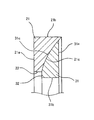
- FIG. 1 (A) shows a cross section of the main part of a sealing device 1 according to an embodiment of the present invention.
- the sealing device 1 according to the embodiment is used for a high-pressure seal portion in a hydraulic device such as an injector, and is configured as follows.
- the sealing device 1 is arranged in an annular gap between the shaft 51 and the housing 52 as two members facing each other, and the sealing fluid existing on the high pressure side H in the right direction in the figure is the low pressure side (left side in the figure). Atmosphere side) This is sealed so as not to leak to B, and is used as a seal ring that is mounted in an annular mounting groove 53 provided on the peripheral surface of the shaft 51 and is in close contact with the inner peripheral surface of the shaft hole of the housing 52.
- the first backup ring 21 disposed on the anti-sealing fluid side (low pressure side L) of the O-ring 11 and mounted in the mounting groove 53, and between the O-ring 11 and the first backup ring 21.
- the second backup ring 31 is also mounted in the mounting groove 53.
- the O-ring 11 may be a seal ring having another cross-sectional shape such as a D-ring or an X-ring.
- the O-ring 11 is formed from a rubber-like elastic body.
- the first backup ring 21 is formed of, for example, nylon resin that is harder than the second backup ring 31.
- the second backup ring 31 is formed of, for example, PTFE resin that is softer than the first backup ring 21.
- the mounting groove 53 is formed as a rectangular groove having a rectangular cross section because it is easy to process. Therefore, there is no tapered shape in the groove, and the mounting groove 53 is a combination of only a cylindrical bottom surface portion 53a and two axial side surface portions 53b.
- the first backup ring 21 has an axially perpendicular planar end surface portion 21 a on the anti-sealing fluid side (low pressure side L) that contacts the side surface portion 53 b of the mounting groove 53, and an outer peripheral side that contacts the inner peripheral surface of the shaft hole of the housing 52.
- the cylindrical surface-shaped peripheral surface portion 21b and the end surface portion 21a and the tapered surface-shaped inclined surface portion 21c intersecting the peripheral surface portion 21b are formed in a triangular cross section (right triangle shape).
- the inclined surface portion 21c has a linear cross section, and the taper direction is gradually reduced from the sealed fluid side (high pressure side H) to the anti-sealed fluid side (low pressure side L).
- the second backup ring 31 has a cylindrical end surface 31 a that is in contact with the sealing fluid side (high pressure side H) of the sealing fluid side (high-pressure side H) and an axial perpendicular plane end surface portion 31 a and a bottom surface portion 53 a of the mounting groove 53.
- the peripheral surface portion 31b and the end surface portion 31a and the tapered surface-like inclined surface portion 31c intersecting the peripheral surface portion 31b are provided and formed in a cross-sectional triangle shape (right triangle shape).
- the inclined surface portion 31c has a linear cross section, and the taper direction is gradually reduced from the sealed fluid side (high pressure side H) to the anti-sealed fluid side (low pressure side L).
- the slope portion 21c of the first backup ring 21 and the slope portion 31c of the second backup ring 31 are provided corresponding to each other, and the slope angle, slope length, maximum outer diameter size, minimum inner diameter size, and the like are equal or substantially equal. Is formed.
- the cut part 22 is provided in the corner
- the cut portion 22 is formed in an annular shape and is cut in a direction parallel to the direction of the central axis 0 of the first backup ring 21, and thus the cut portion 22 is formed in a cylindrical surface shape.
- the cut portion 22 has a diameter larger than that of the bottom surface 53 a of the mounting groove 53.
- the cut part 32 is provided in the corner
- the cut portion 32 is formed in an annular shape and is cut in a direction orthogonal to the direction of the central axis 0 of the second backup ring 31. Accordingly, the cut portion 32 is formed in a plane perpendicular to the axis.
- the seal ring 11 protrudes into the gap 54 between the shaft 51 and the housing 52.
- the second backup ring 31 is disposed between the seal ring 11 and the first backup ring 21, so that the seal ring 11 is between the first backup ring 21 and the housing 52. It is possible to prevent damage from protruding into a gap (not shown).
- the cut part 22 is provided in the corner
- the cut part 32 is provided in the corner
- the first backup ring 21 since the cut portion 22 provided in the first backup ring 21 is cut in a direction parallel to the direction of the central axis 0 of the first backup ring 21, the first backup ring 21 has a simple shape and can be processed. It is easy and easy to manufacture. Further, since the cut portion 32 provided in the second backup ring 31 is cut in a direction orthogonal to the direction of the central axis 0 of the second backup ring 31, the second backup ring 31 is also simple in shape, It is easy to process and easy to manufacture. Therefore, it is possible to provide a backup ring component that is easy to process and easy to manufacture while having the cut portions 22 and 32.
- the corner part 31e where the end face part 31a and the slope part 31c intersect in the second backup ring 31 is not provided with a cut part.
- the portion 31e is pointed and interferes with the inner peripheral surface of the shaft hole of the housing 52 when the shaft 51 and the housing 52 are eccentric from each other.
- the sealed fluid side (high pressure side H) of the corner portion 31e is a space, and a escape place is secured here. Therefore, it is not necessary to provide a cut portion in the corner portion 31e, and the protrusion of the seal ring 11 is more easily suppressed without providing the cut portion.
- the cut portion 22 provided in the first backup ring 21 preferably has an axial width y of 0.2 to 2.5 times the eccentric amount of the two members (the shaft 51 and the housing 52). is there. This is due to the following reason.
- the sealing device 1 of the present invention when used as an injector seal, the radial width d of the first backup ring 21 is 1 to 4 mm in actual size, and the first backup ring 21 is adjusted accordingly.
- the axial width w is often 1 to 2 mm.
- the angle ⁇ formed by the end face portion 21a and the slope portion 21c at this time is in the range of 14 ° to 65 °.
- the radial width of the cut portion 22 is x
- ⁇ 14 ° to 65 ° as described above
- y (0.25-2.14) .x
- the axial width y of the cut portion 22 provided in the first backup ring 21 is 0. 0 with respect to the eccentric amount of the two members.
- the size is preferably 2 to 2.5 times.
- the radial clearance c (see FIG. 1A) between the two members when the two members are positioned on the same axis is the maximum value.
- the radial clearance c between the two members is defined as the eccentric amount (maximum eccentric amount) of the two members.
- the slope portion 21 c of the first backup ring 21 is a tapered surface having a curved cross section that gradually decreases in inclination angle from the inner diameter side to the outer diameter side.
- the inclined surface portion 31c of the second backup ring 31 is similarly a tapered surface having a curved cross section with a gradually decreasing inclination angle from the inner diameter side to the outer diameter side.
- Sealing device 11 Seal ring 21 1st backup ring 21a, 31a End surface part 21b, 31b Peripheral surface part 21c, 31c Slope part 21d, 31d, 31e Corner
Landscapes
- Engineering & Computer Science (AREA)
- General Engineering & Computer Science (AREA)
- Mechanical Engineering (AREA)
- Chemical & Material Sciences (AREA)
- Combustion & Propulsion (AREA)
- Sealing Devices (AREA)
- Gasket Seals (AREA)
Priority Applications (4)
| Application Number | Priority Date | Filing Date | Title |
|---|---|---|---|
| EP15758748.6A EP3115657B1 (en) | 2014-03-06 | 2015-03-06 | Seal device |
| JP2016506563A JP6263255B2 (ja) | 2014-03-06 | 2015-03-06 | 密封装置 |
| US15/117,928 US10344865B2 (en) | 2014-03-06 | 2015-03-06 | Sealing device |
| CN201580011918.9A CN106068415B (zh) | 2014-03-06 | 2015-03-06 | 密封装置 |
Applications Claiming Priority (2)
| Application Number | Priority Date | Filing Date | Title |
|---|---|---|---|
| JP2014043578 | 2014-03-06 | ||
| JP2014-043578 | 2015-03-06 |
Publications (1)
| Publication Number | Publication Date |
|---|---|
| WO2015133595A1 true WO2015133595A1 (ja) | 2015-09-11 |
Family
ID=54055395
Family Applications (1)
| Application Number | Title | Priority Date | Filing Date |
|---|---|---|---|
| PCT/JP2015/056600 WO2015133595A1 (ja) | 2014-03-06 | 2015-03-06 | 密封装置 |
Country Status (5)
| Country | Link |
|---|---|
| US (1) | US10344865B2 (zh) |
| EP (1) | EP3115657B1 (zh) |
| JP (1) | JP6263255B2 (zh) |
| CN (1) | CN106068415B (zh) |
| WO (1) | WO2015133595A1 (zh) |
Cited By (3)
| Publication number | Priority date | Publication date | Assignee | Title |
|---|---|---|---|---|
| JP6147946B1 (ja) * | 2015-12-15 | 2017-06-14 | Nok株式会社 | 密封装置 |
| JP6442647B1 (ja) * | 2017-06-13 | 2018-12-19 | Nok株式会社 | 密封装置 |
| US10890256B2 (en) | 2018-04-16 | 2021-01-12 | Toyoda Gosei Co., Ltd. | Seal structure of high-pressure tank |
Families Citing this family (7)
| Publication number | Priority date | Publication date | Assignee | Title |
|---|---|---|---|---|
| CN106762935A (zh) * | 2017-01-22 | 2017-05-31 | 东南大学 | 摆动式液压缸内外泄露组合密封设计 |
| JP6809917B2 (ja) * | 2017-01-31 | 2021-01-06 | 株式会社バルカー | 複合シール材 |
| CN108050256B (zh) * | 2017-11-29 | 2021-03-12 | 中国飞机强度研究所 | 一种高温高压釜大间隙补偿式密封装置 |
| US11905946B2 (en) * | 2018-11-08 | 2024-02-20 | Shimadzu Corporation | Backup ring and liquid feeding pump using backup ring |
| CN109357010A (zh) * | 2018-11-21 | 2019-02-19 | 中国重型机械研究院股份公司 | 一种金属静液挤压机超超高压的一种密封结构 |
| US11137100B2 (en) * | 2020-02-06 | 2021-10-05 | Parker-Hannifin Corporation | Zero-flow fire-resistant thread-lock quick disconnect coupling |
| JP7063505B2 (ja) | 2020-05-29 | 2022-05-09 | 株式会社日新 | 移動用コンテナ構造 |
Citations (4)
| Publication number | Priority date | Publication date | Assignee | Title |
|---|---|---|---|---|
| JPH1068467A (ja) * | 1996-06-21 | 1998-03-10 | Nok Corp | シール装置 |
| JP2002161983A (ja) * | 2000-11-24 | 2002-06-07 | Nok Corp | 密封装置 |
| JP2004225778A (ja) * | 2003-01-22 | 2004-08-12 | Nok Corp | 密封装置 |
| JP2013119884A (ja) * | 2011-12-06 | 2013-06-17 | Nok Corp | 密封装置 |
Family Cites Families (9)
| Publication number | Priority date | Publication date | Assignee | Title |
|---|---|---|---|---|
| US3718338A (en) * | 1971-02-03 | 1973-02-27 | Shamban & Co W S | Sealing assembly |
| JPS562052Y2 (zh) * | 1974-11-27 | 1981-01-17 | ||
| US4268045A (en) * | 1979-04-23 | 1981-05-19 | W. S. Shamban & Co. | Seal assembly |
| US4231578A (en) * | 1979-04-23 | 1980-11-04 | W. S. Shamban & Co. | Seal assembly |
| US6502826B1 (en) * | 2000-10-30 | 2003-01-07 | Caterpillar Inc | Hydraulic cylinder piston seal |
| US7111641B2 (en) * | 2003-11-25 | 2006-09-26 | Parker-Hannifin | Zero flow fireproof quick disconnect coupling |
| CN101358652A (zh) * | 2008-09-01 | 2009-02-04 | 陈社会 | 端面旋转高压方形截面组合密封件 |
| US9109703B2 (en) * | 2010-02-11 | 2015-08-18 | Kalsi Engineering, Inc. | Hydrodynamic backup ring |
| DE102012001004A1 (de) * | 2012-01-20 | 2013-07-25 | Uhde High Pressure Technologies Gmbh | Stützringanordnung für eine Hochdruckdichtung |
-
2015
- 2015-03-06 EP EP15758748.6A patent/EP3115657B1/en active Active
- 2015-03-06 WO PCT/JP2015/056600 patent/WO2015133595A1/ja active Application Filing
- 2015-03-06 JP JP2016506563A patent/JP6263255B2/ja active Active
- 2015-03-06 CN CN201580011918.9A patent/CN106068415B/zh active Active
- 2015-03-06 US US15/117,928 patent/US10344865B2/en active Active
Patent Citations (4)
| Publication number | Priority date | Publication date | Assignee | Title |
|---|---|---|---|---|
| JPH1068467A (ja) * | 1996-06-21 | 1998-03-10 | Nok Corp | シール装置 |
| JP2002161983A (ja) * | 2000-11-24 | 2002-06-07 | Nok Corp | 密封装置 |
| JP2004225778A (ja) * | 2003-01-22 | 2004-08-12 | Nok Corp | 密封装置 |
| JP2013119884A (ja) * | 2011-12-06 | 2013-06-17 | Nok Corp | 密封装置 |
Cited By (9)
| Publication number | Priority date | Publication date | Assignee | Title |
|---|---|---|---|---|
| JP6147946B1 (ja) * | 2015-12-15 | 2017-06-14 | Nok株式会社 | 密封装置 |
| WO2017104278A1 (ja) * | 2015-12-15 | 2017-06-22 | Nok株式会社 | 密封装置 |
| CN108291650A (zh) * | 2015-12-15 | 2018-07-17 | Nok株式会社 | 密封装置 |
| EP3392533A4 (en) * | 2015-12-15 | 2018-12-19 | Nok Corporation | Sealing device |
| US11187325B2 (en) | 2015-12-15 | 2021-11-30 | Nok Corporation | Sealing device |
| JP6442647B1 (ja) * | 2017-06-13 | 2018-12-19 | Nok株式会社 | 密封装置 |
| WO2018230306A1 (ja) * | 2017-06-13 | 2018-12-20 | Nok株式会社 | 密封装置 |
| US11261970B2 (en) | 2017-06-13 | 2022-03-01 | Nok Corporation | Sealing device |
| US10890256B2 (en) | 2018-04-16 | 2021-01-12 | Toyoda Gosei Co., Ltd. | Seal structure of high-pressure tank |
Also Published As
| Publication number | Publication date |
|---|---|
| EP3115657A1 (en) | 2017-01-11 |
| JP6263255B2 (ja) | 2018-01-17 |
| CN106068415B (zh) | 2018-09-18 |
| EP3115657A4 (en) | 2017-03-29 |
| EP3115657B1 (en) | 2019-09-25 |
| US20160356381A1 (en) | 2016-12-08 |
| JPWO2015133595A1 (ja) | 2017-04-06 |
| CN106068415A (zh) | 2016-11-02 |
| US10344865B2 (en) | 2019-07-09 |
Similar Documents
| Publication | Publication Date | Title |
|---|---|---|
| JP6263255B2 (ja) | 密封装置 | |
| JP6591569B2 (ja) | ガスケット | |
| JP6147946B1 (ja) | 密封装置 | |
| JP4873173B2 (ja) | 密封装置 | |
| JP5547354B1 (ja) | 密封装置 | |
| JP2012067790A (ja) | ガスケット | |
| WO2016047352A1 (ja) | メカニカルシール | |
| KR20160132868A (ko) | 밀봉 장치 | |
| JP2007255697A (ja) | 密封装置 | |
| JP5914682B2 (ja) | 密封装置 | |
| KR102374851B1 (ko) | 축 시일 | |
| JP2007071329A (ja) | バックアップリング | |
| KR20150104177A (ko) | 밀봉구조 | |
| WO2016143397A1 (ja) | 密封装置 | |
| JP6570931B2 (ja) | 密封装置 | |
| JP4882827B2 (ja) | 配管の継手構造 | |
| CN110691930B (zh) | 密封装置 | |
| JP4758386B2 (ja) | シール装置 | |
| KR20160052355A (ko) | 조인트 | |
| JP2018004027A (ja) | 密封装置 | |
| WO2017077855A1 (ja) | フィルター付きガスケット | |
| JPWO2016147835A1 (ja) | 密封装置 | |
| WO2018116878A1 (ja) | ガスケット及び密封構造 | |
| JPWO2018163770A1 (ja) | シールリング |
Legal Events
| Date | Code | Title | Description |
|---|---|---|---|
| 121 | Ep: the epo has been informed by wipo that ep was designated in this application |
Ref document number: 15758748 Country of ref document: EP Kind code of ref document: A1 |
|
| ENP | Entry into the national phase |
Ref document number: 2016506563 Country of ref document: JP Kind code of ref document: A |
|
| REEP | Request for entry into the european phase |
Ref document number: 2015758748 Country of ref document: EP |
|
| WWE | Wipo information: entry into national phase |
Ref document number: 2015758748 Country of ref document: EP |
|
| WWE | Wipo information: entry into national phase |
Ref document number: 15117928 Country of ref document: US |
|
| NENP | Non-entry into the national phase |
Ref country code: DE |