WO2015133273A1 - 肌焼鋼鋼線 - Google Patents
肌焼鋼鋼線 Download PDFInfo
- Publication number
- WO2015133273A1 WO2015133273A1 PCT/JP2015/054408 JP2015054408W WO2015133273A1 WO 2015133273 A1 WO2015133273 A1 WO 2015133273A1 JP 2015054408 W JP2015054408 W JP 2015054408W WO 2015133273 A1 WO2015133273 A1 WO 2015133273A1
- Authority
- WO
- WIPO (PCT)
- Prior art keywords
- less
- precipitates
- steel
- content
- strength
- Prior art date
- Legal status (The legal status is an assumption and is not a legal conclusion. Google has not performed a legal analysis and makes no representation as to the accuracy of the status listed.)
- Ceased
Links
Images





Classifications
-
- C—CHEMISTRY; METALLURGY
- C22—METALLURGY; FERROUS OR NON-FERROUS ALLOYS; TREATMENT OF ALLOYS OR NON-FERROUS METALS
- C22C—ALLOYS
- C22C38/00—Ferrous alloys, e.g. steel alloys
-
- C—CHEMISTRY; METALLURGY
- C21—METALLURGY OF IRON
- C21D—MODIFYING THE PHYSICAL STRUCTURE OF FERROUS METALS; GENERAL DEVICES FOR HEAT TREATMENT OF FERROUS OR NON-FERROUS METALS OR ALLOYS; MAKING METAL MALLEABLE, e.g. BY DECARBURISATION OR TEMPERING
- C21D9/00—Heat treatment, e.g. annealing, hardening, quenching or tempering, adapted for particular articles; Furnaces therefor
- C21D9/52—Heat treatment, e.g. annealing, hardening, quenching or tempering, adapted for particular articles; Furnaces therefor for wires; for strips ; for rods of unlimited length
- C21D9/525—Heat treatment, e.g. annealing, hardening, quenching or tempering, adapted for particular articles; Furnaces therefor for wires; for strips ; for rods of unlimited length for wire, for rods
-
- C—CHEMISTRY; METALLURGY
- C22—METALLURGY; FERROUS OR NON-FERROUS ALLOYS; TREATMENT OF ALLOYS OR NON-FERROUS METALS
- C22C—ALLOYS
- C22C38/00—Ferrous alloys, e.g. steel alloys
- C22C38/001—Ferrous alloys, e.g. steel alloys containing N
-
- C—CHEMISTRY; METALLURGY
- C22—METALLURGY; FERROUS OR NON-FERROUS ALLOYS; TREATMENT OF ALLOYS OR NON-FERROUS METALS
- C22C—ALLOYS
- C22C38/00—Ferrous alloys, e.g. steel alloys
- C22C38/002—Ferrous alloys, e.g. steel alloys containing In, Mg, or other elements not provided for in one single group C22C38/001 - C22C38/60
-
- C—CHEMISTRY; METALLURGY
- C22—METALLURGY; FERROUS OR NON-FERROUS ALLOYS; TREATMENT OF ALLOYS OR NON-FERROUS METALS
- C22C—ALLOYS
- C22C38/00—Ferrous alloys, e.g. steel alloys
- C22C38/02—Ferrous alloys, e.g. steel alloys containing silicon
-
- C—CHEMISTRY; METALLURGY
- C22—METALLURGY; FERROUS OR NON-FERROUS ALLOYS; TREATMENT OF ALLOYS OR NON-FERROUS METALS
- C22C—ALLOYS
- C22C38/00—Ferrous alloys, e.g. steel alloys
- C22C38/04—Ferrous alloys, e.g. steel alloys containing manganese
-
- C—CHEMISTRY; METALLURGY
- C22—METALLURGY; FERROUS OR NON-FERROUS ALLOYS; TREATMENT OF ALLOYS OR NON-FERROUS METALS
- C22C—ALLOYS
- C22C38/00—Ferrous alloys, e.g. steel alloys
- C22C38/06—Ferrous alloys, e.g. steel alloys containing aluminium
-
- C—CHEMISTRY; METALLURGY
- C22—METALLURGY; FERROUS OR NON-FERROUS ALLOYS; TREATMENT OF ALLOYS OR NON-FERROUS METALS
- C22C—ALLOYS
- C22C38/00—Ferrous alloys, e.g. steel alloys
- C22C38/18—Ferrous alloys, e.g. steel alloys containing chromium
- C22C38/22—Ferrous alloys, e.g. steel alloys containing chromium with molybdenum or tungsten
-
- C—CHEMISTRY; METALLURGY
- C22—METALLURGY; FERROUS OR NON-FERROUS ALLOYS; TREATMENT OF ALLOYS OR NON-FERROUS METALS
- C22C—ALLOYS
- C22C38/00—Ferrous alloys, e.g. steel alloys
- C22C38/18—Ferrous alloys, e.g. steel alloys containing chromium
- C22C38/26—Ferrous alloys, e.g. steel alloys containing chromium with niobium or tantalum
-
- C—CHEMISTRY; METALLURGY
- C22—METALLURGY; FERROUS OR NON-FERROUS ALLOYS; TREATMENT OF ALLOYS OR NON-FERROUS METALS
- C22C—ALLOYS
- C22C38/00—Ferrous alloys, e.g. steel alloys
- C22C38/18—Ferrous alloys, e.g. steel alloys containing chromium
- C22C38/28—Ferrous alloys, e.g. steel alloys containing chromium with titanium or zirconium
-
- C—CHEMISTRY; METALLURGY
- C22—METALLURGY; FERROUS OR NON-FERROUS ALLOYS; TREATMENT OF ALLOYS OR NON-FERROUS METALS
- C22C—ALLOYS
- C22C38/00—Ferrous alloys, e.g. steel alloys
- C22C38/18—Ferrous alloys, e.g. steel alloys containing chromium
- C22C38/40—Ferrous alloys, e.g. steel alloys containing chromium with nickel
- C22C38/42—Ferrous alloys, e.g. steel alloys containing chromium with nickel with copper
-
- C—CHEMISTRY; METALLURGY
- C22—METALLURGY; FERROUS OR NON-FERROUS ALLOYS; TREATMENT OF ALLOYS OR NON-FERROUS METALS
- C22C—ALLOYS
- C22C38/00—Ferrous alloys, e.g. steel alloys
- C22C38/18—Ferrous alloys, e.g. steel alloys containing chromium
- C22C38/40—Ferrous alloys, e.g. steel alloys containing chromium with nickel
- C22C38/44—Ferrous alloys, e.g. steel alloys containing chromium with nickel with molybdenum or tungsten
-
- C—CHEMISTRY; METALLURGY
- C22—METALLURGY; FERROUS OR NON-FERROUS ALLOYS; TREATMENT OF ALLOYS OR NON-FERROUS METALS
- C22C—ALLOYS
- C22C38/00—Ferrous alloys, e.g. steel alloys
- C22C38/18—Ferrous alloys, e.g. steel alloys containing chromium
- C22C38/40—Ferrous alloys, e.g. steel alloys containing chromium with nickel
- C22C38/46—Ferrous alloys, e.g. steel alloys containing chromium with nickel with vanadium
-
- C—CHEMISTRY; METALLURGY
- C22—METALLURGY; FERROUS OR NON-FERROUS ALLOYS; TREATMENT OF ALLOYS OR NON-FERROUS METALS
- C22C—ALLOYS
- C22C38/00—Ferrous alloys, e.g. steel alloys
- C22C38/18—Ferrous alloys, e.g. steel alloys containing chromium
- C22C38/40—Ferrous alloys, e.g. steel alloys containing chromium with nickel
- C22C38/48—Ferrous alloys, e.g. steel alloys containing chromium with nickel with niobium or tantalum
-
- C—CHEMISTRY; METALLURGY
- C22—METALLURGY; FERROUS OR NON-FERROUS ALLOYS; TREATMENT OF ALLOYS OR NON-FERROUS METALS
- C22C—ALLOYS
- C22C38/00—Ferrous alloys, e.g. steel alloys
- C22C38/18—Ferrous alloys, e.g. steel alloys containing chromium
- C22C38/40—Ferrous alloys, e.g. steel alloys containing chromium with nickel
- C22C38/50—Ferrous alloys, e.g. steel alloys containing chromium with nickel with titanium or zirconium
-
- C—CHEMISTRY; METALLURGY
- C23—COATING METALLIC MATERIAL; COATING MATERIAL WITH METALLIC MATERIAL; CHEMICAL SURFACE TREATMENT; DIFFUSION TREATMENT OF METALLIC MATERIAL; COATING BY VACUUM EVAPORATION, BY SPUTTERING, BY ION IMPLANTATION OR BY CHEMICAL VAPOUR DEPOSITION, IN GENERAL; INHIBITING CORROSION OF METALLIC MATERIAL OR INCRUSTATION IN GENERAL
- C23C—COATING METALLIC MATERIAL; COATING MATERIAL WITH METALLIC MATERIAL; SURFACE TREATMENT OF METALLIC MATERIAL BY DIFFUSION INTO THE SURFACE, BY CHEMICAL CONVERSION OR SUBSTITUTION; COATING BY VACUUM EVAPORATION, BY SPUTTERING, BY ION IMPLANTATION OR BY CHEMICAL VAPOUR DEPOSITION, IN GENERAL
- C23C8/00—Solid state diffusion of only non-metal elements into metallic material surfaces; Chemical surface treatment of metallic material by reaction of the surface with a reactive gas, leaving reaction products of surface material in the coating, e.g. conversion coatings, passivation of metals
- C23C8/06—Solid state diffusion of only non-metal elements into metallic material surfaces; Chemical surface treatment of metallic material by reaction of the surface with a reactive gas, leaving reaction products of surface material in the coating, e.g. conversion coatings, passivation of metals using gases
- C23C8/08—Solid state diffusion of only non-metal elements into metallic material surfaces; Chemical surface treatment of metallic material by reaction of the surface with a reactive gas, leaving reaction products of surface material in the coating, e.g. conversion coatings, passivation of metals using gases only one element being applied
- C23C8/20—Carburising
- C23C8/22—Carburising of ferrous surfaces
-
- C—CHEMISTRY; METALLURGY
- C21—METALLURGY OF IRON
- C21D—MODIFYING THE PHYSICAL STRUCTURE OF FERROUS METALS; GENERAL DEVICES FOR HEAT TREATMENT OF FERROUS OR NON-FERROUS METALS OR ALLOYS; MAKING METAL MALLEABLE, e.g. BY DECARBURISATION OR TEMPERING
- C21D1/00—General methods or devices for heat treatment, e.g. annealing, hardening, quenching or tempering
- C21D1/06—Surface hardening
-
- C—CHEMISTRY; METALLURGY
- C21—METALLURGY OF IRON
- C21D—MODIFYING THE PHYSICAL STRUCTURE OF FERROUS METALS; GENERAL DEVICES FOR HEAT TREATMENT OF FERROUS OR NON-FERROUS METALS OR ALLOYS; MAKING METAL MALLEABLE, e.g. BY DECARBURISATION OR TEMPERING
- C21D2211/00—Microstructure comprising significant phases
- C21D2211/004—Dispersions; Precipitations
-
- C—CHEMISTRY; METALLURGY
- C21—METALLURGY OF IRON
- C21D—MODIFYING THE PHYSICAL STRUCTURE OF FERROUS METALS; GENERAL DEVICES FOR HEAT TREATMENT OF FERROUS OR NON-FERROUS METALS OR ALLOYS; MAKING METAL MALLEABLE, e.g. BY DECARBURISATION OR TEMPERING
- C21D8/00—Modifying the physical properties of ferrous metals or ferrous alloys by deformation combined with, or followed by, heat treatment
- C21D8/06—Modifying the physical properties of ferrous metals or ferrous alloys by deformation combined with, or followed by, heat treatment during manufacturing of rods or wires
Definitions
- the present invention relates to a case-hardened steel wire.
- automotive parts especially gears and shafts used in transmissions, are generally tempered after surface hardening treatment such as carburizing and quenching. It is manufactured by applying.
- the above-mentioned “carburizing and quenching” generally uses low-carbon “skin-hardened steel” as raw material steel (dough steel), and infiltrates and diffuses C in a high temperature austenite region of Ac 3 points or more After that, it is a quenching process.
- carburized parts such as the above gears require higher bending fatigue strength and higher pitching strength than ever before.
- the “carburized part” will be described below by representing “the gear”.
- the gear can ensure high bending fatigue strength and high pitching strength.
- alloy elements such as Ni, Cr and Mo
- Ni and Mo are both important elements that increase the depth of the carburized layer and the hardness of the core (fabric), and are elements that improve the temper softening resistance.
- both Ni and Mo are non-oxidizing elements, they have the effect of improving the hardenability of the carburized layer without increasing the depth of the grain boundary oxide layer formed on the surface during gas carburizing. ing.
- nickel chrome molybdenum steel such as SNCM220H defined in JIS G 4052 (2008) or “chromium molybdenum steel” such as SCM420H is used as “hardened steel” as a material of gears. Many.
- Patent Literature 1 and Patent Literature 2 propose “hardened steel” and “gear steel with excellent surface fatigue strength”, respectively.
- Patent Document 2 by mass, C: 0.10 to 0.30%, Si: 0.35% or less, Mn: 0.8% or less, Cr: 1.5 to 2.5% And, if necessary, further comprising at least one selected from Ni: 3.0% or less, Mo: 1.0% or less, and Cu: 1.0% or less, comprising the balance Fe and inevitable impurities, and
- the amount of Si + Cr is in the range of 1.8 to 2.8%, and further has a surface hardened layer by carbonitriding or quenching and tempering after carbonitriding, and the amount of C + N from the surface to 0.1 mm is 1.0 to
- a “steel for gears having excellent surface fatigue strength” characterized by being in the range of 2.0% is disclosed.
- Patent Document 1 secures coarsening resistance during surface hardening treatment by adjusting the amounts of Al, Nb and N in the steel and actively regulates the upper limit values of S and O Although it has a technical idea of ensuring cold workability by doing so, no consideration is given to the form of precipitates. For this reason, the technique of patent document 1 cannot necessarily ensure high pitching strength to components, such as a gearwheel and a shaft.
- Patent Document 2 has a Si + Cr content in the range of 1.8 to 2.8%, and further has a hardened surface layer by carbonitriding or quenching and tempering after carbonitriding, and is 0.
- the surface fatigue strength is excellent by setting the C + N amount up to 1 mm in the range of 1.0 to 2.0%, no consideration is given to cold workability. For this reason, it is not always possible to ensure both high pitching strength and cold workability in parts such as gears and shafts.
- An object of the present invention is a case-hardened steel having a low component cost, excellent bending fatigue strength, pitching strength, cold workability and coarse grain resistance, and suitable for use as a material for carburized parts such as gears and shafts.
- the object of the present invention is to provide good workability in cold working such as cold forging, and to prevent the inclusion of expensive elements Ni and Mo, or their content as much as possible.
- An object of the present invention is to provide a case-hardened steel wire capable of ensuring pitching strength and coarsening resistance.
- the term “steel wire” refers to a steel material that has been hot rolled or forged into a rod shape, that is, “steel”, “wire”, or “burn-in coil” after spheroidizing and annealing, The shape is finished by drawing, drawing, etc., and the shape includes a so-called “bar” shape in addition to a coil shape.
- the present inventors have made various studies in order to solve the above-described problems. As a result, first, the following findings (a) to (d) were obtained.
- Coarse MnS is the starting point of cracking during cold forging. For this reason, it is necessary to reduce coarse MnS as much as possible in order to suppress cracking during cold forging.
- the present inventors further ensured the hardenability corresponding to the Ni and Mo content reduction, and also optimized the Mn and S contents and their balance to suppress the formation of coarse MnS.
- Various studies were conducted. As a result, the following findings (e) to (i) were obtained.
- type B and type D large hard inclusions measured according to ASTM-E45-13 method A, that is, mainly Al It is necessary to suppress type B inclusions, which are 2 O 3 inclusions, and type D inclusions, which are mainly TiN inclusions, having a large thickness. This is because the large hard inclusions of type B and type D described above serve as starting points for fatigue failure.
- the content of Ti and O (oxygen) among impurities is particularly 0.005% or less and 0.0020%, respectively. It is necessary to control the following.
- secondary refining is repeated or during continuous casting. It is desirable to perform electromagnetic stirring.
- the total number of Al precipitates and Nb precipitates having a circle-equivalent diameter of 100 nm or more at a position of 1 ⁇ 2 radius from the surface of the steel wire is 100 or less in 100 ⁇ m 2 . If the total number of Al precipitates and Nb precipitates having an equivalent circle diameter of 5 nm or more and less than 100 nm is 100 or more in 25 ⁇ m 2 , coarsening during carburizing and quenching is suppressed. be able to.
- the present invention has been completed based on the above findings, and the gist thereof is the case-hardened steel wire shown below.
- the chemical composition is mass%, C: 0.10 to 0.24%, Si: 0.16 to 0.35%, Mn: 0.40 to 1.00%, S: 0.005 to 0.050%, Cr: 1.65 to 1.90%, Al: 0.015 to 0.060%, Nb: 0.005 to 0.060%, N: 0.0130 to 0.0250%, Cu: 0 to 0.20%, Ni: 0 to 0.20%, V: 0 to 0.20%, Ca: 0 to 0.0050%, Balance: Fe and impurities,
- the values of Fn1, Fn2 and Fn3 represented by the following formulas (i), (ii) and (iii) are 15 ⁇ Fn1 ⁇ 150, 0.75 ⁇ Fn2 ⁇ 1.40 and 0.30, respectively.
- the chemical composition is mass%, The case-hardened steel wire according to (1) above, which contains one or more selected from Cu: 0.05 to 0.20% and Ni: 0.05 to 0.20%.
- the chemical composition is mass%, The case-hardened steel wire according to any one of (1) to (3), containing Ca: 0.0003 to 0.0050%.
- the case-hardened steel wire of the present invention is excellent in cold workability and has low component cost, and the carburized parts made from this case-hardened steel wire are made of “chrome molybdenum” defined in JIS G 4052 (2008). It has bending fatigue strength, pitting strength, and coarse grain resistance, which are the same as or higher than those of carburized parts made of SCM420H of “steel”. For this reason, the case-hardened steel wire of the present invention is suitable for use as a material for carburized parts such as gears and shafts that require high bending fatigue strength and high wear resistance in order to reduce weight and torque. .
- FIG. 5 is a front view when a coarse roller pitching large roller test piece is halved by a center line, and (b) is a cross-sectional view at the center line.
- the unit of the dimension in the figure is “mm”.
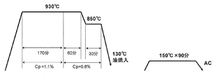
- FIG. 6 is a diagram showing a heat pattern of “carburization quenching-tempering” performed on the test piece shown in FIG. 5 in Examples. It is a figure which shows the finishing shape of the Ono type
- the unit of the dimension in the figure is “mm”.
- FIG. 10 It is a figure which shows the finishing shape of the roller pitching small roller test piece used in the Example.
- the unit of the dimension in the figure is “mm”.
- FIG. 10 (a) is a front view when a roller pitching large roller test piece is halved by a center line, and (b) is a cross-sectional view at the center line.
- the unit of the dimension in the figure is “mm”.
- C 0.10 to 0.24%
- C is an essential element for ensuring the strength of carburized parts such as gears and shafts, and a content of 0.10% or more is necessary.
- the content of C is too large, the hardness increases and machinability is lowered.
- the content exceeds 0.24% the machinability is significantly lowered due to the increase in hardness.
- the C content is 0.10 to 0.24%.
- it is preferable that content of C is 0.13% or more, and it is preferable that it is 0.23% or less.
- Si 0.16-0.35%
- Si has an action of improving hardenability and a deoxidizing action. Further, Si has resistance to temper softening and has an effect of preventing the surface from being softened under the condition that the sliding surface such as a gear is exposed to a high temperature. In order to obtain these effects, it is necessary to contain 0.16% or more of Si.
- Si is an oxidizing element, when its content increases, Si is selectively oxidized by a small amount of H 2 O or CO 2 contained in the carburizing gas, and Si oxide is generated on the steel surface. Therefore, the depths of the grain boundary oxide layer and the incompletely quenched layer, which are carburized abnormal layers, are increased.
- the Si content is set to 0.16 to 0.35%.
- the Si content is preferably 0.18% or more, and preferably 0.30% or less.
- the Si content is within the above range, and Fn2 and Fn3 represented by the above formulas (ii) and (iii) are 0.75 ⁇ Fn2 ⁇ 1.40 and 0.30 ⁇ Fn3 ⁇ 0. It is also necessary to satisfy 65.
- Mn 0.40 to 1.00%
- Mn has an action of improving hardenability and a deoxidizing action. Mn also has the effect of suppressing temper softening. In order to obtain these effects, a Mn content of 0.40% or more is necessary. However, if the Mn content increases, the hardness increases and the machinability decreases. In particular, when the content exceeds 1.00%, the machinability is significantly decreased due to the increase in hardness. Become.
- Mn is an oxidizing element, so if its content increases, Mn oxide is generated on the steel surface, so the grain boundary oxide layer and incomplete quenching, which are carburizing abnormal layers. The depth of the layer increases.
- the Mn content is set to 0.40 to 1.00%.
- the Mn content is preferably 0.50% or more, and preferably 0.95% or less.
- the content of Mn needs to satisfy 15 ⁇ Fn1 ⁇ 150 and 0.75 ⁇ Fn2 ⁇ 1.40 for Fn1 and Fn2 represented by the above formulas (i) and (ii) There is.
- S 0.005 to 0.050% S combines with Mn to form MnS and has the effect of improving machinability. In order to obtain this effect, it is necessary to contain 0.005% or more of S. However, if the S content exceeds 0.050%, coarse MnS is formed, and cold forgeability and bending fatigue strength are reduced. Therefore, the S content is set to 0.005 to 0.050%.
- the content of S is preferably 0.010% or more, and preferably 0.040% or less.
- Fn1 represented by the above formula (i) it is necessary for Fn1 represented by the above formula (i) to satisfy 15 ⁇ Fn1 ⁇ 150 within the above range of the S content.
- Cr 1.65 to 1.90%
- Cr has the effect of improving hardenability.
- Cr has resistance to temper softening and has an effect of preventing the surface from being softened under the condition that the sliding surface of the carburized parts such as gears and shafts is exposed to high temperature.
- a Cr content of 1.65% or more is required.
- the Cr content increases, the hardness increases and machinability is reduced.
- the content exceeds 1.90%, the machinability is significantly reduced as the hardness increases. Become.
- Cr is an oxidizing element, so if its content increases, Cr oxide is generated on the steel surface, so the grain boundary oxidation layer, which is an abnormal carburizing layer, and incomplete The depth of the hardened layer increases. And when the depth of the carburizing abnormal layer is increased, the bending fatigue strength and the pitching strength are reduced. In particular, when the Cr content exceeds 1.90%, the bending fatigue strength due to the increase in the depth of the carburizing abnormal layer and The decrease in pitching strength becomes significant. Therefore, the Cr content is 1.65 to 1.90%. The content of Cr is preferably 1.85% or less.
- the Cr content is within the above range, and Fn2 and Fn3 represented by the above formulas (ii) and (iii) are 0.75 ⁇ Fn2 ⁇ 1.40 and 0.30 ⁇ Fn3 ⁇ 0. It is necessary to satisfy 65.
- Al 0.015 to 0.060%
- Al has a deoxidizing action. Moreover, Al also has the effect
- the Al content is less than 0.015%, it is difficult to obtain the above effect.
- the Al content is excessive, the machinability is lowered due to the formation of hard and coarse Al 2 O 3 , and the bending fatigue strength is also lowered. In particular, when the Al content exceeds 0.060%, the machinability and bending fatigue strength are significantly reduced. Therefore, the Al content is set to 0.015 to 0.060%.
- the Al content is preferably 0.020% or more, and preferably 0.055% or less.
- Nb 0.005 to 0.060%
- Nb combines with C and N to form fine carbides, nitrides or carbonitrides to refine crystal grains, and has the effect of improving bending fatigue strength and pitching strength. To obtain this effect, an Nb content of 0.005% or more is necessary.
- the Nb content is set to 0.005 to 0.060%.
- the Nb content is preferably 0.015% or more, and preferably 0.050% or less.
- N 0.0130 to 0.0250%
- N has the effect of making the crystal grains finer by forming nitrides and improving the bending fatigue strength. In order to acquire this effect, it is necessary to contain N 0.0130% or more. However, when the content of N is excessive, coarse nitrides are formed and the toughness is reduced. In particular, when the content exceeds 0.0250%, the toughness and the cold forgeability are reduced. It becomes remarkable. In addition, type D large inclusions are easily generated, and bending fatigue strength and pitching strength are reduced. Therefore, the N content is 0.0130 to 0.0250%. The N content is preferably 0.0200% or less.
- the case-hardened steel wire according to the present invention consists of the above-described elements from C to N, the balance being Fe and impurities, and further satisfying the conditions for Fn1, Fn2 and Fn3 described later, P in the impurities, It has a chemical composition in which the contents of Ti, Mo and O (oxygen) are limited to the ranges described below.
- impurities in the “Fe and impurities” as the balance are those that are mixed due to various factors in the manufacturing process, including raw materials such as ore or scrap, when industrially manufacturing steel materials. Point to.
- Fn1 is smaller than 15, the content of S becomes excessive, and generation of coarse MnS is inevitable.
- Fn1 is larger than 150, the Mn content is excessive and coarse MnS is generated in the central segregation part. Therefore, in any case, the bending fatigue strength is reduced, and cracks during cold forging are difficult to avoid. Therefore, for Fn1, 15 ⁇ Fn1 ⁇ 150.
- Fn1 is preferably 30 or more, and preferably 100 or less.
- Fn2 0.75 to 1.40
- the grain boundary oxide layer and the incompletely hardened layer are carburized abnormal layers. It is necessary to reduce the depth.
- the content of Cr, Si and Mn among the oxidizing elements is set in the above range, and the content balance of these elements is expressed by the following formula (ii).
- Fn2 needs to be in the range of 0.75 to 1.40.
- Fn2 Cr / (Si + 2Mn) (ii)
- the element symbol in the said formula represents content in the mass% of the element.
- Fn2 is smaller than 0.75 and larger than 1.40, the depth of the carburized abnormal layer is increased, so that the bending fatigue strength and the pitching strength are lowered. Therefore, suppose that 0.75 ⁇ Fn2 ⁇ 1.40 for Fn2.
- Fn2 is preferably 0.80 or more, and preferably 1.30 or less.
- Fn3 0.30 to 0.65
- high-temperature strength that is, temper softening resistance
- the content of Si and Cr must be within the above range
- Fn3 represented by the following formula (iii) must be within the range of 0.30 to 0.65.
- Fn3 Si ⁇ Cr (iii)
- the element symbol in the said formula represents content in the mass% of the element.
- Fn3 is less than 0.30, the temper softening resistance is low, and a desired pitching strength cannot be obtained.
- Fn3 is larger than 0.65, the bending fatigue strength and the pitching strength are significantly reduced due to the increased depth of the carburized abnormal layer. Therefore, it is assumed that 0.30 ⁇ Fn3 ⁇ 0.65 for Fn3.
- Fn3 is preferably 0.60 or less.
- the contents of P, Ti, Mo and O in the impurities are P: 0.020% or less, Ti: 0.005% or less, Mo: 0.03% or less, and O, respectively. : It is necessary to limit to 0.0020% or less.
- P 0.020% or less
- P is an impurity contained in the steel and segregates at the grain boundaries to embrittle the steel.
- the content exceeds 0.020%, the degree of embrittlement becomes significant. Therefore, the P content is 0.020% or less.
- the P content is preferably 0.015% or less.
- Ti 0.005% or less Since Ti has a high affinity with N, it combines with N in steel to form TiN, which is a hard and coarse type D non-metallic inclusion, resulting in bending fatigue strength and pitching. The strength is lowered and the machinability is also lowered. Therefore, the Ti content is set to 0.005% or less.
- Mo 0.03% or less Mo is an expensive element, and if contained, the component cost increases. Further, when the content of Mo in the impurities varies, the mechanical properties are not stable. Therefore, the Mo content is set to 0.03% or less.
- O 0.0020% or less
- O oxygen
- Si silicon
- Al aluminum
- the like in steel to generate an oxide.
- the oxides in particular, Al 2 O 3 which is a non-metallic inclusion of type B is hard, so that machinability is lowered and bending fatigue strength and pitching strength are also lowered. Therefore, the content of O is set to 0.0020% or less.
- the O content is preferably 0.0015% or less.
- the case-hardened steel wire according to the present invention may contain one or more elements selected from the elements shown in the following ⁇ 1> to ⁇ 3>.
- Cu 0 to 0.20% Since Cu has the effect
- the amount of Cu is preferably 0.05% or more, and more preferably 0.07% or more.
- Ni 0 to 0.20%
- Ni has an effect of improving hardenability. Furthermore, since Ni has a function of improving toughness and is a non-oxidizing element, the steel surface can be toughened without increasing the depth of the grain boundary oxide layer during carburizing. For this reason, in order to acquire these effects, you may contain Ni.
- Ni is an expensive element, and excessive addition leads to an increase in component cost. In particular, when the Ni content exceeds 0.20%, the cost increase becomes large. Therefore, the amount of Ni in the case of inclusion is set to 0.20% or less.
- the amount of Ni is preferably 0.05% or more, and more preferably 0.07% or more.
- the total amount in the case where the two kinds of Cu and Ni are combined and contained is 0.30% or less.
- V has the effect of combining with C and N to form fine carbides, nitrides and carbonitrides to refine crystal grains and improve bending fatigue strength and pitching strength.
- V may be contained.
- the V content is excessive, the hot ductility is deteriorated.
- the V content exceeds 0.20%, the hot ductility is significantly reduced, such as hot rolling and hot forging. Surface scratches are likely to occur during hot working. Therefore, the V content in the case of inclusion is 0.20% or less.
- the amount of V is preferably 0.10% or less.
- the amount of V is preferably 0.05% or more, and more preferably 0.07% or more.
- Ca 0 to 0.0050%
- Ca has the effect
- excessive Ca addition leads to an increase in the component cost.
- the Ca content exceeds 0.0050%, the machinability improving effect is saturated, so the cost is increased and the economy is impaired.
- the Ca content in the case of inclusion is 0.0050% or less.
- the amount of Ca is preferably 0.0030% or less.
- the amount of Ca is preferably 0.0003% or more, and more preferably 0.0005% or more.
- a slab or steel ingot obtained by melting a case-hardened steel having the chemical composition described in the above section (A) and casting it is heated for 30 to 1200 minutes at a temperature of 1150 to 1350 ° C. Bulk rolling into steel slabs.
- the steel slab is heated to a temperature of 1150 ° C. or lower, preferably 900 to 1150 ° C. for 15 to 120 minutes, and then the finishing temperature is set to 800 ° C. or higher.
- the steel plate is cooled by cooling at a cooling rate in the temperature range of 800 to 500 ° C.
- the hardness at a position of 50 ⁇ m from the more preferable surface is 230 or less in HV.
- the minimum of the hardness of a 50 micrometer position from the surface of the case hardening steel wire which concerns on this invention will be about 130 in HV.
- the case-hardened steel having the chemical composition described in the section (A) is melted in a vacuum melting furnace or in a converter. It is preferable to repeat secondary refining or to perform electromagnetic stirring during continuous casting.
- the spheroidizing annealing method in producing the case-hardened steel wire according to the present invention is not particularly specified, and for example, an appropriate method is selected from a long-time heating method, a repeated heating cooling method, a slow cooling method, and an isothermal transformation method. do it. Furthermore, methods such as cold drawing and drawing are not particularly specified, and may be performed by a normal method.
- (C) Precipitate at half the radius from the surface In the case-hardened steel wire according to the present invention, the total number of Al precipitates and Nb precipitates having a circle-equivalent diameter of 100 nm or more at a position of 1 ⁇ 2 radius from the surface is 100 in 100 ⁇ m 2. The total number of Al precipitates and Nb precipitates having an equivalent circle diameter of 5 nm or more and less than 100 nm must be 100 or more in 25 ⁇ m 2 .
- a fine precipitate having a pinning effect specifically, a circle
- the number of precipitates having an equivalent diameter of 5 nm or more and less than 100 nm is reduced, and coarse precipitates adversely affect the pitching strength.
- the total number of Al precipitates and Nb precipitates having an equivalent circle diameter of 100 nm or more is 100 per 100 ⁇ m 2 as the coarse precipitates. If it exceeds, not only the pinning effect can be secured, but also the pitching strength is lowered.
- the total number of Al precipitates and Nb precipitates having an equivalent circle diameter of 100 nm or more is preferably 80 or less in 100 ⁇ m 2 , and is very preferably 0.
- the total number of Al precipitates and Nb precipitates having an equivalent circle diameter of 5 nm or more and less than 100 nm is 25 ⁇ m 2 as the fine precipitates.
- the number is 100 or more, the pinning effect is exerted, and coarsening during carburizing and quenching can be suppressed, and a good pitching strength can be secured stably.
- the circle equivalent diameters of the Al precipitates and Nb precipitates as fine precipitates at a position 1/2 the radius from the surface are preferably 10 nm or more, and preferably 80 nm or less.
- the total number of Al precipitates and Nb precipitates having an equivalent circle diameter of 5 nm or more and less than 100 nm at the above position is preferably 110 or more in 25 ⁇ m 2 , and the larger the better. .
- Al precipitate specifically refers to “AlN”
- Nb precipitate specifically refers to “NbC, NbN and Nb (CN)”.
- the precipitate at the position of radius 1 ⁇ 2 from the surface is the production method described in the section (B), that is, the chemical composition described in the section (A).
- a slab or steel ingot obtained by melting and casting a case-hardened steel is rolled into a steel slab, and the steel slab is hot-rolled and manufactured by adjusting the cooling conditions after the hot rolling is completed.
- This can be obtained by spheroidizing annealing using a steel bar, a wire rod, etc., and then further drawing and drawing in a cold state.
- Al and Nb are dissolved in the steel by heating at a temperature of 1150 to 1350 ° C. for 30 to 1200 minutes during the batch rolling described in the section (B), and also described in the section (B). This is because the Ostwald growth of precipitates is unlikely to occur in hot rolling of steel slabs.
- Steels 1 to 22 having the chemical composition shown in Table 1 were melted by a converter or a vacuum melting furnace to produce a slab or an ingot.
- steels 1 to 10 and 18 to 20 in Table 1 are steels whose chemical compositions are within the range defined by the present invention.
- steels 12 and 13 are steels in which the content of individual elements is within the range defined by the present invention, but Fn1 is outside the conditions defined by the present invention, and steels 14 and 15 are individual elements. Although the content of is within the range defined by the present invention, Fn2 is a steel that deviates from the conditions defined by the present invention.
- Steels 16 and 17 are steels in which Fn3 deviates from the conditions defined in the present invention, although the content of each element is within the range defined in the present invention.
- the steels 21 and 22 are steels in which the content of at least one element deviates from the conditions defined in the present invention.
- Steel 11 is steel corresponding to SCM420H specified in JIS G 4052 (2008), and is out of the conditions specified in the present invention.
- steel bars having a diameter of 35 mm were produced from the ingot by the following steps [2] and [3].
- each ingot was held at the temperature and time shown in Table 2, and then hot forged to produce a steel bar having a diameter of 45 mm.
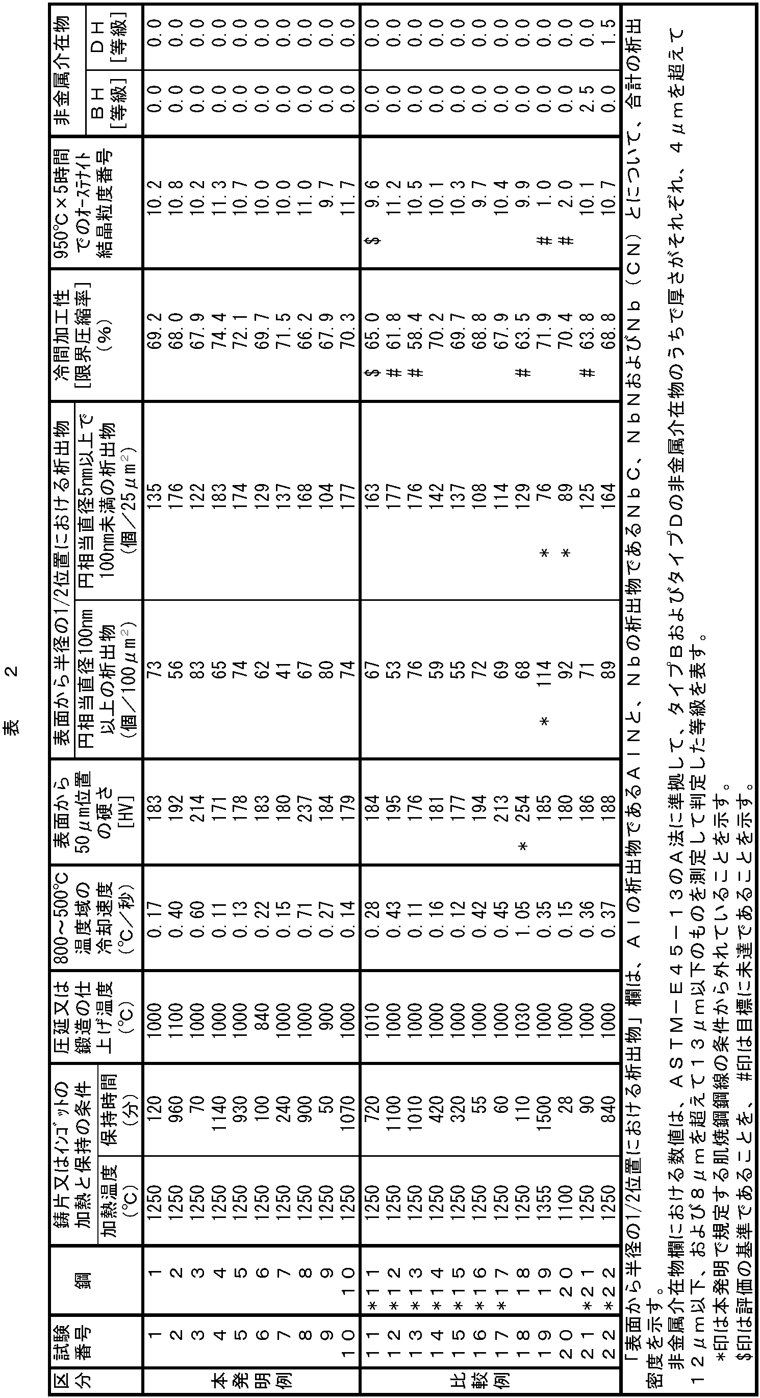
- Table 2 shows the forging finishing temperature of the steel bar and the cooling rate in the temperature range of 800 to 500 ° C.
- Spheroidizing annealing The steel bar and the burn-in coil having a diameter of 35 mm were subjected to spheroidizing annealing that was held at 760 ° C. for 10 hours, gradually cooled to 650 ° C. over 9 hours, and then allowed to cool.
- each steel wire having a diameter of 33 mm is longitudinally cut from the surface at a half radius position, that is, parallel to the length direction, and an extracted replica sample is prepared from the cut surface by a general method. did.
- test pieces were prepared from the remaining steel wires having a diameter of 33 mm obtained as described above by the steps [6] to [8] below. Furthermore, the test piece shown in [6] was cut out from a steel bar of SCM420H specified in JIS G 4052 (2008) having a diameter of 140 mm prepared separately.
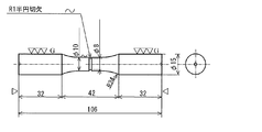
- Machining (roughing or finishing): From the center of each steel wire having a diameter of 33 mm, a coarse notched Ono type rotating bending fatigue test piece shown in FIG. 1, parallel to the rolling direction or the forging axis, the coarse shape roller pitching small roller shown in FIG. A test piece, a test piece for evaluation of cold workability shown in FIG. 3, and a test piece for evaluation of coarse grain resistance shown in FIG. 4 were cut out.
- a steel bar having a diameter of 140 mm was manufactured by rolling the slab of SCM420H defined in JIS G 4052 (2008) melted using a converter, and this was held at 920 ° C. for 2 hours. Later, the coarse roller pitching large roller test piece shown in FIG. 5 was cut out from what was allowed to cool in the atmosphere and normalized.
- the unit of the dimension in each of the above cut-out test pieces shown in FIGS. 1 to 5 is “mm”, and the three types of inverted triangle symbols in the figure are the description table 1 of JIS B 0601 (1982). Is a “finishing symbol” indicating the surface roughness described in 1.
- G attached to the finish symbol means an abbreviation of a processing method indicating “grinding” defined in JIS B 0122 (1978).
- each steel wire having a diameter of 33 mm was subjected to a non-metallic inclusion investigation after water quenching. Details of the survey method will be described later.
- notched rotary bending fatigue test piece and roller pitching small roller test piece were subjected to the above treatment in a suspended state by passing a wire through a hole processed for suspension.
- Cp in FIGS. 6 and 7 represents the carbon potential.
- 130 ° C. oil quenching indicates quenching in oil at an oil temperature of 130 ° C.
- AC indicates air cooling.
- test piece was thrown into the quenching oil so that it could be uniformly quenched.
- the unit of dimension in each of the above-mentioned test pieces shown in FIGS. 8 to 10 is “mm”, and the two types of inverted triangle symbols in the above figures are shown in the explanation table 1 of JIS B 0601 (1982). It is a “finish symbol” indicating the surface roughness described.
- G attached to the finish symbol means an abbreviation of a processing method indicating “grinding” defined in JIS B 0122 (1978).
- ⁇ (wave dash) in FIG. 8 is a “waveform symbol”, which means that it is a dough, that is, it remains on the surface subjected to the carburizing and quenching treatment of [7].
- Hardness measurement at 50 ⁇ m position from the surface The HV (Vickers hardness) at 10 points 50 ⁇ m from the surface of the test piece for mirror-polished hardness measurement is in accordance with “Vickers hardness test-test method” described in JIS Z 2244 (2009). Then, the test force was 0.98N and measured with a Vickers hardness tester, and the arithmetic average value of the 10 points was set to a hardness of 50 ⁇ m position from the surface.
- ⁇ 2 Investigation of precipitates at a half radius position from the surface:
- the extracted replica sample produced by the above general method is used using a transmission electron microscope (hereinafter referred to as “TEM”) equipped with an energy dispersive X-ray analyzer (hereinafter referred to as “EDX”).
- TEM transmission electron microscope
- EDX energy dispersive X-ray analyzer
- the total precipitation density was investigated for AlN, which is an Al precipitate, and NbC, NbN, and Nb (CN), which are Nb precipitates.
- the content and shape of Al and Nb in the precipitates were confirmed by elemental analysis by EDX, 20 fields of view were observed with a TEM magnification of 30000, and the Al precipitates and Nb precipitates were analyzed by image analysis. The areas were calculated, converted into circle areas, and the equivalent circle diameter was determined.
- the total number of Al precipitates and Nb precipitates having an equivalent circle diameter of 100 nm or more was counted and converted into the number per 100 ⁇ m 2 area.
- the total number of Al precipitates and Nb precipitates having an equivalent circle diameter of 5 nm or more and less than 100 nm was counted and converted to the number per area of 25 ⁇ m 2 .
- ⁇ 4 Investigation of anti-coagulation characteristics: The test piece of FIG. 4 produced as described in [6] above was compressed by 70% in height with a hydraulic press at room temperature and with the length in the length direction. Thereafter, in order to simulate heating by carburization, the test piece was heated to 950 ° C. and held for 5 hours, and then water quenching was performed, and each test piece was longitudinally cut to include the central axis, that is, in the height direction. Was cut into parallel to the substrate, embedded in resin so that the cut surface was the test surface, and polished so that the surface had a mirror finish.
- non-metallic inclusions of type B and type D that have a large thickness specifically, the thickness exceeds 4 ⁇ m and is 12 ⁇ m or less, respectively.
- the thickness exceeds 4 ⁇ m and is 12 ⁇ m or less, respectively.
- more than 8 ⁇ m and 13 ⁇ m or less were measured, and each grade was determined.
- type B and type D non-metallic inclusions having a large thickness are referred to as “BH” and “DH”, respectively.
- HV at any 10 points at a depth of 0.03 mm from the surface of the test piece is The test force was set to 0.98 N and measured with a micro Vickers hardness meter, and the value was arithmetically averaged to evaluate the surface hardness.
- the HV at any 10 points in the core that is the portion of the fabric that is not affected by carburization is measured with a micro Vickers hardness tester with a test force of 2.94 N, The values were arithmetically averaged to evaluate the core hardness.
- the coarse roller pitching small roller test piece carburized and quenched and tempered as described in [7] also crosses the 26.2 mm diameter portion and uses the above-mentioned Ono-type rotary bending fatigue test piece with a notch. Surface hardness and core hardness were measured in the same manner as in
- the coarse roller pitching small roller test piece carburized and quenched and tempered as described in [7] above is further subjected to water cooling after tempering at 300 ° C. for 1 hour using a vacuum furnace. Also, the surface hardness was measured by the same method as described above.
- the mirror-finished test piece was tested in accordance with “Vickers hardness test-test method” described in JIS Z 2244 (2009).
- the test force is 2.94N, measured with a micro Vickers hardness tester, the depth from the surface when HV is 550 is measured, and the minimum value measured at any 10 locations is effective The hardened layer depth was used.
- the above-mentioned resin-filled test piece is polished again, and the surface portion of the test piece is arbitrarily observed with an optical microscope at a magnification of 1000 times in a state where it is not corroded while being mirror-finished.
- the oxide layer observed along the grain boundary in the part was defined as the grain boundary oxide layer, and the depth of the grain boundary oxide layer was evaluated by arithmetically averaging the depths.
- test piece was corroded with nital for 0.2 to 2 seconds, and the surface part of the test piece was arbitrarily observed with an optical microscope at a magnification of 1000 times with 10 visual fields.
- the incompletely hardened layer was used as an incompletely hardened layer, and the depth of the incompletely hardened layer was evaluated by arithmetically averaging the depths.
- slip rate is a value calculated by the following formula, where “V1” is the tangential speed of the roller pitching small roller test piece surface and “V2” is the tangential speed of the roller pitching large roller test piece surface Point to. ⁇ (V2-V1) / V1 ⁇ ⁇ 100
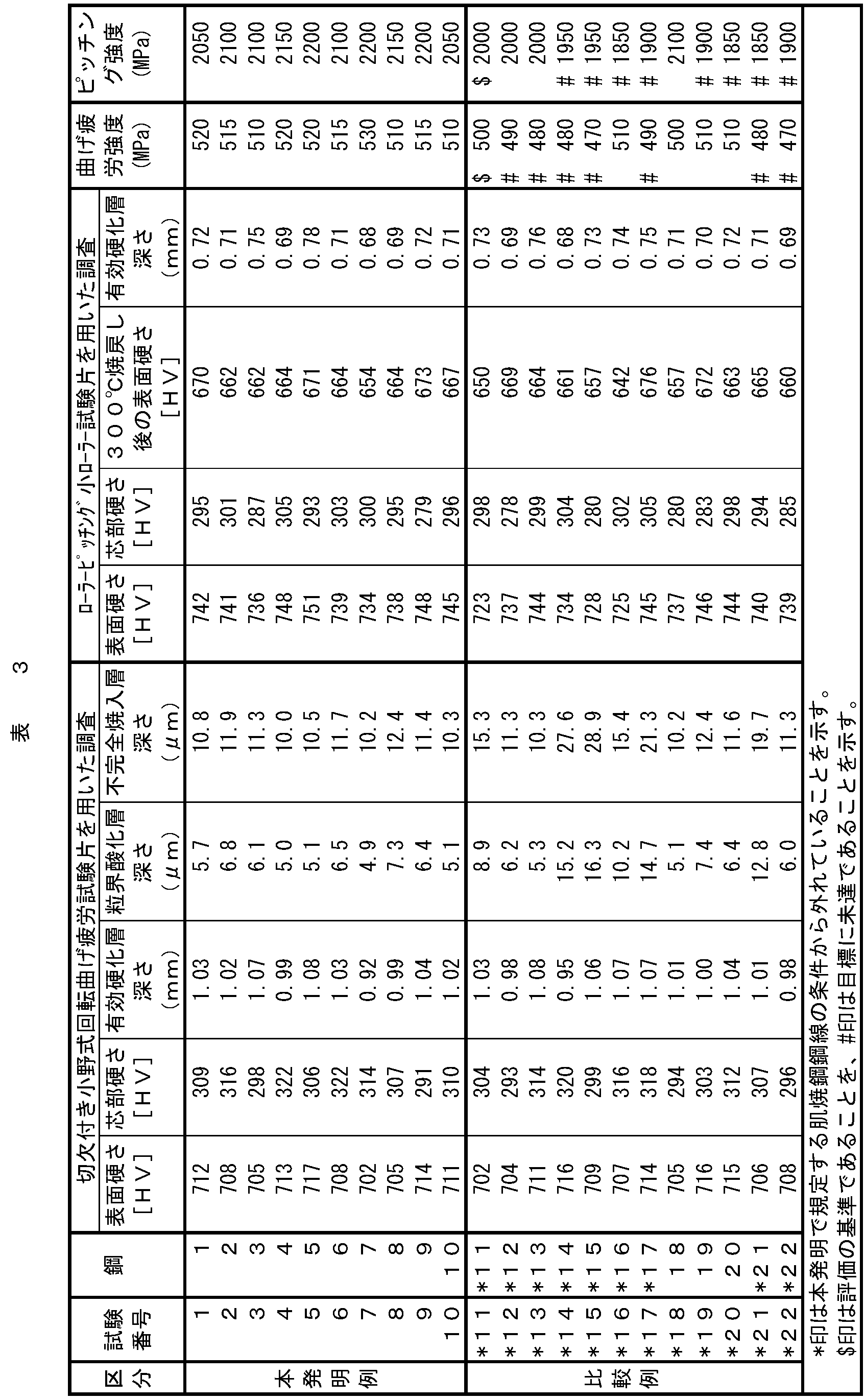
- test numbers 12 to 22 of comparative examples that deviate from the conditions specified in the present invention, at least one of cold workability, coarse grain resistance, bending fatigue strength and pitching strength is present. Inferior.
- test number 12 since Fn1 of steel 12, that is, [Mn / S] is below the range specified in the present invention, cold workability is inferior. Further, the bending fatigue strength is 490 MPa, which is lower than the test number 11.
- test number 13 since Fn1 of steel 13, that is, [Mn / S] exceeds the range defined in the present invention, cold workability is inferior. Further, the bending fatigue strength is 480 MPa, which is lower than the test number 11.
- test number 14 since Fn2 of steel 14, that is, [Cr / (Si + 2Mn)] is below the range defined in the present invention, the bending fatigue strength is 480 MPa, which is lower than test number 11. Also, the pitching strength is 1950 MPa, which is lower than the test number 11.
- test number 15 since Fn2 of steel 15, that is, [Cr / (Si + 2Mn)] exceeds the range defined in the present invention, the bending fatigue strength is 470 MPa, which is lower than test number 11. Also, the pitching strength is 1950 MPa, which is lower than the test number 11.
- test number 16 since the Fn3 of steel 16, that is, [Si ⁇ Cr] is below the range defined in the present invention, the pitching strength is 1850 MPa, which is lower than test number 11.
- test number 17 Fn3 of steel 17, that is, [Si ⁇ Cr] exceeds the range specified in the present invention, so the bending fatigue strength is 490 MPa, which is lower than test number 11. Also, the pitching strength is 1900 MPa, which is lower than the test number 11.
- test number 18 Although the chemical composition of the steel 18 is within the range specified by the present invention, the hardness at the position of 50 ⁇ m from the surface is 254 in HV, which is higher than the specification of the present invention, so that it is cold workability. Is inferior.
- test number 19 Although the chemical composition of steel 19 is within the range defined by the present invention, Al precipitates and Nb precipitates having an equivalent circle diameter of 100 nm or more at a position 1/2 the radius from the surface. And the total number of Al precipitates and Nb precipitates having an equivalent circle diameter of 5 nm or more and less than 100 nm is within the range defined by the present invention. Below. For this reason, the anti-roughening property and the pitching strength are inferior to those of Test No. 11.
- test number 21 the contents of Mn, S and O of steel 21 are higher than the values specified in the present invention, and the Cr content is also higher than the values specified in the present invention. Therefore, the cold workability is inferior, and large hard inclusions of type B of grade 2.5 are observed.
- the bending fatigue strength is 480 MPa and the pitching strength is 1850 MPa, which is lower than that of test number 11.
- test number 22 the Ti content of steel 22 is higher than the value specified in the present invention. Therefore, a large type D inclusion of type 1.5 of class 1.5 is observed, and the bending fatigue strength is 470 MPa and the pitching strength is 1900 MPa, which is lower than test number 11.
- the case-hardened steel wire of the present invention is excellent in cold workability and has a low component cost, and the carburized parts made from this case-hardened steel wire are made of “chrome molybdenum” defined in JIS G 4052 (2008). It has bending fatigue strength, pitting strength, and coarse grain resistance, which are the same as or higher than those of carburized parts made of SCM420H of “steel”. For this reason, the case-hardened steel wire of the present invention is suitable for use as a material for carburized parts such as gears and shafts that require high bending fatigue strength and high wear resistance in order to reduce weight and torque. .
Landscapes
- Chemical & Material Sciences (AREA)
- Engineering & Computer Science (AREA)
- Materials Engineering (AREA)
- Mechanical Engineering (AREA)
- Metallurgy (AREA)
- Organic Chemistry (AREA)
- Chemical Kinetics & Catalysis (AREA)
- Physics & Mathematics (AREA)
- Thermal Sciences (AREA)
- Crystallography & Structural Chemistry (AREA)
- Heat Treatment Of Steel (AREA)
Abstract
Description
N(%)≧-0.2×Nb(%)+0.028
Al(%)≧2.0×{N(%)-0.15×Nb(%)}
の範囲で含有させ、さらにO≦15ppm、S≦0.015%に規制したことを特徴とする「はだ焼鋼」が開示されている。
C:0.10~0.24%、
Si:0.16~0.35%、
Mn:0.40~1.00%、
S:0.005~0.050%、
Cr:1.65~1.90%、
Al:0.015~0.060%、
Nb:0.005~0.060%、
N:0.0130~0.0250%、
Cu:0~0.20%、
Ni:0~0.20%、
V:0~0.20%、
Ca:0~0.0050%、
残部:Feおよび不純物であり、
下記の(i)式、(ii)式および(iii)式で表されるFn1、Fn2およびFn3の値が、それぞれ、15≦Fn1≦150、0.75≦Fn2≦1.40および0.30≦Fn3≦0.65を満足し、
不純物中のP、Ti、MoおよびOがそれぞれ、P:0.020%以下、Ti:0.005%以下、Mo:0.03%以下およびO:0.0020%以下であって、
表面から50μm位置の硬さがHVで250以下であり、
表面から半径の1/2位置において、円相当直径が100nm以上の、Alの析出物とNbの析出物との合計の個数が、100μm2中に100個以下、かつ円相当直径が5nm以上で100nm未満の、Alの析出物とNbの析出物との合計の個数が、25μm2中に100個以上である、肌焼鋼鋼線。
Fn1=Mn/S・・・(i)
Fn2=Cr/(Si+2Mn)・・・(ii)
Fn3=Si×Cr・・・(iii)
ただし、上記式中の元素記号は、その元素の質量%での含有量を表す。
Cu:0.05~0.20%および
Ni:0.05~0.20%から選択される1種以上を含有する、上記(1)に記載の肌焼鋼鋼線。
V:0.05~0.20%を含有する、上記(1)または(2)に記載の肌焼鋼鋼線。
Ca:0.0003~0.0050%を含有する、上記(1)から(3)までのいずれかに記載の肌焼鋼鋼線。
C:0.10~0.24%
Cは、歯車、シャフトなど浸炭部品の強度確保のために必須の元素であり、0.10%以上の含有量が必要である。しかしながら、Cの含有量が多すぎると硬さが大きくなって被削性の低下を招き、特に、その含有量が0.24%を超えると、硬さ上昇に伴う被削性の低下が著しくなる。したがって、Cの含有量を0.10~0.24%とする。なお、Cの含有量は、0.13%以上であることが好ましく、0.23%以下であることが好ましい。
Siは、焼入性を向上させる作用および脱酸作用を有する。また、Siは焼戻し軟化に対する抵抗を有し、歯車などの摺動表面が高温にさらされた状況下において、表面の軟化を防ぐ効果がある。これらの効果を得るには、0.16%以上のSiを含有する必要がある。しかしながら、Siは酸化性の元素であるため、その含有量が多くなると、浸炭ガス中に含まれる微量のH2OまたはCO2によってSiが選択酸化され、鋼表面にSi酸化物が生成されるので、浸炭異常層である粒界酸化層および不完全焼入層の深さが大きくなる。そして、浸炭異常層の深さが大きくなると、曲げ疲労強度およびピッチング強度の低下を招く。また、Siの含有量が多くなると、焼戻し軟化に対する抵抗効果が飽和するだけでなく、浸炭性を阻害し、さらに被削性が低下する。特に、Siの含有量が0.35%を超えると、浸炭異常層の深さ増大および浸炭性の阻害による表面硬さ低下によって、曲げ疲労強度およびピッチング強度の低下が著しくなり、被削性の低下も著しくなる。したがって、Siの含有量を0.16~0.35%とする。Siの含有量は、0.18%以上であることが好ましく、0.30%以下であることが好ましい。
Mnは、焼入性を向上させる作用および脱酸作用を有する。また、Mnは焼戻し軟化を抑制する効果も有する。これらの効果を得るには、0.40%以上のMn含有量が必要である。しかしながら、Mnの含有量が多くなると、硬さが大きくなって被削性の低下を招き、特に、その含有量が1.00%を超えると、硬さ上昇に伴う被削性の低下が著しくなる。しかも、Siと同様に、Mnは酸化性の元素であるため、その含有量が多くなると、鋼表面にMn酸化物が生成されるので、浸炭異常層である粒界酸化層および不完全焼入層の深さが大きくなる。そして、浸炭異常層の深さが大きくなると、曲げ疲労強度およびピッチング強度の低下を招き、特に、Mnの含有量が1.00%を超えると、浸炭異常層の深さ増大による曲げ疲労強度およびピッチング強度の低下が著しくなる。したがって、Mnの含有量を0.40~1.00%とする。Mnの含有量は、0.50%以上であることが好ましく、0.95%以下であることが好ましい。
Sは、Mnと結合してMnSを形成し、被削性を向上させる作用がある。この効果を得るには、0.005%以上のSを含有させる必要がある。しかしながら、Sの含有量が0.050%を超えると、粗大なMnSを形成して、冷間鍛造性および曲げ疲労強度が低下する。したがって、Sの含有量を0.005~0.050%とする。Sの含有量は、0.010%以上であることが好ましく、0.040%以下であることが好ましい。
Crは、焼入性を向上させる効果を有する。Crは、焼戻し軟化に対する抵抗を有し、歯車、シャフトなど浸炭部品の摺動表面が高温にさらされた状況下において、表面の軟化を防ぐ効果もある。これらの効果を得るには、1.65%以上のCr含有量が必要である。しかしながら、Crの含有量が多くなると、硬さが大きくなって被削性の低下を招き、特に、その含有量が1.90%を超えると、硬さ上昇に伴う被削性の低下が著しくなる。しかも、SiおよびMnと同様に、Crは酸化性の元素であるため、その含有量が多くなると、鋼表面にCr酸化物が生成されるので、浸炭異常層である粒界酸化層および不完全焼入層の深さが大きくなる。そして、浸炭異常層の深さが大きくなると、曲げ疲労強度およびピッチング強度の低下を招き、特に、Crの含有量が1.90%を超えると、浸炭異常層の深さ増大による曲げ疲労強度およびピッチング強度の低下が著しくなる。したがって、Crの含有量を1.65~1.90%とする。Crの含有量は、1.85%以下であることが好ましい。
Alは、脱酸作用を有する。また、Alには、Nと結合してAlNを形成し、結晶粒を微細化して鋼を強化する作用もある。しかしながら、Alの含有量が0.015%未満では、前記の効果を得難い。一方、Alの含有量が過剰になると、硬質で粗大なAl2O3形成による被削性の低下をきたし、さらに、曲げ疲労強度も低下する。特に、Alの含有量が0.060%を超えると、被削性および曲げ疲労強度の低下が著しくなる。したがって、Alの含有量を0.015~0.060%とする。Alの含有量は、0.020%以上であることが好ましく、0.055%以下であることが好ましい。
Nbは、CおよびNと結合して微細な炭化物、窒化物または炭窒化物を形成して結晶粒を微細化し、曲げ疲労強度およびピッチング強度を向上させる効果を有する。この効果を得るには、0.005%以上のNb含有量が必要である。しかしながら、Nbの含有量が過剰になると熱間延性の低下を招き、特に、その含有量が0.060%を超えると、熱間延性の低下が著しくなって、熱間圧延、熱間鍛造など熱間加工時に表面キズが発生しやすくなる。したがって、Nbの含有量を0.005~0.060%とする。Nbの含有量は、0.015%以上であることが好ましく、0.050%以下であることが好ましい。
Nは、窒化物を形成することにより結晶粒を微細化させ、曲げ疲労強度を向上させる効果を有する。この効果を得るには、Nを0.0130%以上含有する必要がある。しかしながら、Nの含有量が過剰になると、粗大な窒化物を形成して靱性の低下を招き、特に、その含有量が0.0250%を超えると、靱性の低下および冷間鍛造性の低下が著しくなる。また、タイプDの大型介在物が生成されやすくなり、曲げ疲労強度およびピッチング強度が低下する。したがって、Nの含有量を0.0130~0.0250%とする。なお、Nの含有量は、0.0200%以下であることが好ましい。
MnおよびSの含有量が、上述した範囲にあっても、粗大なMnSが生成すると、曲げ疲労強度の低下が生じる。したがって、高い曲げ疲労強度を確保するためには、粗大なMnSの生成を抑制することが必要である。しかも、上記の粗大なMnSは、冷間鍛造時の割れの起点ともなるので、冷間鍛造時の割れを抑制するためには、粗大なMnSを極力少なくすることが必要である。このためには、MnおよびSの含有量のバランスが重要であり、下記(i)式で表されるFn1を一定範囲内とする必要がある。
Fn1=Mn/S・・・(i)
ただし、上記式中の元素記号は、その元素の質量%での含有量を表す。
NiおよびMoを極力含有させることなく、高い曲げ疲労強度と高いピッチング強度とを具備させるためには、焼入性を確保しつつ、浸炭異常層である粒界酸化層および不完全焼入層の深さを小さくする必要がある。そして、そのためには酸化性の元素のうちで、特に、Cr、SiおよびMnの含有量を前記の範囲にしたうえで、これらの元素の含有量バランスとしての下記(ii)式で表されるFn2を0.75~1.40の範囲内とする必要がある。
Fn2=Cr/(Si+2Mn)・・・(ii)
ただし、上記式中の元素記号は、その元素の質量%での含有量を表す。
NiおよびMoを極力含有させることなく、高いピッチング強度を具備させるためには、高温強度すなわち焼戻し軟化抵抗を向上させる必要があり、具体的には、焼戻し軟化抵抗を向上させる元素のうちで、特に、SiおよびCrの含有量を前記の範囲にしたうえで、下記(iii)式で表わされるFn3を0.30~0.65の範囲内とする必要がある。
Fn3=Si×Cr・・・(iii)
ただし、上記式中の元素記号は、その元素の質量%での含有量を表す。
Pは、鋼に含有される不純物であり、結晶粒界に偏析して鋼を脆化させる。特に、その含有量が0.020%を超えると、脆化の程度が著しくなる。したがって、Pの含有量を0.020%以下とする。Pの含有量は0.015%以下とすることが好ましい。
Tiは、Nとの親和性が高いので、鋼中のNと結合して硬質で粗大なタイプDの非金属介在物であるTiNを形成し、曲げ疲労強度およびピッチング強度を低下させ、さらに、被削性も低下させてしまう。したがって、Tiの含有量を0.005%以下とする。
Moは、高価な元素であり、含有させると成分コストの上昇につながる。また、不純物中のMoの含有量が変動した場合には、機械的性質が安定しなくなる。したがって、Moの含有量を0.03%以下とする。
O(酸素)は、鋼中のSi、Alなどと結合して、酸化物を生成する。酸化物のうちでも、特に、タイプBの非金属介在物であるAl2O3は硬質であるため、被削性を低下させ、さらに、曲げ疲労強度およびピッチング強度の低下も招く。したがって、Oの含有量を0.0020%以下とする。Oの含有量は0.0015%以下とすることが好ましい。
〈1〉Cu:0~0.20%およびNi:0~0.20%
〈2〉V:0~0.20%
〈3〉Ca:0~0.0050%
CuおよびNiは、いずれも、焼入性を高める作用を有する。このため、より大きな焼入性を得たい場合には以下の範囲で含有してもよい。
Cuは、焼入性を高める作用を有するので、さらなる焼入性向上のためにCuを含有させてもよい。しかしながら、Cuは高価な元素であるとともに、含有量が多くなると熱間加工性の低下を招き、特に、0.20%を超えると、熱間加工性の低下が著しくなる。したがって、含有させる場合のCuの量を0.20%以下とする。
Niは、焼入性を高める作用を有する。さらに、Niは、靱性を向上させる作用を有し、非酸化性の元素であるため、浸炭時に粒界酸化層の深さを増大させずに鋼表面を強靱化することもできる。このため、これらの効果を得るためにNiを含有させてもよい。しかしながら、Niは高価な元素であり、過度の添加は成分コストの上昇につながり、特に、Niの含有量が0.20%を超えると、コスト上昇が大きくなる。したがって、含有させる場合のNiの量を0.20%以下とする。
Vは、CおよびNと結合して微細な炭化物、窒化物や炭窒化物を形成して結晶粒を微細化し、曲げ疲労強度およびピッチング強度を向上させる効果を有するので、こうした効果を得るためにVを含有させてもよい。しかしながら、Vの含有量が過剰になると熱間延性の低下を招き、特に、その含有量が0.20%を超えると、熱間延性の低下が著しくなって、熱間圧延、熱間鍛造など熱間加工時に表面キズが発生しやすくなる。したがって、含有させる場合のVの量を0.20%以下とする。なお、Vの量は、0.10%以下とすることが好ましい。
Caは、被削性を改善する作用を有する。このため、被削性向上のためにCaを含有させてもよい。しかしながら、過度のCa添加は成分コストの上昇につながり、特に、Caの含有量が0.0050%を超えると、被削性向上効果が飽和するのでコストが嵩むばかりであって経済性が損なわれる。しかも、Caの含有量が0.0050%を超える場合には、粗大な酸化物を形成して曲げ疲労強度およびピッチング強度の低下も招く。したがって、含有させる場合のCaの量を0.0050%以下とする。なお、Caの量は、0.0030%以下とすることが好ましい。
冷間加工素材である鋼線の硬さが高い場合には、冷間加工、なかでも冷間鍛造時に、表面疵による冷間加工割れを抑制することができない。しかしながら、鋼線の硬さが低い場合には、具体的には、鋼線の表面から50μm位置の硬さがHVで250以下の場合には、高い冷間加工性が得られるので、厳しい加工を強いられる部品の冷間加工時の割れを防ぐことができる。
本発明に係る肌焼鋼鋼線は、表面から半径の1/2位置において、円相当直径が100nm以上の、Alの析出物とNbの析出物との合計の個数が、100μm2中に100個以下、かつ円相当直径が5nm以上で100nm未満の、Alの析出物とNbの析出物との合計の個数が、25μm2中に100個以上でなければならない。

各鋳片は、1250℃で表2に記載の時間保持した後、分塊圧延して160mm角のビレットを製造した。
上記分塊圧延して製造した160mm角のビレットの表面疵をグラインダーで除去し、1100℃で50分保持した後、鋼2、6、11および18については、熱間圧延して直径が35mmの棒鋼を作製し、また、鋼9については、熱間圧延して直径が35mmのバーインコイルを作製した。上記棒鋼とバーインコイルの圧延仕上げ温度および800~500℃の温度域の冷却速度は、表2に示すとおりである。
直径が45mmの各棒鋼に、ピーリング処理を行い、直径が35mmの棒鋼に仕上げた。
直径35mmの棒鋼およびバーインコイルに、760℃で10時間保持し、650℃までを9時間かけて徐冷後、放冷する球状化焼鈍を施した。
球状化焼鈍した後、酸洗してから、潤滑剤を用いて冷間で引抜加工し、直径が33mmのいわゆる「棒状」の鋼線に仕上げた。なお、この時の断面減少率は11.1%である。
前記直径が33mmの各鋼線の中心部から、圧延方向または鍛錬軸に平行に、図1に示す粗形状の切欠付き小野式回転曲げ疲労試験片、図2に示す粗形状のローラーピッチング小ローラー試験片、図3に示す冷間加工性評価用の試験片および図4に示す耐粗粒化特性評価用の試験片を切り出した。
上記〔6〕で切り出した粗形状の切欠付き小野式回転曲げ疲労試験片およびローラーピッチング小ローラー試験片に対して、図6に示すヒートパターンによる「浸炭焼入-焼戻し」を施した。また、〔6〕で切り出した粗形状のローラーピッチング大ローラー試験片に対して、図7に示すヒートパターンによる「浸炭焼入-焼戻し」を施した。
浸炭焼入-焼戻し処理を施した上記の各試験片を仕上げ加工して、図8に示す切欠付き小野式回転曲げ疲労試験片、図9に示すローラーピッチング小ローラー試験片および図10に示すローラーピッチング大ローラー試験片を作製した。
前記の鏡面研磨した硬さ測定のための試験片の表面から50μm位置10点のHV(ビッカース硬さ)を、JIS Z 2244(2009)に記載の「ビッカース硬さ試験-試験方法」に準拠して、試験力を0.98Nとしてビッカース硬さ試験機で測定し、上記10点の算術平均値を表面から50μm位置の硬さとした。
前記の一般的な方法で作製した抽出レプリカ試料を、エネルギー分散型X線分析装置(以下、「EDX」という。)を装備した透過型電子顕微鏡(以下、「TEM」という。)を使用して観察し、Alの析出物であるAlNと、Nbの析出物であるNbC、NbNおよびNb(CN)とについて、合計の析出密度を調査した。
前記〔6〕のようにして作製した図3の試験片を常温で、長さ方向を高さとして油圧プレスによって圧縮し、外周に割れが発生するまで圧縮した。なお、各鋼について油圧プレスを用いた圧縮試験を5個ずつ行ない、割れを拡大鏡で観察した。5本の試験片のうち3本以上の試験片で割れが認められる場合の圧縮率を限界圧縮率と定義し、限界圧縮率がJIS G 4052(2008)に規定されたSCM420Hに相当する鋼である鋼11と同じ程度あるいはそれを上回る場合に、冷間加工性に優れると評価して、これを目標とした。
前記〔6〕のようにして作製した図4の試験片を常温で、長さ方向を高さとして油圧プレスによって高さ70%分の圧縮を行った。その後、浸炭での加熱を模擬するために、試験片を950℃に加熱し、5時間保持した後、水焼入を行い、各試験片を中心軸を含むように縦断、すなわち、高さ方向に対して平行に切断して、切断面が被検面になるようにして樹脂に埋め込み、前記の面が鏡面仕上げになるように研磨した。次いで、界面活性剤を添加したピクリン酸飽和水溶液で腐食し、光学顕微鏡を用いて倍率100倍でランダムに各10視野観察し、JIS G 0551(2013)に規定の結晶粒度番号を調査し、上記10視野の値を算術平均して各試験片のオーステナイト結晶粒度番号を求めた。なお、オーステナイト結晶粒度番号が、JIS G 4052(2008)に規定されたSCM420Hに相当する鋼である鋼11と同じ程度あるいはそれを上回る場合に、耐粗粒化特性に優れると評価して、これを目標とした。
直径が33mmの各鋼線の残りを、920℃で30分保持した後、水焼入した。水焼入後は、鋼線の長さ方向に平行に、その中心線をとおって切断した面が被検面になるようにして樹脂に埋め込み、前記の面が鏡面仕上げになるように研磨した。
前記〔7〕のようにして浸炭焼入-焼戻し処理した粗形状の切欠付き小野式回転曲げ疲労試験片を用いて、その直径8mmの切欠部を横断し、切断面が被検面になるように樹脂に埋め込んだ後、前記面が鏡面仕上げになるように研磨し、マイクロビッカース硬度計を使用して表面硬さおよび芯部硬さを調査した。
前記〔7〕の、浸炭焼入-焼戻し処理しただけで上記《6》の表面硬さおよび芯部硬さの調査に用いた、粗形状の切欠付き小野式回転曲げ疲労試験片とローラーピッチング小ローラー試験片の樹脂埋めした試験片を使用して、有効硬化層深さの調査を行った。
前記《6》および《7》で用いた粗形状の切欠付き小野式回転曲げ疲労試験片の樹脂埋めした試験片を使用して、粒界酸化層深さおよび不完全焼入層深さの調査を行った。
前記〔8〕の仕上げ加工した切欠付き小野式回転曲げ疲労試験片を用いて、下記の試験条件によって小野式回転曲げ疲労試験を実施し、繰返し数が107回において破断しない最大の強度で曲げ疲労強度を評価した。
・雰囲気:大気中
・回転数:3000rpm
前記〔8〕の仕上げ加工したローラーピッチング小ローラー試験片およびローラーピッチング大ローラー試験片を用いて、下記の試験条件でローラーピッチング試験を実施した。すなわち、ローラーピッチング小ローラー試験片およびローラーピッチング大ローラー試験片を接触させた状態で回転させ、接触部には下記の条件で潤滑油を噴き付けた。繰り返し数107回において、ローラーピッチング小ローラー試験片表面に幅が1mm以上のピッチングが発生しない最大の強度でピッチング強度を評価した。ピッチング強度がJIS G 4052(2008)に規定されたSCM420Hに相当する鋼である鋼11と同じ程度あるいはそれを上回る場合に、ピッチング強度に優れると評価して、これを目標とした。
・ローラーピッチング小ローラー試験片の回転数:1500rpm
・潤滑:油温100℃のオートマチックトランスミッション用潤滑油を、2.0リットル/分の割合で、ローラーピッチング小ローラー試験片とローラーピッチング大ローラー試験片の接触部に噴出させて実施
{(V2-V1)/V1}×100
Claims (4)
- 化学組成が、質量%で、
C:0.10~0.24%、
Si:0.16~0.35%、
Mn:0.40~1.00%、
S:0.005~0.050%、
Cr:1.65~1.90%、
Al:0.015~0.060%、
Nb:0.005~0.060%、
N:0.0130~0.0250%、
Cu:0~0.20%、
Ni:0~0.20%、
V:0~0.20%、
Ca:0~0.0050%、
残部:Feおよび不純物であり、
下記の(i)式、(ii)式および(iii)式で表されるFn1、Fn2およびFn3の値が、それぞれ、15≦Fn1≦150、0.75≦Fn2≦1.40および0.30≦Fn3≦0.65を満足し、
不純物中のP、Ti、MoおよびOがそれぞれ、P:0.020%以下、Ti:0.005%以下、Mo:0.03%以下およびO:0.0020%以下であって、
表面から50μm位置の硬さがHVで250以下であり、
表面から半径の1/2位置において、円相当直径が100nm以上の、Alの析出物とNbの析出物との合計の個数が、100μm2中に100個以下、かつ円相当直径が5nm以上で100nm未満の、Alの析出物とNbの析出物との合計の個数が、25μm2中に100個以上である、肌焼鋼鋼線。
Fn1=Mn/S・・・(i)
Fn2=Cr/(Si+2Mn)・・・(ii)
Fn3=Si×Cr・・・(iii)
ただし、上記式中の元素記号は、その元素の質量%での含有量を表す。 - 前記化学組成が、質量%で、
Cu:0.05~0.20%および
Ni:0.05~0.20%から選択される1種以上を含有する、請求項1に記載の肌焼鋼鋼線。 - 前記化学組成が、質量%で、
V:0.05~0.20%を含有する、請求項1または2に記載の肌焼鋼鋼線。 - 前記化学組成が、質量%で、
Ca:0.0003~0.0050%を含有する、請求項1から3までのいずれかに記載の肌焼鋼鋼線。
Priority Applications (1)
| Application Number | Priority Date | Filing Date | Title |
|---|---|---|---|
| JP2016506412A JP6172378B2 (ja) | 2014-03-03 | 2015-02-18 | 肌焼鋼鋼線 |
Applications Claiming Priority (2)
| Application Number | Priority Date | Filing Date | Title |
|---|---|---|---|
| JP2014-040197 | 2014-03-03 | ||
| JP2014040197 | 2014-03-03 |
Publications (1)
| Publication Number | Publication Date |
|---|---|
| WO2015133273A1 true WO2015133273A1 (ja) | 2015-09-11 |
Family
ID=54055083
Family Applications (1)
| Application Number | Title | Priority Date | Filing Date |
|---|---|---|---|
| PCT/JP2015/054408 Ceased WO2015133273A1 (ja) | 2014-03-03 | 2015-02-18 | 肌焼鋼鋼線 |
Country Status (2)
| Country | Link |
|---|---|
| JP (1) | JP6172378B2 (ja) |
| WO (1) | WO2015133273A1 (ja) |
Cited By (1)
| Publication number | Priority date | Publication date | Assignee | Title |
|---|---|---|---|---|
| JP2019035112A (ja) * | 2017-08-16 | 2019-03-07 | 新日鐵住金株式会社 | 鋼材 |
Citations (7)
| Publication number | Priority date | Publication date | Assignee | Title |
|---|---|---|---|---|
| JP2009191322A (ja) * | 2008-02-15 | 2009-08-27 | Sanyo Special Steel Co Ltd | 浸炭部品用の耐粗粒化特性に優れたはだ焼鋼 |
| JP2009249685A (ja) * | 2008-04-07 | 2009-10-29 | Sumitomo Metal Ind Ltd | 肌焼鋼 |
| JP2010150566A (ja) * | 2008-12-24 | 2010-07-08 | Sumitomo Metal Ind Ltd | 真空浸炭または真空浸炭窒化用の鋼材 |
| JP2012117102A (ja) * | 2010-11-30 | 2012-06-21 | Kobe Steel Ltd | 肌焼鋼、およびこれを用いた機械構造部品 |
| JP2012158827A (ja) * | 2011-02-03 | 2012-08-23 | Sumitomo Metal Ind Ltd | 表面硬化用熱間加工鋼材 |
| JP2013139604A (ja) * | 2012-01-05 | 2013-07-18 | Nippon Steel & Sumitomo Metal Corp | 熱間圧延棒鋼または線材 |
| JP2015067858A (ja) * | 2013-09-30 | 2015-04-13 | 新日鐵住金株式会社 | 肌焼鋼鋼材 |
-
2015
- 2015-02-18 WO PCT/JP2015/054408 patent/WO2015133273A1/ja not_active Ceased
- 2015-02-18 JP JP2016506412A patent/JP6172378B2/ja active Active
Patent Citations (7)
| Publication number | Priority date | Publication date | Assignee | Title |
|---|---|---|---|---|
| JP2009191322A (ja) * | 2008-02-15 | 2009-08-27 | Sanyo Special Steel Co Ltd | 浸炭部品用の耐粗粒化特性に優れたはだ焼鋼 |
| JP2009249685A (ja) * | 2008-04-07 | 2009-10-29 | Sumitomo Metal Ind Ltd | 肌焼鋼 |
| JP2010150566A (ja) * | 2008-12-24 | 2010-07-08 | Sumitomo Metal Ind Ltd | 真空浸炭または真空浸炭窒化用の鋼材 |
| JP2012117102A (ja) * | 2010-11-30 | 2012-06-21 | Kobe Steel Ltd | 肌焼鋼、およびこれを用いた機械構造部品 |
| JP2012158827A (ja) * | 2011-02-03 | 2012-08-23 | Sumitomo Metal Ind Ltd | 表面硬化用熱間加工鋼材 |
| JP2013139604A (ja) * | 2012-01-05 | 2013-07-18 | Nippon Steel & Sumitomo Metal Corp | 熱間圧延棒鋼または線材 |
| JP2015067858A (ja) * | 2013-09-30 | 2015-04-13 | 新日鐵住金株式会社 | 肌焼鋼鋼材 |
Cited By (2)
| Publication number | Priority date | Publication date | Assignee | Title |
|---|---|---|---|---|
| JP2019035112A (ja) * | 2017-08-16 | 2019-03-07 | 新日鐵住金株式会社 | 鋼材 |
| JP7066997B2 (ja) | 2017-08-16 | 2022-05-16 | 日本製鉄株式会社 | 鋼材 |
Also Published As
| Publication number | Publication date |
|---|---|
| JPWO2015133273A1 (ja) | 2017-04-06 |
| JP6172378B2 (ja) | 2017-08-02 |
Similar Documents
| Publication | Publication Date | Title |
|---|---|---|
| JP6241136B2 (ja) | 肌焼鋼鋼材 | |
| JP5163241B2 (ja) | 肌焼鋼 | |
| JP5858204B2 (ja) | 熱間鍛造用鋼材およびその製造方法ならびにその鋼材を用いた熱間鍛造素形材の製造方法 | |
| JP5299118B2 (ja) | 真空浸炭用鋼および真空浸炭部品 | |
| JPWO2014171472A1 (ja) | 肌焼用鋼材と肌焼鋼部品 | |
| JP4964063B2 (ja) | 冷間鍛造性および結晶粒粗大化防止特性に優れた肌焼鋼およびそれから得られる機械部品 | |
| CN103562423B (zh) | 滚动疲劳特性优异的钢材 | |
| JP5163242B2 (ja) | 肌焼鋼 | |
| JP5886119B2 (ja) | 肌焼鋼鋼材 | |
| JP2021127503A (ja) | 軸受軌道用鋼材、および軸受軌道 | |
| CN111684094A (zh) | 进行渗碳处理的部件用钢材 | |
| CN113631746A (zh) | 渗碳部件及其制造方法 | |
| JP2021127504A (ja) | 軸受軌道用鋼材、および軸受軌道 | |
| JP5406687B2 (ja) | 転動疲労寿命に優れた鋼材 | |
| JP6225613B2 (ja) | 肌焼鋼鋼材 | |
| JP2006161144A (ja) | 高温浸炭特性と熱間鍛造性に優れた浸炭用圧延鋼材 | |
| CN108138287A (zh) | 机械结构用钢及高频淬火钢部件 | |
| JP2017133052A (ja) | 浸炭時の粗大粒防止特性と疲労特性と被削性に優れた肌焼鋼およびその製造方法 | |
| JP5206459B2 (ja) | 肌焼鋼 | |
| JP6172378B2 (ja) | 肌焼鋼鋼線 | |
| JP6488945B2 (ja) | 高強度冷間鍛造用肌焼鋼 | |
| JP6265048B2 (ja) | 肌焼鋼 | |
| JP5937852B2 (ja) | 肌焼用鋼部品 | |
| JP2022170056A (ja) | 鋼材 | |
| JP7360060B2 (ja) | 鋼及び軸受 |
Legal Events
| Date | Code | Title | Description |
|---|---|---|---|
| 121 | Ep: the epo has been informed by wipo that ep was designated in this application |
Ref document number: 15757852 Country of ref document: EP Kind code of ref document: A1 |
|
| ENP | Entry into the national phase |
Ref document number: 2016506412 Country of ref document: JP Kind code of ref document: A |
|
| NENP | Non-entry into the national phase |
Ref country code: DE |
|
| WWE | Wipo information: entry into national phase |
Ref document number: IDP00201606454 Country of ref document: ID |
|
| 122 | Ep: pct application non-entry in european phase |
Ref document number: 15757852 Country of ref document: EP Kind code of ref document: A1 |