WO2015133253A1 - 電池パック - Google Patents
電池パック Download PDFInfo
- Publication number
- WO2015133253A1 WO2015133253A1 PCT/JP2015/054149 JP2015054149W WO2015133253A1 WO 2015133253 A1 WO2015133253 A1 WO 2015133253A1 JP 2015054149 W JP2015054149 W JP 2015054149W WO 2015133253 A1 WO2015133253 A1 WO 2015133253A1
- Authority
- WO
- WIPO (PCT)
- Prior art keywords
- battery
- housing
- lid member
- battery pack
- harness
- Prior art date
- Legal status (The legal status is an assumption and is not a legal conclusion. Google has not performed a legal analysis and makes no representation as to the accuracy of the status listed.)
- Ceased
Links
Images
Classifications
-
- H—ELECTRICITY
- H01—ELECTRIC ELEMENTS
- H01M—PROCESSES OR MEANS, e.g. BATTERIES, FOR THE DIRECT CONVERSION OF CHEMICAL ENERGY INTO ELECTRICAL ENERGY
- H01M50/00—Constructional details or processes of manufacture of the non-active parts of electrochemical cells other than fuel cells, e.g. hybrid cells
- H01M50/50—Current conducting connections for cells or batteries
- H01M50/572—Means for preventing undesired use or discharge
- H01M50/574—Devices or arrangements for the interruption of current
- H01M50/579—Devices or arrangements for the interruption of current in response to shock
-
- H—ELECTRICITY
- H01—ELECTRIC ELEMENTS
- H01M—PROCESSES OR MEANS, e.g. BATTERIES, FOR THE DIRECT CONVERSION OF CHEMICAL ENERGY INTO ELECTRICAL ENERGY
- H01M50/00—Constructional details or processes of manufacture of the non-active parts of electrochemical cells other than fuel cells, e.g. hybrid cells
- H01M50/20—Mountings; Secondary casings or frames; Racks, modules or packs; Suspension devices; Shock absorbers; Transport or carrying devices; Holders
- H01M50/204—Racks, modules or packs for multiple batteries or multiple cells
- H01M50/207—Racks, modules or packs for multiple batteries or multiple cells characterised by their shape
- H01M50/209—Racks, modules or packs for multiple batteries or multiple cells characterised by their shape adapted for prismatic or rectangular cells
-
- H—ELECTRICITY
- H01—ELECTRIC ELEMENTS
- H01M—PROCESSES OR MEANS, e.g. BATTERIES, FOR THE DIRECT CONVERSION OF CHEMICAL ENERGY INTO ELECTRICAL ENERGY
- H01M50/00—Constructional details or processes of manufacture of the non-active parts of electrochemical cells other than fuel cells, e.g. hybrid cells
- H01M50/20—Mountings; Secondary casings or frames; Racks, modules or packs; Suspension devices; Shock absorbers; Transport or carrying devices; Holders
- H01M50/262—Mountings; Secondary casings or frames; Racks, modules or packs; Suspension devices; Shock absorbers; Transport or carrying devices; Holders with fastening means, e.g. locks
- H01M50/264—Mountings; Secondary casings or frames; Racks, modules or packs; Suspension devices; Shock absorbers; Transport or carrying devices; Holders with fastening means, e.g. locks for cells or batteries, e.g. straps, tie rods or peripheral frames
-
- H—ELECTRICITY
- H01—ELECTRIC ELEMENTS
- H01M—PROCESSES OR MEANS, e.g. BATTERIES, FOR THE DIRECT CONVERSION OF CHEMICAL ENERGY INTO ELECTRICAL ENERGY
- H01M50/00—Constructional details or processes of manufacture of the non-active parts of electrochemical cells other than fuel cells, e.g. hybrid cells
- H01M50/20—Mountings; Secondary casings or frames; Racks, modules or packs; Suspension devices; Shock absorbers; Transport or carrying devices; Holders
- H01M50/271—Lids or covers for the racks or secondary casings
-
- H—ELECTRICITY
- H01—ELECTRIC ELEMENTS
- H01M—PROCESSES OR MEANS, e.g. BATTERIES, FOR THE DIRECT CONVERSION OF CHEMICAL ENERGY INTO ELECTRICAL ENERGY
- H01M50/00—Constructional details or processes of manufacture of the non-active parts of electrochemical cells other than fuel cells, e.g. hybrid cells
- H01M50/20—Mountings; Secondary casings or frames; Racks, modules or packs; Suspension devices; Shock absorbers; Transport or carrying devices; Holders
- H01M50/296—Mountings; Secondary casings or frames; Racks, modules or packs; Suspension devices; Shock absorbers; Transport or carrying devices; Holders characterised by terminals of battery packs
-
- H—ELECTRICITY
- H01—ELECTRIC ELEMENTS
- H01M—PROCESSES OR MEANS, e.g. BATTERIES, FOR THE DIRECT CONVERSION OF CHEMICAL ENERGY INTO ELECTRICAL ENERGY
- H01M2200/00—Safety devices for primary or secondary batteries
-
- H—ELECTRICITY
- H01—ELECTRIC ELEMENTS
- H01M—PROCESSES OR MEANS, e.g. BATTERIES, FOR THE DIRECT CONVERSION OF CHEMICAL ENERGY INTO ELECTRICAL ENERGY
- H01M2220/00—Batteries for particular applications
- H01M2220/20—Batteries in motive systems, e.g. vehicle, ship, plane
-
- H—ELECTRICITY
- H01—ELECTRIC ELEMENTS
- H01M—PROCESSES OR MEANS, e.g. BATTERIES, FOR THE DIRECT CONVERSION OF CHEMICAL ENERGY INTO ELECTRICAL ENERGY
- H01M50/00—Constructional details or processes of manufacture of the non-active parts of electrochemical cells other than fuel cells, e.g. hybrid cells
- H01M50/50—Current conducting connections for cells or batteries
- H01M50/502—Interconnectors for connecting terminals of adjacent batteries; Interconnectors for connecting cells outside a battery casing
- H01M50/509—Interconnectors for connecting terminals of adjacent batteries; Interconnectors for connecting cells outside a battery casing characterised by the type of connection, e.g. mixed connections
- H01M50/51—Connection only in series
-
- H—ELECTRICITY
- H01—ELECTRIC ELEMENTS
- H01M—PROCESSES OR MEANS, e.g. BATTERIES, FOR THE DIRECT CONVERSION OF CHEMICAL ENERGY INTO ELECTRICAL ENERGY
- H01M50/00—Constructional details or processes of manufacture of the non-active parts of electrochemical cells other than fuel cells, e.g. hybrid cells
- H01M50/50—Current conducting connections for cells or batteries
- H01M50/543—Terminals
- H01M50/547—Terminals characterised by the disposition of the terminals on the cells
- H01M50/55—Terminals characterised by the disposition of the terminals on the cells on the same side of the cell
-
- H—ELECTRICITY
- H01—ELECTRIC ELEMENTS
- H01M—PROCESSES OR MEANS, e.g. BATTERIES, FOR THE DIRECT CONVERSION OF CHEMICAL ENERGY INTO ELECTRICAL ENERGY
- H01M50/00—Constructional details or processes of manufacture of the non-active parts of electrochemical cells other than fuel cells, e.g. hybrid cells
- H01M50/50—Current conducting connections for cells or batteries
- H01M50/543—Terminals
- H01M50/552—Terminals characterised by their shape
- H01M50/553—Terminals adapted for prismatic, pouch or rectangular cells
-
- Y—GENERAL TAGGING OF NEW TECHNOLOGICAL DEVELOPMENTS; GENERAL TAGGING OF CROSS-SECTIONAL TECHNOLOGIES SPANNING OVER SEVERAL SECTIONS OF THE IPC; TECHNICAL SUBJECTS COVERED BY FORMER USPC CROSS-REFERENCE ART COLLECTIONS [XRACs] AND DIGESTS
- Y02—TECHNOLOGIES OR APPLICATIONS FOR MITIGATION OR ADAPTATION AGAINST CLIMATE CHANGE
- Y02E—REDUCTION OF GREENHOUSE GAS [GHG] EMISSIONS, RELATED TO ENERGY GENERATION, TRANSMISSION OR DISTRIBUTION
- Y02E60/00—Enabling technologies; Technologies with a potential or indirect contribution to GHG emissions mitigation
- Y02E60/10—Energy storage using batteries
Definitions
- the present invention relates to a battery pack having a battery module housed in a housing.
- a battery pack having battery cells housed in a housing is disclosed in Patent Document 1, for example.
- a plurality of battery cells (unit cells) are accommodated in a housing (module case).
- the battery cell When vibration or impact is applied to the battery pack, the battery cell may collide with the inner surface of the casing. For this reason, it is desired to protect the battery cell when vibration or impact is applied to the battery pack.
- An object of the present invention is to provide a battery pack that can protect battery cells.
- the battery pack including a casing having an inner surface and a battery module accommodated in the casing.
- the battery module includes a battery body having a plurality of battery cells arranged side by side, and two end plates sandwiching the battery body. At least one of the end plates has a protruding portion that protrudes toward the inner surface of the housing from the battery body.
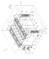
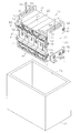
- the perspective view which shows the battery pack in one Embodiment The disassembled perspective view which shows the end plate, battery cell, and battery holder in embodiment. Sectional drawing which shows the battery pack in embodiment. The perspective view which shows the modification of a battery pack.
- the battery pack 10 has a housing 11.
- the housing 11 includes a main body 12 having an opening 12 a and a lid member 13 that closes the opening 12 a of the main body 12.
- the main body 12 has a box shape having an opening 12a.
- the lid member 13 has a flat plate shape.
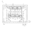
- a battery module 21 is accommodated in the housing 11.
- the battery module 21 includes a battery body 22 and two end plates 23 and 24 that sandwich the battery body 22.
- the battery body 22 includes a plurality of battery cells 25 arranged in parallel and a battery holder 40 that holds each battery cell 25.
- the battery cell 25 has a battery case 26, and an electrode assembly 27 is accommodated in the battery case 26.
- the battery case 26 includes a box-shaped case body 28 having an opening and a flat lid 29 that closes the opening of the case body 28. A positive terminal 30 and a negative terminal 31 protrude from the lid 29.
- the battery holder 40 has a rectangular flat plate-like first covering portion 41.
- a second covering portion 42 is provided at one end in the longitudinal direction of the first covering portion 41, and a third covering portion 43 is provided at the other end in the longitudinal direction of the first covering portion 41.
- Each of the second covering portion 42 and the third covering portion 43 has a rectangular flat plate shape extending in the thickness direction of the first covering portion 41.
- the longitudinal first end 42a of the second covering portion 42 and the longitudinal first end 43a of the third covering portion 43 include the first end 42b in the short direction of the covering portions 42, 43, A rectangular flat plate-like fourth covering portion 44 extending between 43b is provided.
- the longitudinal first end portion 42a of the second covering portion 42 is an end portion on the opposite side to the end portion where the first covering portion 41 is provided.
- first end portion 43 a of the third covering portion 43 is an end portion on the opposite side to the end portion where the first covering portion 41 is provided.
- a region surrounded by the first covering portion 41, the second covering portion 42, and the third covering portion 43 is a housing portion S in which the battery cell 25 is housed.
- the battery body 22 is configured by arranging a plurality of battery cells 25 held in a battery holder 40 side by side.
- the battery cell 25 is provided so that the positive electrode terminal 30 and the negative electrode terminal 31 of the battery cells 25 adjacent to each other in the juxtaposed direction of the battery cells 25 are adjacent to each other in the juxtaposed direction.
- six battery cells 25 are juxtaposed.
- the battery cells 25 are connected in series by alternately connecting the positive electrode terminals 30 and the negative electrode terminals 31 of the adjacent battery cells 25 by bus bars 33.
- a connection terminal 51 bent in an L shape is attached to the positive electrode terminal 30 of one battery cell 25 and the negative electrode terminal 31 of the other battery cell 25 among the battery cells 25 at both ends in the juxtaposed direction.
- the positive terminal 30 of one battery cell 25 and the negative terminal 31 of the other battery cell 25 are the positive terminal 30 and the negative terminal of one battery cell 25 in the battery body 22.
- 31 is disposed on one side of the battery body 22, that is, on the side where the second covering portion 42 of one battery holder 40 in the battery body 22 is located.
- the connection terminal 51 has a rectangular plate-like terminal connection portion 52 connected to the positive electrode terminal 30 and the negative electrode terminal 31, and a rectangular plate-like output portion 53 erected at a right angle from the end of the terminal connection portion 52. ing.
- a harness 54 is connected to the output portion 53 of each connection terminal 51. More specifically, the harness 54 is attached to the connection surface 53 a opposite to the terminal connection portion 52 among the surfaces orthogonal to the thickness direction of the output portion 53. Thereby, the harness 54 is connected to the battery module 21 (battery cell 25) via the connection terminal 51.
- the harness 54 is connected to a load (not shown).
- the two end plates 23 and 24 sandwiching the battery body 22 have the same shape.
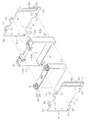
- the end plates 23 and 24 have a rectangular flat plate-like base portion 61 and four bolt insertion portions 62 protruding from the base portion 61.
- the bolt insertion portion 62 is provided with an insertion hole 67 that penetrates in the thickness direction of the end plates 23 and 24.
- the base portion 61 includes a rectangular flat plate-like facing portion 63 and a rectangular flat plate-shaped protruding portion 64 provided at the first longitudinal end of the facing portion 63.
- the protrusion 64 has a through hole 66 that penetrates in the thickness direction.
- the protrusion 64 includes an opening edge 68 that forms the through hole 66.
- the through hole 66 of the present embodiment is a long hole extending in the longitudinal direction of the protruding portion 64, that is, in the short direction of the base portion 61.
- the longitudinal dimension of the base 61 is larger than the width of the battery holder 40. That is, the dimension in the longitudinal direction of the base 61 is larger than the dimension from the outer surface of the second covering portion 42 to the outer surface of the third covering portion 43. More specifically, the dimension in the longitudinal direction of the base 61 is such that the thickness of the third cover 43 is determined from the opposite surface of the battery holder 40 in the thickness direction of the second cover 42 on the side opposite to the housing S. It is longer than the dimension to the surface on the opposite side to the accommodating part S among both surfaces.
- the second longitudinal end 61 a of the base 61 (the end opposite to the protruding portion 64) and the third covering portion 43 of the battery holder 40 face each other in the direction in which the battery cells 25 are juxtaposed.
- the battery body 22 and the end plates 23 and 24 are assembled.
- a part of the base part 61 faces the battery body 22, and the other part protrudes in the longitudinal direction of the base part 61 from the second covering part 42.
- a portion facing the battery body 22 is a facing portion 63
- a portion protruding in the longitudinal direction of the base portion 61 from the second covering portion 42 is a protruding portion 64.
- the two end plates 23 and 24 sandwich the battery body 22.
- the bolt B ⁇ b> 1 is inserted from the insertion hole 67 of one end plate 23 toward the other end plate 24.
- the bolt B1 is screwed into the nut N1 at a position where the bolt B1 is inserted through the insertion hole 67 of the end plate 24.
- the end plates 23 and 24 restrain the battery body 22.
- the battery module 21 is configured.
- the harness 54 connected to each connection terminal 51 is attached to the protruding portion 64 by a fixture 56.
- the fixture 56 is, for example, a metal wire.
- the fixture 56 binds the harness 54 to the opening edge 68 of the protrusion 64. More specifically, in the attachment 56, the harness 54 is attached to a portion of the opening edge portion 68 of the projecting portion 64 on the opposite side of the facing portion 63 with respect to the through hole 66 with a metal wire. . Therefore, the opening edge portion 68 that forms the through hole 66 corresponds to the attachment portion of the protruding portion 64.
- the battery module 21 described above is fixed to the housing 11 by brackets 71 provided on the end plates 23 and 24.
- a bracket 71 provided in the battery module 21 is fixed to the housing 11 by a bolt B2.
- the battery module 21 is fixed to the inner surface (the bottom portion of the main body 12) facing the lid member 13 among the inner surface 11 a of the housing 11.
- the protruding portions 64 of the end plates 23 and 24 protrude toward the inner surface 13 a of the lid member 13 from the battery body 22.
- the inner surface 11 a of the housing 11 includes an inner surface 12 b of the main body 12 and an inner surface 13 a of the lid member 13.
- the inner surface 13 a of the lid member 13 can also be said to be a surface that faces the protruding portion 64 on the inner surface 11 a of the housing 11 and intersects the protruding direction of the protruding portion 64.
- the protruding portion 64 protrudes in a direction away from the inner surface 11a of the housing 11 to which the battery module 21 is fixed.
- the shortest distance between the protrusion 64 and the inner surface 13a of the lid member 13 is shorter than the shortest distance between the battery body 22 and the inner surface 13a of the lid member 13. That is, in other words, the shortest distance between the protruding portion 64 and the surface 13 a that faces the protruding portion 64 and intersects the protruding direction of the protruding portion 64 in the inner surface 11 a of the housing 11 is the battery body 22 and the inner surface of the housing 11. In 11a, the distance is shorter than the shortest distance between the surface 13a facing the protrusion 64 and intersecting the protrusion direction of the protrusion 64.
- the protrusion 64 is configured.
- connection surface 53 a of the output portion 53 of the connection terminal 51 faces the inner surface 13 a of the lid member 13.
- the battery pack 10 of this embodiment is mounted on a vehicle, for example. As the vehicle travels, vibration and impact are applied to the battery pack 10. At this time, when the distance between the battery module 21 and the inner surface 11a of the housing 11 is small, or when the bolt B2 that fixes the bracket 71 to the housing 11 is loosened due to vibration or impact, the battery module 21 is There is a risk of colliding with the inner surface 11a of the housing 11.
- the harness 54 is attached to the connection surface 53 a of the connection terminal 51, the harness 54 is attached from the opening 12 a of the housing 11 after the battery module 21 is accommodated in the main body 12. At this time, if the connection surface 53a of the connection terminal 51 faces the opening 12a, the harness 54 can be easily attached.
- connection surface 53 a of the connection terminal 51 faces the opening 12 a
- connection surface 53 a of the connection terminal 51 faces the lid member 13 after the lid member 13 is fixed to the main body 12. Therefore, when the battery module 21 collides with the lid member 13, the connection surface 53 a of the connection terminal 51 may collide with the lid member 13, and in this case, it may cause a short circuit.
- the projecting portions 64 of the end plates 23 and 24 projecting toward the lid member 13 collide with the inner surface 13 a of the lid member 13. Therefore, the battery body 22 is prevented from colliding with the lid member 13.
- connection surface 53 a of the connection terminal 51 may collide with the lid member 13 due to the protruding portion 64. Deterred. Therefore, a short circuit of the battery cell 25 can be suppressed.
- Protruding portions 64 are provided on the end plates 23 and 24. Therefore, when the battery module 21 collides with the inner surface 11 a of the housing 11, the projecting portion 64 can collide with the inner surface of the housing 11, that is, the inner surface 13 a of the lid member 13, thereby protecting the battery body 22.
- connection surface 53 a of the connection terminal 51 faces the inner surface 11 a of the housing 11, that is, the inner surface 13 a of the lid member 13, the output portion 53 is prevented from colliding with the lid member 13. . Therefore, a short circuit of the battery cell 25 can be suppressed.
- connection surface 53 a of the connection terminal 51 faces the inner surface 13 a of the lid member 13. Therefore, when performing the attachment work of the harness 54, it is easy to perform the work and the harness 54 can be attached easily.
- the end plates 23 and 24 are reduced in weight. Further, by providing the through hole 66 in the projecting portion 64, the end plates 23, 24 can be reduced in weight without lowering the restraining force by the end plates 23, 24 as compared with the case where the through hole 66 is provided in the base portion 61. Can do.
- the harness 54 may be damaged when the harness 54 collides with the inner surface 11a of the housing 11, that is, the inner surface 13a of the lid member 13, the movement of the harness 54 needs to be regulated. Since the projecting portion 64 is provided with the through hole 66, the harness 54 can be attached to the opening edge 68 that forms the through hole 66. Therefore, the movement of the harness 54 can be restricted using the protrusion 64.
- the through holes 66 of the end plates 23 and 24 are long holes. For this reason, the area occupied by the opening edge portion 68 forming the through hole 66 is increased, and the harness 54 can be firmly fixed.
- the protruding portion 64 may be used as a hanging device attaching portion for attaching the hanging device 81.
- the battery module 21 is accommodated in the main body 12 through the opening 12 a with the opening 12 a of the main body 12 facing upward in the vertical direction.
- the battery module 21 is accommodated in the main body 12 in a state of being hung by the hanger 81.
- the protrusion 64 is also used as a fishing gear attachment. it can.
- the through-hole 66 of the protrusion part 64 of the end plates 23 and 24 may be omitted.
- the surface of the protrusion 64 in the thickness direction may be a flat surface, or the protrusion 64 may be provided with a recess.
- the attachment part of the protrusion part 64 may be anything as long as the harness 54 can be attached to the protrusion part 64, and may be a protrusion protruding from the protrusion part 64.
- the connection surface 53 a of the connection terminal 51 may face the inner surface 12 b of the main body 12. In this case, it is preferable that the protruding portion 64 protrudes in the opposing direction of the connection surface 53a and the inner surface 12b of the main body 12.
- connection terminal 51 may be omitted, and the harness 54 may be directly fixed to the positive electrode terminal 30 and the negative electrode terminal 31 of the battery cell 25.
- the protrusion 64 is different from the inner surface 11a of the housing 11 facing the connection surface 53a of the connection terminal 51 in addition to the facing direction of the connection surface 53a of the connection terminal 51 and the inner surface 11a of the housing 11. You may protrude toward the inner surface 11a.
- the protruding portion 64 is a housing different from the inner surface 11a of the housing 11 facing the connection surface 53a of the connection terminal 51 instead of the facing direction of the connection surface 53a of the connection terminal 51 and the inner surface 11a of the housing 11. 11 may protrude toward the inner surface 11a. That is, the protrusion 64 may protrude in any direction.
- the protruding portion 64 may be protruded in a direction in which the battery module 21 can easily move.
- the slide of the battery module 21 between the side surfaces becomes larger than the vertical movement of the battery module 21 between the lower surface and the upper surface.
- the protrusion part 64 is provided so that it may protrude toward a side surface.
- connection terminal 51 may be changed.
- the number of battery cells 25 may be increased or decreased.
- the battery cells 25 may be connected in parallel.
- the protrusion 64 may be provided on only one of the two end plates 23 and 24 that sandwich the battery body 22.
- the bracket 71 may be fixed to the housing 11 with any fastening member other than the bolt B2.
- the end plates 23 and 24 and the bracket 71 may be integrally formed.
- the through hole 66 may be other than a long hole. In place of the through hole 66, a notch may be provided in the protruding portion 64.
- the battery body 22 may not have the battery holder 40.
- the harness 54 may be attached to the end plates 23 and 24 with an adhesive or the like.
- the number of battery modules 21 may be singular or plural.
Landscapes
- Chemical & Material Sciences (AREA)
- Chemical Kinetics & Catalysis (AREA)
- Electrochemistry (AREA)
- General Chemical & Material Sciences (AREA)
- Battery Mounting, Suspending (AREA)
- Connection Of Batteries Or Terminals (AREA)
Priority Applications (3)
| Application Number | Priority Date | Filing Date | Title |
|---|---|---|---|
| DE112015001140.4T DE112015001140T5 (de) | 2014-03-07 | 2015-02-16 | Batteriepackung |
| US15/117,886 US10056601B2 (en) | 2014-03-07 | 2015-02-16 | Battery pack |
| CN201580011205.2A CN106062993B (zh) | 2014-03-07 | 2015-02-16 | 电池组 |
Applications Claiming Priority (2)
| Application Number | Priority Date | Filing Date | Title |
|---|---|---|---|
| JP2014045209A JP6330379B2 (ja) | 2014-03-07 | 2014-03-07 | 電池パック |
| JP2014-045209 | 2014-03-07 |
Publications (1)
| Publication Number | Publication Date |
|---|---|
| WO2015133253A1 true WO2015133253A1 (ja) | 2015-09-11 |
Family
ID=54055063
Family Applications (1)
| Application Number | Title | Priority Date | Filing Date |
|---|---|---|---|
| PCT/JP2015/054149 Ceased WO2015133253A1 (ja) | 2014-03-07 | 2015-02-16 | 電池パック |
Country Status (5)
| Country | Link |
|---|---|
| US (1) | US10056601B2 (enExample) |
| JP (1) | JP6330379B2 (enExample) |
| CN (1) | CN106062993B (enExample) |
| DE (1) | DE112015001140T5 (enExample) |
| WO (1) | WO2015133253A1 (enExample) |
Families Citing this family (4)
| Publication number | Priority date | Publication date | Assignee | Title |
|---|---|---|---|---|
| JP6545212B2 (ja) * | 2017-03-17 | 2019-07-17 | 本田技研工業株式会社 | 電池パック |
| JP6922750B2 (ja) * | 2018-01-12 | 2021-08-18 | トヨタ自動車株式会社 | 蓄電装置 |
| KR102885825B1 (ko) * | 2020-04-14 | 2025-11-12 | 주식회사 엘지에너지솔루션 | 전지 모듈 및 이를 포함하는 전지팩 |
| JP7491198B2 (ja) * | 2020-11-30 | 2024-05-28 | トヨタ自動車株式会社 | 電池パック |
Citations (5)
| Publication number | Priority date | Publication date | Assignee | Title |
|---|---|---|---|---|
| JP2011129509A (ja) * | 2009-12-18 | 2011-06-30 | Sb Limotive Co Ltd | バッテリーモジュール及びバッテリーモジュールのリストレーナ固定方法 |
| EP2528137A1 (en) * | 2011-05-25 | 2012-11-28 | Sanyo Electric Co., Ltd. | Power source apparatus to supply electric power and vehicle equipped with the power source apparatus |
| JP2013114943A (ja) * | 2011-11-30 | 2013-06-10 | Mitsubishi Heavy Ind Ltd | 電池モジュール及び電池システム |
| JP2014017190A (ja) * | 2012-07-11 | 2014-01-30 | Yazaki Corp | 電気ユニットの取付構造 |
| WO2014065110A1 (ja) * | 2012-10-25 | 2014-05-01 | 日産自動車株式会社 | 電池モジュールのガス排出構造 |
Family Cites Families (10)
| Publication number | Priority date | Publication date | Assignee | Title |
|---|---|---|---|---|
| KR100612305B1 (ko) * | 2004-06-25 | 2006-08-11 | 삼성에스디아이 주식회사 | 전지 모듈 |
| US7960943B2 (en) * | 2006-11-17 | 2011-06-14 | Cobasys, Llc | Modular battery system having battery monitoring and data collection capability |
| JP5180505B2 (ja) | 2007-03-30 | 2013-04-10 | 三菱重工業株式会社 | 電池モジュール |
| JP2008277058A (ja) * | 2007-04-26 | 2008-11-13 | Toyota Motor Corp | 電源装置 |
| WO2010113455A1 (ja) * | 2009-03-31 | 2010-10-07 | 三洋電機株式会社 | 電池モジュール、バッテリシステムおよび電動車両 |
| EP2325922B1 (en) | 2009-11-19 | 2012-05-09 | SB LiMotive Co., Ltd. | Battery pack |
| CN102117930B (zh) * | 2010-01-05 | 2015-09-16 | 三星Sdi株式会社 | 电池组 |
| US20110165451A1 (en) | 2010-01-05 | 2011-07-07 | Myung-Chul Kim | Battery pack |
| CN102959761A (zh) * | 2010-06-30 | 2013-03-06 | 松下电器产业株式会社 | 电池模块 |
| US8771864B2 (en) | 2011-02-23 | 2014-07-08 | Samsung Sdi Co., Ltd. | Battery module |
-
2014
- 2014-03-07 JP JP2014045209A patent/JP6330379B2/ja not_active Expired - Fee Related
-
2015
- 2015-02-16 WO PCT/JP2015/054149 patent/WO2015133253A1/ja not_active Ceased
- 2015-02-16 US US15/117,886 patent/US10056601B2/en not_active Expired - Fee Related
- 2015-02-16 DE DE112015001140.4T patent/DE112015001140T5/de not_active Withdrawn
- 2015-02-16 CN CN201580011205.2A patent/CN106062993B/zh not_active Expired - Fee Related
Patent Citations (5)
| Publication number | Priority date | Publication date | Assignee | Title |
|---|---|---|---|---|
| JP2011129509A (ja) * | 2009-12-18 | 2011-06-30 | Sb Limotive Co Ltd | バッテリーモジュール及びバッテリーモジュールのリストレーナ固定方法 |
| EP2528137A1 (en) * | 2011-05-25 | 2012-11-28 | Sanyo Electric Co., Ltd. | Power source apparatus to supply electric power and vehicle equipped with the power source apparatus |
| JP2013114943A (ja) * | 2011-11-30 | 2013-06-10 | Mitsubishi Heavy Ind Ltd | 電池モジュール及び電池システム |
| JP2014017190A (ja) * | 2012-07-11 | 2014-01-30 | Yazaki Corp | 電気ユニットの取付構造 |
| WO2014065110A1 (ja) * | 2012-10-25 | 2014-05-01 | 日産自動車株式会社 | 電池モジュールのガス排出構造 |
Also Published As
| Publication number | Publication date |
|---|---|
| US20170012276A1 (en) | 2017-01-12 |
| US10056601B2 (en) | 2018-08-21 |
| CN106062993B (zh) | 2019-10-01 |
| DE112015001140T5 (de) | 2016-12-22 |
| JP6330379B2 (ja) | 2018-05-30 |
| JP2015170510A (ja) | 2015-09-28 |
| CN106062993A (zh) | 2016-10-26 |
Similar Documents
| Publication | Publication Date | Title |
|---|---|---|
| CN108630851B (zh) | 电池组 | |
| JP6390721B2 (ja) | 電池パック | |
| JP6206308B2 (ja) | 電池パック | |
| JP6409345B2 (ja) | 電池モジュール及び電池パック | |
| EP2927990A2 (en) | Energy storage apparatus | |
| CN106663765B (zh) | 电池模块 | |
| WO2015133253A1 (ja) | 電池パック | |
| JP6318862B2 (ja) | 電池モジュール及び電池パック | |
| JP6609989B2 (ja) | 電池モジュール | |
| JP6465354B2 (ja) | 蓄電モジュール | |
| KR20190122825A (ko) | 전지 모듈 및 축전 유닛 | |
| JPWO2017022068A1 (ja) | 電子機器の筐体の組付け構造及び電子機器 | |
| JP6508345B2 (ja) | 端子及び配線モジュール | |
| KR20140118759A (ko) | 축전 장치 | |
| JP5189518B2 (ja) | カーテンウォール固定用ブラケット及びカーテンウォール | |
| JP7243561B2 (ja) | 電池パック | |
| JP2013143333A5 (enExample) | ||
| CN107836051A (zh) | 布线模块 | |
| KR101790917B1 (ko) | 반장치용 케이스 | |
| JP6794709B2 (ja) | 電池モジュール | |
| JP6390722B2 (ja) | 電池パック | |
| JP6540355B2 (ja) | 電池パック | |
| JP6565585B2 (ja) | 電池パック | |
| JP5826312B2 (ja) | 筐体取付け構造及びそれに用いられる取付け具 | |
| JP6044405B2 (ja) | 電池パック及び電池モジュールの組み付け方法 |
Legal Events
| Date | Code | Title | Description |
|---|---|---|---|
| 121 | Ep: the epo has been informed by wipo that ep was designated in this application |
Ref document number: 15758857 Country of ref document: EP Kind code of ref document: A1 |
|
| WWE | Wipo information: entry into national phase |
Ref document number: 15117886 Country of ref document: US |
|
| NENP | Non-entry into the national phase |
Ref country code: DE |
|
| WWE | Wipo information: entry into national phase |
Ref document number: 112015001140 Country of ref document: DE |
|
| 122 | Ep: pct application non-entry in european phase |
Ref document number: 15758857 Country of ref document: EP Kind code of ref document: A1 |