WO2015129672A1 - 液晶表示装置 - Google Patents
液晶表示装置 Download PDFInfo
- Publication number
- WO2015129672A1 WO2015129672A1 PCT/JP2015/055172 JP2015055172W WO2015129672A1 WO 2015129672 A1 WO2015129672 A1 WO 2015129672A1 JP 2015055172 W JP2015055172 W JP 2015055172W WO 2015129672 A1 WO2015129672 A1 WO 2015129672A1
- Authority
- WO
- WIPO (PCT)
- Prior art keywords
- group
- liquid crystal
- carbon atoms
- crystal display
- general formula
- Prior art date
Links
- 0 C=CC(C*OC(CCC(Oc1cc(cccc2)c2cc1)=O)=O)=O Chemical compound C=CC(C*OC(CCC(Oc1cc(cccc2)c2cc1)=O)=O)=O 0.000 description 2
- QGWANSPWXARJDD-UHFFFAOYSA-N CCC(C)(C)C(Oc(cc1)cc(O2)c1C=CC2=O)=O Chemical compound CCC(C)(C)C(Oc(cc1)cc(O2)c1C=CC2=O)=O QGWANSPWXARJDD-UHFFFAOYSA-N 0.000 description 1
- BWIYRDCFOWTYRT-UHFFFAOYSA-N CCCC(Oc(cc1)cc(cc2)c1cc2C(Oc(cc1)cc(NC(C=C)=O)c1OC=O)=O)=O Chemical compound CCCC(Oc(cc1)cc(cc2)c1cc2C(Oc(cc1)cc(NC(C=C)=O)c1OC=O)=O)=O BWIYRDCFOWTYRT-UHFFFAOYSA-N 0.000 description 1
- CVJQAURDKGNVBN-UHFFFAOYSA-N COc(cc1)ccc1C(Oc1cc(C(O)=O)cc(OC(c(cc2)ccc2O)=O)c1)=O Chemical compound COc(cc1)ccc1C(Oc1cc(C(O)=O)cc(OC(c(cc2)ccc2O)=O)c1)=O CVJQAURDKGNVBN-UHFFFAOYSA-N 0.000 description 1
Images


Classifications
-
- C—CHEMISTRY; METALLURGY
- C09—DYES; PAINTS; POLISHES; NATURAL RESINS; ADHESIVES; COMPOSITIONS NOT OTHERWISE PROVIDED FOR; APPLICATIONS OF MATERIALS NOT OTHERWISE PROVIDED FOR
- C09K—MATERIALS FOR MISCELLANEOUS APPLICATIONS, NOT PROVIDED FOR ELSEWHERE
- C09K19/00—Liquid crystal materials
- C09K19/04—Liquid crystal materials characterised by the chemical structure of the liquid crystal components, e.g. by a specific unit
- C09K19/42—Mixtures of liquid crystal compounds covered by two or more of the preceding groups C09K19/06 - C09K19/40
-
- C—CHEMISTRY; METALLURGY
- C09—DYES; PAINTS; POLISHES; NATURAL RESINS; ADHESIVES; COMPOSITIONS NOT OTHERWISE PROVIDED FOR; APPLICATIONS OF MATERIALS NOT OTHERWISE PROVIDED FOR
- C09K—MATERIALS FOR MISCELLANEOUS APPLICATIONS, NOT PROVIDED FOR ELSEWHERE
- C09K19/00—Liquid crystal materials
- C09K19/04—Liquid crystal materials characterised by the chemical structure of the liquid crystal components, e.g. by a specific unit
- C09K19/06—Non-steroidal liquid crystal compounds
- C09K19/08—Non-steroidal liquid crystal compounds containing at least two non-condensed rings
- C09K19/10—Non-steroidal liquid crystal compounds containing at least two non-condensed rings containing at least two benzene rings
- C09K19/24—Non-steroidal liquid crystal compounds containing at least two non-condensed rings containing at least two benzene rings linked by a chain containing nitrogen-to-nitrogen bonds
-
- C—CHEMISTRY; METALLURGY
- C09—DYES; PAINTS; POLISHES; NATURAL RESINS; ADHESIVES; COMPOSITIONS NOT OTHERWISE PROVIDED FOR; APPLICATIONS OF MATERIALS NOT OTHERWISE PROVIDED FOR
- C09K—MATERIALS FOR MISCELLANEOUS APPLICATIONS, NOT PROVIDED FOR ELSEWHERE
- C09K19/00—Liquid crystal materials
- C09K19/04—Liquid crystal materials characterised by the chemical structure of the liquid crystal components, e.g. by a specific unit
- C09K19/06—Non-steroidal liquid crystal compounds
- C09K19/08—Non-steroidal liquid crystal compounds containing at least two non-condensed rings
- C09K19/30—Non-steroidal liquid crystal compounds containing at least two non-condensed rings containing saturated or unsaturated non-aromatic rings, e.g. cyclohexane rings
- C09K19/3001—Cyclohexane rings
- C09K19/3003—Compounds containing at least two rings in which the different rings are directly linked (covalent bond)
-
- C—CHEMISTRY; METALLURGY
- C09—DYES; PAINTS; POLISHES; NATURAL RESINS; ADHESIVES; COMPOSITIONS NOT OTHERWISE PROVIDED FOR; APPLICATIONS OF MATERIALS NOT OTHERWISE PROVIDED FOR
- C09K—MATERIALS FOR MISCELLANEOUS APPLICATIONS, NOT PROVIDED FOR ELSEWHERE
- C09K19/00—Liquid crystal materials
- C09K19/04—Liquid crystal materials characterised by the chemical structure of the liquid crystal components, e.g. by a specific unit
- C09K19/06—Non-steroidal liquid crystal compounds
- C09K19/08—Non-steroidal liquid crystal compounds containing at least two non-condensed rings
- C09K19/30—Non-steroidal liquid crystal compounds containing at least two non-condensed rings containing saturated or unsaturated non-aromatic rings, e.g. cyclohexane rings
- C09K19/3001—Cyclohexane rings
- C09K19/3066—Cyclohexane rings in which the rings are linked by a chain containing carbon and oxygen atoms, e.g. esters or ethers
-
- C—CHEMISTRY; METALLURGY
- C09—DYES; PAINTS; POLISHES; NATURAL RESINS; ADHESIVES; COMPOSITIONS NOT OTHERWISE PROVIDED FOR; APPLICATIONS OF MATERIALS NOT OTHERWISE PROVIDED FOR
- C09K—MATERIALS FOR MISCELLANEOUS APPLICATIONS, NOT PROVIDED FOR ELSEWHERE
- C09K19/00—Liquid crystal materials
- C09K19/04—Liquid crystal materials characterised by the chemical structure of the liquid crystal components, e.g. by a specific unit
- C09K19/06—Non-steroidal liquid crystal compounds
- C09K19/32—Non-steroidal liquid crystal compounds containing condensed ring systems, i.e. fused, bridged or spiro ring systems
- C09K19/322—Compounds containing a naphthalene ring or a completely or partially hydrogenated naphthalene ring
-
- C—CHEMISTRY; METALLURGY
- C09—DYES; PAINTS; POLISHES; NATURAL RESINS; ADHESIVES; COMPOSITIONS NOT OTHERWISE PROVIDED FOR; APPLICATIONS OF MATERIALS NOT OTHERWISE PROVIDED FOR
- C09K—MATERIALS FOR MISCELLANEOUS APPLICATIONS, NOT PROVIDED FOR ELSEWHERE
- C09K19/00—Liquid crystal materials
- C09K19/04—Liquid crystal materials characterised by the chemical structure of the liquid crystal components, e.g. by a specific unit
- C09K19/38—Polymers
- C09K19/3804—Polymers with mesogenic groups in the main chain
- C09K19/3814—Polyethers
-
- C—CHEMISTRY; METALLURGY
- C09—DYES; PAINTS; POLISHES; NATURAL RESINS; ADHESIVES; COMPOSITIONS NOT OTHERWISE PROVIDED FOR; APPLICATIONS OF MATERIALS NOT OTHERWISE PROVIDED FOR
- C09K—MATERIALS FOR MISCELLANEOUS APPLICATIONS, NOT PROVIDED FOR ELSEWHERE
- C09K19/00—Liquid crystal materials
- C09K19/04—Liquid crystal materials characterised by the chemical structure of the liquid crystal components, e.g. by a specific unit
- C09K19/42—Mixtures of liquid crystal compounds covered by two or more of the preceding groups C09K19/06 - C09K19/40
- C09K19/44—Mixtures of liquid crystal compounds covered by two or more of the preceding groups C09K19/06 - C09K19/40 containing compounds with benzene rings directly linked
-
- C—CHEMISTRY; METALLURGY
- C09—DYES; PAINTS; POLISHES; NATURAL RESINS; ADHESIVES; COMPOSITIONS NOT OTHERWISE PROVIDED FOR; APPLICATIONS OF MATERIALS NOT OTHERWISE PROVIDED FOR
- C09K—MATERIALS FOR MISCELLANEOUS APPLICATIONS, NOT PROVIDED FOR ELSEWHERE
- C09K19/00—Liquid crystal materials
- C09K19/04—Liquid crystal materials characterised by the chemical structure of the liquid crystal components, e.g. by a specific unit
- C09K19/42—Mixtures of liquid crystal compounds covered by two or more of the preceding groups C09K19/06 - C09K19/40
- C09K19/46—Mixtures of liquid crystal compounds covered by two or more of the preceding groups C09K19/06 - C09K19/40 containing esters
-
- C—CHEMISTRY; METALLURGY
- C09—DYES; PAINTS; POLISHES; NATURAL RESINS; ADHESIVES; COMPOSITIONS NOT OTHERWISE PROVIDED FOR; APPLICATIONS OF MATERIALS NOT OTHERWISE PROVIDED FOR
- C09K—MATERIALS FOR MISCELLANEOUS APPLICATIONS, NOT PROVIDED FOR ELSEWHERE
- C09K19/00—Liquid crystal materials
- C09K19/52—Liquid crystal materials characterised by components which are not liquid crystals, e.g. additives with special physical aspect: solvents, solid particles
- C09K19/54—Additives having no specific mesophase characterised by their chemical composition
-
- G—PHYSICS
- G02—OPTICS
- G02B—OPTICAL ELEMENTS, SYSTEMS OR APPARATUS
- G02B5/00—Optical elements other than lenses
- G02B5/30—Polarising elements
- G02B5/3016—Polarising elements involving passive liquid crystal elements
-
- G—PHYSICS
- G02—OPTICS
- G02F—OPTICAL DEVICES OR ARRANGEMENTS FOR THE CONTROL OF LIGHT BY MODIFICATION OF THE OPTICAL PROPERTIES OF THE MEDIA OF THE ELEMENTS INVOLVED THEREIN; NON-LINEAR OPTICS; FREQUENCY-CHANGING OF LIGHT; OPTICAL LOGIC ELEMENTS; OPTICAL ANALOGUE/DIGITAL CONVERTERS
- G02F1/00—Devices or arrangements for the control of the intensity, colour, phase, polarisation or direction of light arriving from an independent light source, e.g. switching, gating or modulating; Non-linear optics
- G02F1/01—Devices or arrangements for the control of the intensity, colour, phase, polarisation or direction of light arriving from an independent light source, e.g. switching, gating or modulating; Non-linear optics for the control of the intensity, phase, polarisation or colour
- G02F1/13—Devices or arrangements for the control of the intensity, colour, phase, polarisation or direction of light arriving from an independent light source, e.g. switching, gating or modulating; Non-linear optics for the control of the intensity, phase, polarisation or colour based on liquid crystals, e.g. single liquid crystal display cells
- G02F1/133—Constructional arrangements; Operation of liquid crystal cells; Circuit arrangements
- G02F1/1333—Constructional arrangements; Manufacturing methods
- G02F1/1335—Structural association of cells with optical devices, e.g. polarisers or reflectors
- G02F1/13363—Birefringent elements, e.g. for optical compensation
-
- G—PHYSICS
- G02—OPTICS
- G02F—OPTICAL DEVICES OR ARRANGEMENTS FOR THE CONTROL OF LIGHT BY MODIFICATION OF THE OPTICAL PROPERTIES OF THE MEDIA OF THE ELEMENTS INVOLVED THEREIN; NON-LINEAR OPTICS; FREQUENCY-CHANGING OF LIGHT; OPTICAL LOGIC ELEMENTS; OPTICAL ANALOGUE/DIGITAL CONVERTERS
- G02F1/00—Devices or arrangements for the control of the intensity, colour, phase, polarisation or direction of light arriving from an independent light source, e.g. switching, gating or modulating; Non-linear optics
- G02F1/01—Devices or arrangements for the control of the intensity, colour, phase, polarisation or direction of light arriving from an independent light source, e.g. switching, gating or modulating; Non-linear optics for the control of the intensity, phase, polarisation or colour
- G02F1/13—Devices or arrangements for the control of the intensity, colour, phase, polarisation or direction of light arriving from an independent light source, e.g. switching, gating or modulating; Non-linear optics for the control of the intensity, phase, polarisation or colour based on liquid crystals, e.g. single liquid crystal display cells
- G02F1/137—Devices or arrangements for the control of the intensity, colour, phase, polarisation or direction of light arriving from an independent light source, e.g. switching, gating or modulating; Non-linear optics for the control of the intensity, phase, polarisation or colour based on liquid crystals, e.g. single liquid crystal display cells characterised by the electro-optical or magneto-optical effect, e.g. field-induced phase transition, orientation effect, guest-host interaction or dynamic scattering
- G02F1/139—Devices or arrangements for the control of the intensity, colour, phase, polarisation or direction of light arriving from an independent light source, e.g. switching, gating or modulating; Non-linear optics for the control of the intensity, phase, polarisation or colour based on liquid crystals, e.g. single liquid crystal display cells characterised by the electro-optical or magneto-optical effect, e.g. field-induced phase transition, orientation effect, guest-host interaction or dynamic scattering based on orientation effects in which the liquid crystal remains transparent
- G02F1/1393—Devices or arrangements for the control of the intensity, colour, phase, polarisation or direction of light arriving from an independent light source, e.g. switching, gating or modulating; Non-linear optics for the control of the intensity, phase, polarisation or colour based on liquid crystals, e.g. single liquid crystal display cells characterised by the electro-optical or magneto-optical effect, e.g. field-induced phase transition, orientation effect, guest-host interaction or dynamic scattering based on orientation effects in which the liquid crystal remains transparent the birefringence of the liquid crystal being electrically controlled, e.g. ECB-, DAP-, HAN-, PI-LC cells
-
- C—CHEMISTRY; METALLURGY
- C09—DYES; PAINTS; POLISHES; NATURAL RESINS; ADHESIVES; COMPOSITIONS NOT OTHERWISE PROVIDED FOR; APPLICATIONS OF MATERIALS NOT OTHERWISE PROVIDED FOR
- C09K—MATERIALS FOR MISCELLANEOUS APPLICATIONS, NOT PROVIDED FOR ELSEWHERE
- C09K19/00—Liquid crystal materials
- C09K19/04—Liquid crystal materials characterised by the chemical structure of the liquid crystal components, e.g. by a specific unit
- C09K2019/0444—Liquid crystal materials characterised by the chemical structure of the liquid crystal components, e.g. by a specific unit characterized by a linking chain between rings or ring systems, a bridging chain between extensive mesogenic moieties or an end chain group
- C09K2019/0448—Liquid crystal materials characterised by the chemical structure of the liquid crystal components, e.g. by a specific unit characterized by a linking chain between rings or ring systems, a bridging chain between extensive mesogenic moieties or an end chain group the end chain group being a polymerizable end group, e.g. -Sp-P or acrylate
-
- C—CHEMISTRY; METALLURGY
- C09—DYES; PAINTS; POLISHES; NATURAL RESINS; ADHESIVES; COMPOSITIONS NOT OTHERWISE PROVIDED FOR; APPLICATIONS OF MATERIALS NOT OTHERWISE PROVIDED FOR
- C09K—MATERIALS FOR MISCELLANEOUS APPLICATIONS, NOT PROVIDED FOR ELSEWHERE
- C09K19/00—Liquid crystal materials
- C09K19/04—Liquid crystal materials characterised by the chemical structure of the liquid crystal components, e.g. by a specific unit
- C09K2019/0444—Liquid crystal materials characterised by the chemical structure of the liquid crystal components, e.g. by a specific unit characterized by a linking chain between rings or ring systems, a bridging chain between extensive mesogenic moieties or an end chain group
- C09K2019/0466—Liquid crystal materials characterised by the chemical structure of the liquid crystal components, e.g. by a specific unit characterized by a linking chain between rings or ring systems, a bridging chain between extensive mesogenic moieties or an end chain group the linking chain being a -CF2O- chain
-
- C—CHEMISTRY; METALLURGY
- C09—DYES; PAINTS; POLISHES; NATURAL RESINS; ADHESIVES; COMPOSITIONS NOT OTHERWISE PROVIDED FOR; APPLICATIONS OF MATERIALS NOT OTHERWISE PROVIDED FOR
- C09K—MATERIALS FOR MISCELLANEOUS APPLICATIONS, NOT PROVIDED FOR ELSEWHERE
- C09K19/00—Liquid crystal materials
- C09K19/04—Liquid crystal materials characterised by the chemical structure of the liquid crystal components, e.g. by a specific unit
- C09K19/06—Non-steroidal liquid crystal compounds
- C09K19/08—Non-steroidal liquid crystal compounds containing at least two non-condensed rings
- C09K19/10—Non-steroidal liquid crystal compounds containing at least two non-condensed rings containing at least two benzene rings
- C09K19/12—Non-steroidal liquid crystal compounds containing at least two non-condensed rings containing at least two benzene rings at least two benzene rings directly linked, e.g. biphenyls
- C09K2019/121—Compounds containing phenylene-1,4-diyl (-Ph-)
- C09K2019/122—Ph-Ph
-
- C—CHEMISTRY; METALLURGY
- C09—DYES; PAINTS; POLISHES; NATURAL RESINS; ADHESIVES; COMPOSITIONS NOT OTHERWISE PROVIDED FOR; APPLICATIONS OF MATERIALS NOT OTHERWISE PROVIDED FOR
- C09K—MATERIALS FOR MISCELLANEOUS APPLICATIONS, NOT PROVIDED FOR ELSEWHERE
- C09K19/00—Liquid crystal materials
- C09K19/04—Liquid crystal materials characterised by the chemical structure of the liquid crystal components, e.g. by a specific unit
- C09K19/06—Non-steroidal liquid crystal compounds
- C09K19/08—Non-steroidal liquid crystal compounds containing at least two non-condensed rings
- C09K19/10—Non-steroidal liquid crystal compounds containing at least two non-condensed rings containing at least two benzene rings
- C09K19/12—Non-steroidal liquid crystal compounds containing at least two non-condensed rings containing at least two benzene rings at least two benzene rings directly linked, e.g. biphenyls
- C09K2019/121—Compounds containing phenylene-1,4-diyl (-Ph-)
- C09K2019/123—Ph-Ph-Ph
-
- C—CHEMISTRY; METALLURGY
- C09—DYES; PAINTS; POLISHES; NATURAL RESINS; ADHESIVES; COMPOSITIONS NOT OTHERWISE PROVIDED FOR; APPLICATIONS OF MATERIALS NOT OTHERWISE PROVIDED FOR
- C09K—MATERIALS FOR MISCELLANEOUS APPLICATIONS, NOT PROVIDED FOR ELSEWHERE
- C09K19/00—Liquid crystal materials
- C09K19/04—Liquid crystal materials characterised by the chemical structure of the liquid crystal components, e.g. by a specific unit
- C09K19/06—Non-steroidal liquid crystal compounds
- C09K19/08—Non-steroidal liquid crystal compounds containing at least two non-condensed rings
- C09K19/10—Non-steroidal liquid crystal compounds containing at least two non-condensed rings containing at least two benzene rings
- C09K19/20—Non-steroidal liquid crystal compounds containing at least two non-condensed rings containing at least two benzene rings linked by a chain containing carbon and oxygen atoms as chain links, e.g. esters or ethers
- C09K19/2007—Non-steroidal liquid crystal compounds containing at least two non-condensed rings containing at least two benzene rings linked by a chain containing carbon and oxygen atoms as chain links, e.g. esters or ethers the chain containing -COO- or -OCO- groups
- C09K2019/2042—Ph-Ph-COO-Ph
-
- C—CHEMISTRY; METALLURGY
- C09—DYES; PAINTS; POLISHES; NATURAL RESINS; ADHESIVES; COMPOSITIONS NOT OTHERWISE PROVIDED FOR; APPLICATIONS OF MATERIALS NOT OTHERWISE PROVIDED FOR
- C09K—MATERIALS FOR MISCELLANEOUS APPLICATIONS, NOT PROVIDED FOR ELSEWHERE
- C09K19/00—Liquid crystal materials
- C09K19/04—Liquid crystal materials characterised by the chemical structure of the liquid crystal components, e.g. by a specific unit
- C09K19/06—Non-steroidal liquid crystal compounds
- C09K19/08—Non-steroidal liquid crystal compounds containing at least two non-condensed rings
- C09K19/10—Non-steroidal liquid crystal compounds containing at least two non-condensed rings containing at least two benzene rings
- C09K19/20—Non-steroidal liquid crystal compounds containing at least two non-condensed rings containing at least two benzene rings linked by a chain containing carbon and oxygen atoms as chain links, e.g. esters or ethers
- C09K19/2007—Non-steroidal liquid crystal compounds containing at least two non-condensed rings containing at least two benzene rings linked by a chain containing carbon and oxygen atoms as chain links, e.g. esters or ethers the chain containing -COO- or -OCO- groups
- C09K2019/2078—Ph-COO-Ph-COO-Ph
-
- C—CHEMISTRY; METALLURGY
- C09—DYES; PAINTS; POLISHES; NATURAL RESINS; ADHESIVES; COMPOSITIONS NOT OTHERWISE PROVIDED FOR; APPLICATIONS OF MATERIALS NOT OTHERWISE PROVIDED FOR
- C09K—MATERIALS FOR MISCELLANEOUS APPLICATIONS, NOT PROVIDED FOR ELSEWHERE
- C09K19/00—Liquid crystal materials
- C09K19/04—Liquid crystal materials characterised by the chemical structure of the liquid crystal components, e.g. by a specific unit
- C09K19/06—Non-steroidal liquid crystal compounds
- C09K19/08—Non-steroidal liquid crystal compounds containing at least two non-condensed rings
- C09K19/30—Non-steroidal liquid crystal compounds containing at least two non-condensed rings containing saturated or unsaturated non-aromatic rings, e.g. cyclohexane rings
- C09K19/3001—Cyclohexane rings
- C09K19/3003—Compounds containing at least two rings in which the different rings are directly linked (covalent bond)
- C09K2019/3004—Cy-Cy
-
- C—CHEMISTRY; METALLURGY
- C09—DYES; PAINTS; POLISHES; NATURAL RESINS; ADHESIVES; COMPOSITIONS NOT OTHERWISE PROVIDED FOR; APPLICATIONS OF MATERIALS NOT OTHERWISE PROVIDED FOR
- C09K—MATERIALS FOR MISCELLANEOUS APPLICATIONS, NOT PROVIDED FOR ELSEWHERE
- C09K19/00—Liquid crystal materials
- C09K19/04—Liquid crystal materials characterised by the chemical structure of the liquid crystal components, e.g. by a specific unit
- C09K19/06—Non-steroidal liquid crystal compounds
- C09K19/08—Non-steroidal liquid crystal compounds containing at least two non-condensed rings
- C09K19/30—Non-steroidal liquid crystal compounds containing at least two non-condensed rings containing saturated or unsaturated non-aromatic rings, e.g. cyclohexane rings
- C09K19/3001—Cyclohexane rings
- C09K19/3003—Compounds containing at least two rings in which the different rings are directly linked (covalent bond)
- C09K2019/3009—Cy-Ph
-
- C—CHEMISTRY; METALLURGY
- C09—DYES; PAINTS; POLISHES; NATURAL RESINS; ADHESIVES; COMPOSITIONS NOT OTHERWISE PROVIDED FOR; APPLICATIONS OF MATERIALS NOT OTHERWISE PROVIDED FOR
- C09K—MATERIALS FOR MISCELLANEOUS APPLICATIONS, NOT PROVIDED FOR ELSEWHERE
- C09K19/00—Liquid crystal materials
- C09K19/04—Liquid crystal materials characterised by the chemical structure of the liquid crystal components, e.g. by a specific unit
- C09K19/06—Non-steroidal liquid crystal compounds
- C09K19/08—Non-steroidal liquid crystal compounds containing at least two non-condensed rings
- C09K19/30—Non-steroidal liquid crystal compounds containing at least two non-condensed rings containing saturated or unsaturated non-aromatic rings, e.g. cyclohexane rings
- C09K19/3001—Cyclohexane rings
- C09K19/3003—Compounds containing at least two rings in which the different rings are directly linked (covalent bond)
- C09K2019/301—Cy-Cy-Ph
-
- C—CHEMISTRY; METALLURGY
- C09—DYES; PAINTS; POLISHES; NATURAL RESINS; ADHESIVES; COMPOSITIONS NOT OTHERWISE PROVIDED FOR; APPLICATIONS OF MATERIALS NOT OTHERWISE PROVIDED FOR
- C09K—MATERIALS FOR MISCELLANEOUS APPLICATIONS, NOT PROVIDED FOR ELSEWHERE
- C09K19/00—Liquid crystal materials
- C09K19/04—Liquid crystal materials characterised by the chemical structure of the liquid crystal components, e.g. by a specific unit
- C09K19/06—Non-steroidal liquid crystal compounds
- C09K19/08—Non-steroidal liquid crystal compounds containing at least two non-condensed rings
- C09K19/30—Non-steroidal liquid crystal compounds containing at least two non-condensed rings containing saturated or unsaturated non-aromatic rings, e.g. cyclohexane rings
- C09K19/3001—Cyclohexane rings
- C09K19/3003—Compounds containing at least two rings in which the different rings are directly linked (covalent bond)
- C09K2019/3013—Cy-Ph-Cy
-
- C—CHEMISTRY; METALLURGY
- C09—DYES; PAINTS; POLISHES; NATURAL RESINS; ADHESIVES; COMPOSITIONS NOT OTHERWISE PROVIDED FOR; APPLICATIONS OF MATERIALS NOT OTHERWISE PROVIDED FOR
- C09K—MATERIALS FOR MISCELLANEOUS APPLICATIONS, NOT PROVIDED FOR ELSEWHERE
- C09K19/00—Liquid crystal materials
- C09K19/04—Liquid crystal materials characterised by the chemical structure of the liquid crystal components, e.g. by a specific unit
- C09K19/06—Non-steroidal liquid crystal compounds
- C09K19/08—Non-steroidal liquid crystal compounds containing at least two non-condensed rings
- C09K19/30—Non-steroidal liquid crystal compounds containing at least two non-condensed rings containing saturated or unsaturated non-aromatic rings, e.g. cyclohexane rings
- C09K19/3001—Cyclohexane rings
- C09K19/3003—Compounds containing at least two rings in which the different rings are directly linked (covalent bond)
- C09K2019/3016—Cy-Ph-Ph
-
- C—CHEMISTRY; METALLURGY
- C09—DYES; PAINTS; POLISHES; NATURAL RESINS; ADHESIVES; COMPOSITIONS NOT OTHERWISE PROVIDED FOR; APPLICATIONS OF MATERIALS NOT OTHERWISE PROVIDED FOR
- C09K—MATERIALS FOR MISCELLANEOUS APPLICATIONS, NOT PROVIDED FOR ELSEWHERE
- C09K19/00—Liquid crystal materials
- C09K19/04—Liquid crystal materials characterised by the chemical structure of the liquid crystal components, e.g. by a specific unit
- C09K19/06—Non-steroidal liquid crystal compounds
- C09K19/08—Non-steroidal liquid crystal compounds containing at least two non-condensed rings
- C09K19/30—Non-steroidal liquid crystal compounds containing at least two non-condensed rings containing saturated or unsaturated non-aromatic rings, e.g. cyclohexane rings
- C09K19/3001—Cyclohexane rings
- C09K19/3003—Compounds containing at least two rings in which the different rings are directly linked (covalent bond)
- C09K2019/3025—Cy-Ph-Ph-Ph
-
- C—CHEMISTRY; METALLURGY
- C09—DYES; PAINTS; POLISHES; NATURAL RESINS; ADHESIVES; COMPOSITIONS NOT OTHERWISE PROVIDED FOR; APPLICATIONS OF MATERIALS NOT OTHERWISE PROVIDED FOR
- C09K—MATERIALS FOR MISCELLANEOUS APPLICATIONS, NOT PROVIDED FOR ELSEWHERE
- C09K19/00—Liquid crystal materials
- C09K19/04—Liquid crystal materials characterised by the chemical structure of the liquid crystal components, e.g. by a specific unit
- C09K19/06—Non-steroidal liquid crystal compounds
- C09K19/08—Non-steroidal liquid crystal compounds containing at least two non-condensed rings
- C09K19/30—Non-steroidal liquid crystal compounds containing at least two non-condensed rings containing saturated or unsaturated non-aromatic rings, e.g. cyclohexane rings
- C09K19/3001—Cyclohexane rings
- C09K19/3003—Compounds containing at least two rings in which the different rings are directly linked (covalent bond)
- C09K2019/3027—Compounds comprising 1,4-cyclohexylene and 2,3-difluoro-1,4-phenylene
-
- C—CHEMISTRY; METALLURGY
- C09—DYES; PAINTS; POLISHES; NATURAL RESINS; ADHESIVES; COMPOSITIONS NOT OTHERWISE PROVIDED FOR; APPLICATIONS OF MATERIALS NOT OTHERWISE PROVIDED FOR
- C09K—MATERIALS FOR MISCELLANEOUS APPLICATIONS, NOT PROVIDED FOR ELSEWHERE
- C09K19/00—Liquid crystal materials
- C09K19/04—Liquid crystal materials characterised by the chemical structure of the liquid crystal components, e.g. by a specific unit
- C09K19/06—Non-steroidal liquid crystal compounds
- C09K19/08—Non-steroidal liquid crystal compounds containing at least two non-condensed rings
- C09K19/30—Non-steroidal liquid crystal compounds containing at least two non-condensed rings containing saturated or unsaturated non-aromatic rings, e.g. cyclohexane rings
- C09K19/3001—Cyclohexane rings
- C09K19/3066—Cyclohexane rings in which the rings are linked by a chain containing carbon and oxygen atoms, e.g. esters or ethers
- C09K19/3068—Cyclohexane rings in which the rings are linked by a chain containing carbon and oxygen atoms, e.g. esters or ethers chain containing -COO- or -OCO- groups
- C09K2019/3077—Cy-Cy-COO-Ph
-
- C—CHEMISTRY; METALLURGY
- C09—DYES; PAINTS; POLISHES; NATURAL RESINS; ADHESIVES; COMPOSITIONS NOT OTHERWISE PROVIDED FOR; APPLICATIONS OF MATERIALS NOT OTHERWISE PROVIDED FOR
- C09K—MATERIALS FOR MISCELLANEOUS APPLICATIONS, NOT PROVIDED FOR ELSEWHERE
- C09K19/00—Liquid crystal materials
- C09K19/04—Liquid crystal materials characterised by the chemical structure of the liquid crystal components, e.g. by a specific unit
- C09K19/06—Non-steroidal liquid crystal compounds
- C09K19/08—Non-steroidal liquid crystal compounds containing at least two non-condensed rings
- C09K19/30—Non-steroidal liquid crystal compounds containing at least two non-condensed rings containing saturated or unsaturated non-aromatic rings, e.g. cyclohexane rings
- C09K19/3001—Cyclohexane rings
- C09K19/3066—Cyclohexane rings in which the rings are linked by a chain containing carbon and oxygen atoms, e.g. esters or ethers
- C09K19/3068—Cyclohexane rings in which the rings are linked by a chain containing carbon and oxygen atoms, e.g. esters or ethers chain containing -COO- or -OCO- groups
- C09K2019/3081—Cy-Ph-COO-Cy
-
- G—PHYSICS
- G02—OPTICS
- G02F—OPTICAL DEVICES OR ARRANGEMENTS FOR THE CONTROL OF LIGHT BY MODIFICATION OF THE OPTICAL PROPERTIES OF THE MEDIA OF THE ELEMENTS INVOLVED THEREIN; NON-LINEAR OPTICS; FREQUENCY-CHANGING OF LIGHT; OPTICAL LOGIC ELEMENTS; OPTICAL ANALOGUE/DIGITAL CONVERTERS
- G02F1/00—Devices or arrangements for the control of the intensity, colour, phase, polarisation or direction of light arriving from an independent light source, e.g. switching, gating or modulating; Non-linear optics
- G02F1/01—Devices or arrangements for the control of the intensity, colour, phase, polarisation or direction of light arriving from an independent light source, e.g. switching, gating or modulating; Non-linear optics for the control of the intensity, phase, polarisation or colour
- G02F1/13—Devices or arrangements for the control of the intensity, colour, phase, polarisation or direction of light arriving from an independent light source, e.g. switching, gating or modulating; Non-linear optics for the control of the intensity, phase, polarisation or colour based on liquid crystals, e.g. single liquid crystal display cells
- G02F1/133—Constructional arrangements; Operation of liquid crystal cells; Circuit arrangements
- G02F1/1333—Constructional arrangements; Manufacturing methods
- G02F1/1335—Structural association of cells with optical devices, e.g. polarisers or reflectors
- G02F1/13356—Structural association of cells with optical devices, e.g. polarisers or reflectors characterised by the placement of the optical elements
- G02F1/133565—Structural association of cells with optical devices, e.g. polarisers or reflectors characterised by the placement of the optical elements inside the LC elements, i.e. between the cell substrates
-
- G—PHYSICS
- G02—OPTICS
- G02F—OPTICAL DEVICES OR ARRANGEMENTS FOR THE CONTROL OF LIGHT BY MODIFICATION OF THE OPTICAL PROPERTIES OF THE MEDIA OF THE ELEMENTS INVOLVED THEREIN; NON-LINEAR OPTICS; FREQUENCY-CHANGING OF LIGHT; OPTICAL LOGIC ELEMENTS; OPTICAL ANALOGUE/DIGITAL CONVERTERS
- G02F1/00—Devices or arrangements for the control of the intensity, colour, phase, polarisation or direction of light arriving from an independent light source, e.g. switching, gating or modulating; Non-linear optics
- G02F1/01—Devices or arrangements for the control of the intensity, colour, phase, polarisation or direction of light arriving from an independent light source, e.g. switching, gating or modulating; Non-linear optics for the control of the intensity, phase, polarisation or colour
- G02F1/13—Devices or arrangements for the control of the intensity, colour, phase, polarisation or direction of light arriving from an independent light source, e.g. switching, gating or modulating; Non-linear optics for the control of the intensity, phase, polarisation or colour based on liquid crystals, e.g. single liquid crystal display cells
- G02F1/133—Constructional arrangements; Operation of liquid crystal cells; Circuit arrangements
- G02F1/1333—Constructional arrangements; Manufacturing methods
- G02F1/1335—Structural association of cells with optical devices, e.g. polarisers or reflectors
- G02F1/13363—Birefringent elements, e.g. for optical compensation
- G02F1/133633—Birefringent elements, e.g. for optical compensation using mesogenic materials
Definitions
- the present invention relates to a liquid crystal display device.
- Liquid crystal display devices are used in various electric appliances for home use, measuring instruments, automotive panels, word processors, electronic notebooks, printers, computers, televisions, etc., including clocks and calculators.
- Typical liquid crystal display methods include TN (twisted nematic), STN (super twisted nematic), DS (dynamic light scattering), GH (guest / host), and IPS (in-plane switching).
- Type OCB (optical compensation birefringence) type, ECB (voltage controlled birefringence) type, VA (vertical alignment) type, CSH (color super homeotropic) type, FLC (ferroelectric liquid crystal), etc.
- As a driving method multiplex driving is generally used instead of conventional static driving, and the active matrix (AM) method driven by a TFT (thin film transistor), TFD (thin film diode) or the like has become mainstream recently. ing.
- TFT thin film transistor
- TFD thin film diode
- a liquid crystal display device has viewing angle dependency due to the influence of birefringence characteristics of liquid crystal molecules.
- an optical film also referred to as an optical compensation film
- a liquid crystal display device using rod-like liquid crystal molecules having negative dielectric anisotropy when only a polarizing plate is provided in the liquid crystal cell, for example, a field of view that light leakage occurs when the liquid crystal cell is viewed obliquely. There was a problem on angular characteristics.
- a biaxial retardation layer is disposed between the liquid crystal cell and the upper and lower polarizing plates, or a uniaxial retardation layer is completely axial.
- the phase difference layers are arranged one by one above and below the liquid crystal cell, and the uniaxial phase difference layer and the complete biaxial phase difference layer are arranged on one side of the liquid crystal cell. .
- liquid crystal display device placed outside the liquid crystal cell was the mainstream for the retardation layer, but from the viewpoint of improving productivity by making the liquid crystal display device thinner, lighter, and reducing the pasting process.
- liquid crystal display devices in-cell type in which a retardation layer is arranged inside a liquid crystal cell have been developed.
- a negative C plate is mainly disposed inside a liquid crystal cell
- Patent Document 3 an example in which a positive A plate and a retardation layer of a negative C plate are disposed are known.
- the liquid crystal material that constitutes the liquid crystal layer has been subjected to advanced management of impurities because impurities remaining in the material greatly affect the electrical characteristics of the display device.
- the material for forming the alignment film it is already known that the alignment film directly affects the liquid crystal layer and the impurities remaining in the alignment film move to the liquid crystal layer, thereby affecting the electrical characteristics of the liquid crystal layer.
- the characteristics of the liquid crystal display device due to the impurities in the alignment film material are being studied.
- the in-cell type liquid crystal display device has a retardation layer in the cell, but since the transparent electrode layer and the alignment film are interposed between the liquid crystal layer and the retardation layer, the direct influence on the liquid crystal layer is the alignment film material.
- the alignment film is usually only 0.1 ⁇ m or less in thickness, and the transparent electrode layer is only about the same thickness. Therefore, it cannot be said that the liquid crystal layer and the retardation layer are completely separated from each other.
- the in-cell retardation layer is also affected by impurities contained in the same manner as the alignment film material. Is assumed.
- the retardation layer Due to the impurities contained in the retardation layer through the alignment film and the transparent electrode, the retardation layer has a decrease in the voltage holding ratio (VHR) of the liquid crystal layer, white spots due to an increase in ion density (ID), uneven alignment, burn-in, etc. May cause poor display.
- VHR voltage holding ratio
- ID ion density
- the present invention relates to a liquid crystal composition containing a liquid crystal compound having a specific structure and an in-cell type retardation layer using a polymerizable liquid crystal composition containing a polymerizable liquid crystal compound having a specific structure in a specific ratio.
- VHR voltage holding ratio
- ID ion density
- the inventors of the present application have intensively studied the combination of the structure of the polymerizable liquid crystal for constituting the retardation layer and the liquid crystal material constituting the liquid crystal layer, and as a result, the liquid crystal layer has a specific structure.
- VHR voltage holding ratio
- ID ion density
- the present invention has a first substrate, a second substrate, a liquid crystal layer sandwiched between the first substrate and the second substrate, and a retardation layer between the pair of substrates,
- a liquid crystal display device comprising at least a pair of electrodes, wherein the liquid crystal layer has the general formula (I)
- R 1 and R 2 are each independently an alkyl group having 1 to 8 carbon atoms, an alkenyl group having 2 to 8 carbon atoms, an alkoxy group having 1 to 8 carbon atoms, or 2 to 2 carbon atoms
- 8 represents an alkenyloxy group
- A represents a 1,4-phenylene group or a trans-1,4-cyclohexylene group
- R 3 and R 4 are each independently an alkyl group having 1 to 8 carbon atoms, an alkenyl group having 2 to 8 carbon atoms, an alkoxy group having 1 to 8 carbon atoms, or 2 to 8 carbon atoms.
- Z 3 and Z 4 are each independently a single bond, —CH ⁇ CH—, —C ⁇ C—, —CH 2 CH 2 —, — (CH 2 ) 4 —, —COO—.
- a liquid crystal display device wherein the retardation layer is an optical anisotropic body obtained by polymerizing a polymerizable liquid crystal composition containing 25% by weight or more of a liquid crystal compound having two or more polymerizable functional groups.
- the liquid crystal display device of the present invention uses a liquid crystal composition containing a liquid crystal compound having a specific structure in a liquid crystal layer, and has a polymerizable property containing a polymerizable liquid crystal compound having a specific structure in a retardation layer at a specific ratio.
- a liquid crystal composition containing a liquid crystal compound having a specific structure in a liquid crystal layer, and has a polymerizable property containing a polymerizable liquid crystal compound having a specific structure in a retardation layer at a specific ratio.
- VHR voltage holding ratio
- ID ion density
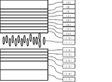
- Polarizing layer (2) Adhesive layer (3) Light transmissive substrate (4) Color filter layer (5) Planarizing layer (6) Retardation layer alignment film (7) Specific polymerizable liquid crystal composition Used retardation layer 1 (8) Retardation layer 2 using specific polymerizable liquid crystal composition (9) Transparent electrode layer (10) Alignment film (11) Specific liquid crystal composition (12) Alignment film (13) Pixel electrode layer (14) Light transmissive substrate (15) Adhesive layer (16) Polarizing layer (17 )Backlight
- FIG. 1 An example of the liquid crystal display device of the present invention is shown in FIG.
- a polarizing plate comprising a polarizing layer (1), an adhesive layer (2), and a light transmitting substrate (3) is provided with a color filter layer (4) and a planarizing layer (5). Furthermore, a first retardation layer (7), a second retardation layer (8) using a specific polymerizable composition between the alignment layer for retardation layer (6) and the transparent electrode layer (9). ).
- a specific liquid crystal composition (11) is sandwiched between the alignment film layers (10) and (12).
- a transparent electrode layer (9) and a color filter layer (4) serving as a common electrode are provided between one alignment film (10) and the substrate (3) of the two substrates having the alignment film (12) and the polarizing layer.
- a pixel electrode layer (13) is provided between the other alignment film (10) and the light-transmitting substrate (14).
- the glass substrate (14) on the backlight (17) side is also provided with an adhesive layer (15) and a polarizing layer (16).
- the two substrates in the display device are bonded together by a sealing material and a sealing material arranged in the peripheral region, and in many cases, a granular spacer or a photolithography method is used in order to maintain a distance between the substrates. Spacer columns made of the formed resin are arranged.
- FIG. 2 shows an example of a liquid crystal display device using only the retardation layer (7) without using the retardation layer (8).
- liquid crystal layer in the liquid crystal display device of the present invention has the general formula (I)
- R 1 and R 2 are each independently an alkyl group having 1 to 8 carbon atoms, an alkenyl group having 2 to 8 carbon atoms, an alkoxy group having 1 to 8 carbon atoms, or 2 to 2 carbon atoms
- 8 represents an alkenyloxy group
- A represents a 1,4-phenylene group or a trans-1,4-cyclohexylene group
- R 3 and R 4 are each independently an alkyl group having 1 to 8 carbon atoms, an alkenyl group having 2 to 8 carbon atoms, an alkoxy group having 1 to 8 carbon atoms, or 2 to 8 carbon atoms.
- Z 3 and Z 4 are each independently a single bond, —CH ⁇ CH—, —C ⁇ C—, —CH 2 CH 2 —, — (CH 2 ) 4 —, —COO—.
- the liquid crystal layer in the liquid crystal display device of the present invention contains 10 to 50% by weight of the compound represented by the general formula (I), preferably 15 to 48% by weight, and preferably 20 to 46% by weight. Is more preferable.
- R 1 and R 2 are each independently an alkyl group having 1 to 8 carbon atoms, an alkenyl group having 2 to 8 carbon atoms, an alkoxy group having 1 to 8 carbon atoms, or a carbon atom.
- R 1 represents an alkyl group having 3 carbon atoms
- R 2 is preferably an alkyl group having 2, 4 or 5 carbon atoms, or an alkenyl group having 2 to 3 carbon atoms
- R 2 is More preferred is an alkyl group having 2 carbon atoms.
- A represents a 1,4-phenylene group
- It preferably represents an alkyl group having 1 to 5 carbon atoms, an alkenyl group having 4 to 5 carbon atoms, an alkoxy group having 1 to 5 carbon atoms or an alkenyloxy group having 3 to 5 carbon atoms
- R 1 preferably represents an alkyl group, and in this case, an alkyl group having 1, 3 or 5 carbon atoms is particularly preferred.
- R 2 preferably represents an alkoxy group having 1 to 2 carbon atoms.
- the content of the compound represented by the general formula (I) in which at least one substituent of R 1 and R 2 is an alkyl group having 3 to 5 carbon atoms is in the compound represented by the general formula (I) It is preferably 50% by weight or more, more preferably 70% by weight or more, and further preferably 80% by weight or more.
- the content of the compound represented by the general formula (I) in which at least one substituent of R 1 and R 2 is an alkyl group having 3 carbon atoms is in the compound represented by the general formula (I) It is preferably 50% by weight or more, more preferably 70% by weight or more, still more preferably 80% by weight or more, and most preferably 100% by weight.
- the compound represented by the general formula (I) may be contained alone or in combination of two or more, but A represents a trans-1,4-cyclohexylene group, and A represents a 1,4-phenylene group. It is preferable to contain at least one compound. Further, the content of the compound represented by the general formula (I) in which A represents a trans-1,4-cyclohexylene group may be 50% by weight or more in the compound represented by the general formula (I). Preferably, 70% by weight or more is more preferable, and 80% by weight or more is further preferable.
- the compound represented by the general formula (I) is preferably a compound represented by the following general formula (Ia) to general formula (Ik).
- R 1 and R 2 each independently represents an alkyl group having 1 to 5 carbon atoms or an alkoxy group having 1 to 5 carbon atoms, and R 1 and R 2 in the general formula (I)) Similar embodiments are preferred.) In general formula (Ia) to general formula (Ik), general formula (Ia), general formula (Ib), general formula (Ic), and general formula (Ig) are preferable, and general formula (Ia), general formula (Ib) ) And general formula (Ic) are more preferable, and general formula (Ia) and general formula (Ib) are more preferable. Yes.
- the general formula (Ib) and the general formula (Ic) are preferable, and the general formula (Ib) and the general formula (Ic) are more preferably used in combination.
- the general formula (Ia) is preferable.
- the content of the compound represented by the general formula (Ia), the general formula (Ib) and the general formula (Ic) is 80% by weight or more in the compound represented by the general formula (I). It is preferably 90% by weight or more, more preferably 95% by weight or more, and most preferably 100% by weight.
- the content of the compound represented by the general formula (Ia) is 65% by weight to 100% by weight in the compound represented by the general formula (I), and the general formula (Ib) and the general formula (Ic)
- the content of the compound represented by general formula (I) is 0% to 35% by weight in the compound represented by general formula (I), or the content of the compound represented by general formula (Ia) is
- the content of the compound represented by the general formula (Ib) and the general formula (Ic) is 0% by weight to 10% by weight in the compound represented by the formula (I). It is preferably 90 to 100% by weight in the compound.
- the liquid crystal layer in the liquid crystal display device of the present invention contains 35 to 80% by weight of the compound represented by the general formula (II), preferably 40 to 75% by weight, and preferably 45 to 70% by weight. Is more preferable.
- R 3 represents an alkyl group having 1 to 8 carbon atoms, an alkenyl group having 2 to 8 carbon atoms, an alkoxy group having 1 to 8 carbon atoms, or an alkenyloxy group having 2 to 8 carbon atoms.
- it represents an alkyl group having 3 to 5 carbon atoms or an alkenyl group having 2 or 3 carbon atoms, and more preferably represents an alkyl group having 2 or 3 carbon atoms or an alkenyl group having 2 carbon atoms. It is particularly preferred to represent an alkyl group having 2 or 3 carbon atoms.
- R 4 represents an alkyl group having 1 to 8 carbon atoms, an alkenyl group having 4 to 8 carbon atoms, an alkoxy group having 1 to 8 carbon atoms, or an alkenyloxy group having 3 to 8 carbon atoms, It preferably represents an alkyl group having 1 to 5 carbon atoms or an alkoxy group having 1 to 5 carbon atoms, more preferably an alkyl group having 1 to 3 carbon atoms or an alkoxy group having 1 to 4 carbon atoms. More preferably, it represents an alkoxy group of 2-4.
- Z 3 and Z 4 are each independently a single bond, —CH ⁇ CH—, —C ⁇ C—, —CH 2 CH 2 —, — (CH 2 ) 4 —, —COO—, —OCO—, —OCH 2 —, —CH 2 O—, —OCF 2 — or —CF 2 O—, represents a single bond, —CH 2 CH 2 —, —COO—, —OCH 2 —, —CH 2 O—, —OCF It preferably represents 2 — or —CF 2 O—, and more preferably represents a single bond or —CH 2 O—.
- m and n each independently preferably represents an integer of 0 to 3, preferably an integer of 0 to 2, and m + n is preferably 1 to 3, and preferably 1 to 2.
- the liquid crystal layer in the liquid crystal display device of the present invention can contain 3 to 10 compounds represented by the general formula (II), preferably 4 to 9 compounds, and preferably 5 to 8 compounds. It is preferable to contain.
- the compound represented by the general formula (II) is preferably a compound represented by the following general formula (II-1) or (II-2).
- R 3 and R 4 are each independently an alkyl group having 1 to 8 carbon atoms, an alkenyl group having 2 to 8 carbon atoms, an alkoxy group having 1 to 8 carbon atoms, or an alkyl group having 2 to 8 carbon atoms.
- An alkenyloxy group, wherein Z 5 and Z 6 are each independently a single bond, —CH ⁇ CH—, —C ⁇ C—, —CH 2 CH 2 —, — (CH 2 ) 4 —, —COO—, —OCO—, —OCH 2 —, —CH 2 O—, —OCF 2 — or —CF 2 O— is represented, and m1, m2 and n2 each independently represents 0 or 1.
- R 3 preferably represents an alkyl group having 1 to 5 carbon atoms or an alkenyl group having 2 to 5 carbon atoms, and an alkyl group having 2 to 5 carbon atoms or the number of carbon atoms It is more preferably an alkenyl group having 2 to 4 carbon atoms, more preferably an alkyl group having 3 to 5 carbon atoms or an alkenyl group having 2 carbon atoms, and particularly preferably an alkyl group having 3 carbon atoms.
- R 4 preferably represents an alkyl group having 1 to 5 carbon atoms or an alkoxy group having 1 to 5 carbon atoms, and represents an alkyl group having 1 to 3 carbon atoms or an alkoxy group having 1 to 3 carbon atoms. More preferably, it represents an alkyl group having 3 carbon atoms or an alkoxy group having 2 carbon atoms, more preferably represents an alkoxy group having 2 carbon atoms, Z 5 represents a single bond,- It preferably represents CH 2 CH 2 —, —COO—, —OCH 2 —, —CH 2 O—, —OCF 2 — or —CF 2 O—, and more preferably represents a single bond or —CH 2 O—. preferable.
- the liquid crystal layer in the liquid crystal display device of the present invention preferably contains 15% to 60% by weight, and preferably contains 17% to 50% by weight of the compound represented by the general formula (II-1).
- the content is preferably from 40% by weight to 40% by weight, more preferably from 19% by weight to 30% by weight.
- the liquid crystal layer in the liquid crystal display device of the present invention can contain one or more compounds represented by the general formula (II-1), but preferably contains 1 to 6 types. It is preferable to contain 5 types, and it is preferable to contain 3 types or 4 types.
- R 3 preferably represents an alkyl group having 1 to 5 carbon atoms or an alkenyl group having 2 to 5 carbon atoms, and the alkyl group having 2 to 5 carbon atoms or the number of carbon atoms More preferably, it represents an alkenyl group having 2 to 4 carbon atoms, more preferably represents an alkyl group having 3 to 5 carbon atoms or an alkenyl group having 2 carbon atoms, and represents an alkyl group having 2 or 3 carbon atoms.
- R 4 represents an alkyl group having 1 to 5 carbon atoms or an alkoxy group having 1 to 5 carbon atoms, and an alkyl group having 1 to 3 carbon atoms or an alkoxy group having 1 to 3 carbon atoms. And more preferably an alkyl group having 3 carbon atoms or an alkoxy group having 2 carbon atoms, and Z 6 represents a single bond, —CH 2 CH 2 —, —COO—, —OCH 2 —. , -CH 2 O -, - OCF 2 - or preferably representing a -CF 2 O-, and more preferably represents a single bond or -CH 2 O-.
- the liquid crystal layer in the liquid crystal display device of the present invention preferably contains 10% by weight to 50% by weight of the compound represented by the general formula (II-2), preferably 15% by weight to 45% by weight, The content is preferably 20 to 40% by weight, more preferably 25 to 35% by weight.
- the liquid crystal layer in the liquid crystal display device of the present invention may contain one or more compounds represented by the general formula (II-2), but preferably contains 1 to 6 types. It is preferable to contain 5 types, and it is preferable to contain 3 types or 4 types.
- R 3 represents an alkyl group having 1 to 5 carbon atoms or an alkenyl group having 2 to 5 carbon atoms
- R 4a represents an alkyl group having 1 to 5 carbon atoms.
- R 3 is preferably the same embodiment as in general formula (II-1).
- R 4a is preferably an alkyl group having 1 to 3 carbon atoms, more preferably an alkyl group having 1 or 2 carbon atoms, and particularly preferably an alkyl group having 2 carbon atoms.
- R 3 is preferably the same embodiment as in general formula (II-1).
- R 4a is preferably an alkyl group having 1 to 3 carbon atoms, more preferably an alkyl group having 1 or 3 carbon atoms, and particularly preferably an alkyl group having 3 carbon atoms.
- general formulas (II-1a) to (II-1d) general formula (II-1a) and general formula (II-1c) are preferable for increasing the absolute value of dielectric anisotropy.
- general formula (II-1a) is preferred.
- the liquid crystal layer in the liquid crystal display device of the present invention preferably contains one or more compounds represented by the general formulas (II-1a) to (II-1d). It is preferable to contain 1 type or 2 types of compounds represented by general formula (II-1a).
- R 3 represents an alkyl group having 1 to 5 carbon atoms or an alkenyl group having 2 to 5 carbon atoms
- R 4b represents an alkyl group having 1 to 5 carbon atoms.
- R 3 is preferably the same embodiment as in general formula (II-1).
- R 4b is preferably an alkyl group having 1 to 3 carbon atoms, more preferably an alkyl group having 1 or 2 carbon atoms, and particularly preferably an alkyl group having 2 carbon atoms.
- R 3 is preferably the same embodiment as in general formula (II-1).
- R 4b is preferably an alkyl group having 1 to 3 carbon atoms, more preferably an alkyl group having 1 or 3 carbon atoms, and particularly preferably an alkyl group having 3 carbon atoms.
- general formulas (II-1e) to (II-1h) general formula (II-1e) and general formula (II-1g) are preferable in order to increase the absolute value of dielectric anisotropy. .
- R 3 represents an alkyl group having 1 to 5 carbon atoms or an alkenyl group having 2 to 5 carbon atoms
- R 4c represents an alkyl group having 1 to 5 carbon atoms.
- An embodiment similar to R 3 and R 4 in 2) is preferred.
- R 3 is preferably the same embodiment as in general formula (II-2).
- R 4c is preferably an alkyl group having 1 to 3 carbon atoms, more preferably an alkyl group having 1 or 2 carbon atoms, and particularly preferably an alkyl group having 2 carbon atoms.
- R 3 is preferably the same embodiment as in general formula (II-2).
- R 4c is preferably an alkyl group having 1 to 3 carbon atoms, more preferably an alkyl group having 1 or 3 carbon atoms, and particularly preferably an alkyl group having 3 carbon atoms.
- general formulas (II-2a) to (II-2d) general formula (II-2a) and general formula (II-2c) are preferable for increasing the absolute value of dielectric anisotropy.
- the general formula (II-2a) is preferable.
- R 3 represents an alkyl group having 1 to 5 carbon atoms or an alkenyl group having 2 to 5 carbon atoms
- R 4d represents an alkyl group having 1 to 5 carbon atoms.
- An embodiment similar to R 3 and R 4 in 2) is preferred.
- R 3 is preferably the same embodiment as in general formula (II-2).
- R 4d is preferably an alkyl group having 1 to 3 carbon atoms, more preferably an alkyl group having 1 or 2 carbon atoms, and particularly preferably an alkyl group having 2 carbon atoms.
- R 3 is preferably the same embodiment as in general formula (II-2).
- R 4d is preferably an alkyl group having 1 to 3 carbon atoms, more preferably an alkyl group having 1 or 3 carbon atoms, and particularly preferably an alkyl group having 2 carbon atoms.
- general formulas (II-2e) to (II-2i) general formula (II-2e) and general formula (II-2h) are preferable.
- the total content of the compounds represented by the general formula (I) and the general formula (II) is preferably 75% by weight to 100% by weight, and 80% by weight to 100%. % By weight is preferable, 85% by weight to 100% by weight is preferable, 90% by weight to 100% by weight is preferable, and 95% by weight to 100% by weight is preferable.
- the liquid crystal layer in the liquid crystal display device of the present invention further has the general formula (III)
- R 7 and R 8 are each independently an alkyl group having 1 to 8 carbon atoms, an alkenyl group having 2 to 8 carbon atoms, an alkoxy group having 1 to 8 carbon atoms, or 2 to 8 represents an alkenyloxy group
- D, E and F each independently represent a fluorine-substituted 1,4-phenylene group or trans-1,4-cyclohexylene
- Z 2 represents a single bond.
- the general formula (I), the general formula (II-1 ) And compounds represented by the general formula (II-2) are excluded.) It can also contain the compound represented by these.
- the compound represented by the general formula (III) is preferably contained in an amount of 1 to 20%, more preferably 2 to 15%, and more preferably 4 to 10%.
- R 7 is an alkyl group having 1 to 8 carbon atoms, an alkenyl group having 2 to 8 carbon atoms, an alkoxy group having 1 to 8 carbon atoms, or an alkenyloxy group having 2 to 8 carbon atoms.
- D represents trans-1,4-cyclohexylene
- it preferably represents an alkyl group having 1 to 5 carbon atoms or an alkenyl group having 2 to 5 carbon atoms, and an alkyl group or carbon having 2 to 5 carbon atoms More preferably, it represents an alkenyl group having 2 to 4 atoms, more preferably represents an alkyl group having 3 to 5 carbon atoms or an alkenyl group having 2 or 3 carbon atoms, and represents an alkyl group having 3 carbon atoms.
- D represents a 1,4-phenylene group optionally substituted with fluorine
- D preferably represents an alkyl group having 1 to 5 carbon atoms or an alkenyl group having 4 or 5 carbon atoms, More preferably, it represents a 5 alkyl group or an alkenyl group having 4 carbon atoms, and more preferably represents an alkyl group having 2 to 4 carbon atoms.
- R 8 represents an alkyl group having 1 to 8 carbon atoms, an alkenyl group having 2 to 8 carbon atoms, an alkoxy group having 1 to 8 carbon atoms, or an alkenyloxy group having 3 to 8 carbon atoms
- F represents trans-1,4-cyclohexylene
- it preferably represents an alkyl group having 1 to 5 carbon atoms or an alkenyl group having 2 to 5 carbon atoms, and an alkyl group or carbon having 2 to 5 carbon atoms
- it represents an alkenyl group having 2 to 4 atoms More preferably represents an alkyl group having 3 to 5 carbon atoms or an alkenyl group having 2 or 3 carbon atoms, and represents an alkyl group having 3 carbon atoms.
- F represents a 1,4-phenylene group optionally substituted with fluorine
- it preferably represents an alkyl group having 1 to 5 carbon atoms or an alkenyl group having 4 or 5 carbon atoms, More preferably, it represents a 5 alkyl group or an alkenyl group having 4 carbon atoms, and more preferably represents an alkyl group having 2 to 4 carbon atoms.
- R 7 and R 8 represent an alkenyl group and the bonded D or F represents a 1,4-phenylene group optionally substituted with fluorine
- the alkenyl group having 4 or 5 carbon atoms includes A structure is preferred.
- D, E, and F each independently represents a fluorine-substituted 1,4-phenylene group or trans-1,4-cyclohexylene, and represents a 2-fluoro-1,4-phenylene group, 2 , 3-difluoro-1,4-phenylene group, 1,4-phenylene group or trans-1,4-cyclohexylene, preferably 2-fluoro-1,4-phenylene group or 2,3-difluoro- 1,4-phenylene group and 1,4-phenylene group are more preferable, and 2,3-difluoro-1,4-phenylene group and 1,4-phenylene group are preferable.
- Z 2 is a single bond, -OCH 2 -, - OCO - , - CH 2 O- or represents a -COO-, single bond, it is preferable to represent a -CH 2 O-or -COO-, a single bond is more preferable.
- n represents 0, 1 or 2, but preferably represents 0 or 1. Also, if Z 2 represents a substituent other than a single bond, preferably it represents 1.
- the compound represented by the general formula (III) is represented by the general formula (III-1c) to the general formula (III-1e) from the viewpoint of increasing the negative dielectric anisotropy when n represents 1.
- the compounds represented by formulas (III-1f) to (III-1j) are preferred from the viewpoint of increasing the response speed.
- R 7 and R 8 each independently represents an alkyl group having 1 to 5 carbon atoms, an alkenyl group having 2 to 5 carbon atoms, or an alkoxy group having 1 to 5 carbon atoms, similar embodiments with R 7 and R 8 in (III) is preferred.
- the compound represented by the general formula (III) is represented by the general formula (III-2a) to the general formula (III-2h) from the viewpoint of increasing the negative dielectric anisotropy when n is 2. From the viewpoint of increasing the response speed, compounds represented by general formula (III-2j) to general formula (III-2l) are preferable.
- R 7 and R 8 each independently represents an alkyl group having 1 to 5 carbon atoms, an alkenyl group having 2 to 5 carbon atoms, or an alkoxy group having 1 to 5 carbon atoms, similar embodiments with R 7 and R 8 in (III) is preferred.
- the compound represented by the general formula (III) is preferably a compound represented by the general formula (III-3b) from the viewpoint of increasing the response speed when n is 0.
- R 7 and R 8 each independently represents an alkyl group having 1 to 5 carbon atoms, an alkenyl group having 2 to 5 carbon atoms, or an alkoxy group having 1 to 5 carbon atoms, similar embodiments with R 7 and R 8 in (III) is preferred.
- R 7 is preferably an alkyl group having 2 to 5 carbon atoms, more preferably an alkyl group having 3 carbon atoms.
- R 8 is preferably an alkoxy group having 1 to 3 carbon atoms, more preferably an alkoxy group having 2 carbon atoms.
- the liquid crystal layer in the liquid crystal display device of the present invention can use a nematic phase-isotropic liquid phase transition temperature (T ni ) in a wide range, but is preferably 60 to 120 ° C., 70 To 100 ° C is more preferable, and 70 to 85 ° C is particularly preferable.
- the dielectric anisotropy is preferably ⁇ 2.0 to ⁇ 6.0 at 25 ° C., more preferably ⁇ 2.5 to ⁇ 5.0, and ⁇ 2.5 to ⁇ 4. Particularly preferred is 0.
- the refractive index anisotropy is preferably 0.08 to 0.13 at 25 ° C., more preferably 0.09 to 0.12.
- the rotational viscosity ( ⁇ 1) is preferably 150 or less, more preferably 130 or less, and particularly preferably 120 or less.
- Z as a function of rotational viscosity and refractive index anisotropy shows a specific value.
- ⁇ 1 represents rotational viscosity and ⁇ n represents refractive index anisotropy.
- Z is preferably 13000 or less, more preferably 12000 or less, and particularly preferably 11000 or less.
- the liquid crystal layer in the liquid crystal display device of the present invention is required to have a specific resistance of 10 12 ( ⁇ ⁇ m) or more, preferably 10 13 ( ⁇ ⁇ m), when used for an active matrix display element. 10 14 ( ⁇ ⁇ m) or more is more preferable.
- the liquid crystal layer in the liquid crystal display device of the present invention may contain a normal nematic liquid crystal, a smectic liquid crystal, a cholesteric liquid crystal, an antioxidant, an ultraviolet absorber, a polymerizable monomer, etc., in addition to the above-described compound, depending on the application. good.
- X 1 and X 2 each independently represent a hydrogen atom or a methyl group
- Sp 1 and Sp 2 are each independently a single bond, an alkylene group having 1 to 8 carbon atoms, or —O— (CH 2 ) s — (wherein s represents an integer of 2 to 7, Represents an aromatic ring).
- Z 1 is —OCH 2 —, —CH 2 O—, —COO—, —OCO—, —CF 2 O—, —OCF 2 —, —CH 2 CH 2 —, —CF 2 CF 2 —, —CH ⁇ CH—COO—, —CH ⁇ CH—OCO—, —COO—CH ⁇ CH—, —OCO—CH ⁇ CH—, —COO—CH 2 CH 2 —, —OCO—CH 2 CH 2 —, —CH 2 CH 2 —COO—, —CH 2 CH 2 —OCO—, —COO—CH 2 —, —OCO—CH 2 —, —CH 2 —COO—, —CH 2 —OCO—, —CY 1 ⁇ CY 2 — (Wherein Y 1 and Y 2 each independently represents a fluorine atom or a hydrogen atom), —C ⁇ C— or a single bond; C represents a 1,4-phenylene group,
- X 1 and X 2 are both diacrylate derivatives represents a hydrogen atom, both preferably none of dimethacrylate derivatives having a methyl group, preferred compounds where one represents the other is a methyl group represents a hydrogen atom.
- diacrylate derivatives are the fastest, dimethacrylate derivatives are slow, asymmetric compounds are in the middle, and a preferred embodiment can be used depending on the application.
- a dimethacrylate derivative is particularly preferable.
- Sp 1 and Sp 2 each independently represent a single bond, an alkylene group having 1 to 8 carbon atoms or —O— (CH 2 ) s —, but at least one of them is a single bond in a PSA display element.
- a compound in which both represent a single bond or one in which one represents a single bond and the other represents an alkylene group having 1 to 8 carbon atoms or —O— (CH 2 ) s — is preferable.
- 1 to 4 alkyl groups are preferable, and s is preferably 1 to 4.
- Z 1 is —OCH 2 —, —CH 2 O—, —COO—, —OCO—, —CF 2 O—, —OCF 2 —, —CH 2 CH 2 —, —CF 2 CF 2 — or a single bond
- C represents a 1,4-phenylene group, a trans-1,4-cyclohexylene group or a single bond in which any hydrogen atom may be substituted with a fluorine atom, and a 1,4-phenylene group or a single bond is preferred.
- Z 1 is preferably a linking group other than a single bond.
- Z 1 is preferably a single bond.
- the ring structure between Sp 1 and Sp 2 is specifically preferably the structure described below.
- C represents a single bond and the ring structure is formed of two rings
- both ends shall be bonded to Sp 1 or Sp 2.
- the polymerizable compounds containing these skeletons are optimal for PSA-type liquid crystal display elements because of the alignment regulating power after polymerization, and a good alignment state can be obtained, so that display unevenness is suppressed or does not occur at all.
- general formula (V-1) to general formula (V-4) are particularly preferable, and general formula (V-2) is most preferable.
- Sp 2 represents an alkylene group having 2 to 5 carbon atoms.
- the polymerization proceeds even in the absence of a polymerization initiator, but a polymerization initiator may be contained in order to accelerate the polymerization.
- the polymerization initiator include benzoin ethers, benzophenones, acetophenones, benzyl ketals, acylphosphine oxides, and the like.
- a stabilizer may be added in order to improve storage stability.
- Examples of the stabilizer that can be used include hydroquinones, hydroquinone monoalkyl ethers, tert-butylcatechols, pyrogallols, thiophenols, nitro compounds, ⁇ -naphthylamines, ⁇ -naphthols, nitroso compounds, and the like. It is done.
- the liquid crystal layer in the present invention is useful for a liquid crystal display element, and includes AM-LCD (active matrix liquid crystal display element), TN (nematic liquid crystal display element), STN-LCD (super twisted nematic liquid crystal display element), OCB-LCD and Although it is useful for IPS-LCD (in-plane switching liquid crystal display element), it is particularly useful for AM-LCD and can be used for liquid crystal display elements for PSA mode, PSVA mode, VA mode, IPS mode or ECB mode.
- AM-LCD active matrix liquid crystal display element
- TN nematic liquid crystal display element
- STN-LCD super twisted nematic liquid crystal display element
- OCB-LCD OCB-LCD
- IPS-LCD in-plane switching liquid crystal display element
- the liquid crystal compound (polymerizable liquid crystal compound) having a polymerizable functional group of the present invention exhibits liquid crystallinity in a composition with another liquid crystal compound.
- the polymerizable liquid crystal compound alone may not exhibit liquid crystallinity.
- Handbook of Liquid Crystals D. Demus, JW Goodby, GW Gray, HW Spies, V. Vill, published by Wiley-VCH, 1998), Quarterly Chemical Review No.
- the polymerizable liquid crystal composition of the present invention contains one or more polymerizable liquid crystal compounds and a polymerization initiator, and further comprises a surfactant and other additives as necessary. In that case, it further contains a chiral compound.
- the retardation layer in the liquid crystal display device of the present invention uses an optical anisotropic body obtained by polymerizing a polymerizable liquid crystal composition containing 25% by weight or more of a liquid crystal compound having two or more polymerizable functional groups.
- the liquid crystal compound having two or more polymerizable functional groups is preferably a compound represented by the following general formula (1).
- P 1 represents a polymerizable functional group
- Sp 1 represents an alkylene group having 0 to 18 carbon atoms (the alkylene group is a carbon having one or more halogen atoms, a CN group, or a polymerizable functional group).
- M1 represents 0 or 1
- MG represents a mesogenic group or a mesogenic supporting group
- R 1 represents a hydrogen atom, a halogen atom, a cyano group or Represents an alkyl group having 1 to 18 carbon atoms
- M1 represents 0 or 1
- MG represents a mesogenic group or a mesogenic supporting group
- R 1 represents a hydrogen atom, a halogen atom, a cyano group or Represents an alkyl group having 1 to 18 carbon atoms
- M1 represents 0 or 1
- MG represents
- A1, A2, A3, A4 and A5 are each independently 1,4-phenylene group, 1,4-cyclohexylene group, 1,4-cyclohexenyl group, tetrahydropyran-2,5- Diyl group, 1,3-dioxane-2,5-diyl group, tetrahydrothiopyran-2,5-diyl group, 1,4-bicyclo (2,2,2) octylene group, decahydronaphthalene-2,6- Diyl group, pyridine-2,5-diyl group, pyrimidine-2,5-diyl group, pyrazine-2,5-diyl group, thiophene-2,5-diyl group-, 1,2,3,4-tetrahydronaphthalene -2,6-diyl group, 2,6-naphthylene group, phenanthrene-2,7-diyl group, 9,10-d
- P c represents a polymerizable functional group
- A represents —O—, —COO—, —OCO—, —OCH 2 —, —CH 2 O—, —CH 2 CH 2 OCO—, —COOCH 2 CH 2 —, —OCOCH 2 CH 2 —, or a single bond
- Sp 1c has the same meaning as Sp 1
- n1 represents 0 or 1
- mc represents 0 or 1.
- Z0, Z1, Z2, Z3, Z4 and Z5 are each independently —COO—, —OCO—, —CH 2 CH 2 —, —OCH 2 —, —CH 2 O—, —CH ⁇ CH—, —C ⁇ C—, —CH ⁇ CHCOO—, —OCOCH ⁇ CH—, —CH 2 CH 2 COO—, —CH 2 CH 2 OCO—, —COOCH 2 CH 2 —, —OCOCH 2 CH 2 —, —CONH -, -NHCO-, an alkyl group which may have a halogen atom having 2 to 10 carbon atoms or a single bond; n, l and k each independently represent 0 or 1, and 0 ⁇ n + 1 + k ⁇ 3. ). However, in the formula, there are two or more polymerizable functional groups.
- P 1 , P 1a and P c preferably represent a substituent selected from the polymerizable groups represented by the following formulas (P-1) to (P-20).
- the liquid crystal compound having two or more polymerizable functional groups can be used singly or in combination of two or more, but preferably 1 to 6 types, more preferably 2 to 5 types.
- the content of the liquid crystal compound having two or more polymerizable functional groups is preferably 25 to 100% by mass of the polymerizable liquid crystal composition, more preferably 30 to 100% by mass, and more preferably 35 to It is particularly preferable to contain 100% by mass.
- liquid crystal compound having two or more polymerizable functional groups a compound having two polymerizable functional groups is preferable, and a compound represented by the following general formula (2) is preferable.
- A1, A2, A3, A4, and A5 are each independently 1,4-phenylene group, 1,4-cyclohexylene group, 1,4-cyclohexenyl group, tetrahydropyran-2,5- Diyl group, 1,3-dioxane-2,5-diyl group, tetrahydrothiopyran-2,5-diyl group, 1,4-bicyclo (2,2,2) octylene group, decahydronaphthalene-2,6- Diyl group, pyridine-2,5-diyl group, pyrimidine-2,5-diyl group, pyrazine-2,5-diyl group, thiophene-2,5-diyl group-, 1,2,3,4-tetrahydronaphthalene -2,6-diyl group, 2,6-naphthylene group, phenanthrene-2,7-diyl group, 9,10-di
- Z0, Z1, Z2, Z3, Z4 and Z5 are each independently —COO—, —OCO—, —CH 2 CH 2 —, —OCH 2 —, —CH 2 O—, —CH ⁇ CH. —, —C ⁇ C—, —CH ⁇ CHCOO—, —OCOCH ⁇ CH—, —CH 2 CH 2 COO—, —CH 2 CH 2 OCO—, —COOCH 2 CH 2 —, —OCOCH 2 CH 2 —, —CONH—, —NHCO—, an alkyl group which may have a halogen atom having 2 to 10 carbon atoms or a single bond; n, l and k each independently represent 0 or 1, and 0 ⁇ n + 1 + k ⁇ 3.
- P 2a and P 2b represent a polymerizable functional group
- Sp 2a and Sp 2b each independently represent an alkylene group having 0 to 18 carbon atoms (the alkylene group is substituted with one or more halogen atoms or CN).
- each two or more CH 2 groups not one CH 2 group or adjacent present in this group to each other, in a manner that oxygen atoms are not directly bonded to each other, -O- , —S—, —NH—, —N (CH 3 ) —, —CO—, —COO—, —OCO—, —OCOO—, —SCO—, —COS— or —C ⁇ C—.
- m2 and n2 each independently represents 0 or 1.
- n, l and k each independently represent 0 or 1, and 0 ⁇ n + 1 + k ⁇ 3.
- P 2a and P 2b preferably represent a substituent selected from the polymerizable groups represented by the following formulas (P-1) to (P-20).
- the formula (P-1) or the formulas (P-2), (P-7), (P-12), (P-13) ) are preferred, and formulas (P-1), (P-7), and (P-12) are more preferred.
- examples of the general formula (2) can include the general formulas (2-1) to (2-4), but are not limited to the following general formula.
- P 2a , P 2b , Sp 2a , Sp 2b , A1, A2, A3, A4, A5, Z0, Z1, Z2, Z3, Z4, Z5, m2, and n2 are the same as defined in the general formula (2). Represents a thing.
- polymerizable liquid crystal compound having two polymerizable functional groups include compounds of formulas (2-5) to (2-29), but are not limited to the following compounds. .
- n each independently represents an integer of 1 to 18
- R represents a hydrogen atom, a halogen atom, an alkyl group having 1 to 6 carbon atoms, an alkoxy group having 1 to 6 carbon atoms, or a cyano group
- alkyl groups having 1 to 6 carbon atoms or alkoxy groups having 1 to 6 carbon atoms all of them may be unsubstituted or substituted by one or more halogen atoms.
- the liquid crystal compound having two polymerizable functional groups can be used singly or in combination of two or more, but preferably 1 to 5 types, more preferably 2 to 5 types.
- the content of the liquid crystal compound having two polymerizable functional groups is preferably 25 to 100% by mass, more preferably 30 to 100% by mass, and more preferably 35 to 100% by mass in the polymerizable composition. It is particularly preferable to contain it.
- liquid crystal compound having two or more polymerizable functional groups a compound having three polymerizable functional groups is also preferable.
- General formulas (3-1) to (3-18) can be mentioned, but are not limited to the following general formulas.
- A1, A2, A3, A4, and A5 represent the same definition as in the general formula (2).
- Z0, Z1, Z2, Z3, Z4, and Z5 represent the same definitions as in general formula (2).
- P 3a , P 3b , and P 3b each independently represent a polymerizable functional group
- Sp 3a , Sp 3b , and Sp 3c each independently represent an alkylene group having 0 to 18 carbon atoms (the alkylene group may be substituted by one or more halogen atoms or CN, 2 or more of CH 2 groups, independently of one another each of the present in the radical is not one CH 2 group or adjacent oxygen
- —O—, —S—, —NH—, —N (CH 3 ) —, —CO—, —COO—, —OCO—, —OCOO—, —SCO—, -COS- or -C ⁇ C- may be substituted.
- M3, n3 and k3 each independently represents 0 or 1.
- polymerizable liquid crystal compound having two polymerizable functional groups include compounds of formulas (3-19) to (3-26), but are not limited to the following compounds. .
- the liquid crystal compound having three polymerizable functional groups can be used singly or in combination of two or more, but preferably one to four, more preferably one to three.
- the content of the liquid crystal compound having three polymerizable functional groups is preferably 0 to 80% by mass, more preferably 0 to 70% by mass, and more preferably 0 to 60% by mass in the polymerizable liquid crystal composition. % Content is particularly preferable.
- the polymerizable liquid crystal composition in the present invention may further contain a liquid crystal compound having one polymerizable functional group.
- the liquid crystalline compound having one polymerizable functional group is preferably a compound represented by the following general formula (4).
- P 4 represents a polymerizable functional group
- Sp 4 represents an alkylene group having 0 to 18 carbon atoms (the alkylene group may be substituted by one or more halogen atoms or CN. independently one CH 2 group or adjacent to each other each of the two or more CH 2 groups not present in the form in which the oxygen atoms are not directly bonded to one another, -O -, - S -, - NH -, -N (CH 3 )-, -CO-, -COO-, -OCO-, -OCOO-, -SCO-, -COS- or -C ⁇ C- may be substituted), m4.
- MG represents a mesogenic group or a mesogenic support group
- R 4 represents a hydrogen atom, a halogen atom, a cyano group, or an alkyl group having 1 to 18 carbon atoms, and the alkyl group may be substituted with one or more halogen atoms or CN.
- One CH 2 group present or two or more non-adjacent CH 2 groups are each independently of each other in a form in which oxygen atoms are not directly bonded to each other, —O—, —S—, —NH—, It may be replaced by —N (CH 3 ) —, —CO—, —COO—, —OCO—, —OCOO—, —SCO—, —COS— or —C ⁇ C—.
- P 4 preferably represents a substituent selected from the polymerizable groups represented by the following formulas (P-1) to (P-20).
- the formula (P-1) or the formulas (P-2), (P-7), (P-12), (P-13) ) are preferred, and formulas (P-1), (P-7), and (P-12) are more preferred.
- Examples of the mesogenic group or mesogenic supporting group represented by MG include a group represented by the general formula (4-b).
- A1, A2, A3, A4 and A5 are each independently 1,4-phenylene group, 1,4-cyclohexylene group, 1,4-cyclohexenyl group, tetrahydropyran- 2,5-diyl group, 1,3-dioxane-2,5-diyl group, tetrahydrothiopyran-2,5-diyl group, 1,4-bicyclo (2,2,2) octylene group, decahydronaphthalene- 2,6-diyl group, pyridine-2,5-diyl group, pyrimidine-2,5-diyl group, pyrazine-2,5-diyl group, thiophene-2,5-diyl group-, 1,2,3 4-tetrahydronaphthalene-2,6-diyl group, 2,6-naphthylene group, phenanthrene-2,7-diyl group, 9,10
- Examples of general formula (4) include general formulas (4-1) to (4-4), but are not limited to the following general formula.
- A1, A2, A3, A4, and A5 represent the same definitions as in the general formula (4-b).
- Z0, Z1, Z2, Z3, Z4, and Z5 represent the same definitions as in the general formula (4-b).
- P 4a and P 4b each independently represent a polymerizable functional group
- Sp 4a and Sp 4b each independently represent an alkylene group having 0 to 18 carbon atoms
- the alkylene group represents one or more halogen atoms or may be substituted by CN, independently each two or more CH 2 groups not one CH 2 group or adjacent present in this group to each other, in a manner that oxygen atoms are not directly bonded to each other , —O—, —S—, —NH—, —N (CH 3 ) —, —CO—, —COO—, —OCO—, —OCOO—, —SCO—, —COS— or —C ⁇ C—.
- m4 and n4 each independently represents 0 or 1.
- Examples of the compound represented by the general formula (4) include compounds represented by the following formulas (4-5) to (4-31), but are not limited thereto.
- m and n each independently represent an integer of 1 to 18, and R, R 1 and R 2 each independently represents a hydrogen atom, an alkyl group having 1 to 6 carbon atoms, or an alkoxy having 1 to 6 carbon atoms.
- liquid crystal compounds having one polymerizable functional group can be used, but one to five types are preferable, and one to four types are more preferable.
- the content of the liquid crystal compound having one polymerizable functional group is preferably 0% by mass or more, more preferably 10% by mass or more, particularly preferably 20% by mass or more, and 75% by mass or less in the polymerizable liquid crystal composition. Is preferable, 70 mass% or less is more preferable, and 65 mass% or less is especially preferable.
- a chiral compound may be blended for the purpose of obtaining a chiral nematic phase.
- compounds having a polymerizable functional group in the molecule are particularly preferred.
- the chiral compound of the present invention may exhibit liquid crystallinity or non-liquid crystallinity.
- the chiral compound used in the present invention preferably has one or more polymerizable functional groups.
- examples of such compounds include JP-A-11-193287, JP-A-2001-158788, JP-T 2006-52669, JP-A-2007-269639, JP-A-2007-269640, 2009.
- -84178 which contains chiral saccharides such as isosorbide, isomannite, glucoside, etc., and a rigid group such as 1,4-phenylene group and 1,4-cyclohexylene group, and a vinyl group
- a polymerizable chiral compound having a polymerizable functional group such as an acryloyl group, a (meth) acryloyl group, or a maleimide group, a polymerizable chiral compound comprising a terpenoid derivative as described in JP-A-8-239666, NATURE VOL35, pages 467-469 (November 30, 1995) Issue), NATURE VOL392, pages 476-479 (issued on April 2, 1998), or the like, or a polymerizable chiral compound comprising a mesogenic group and a spacer having a chiral moiety, or JP-T-2004-504285.
- a polymerizable chiral compound containing a binaphthyl group as described in JP-A-2007-248945 is preferable for the polymerizable liquid crystal composition of the present invention.
- the compounding amount of the chiral compound needs to be appropriately adjusted depending on the helical induction force of the compound, but it is preferably 0 to 25% by mass, preferably 0 to 20% by mass in the polymerizable liquid crystal composition. Is more preferable, and the content of 0 to 15% by mass is particularly preferable.
- Examples of the general formula of the chiral compound include general formulas (5-1) to (5-4), but are not limited to the following general formula.
- Sp 5 represents an alkylene group having 0 to 18 carbon atoms, and the alkylene group is substituted with one or more halogen atoms, a CN group, or an alkyl group having 1 to 8 carbon atoms having a polymerizable functional group.
- A1, A2, A3, A4 and A5 are each independently 1,4-phenylene group, 1,4-cyclohexylene group, 1,4-cyclohexenyl group, tetrahydropyran-2,5-diyl group, , 3-dioxane-2,5-diyl group, tetrahydrothiopyran-2,5-diyl group, 1,4-bicyclo (2,2,2) octylene group, decahydronaphthalene-2,6-diyl group, pyridine -2,5-diyl group, pyrimidine-2,5-diyl group, pyrazine-2,5-diyl group, thiophene-2,5-diyl group-, 1,2,3,4-tetrahydronaphthalene-2,6 -Diyl group, 2,6-naphthylene group, phenanthrene-2,7-diyl group, 9,10-
- R 5a and R 5b are represented by the general formula (5-a)
- P 5a represents a polymerizable functional group, and Sp 5a represents the same meaning as Sp 1 ).
- P 5a preferably represents a substituent selected from the polymerizable groups represented by the following formulas (P-1) to (P-20).
- the formula (P-1) or the formulas (P-2), (P-7), (P-12), (P-13) ) are preferred, and formulas (P-1), (P-7), and (P-12) are more preferred.
- chiral compound examples include compounds (5-5) to (5-25), but are not limited to the following compounds.
- m, n, k, and l each independently represent an integer of 1 to 18, R 1 to R 4 each independently represent a hydrogen atom, an alkyl group having 1 to 6 carbon atoms, or 1 to 6 carbon atoms. An alkoxy group, a carboxyl group, and a cyano group. When these groups are alkyl groups having 1 to 6 carbon atoms or alkoxy groups having 1 to 6 carbon atoms, all of them may be unsubstituted or substituted by one or more halogen atoms. .
- Organic solvent may be added to the polymerizable liquid crystal composition in the present invention and used as a polymerizable liquid crystal composition solution.
- organic solvent in which a polymeric liquid crystal compound shows favorable solubility is preferable, and it is preferable that it is an organic solvent which can be dried at the temperature of 100 degrees C or less.
- solvents examples include aromatic hydrocarbons such as toluene, xylene, cumene, and mesitylene, ester solvents such as methyl acetate, ethyl acetate, propyl acetate, and butyl acetate, methyl ethyl ketone, methyl isobutyl ketone, cyclohexanone, cyclohexane, and the like.
- Ketone solvents such as pentanone, ether solvents such as tetrahydrofuran, 1,2-dimethoxyethane and anisole, amide solvents such as N, N-dimethylformamide and N-methyl-2-pyrrolidone, propylene glycol monomethyl ether acetate , Diethylene glycol monomethyl ether acetate, ⁇ -butyrolactone, chlorobenzene and the like.
- amide solvents such as N, N-dimethylformamide and N-methyl-2-pyrrolidone
- propylene glycol monomethyl ether acetate Diethylene glycol monomethyl ether acetate, ⁇ -butyrolactone, chlorobenzene and the like.
- amide solvents such as N, N-dimethylformamide and N-methyl-2-pyrrolidone
- propylene glycol monomethyl ether acetate Diethylene glycol monomethyl ether acetate, ⁇ -butyrolactone, chlorobenzene and the like.
- the ratio of the organic solvent to be used is not particularly limited as long as the polymerizable liquid crystal composition used in the present invention is usually applied by coating, as long as the applied state is not significantly impaired, but is contained in the polymerizable liquid crystal composition solution.
- the total amount of organic solvents to be used is preferably 1 to 60% by mass, more preferably 3 to 55% by mass, and particularly preferably 5 to 50% by mass.
- the polymerizable liquid crystal compound is dissolved in the organic solvent, it is preferably heated and stirred in order to uniformly dissolve the polymerizable liquid crystal compound.
- the heating temperature at the time of heating and stirring may be appropriately adjusted in consideration of the solubility of the polymerizable liquid crystal compound to be used in the organic solvent, but is preferably 15 ° C to 110 ° C, more preferably 15 ° C to 105 ° C from the viewpoint of productivity.
- 15 ° C to 100 ° C is more preferable, and 20 ° C to 90 ° C is particularly preferable.
- the stirring rotation speed when preparing the polymerizable liquid crystal composition solution is preferably adjusted as appropriate depending on the stirring device used. However, in order to obtain a uniform polymerizable liquid crystal composition solution, the stirring rotation speed is set to 10 rpm to 1000 rpm. Is preferable, 50 rpm to 800 rpm is more preferable, and 150 rpm to 600 rpm is particularly preferable.
- Polymerization inhibitor In order to improve the solution stability of the polymerizable liquid crystal composition in the present invention, it is preferable to add a polymerization inhibitor.
- the polymerization inhibitor include phenol compounds, quinone compounds, amine compounds, thioether compounds, nitroso compounds, and the like.
- phenolic compounds include p-methoxyphenol, cresol, t-butylcatechol, 3.5-di-t-butyl-4-hydroxytoluene, 2.2'-methylenebis (4-methyl-6-t-butylphenol) 2.2′-methylenebis (4-ethyl-6-tert-butylphenol), 4.4′-thiobis (3-methyl-6-tert-butylphenol), 4-methoxy-1-naphthol, 4,4′- Dialkoxy-2,2′-bi-1-naphthol, and the like.
- quinone compounds include hydroquinone, methylhydroquinone, tert-butylhydroquinone, p-benzoquinone, methyl-p-benzoquinone, tert-butyl-p-benzoquinone, 2,5-diphenylbenzoquinone, 2-hydroxy-1,4-naphthoquinone 1,4-naphthoquinone, 2,3-dichloro-1,4-naphthoquinone, anthraquinone, diphenoquinone and the like.
- amine compounds include p-phenylenediamine, 4-aminodiphenylamine, N.I. N'-diphenyl-p-phenylenediamine, Ni-propyl-N'-phenyl-p-phenylenediamine, N- (1.3-dimethylbutyl) -N'-phenyl-p-phenylenediamine, N.I. N′-di-2-naphthyl-p-phenylenediamine, diphenylamine, N-phenyl- ⁇ -naphthylamine, 4.4′-dicumyl-diphenylamine, 4.4′-dioctyl-diphenylamine and the like.
- thioether compounds include phenothiazine and distearyl thiodipropionate.
- nitroso compounds include N-nitrosodiphenylamine, N-nitrosophenylnaphthylamine, N-nitrosodinaphthylamine, p-nitrosophenol, nitrosobenzene, p-nitrosodiphenylamine, ⁇ -nitroso- ⁇ -naphthol, N, N-dimethyl p-nitrosoaniline, p-nitrosodiphenylamine, p-nitronedimethylamine, p-nitrone-N, N-diethylamine, N-nitrosoethanolamine, N-nitrosodi-n-butylamine, N-nitroso-N-n-butyl- 4-butanolamine, N-nitroso-diisopropanolamine, N-nitroso-N-ethyl-4-butanolamine, 5-nitroso-8-hydroxyquinoline, N-nitrosomorpholine, N-nitroso N-
- the addition amount of the polymerization inhibitor is preferably 0.01 to 1.0% by mass and more preferably 0.05 to 0.5% by mass with respect to the polymerizable liquid crystal composition.
- antioxidant In order to improve the solution stability of the polymerizable liquid crystal composition in the present invention, it is preferable to add an antioxidant or the like.
- antioxidants include hydroquinone derivatives, nitrosamine polymerization inhibitors, hindered phenol antioxidants, and more specifically, tert-butyl hydroquinone, methyl hydroquinone, Wako Pure Chemical Industries, Ltd.
- the addition amount of the antioxidant is preferably 0.01 to 2.0% by mass and more preferably 0.05 to 1.0% by mass with respect to the polymerizable liquid crystal composition.
- the polymerizable liquid crystal composition in the present invention preferably contains a photopolymerization initiator. It is preferable to contain at least one photopolymerization initiator.
- a photopolymerization initiator e.g., “Irgacure 651”, “Irgacure 184”, “Darocur 1173”, “Irgacure 907”, “Irgacure 127”, “Irgacure 369”, “Irgacure 379”, “Irgacure 819”, “ “Irgacure 2959”, “Irgacure 1800", “Irgacure 250", “Irgacure 754", “Irgacure 784", "Irgacure OXE01”, “Irgacure OXE02”, “Lucirin TPO”, "Darocure 1173", “Darocure MBF” and LAMBSON “Esacure 1001M”, “Esacur
- the amount of the photopolymerization initiator used is preferably from 0.1 to 10% by weight, particularly preferably from 0.5 to 5% by weight, based on the polymerizable liquid crystal composition. These can be used alone or in combination of two or more, and a sensitizer or the like may be added.
- thermal polymerization initiator As the thermal polymerization initiator used in the thermal polymerization, known ones can be used. For example, methyl acetoacetate peroxide, cumene hydroperoxide, benzoyl peroxide, bis (4-t-butylcyclohexyl) peroxide.
- Organic peroxides such as dicumyl peroxide, isobutyl peroxide, di (3-methyl-3-methoxybutyl) peroxydicarbonate, 1,1-bis (t-butylperoxy) cyclohexane, 2,2 ′ -Azobisisobutyronitrile, 2,2 Azonitrile compounds such as' -azobis (2,4-dimethylvaleronitrile), azoamidin compounds such as 2,2'-azobis (2-methyl-N-phenylpropion-amidin) dihydrochloride, 2,2'azobis ⁇ 2 Azoamide compounds such as -methyl-N- [1,1-bis (
- the polymerizable liquid crystal composition in the present invention may contain at least one surfactant in order to reduce film thickness unevenness when an optical anisotropic body is used.
- Surfactants that can be included include alkyl carboxylates, alkyl phosphates, alkyl sulfonates, fluoroalkyl carboxylates, fluoroalkyl phosphates, fluoroalkyl sulfonates, polyoxyethylene derivatives, fluoro Examples thereof include alkylethylene oxide derivatives, polyethylene glycol derivatives, alkylammonium salts, fluoroalkylammonium salts and the like, and fluorine-containing surfactants are particularly preferable.
- the addition amount of the surfactant is preferably 0.01 to 2% by mass and more preferably 0.05 to 0.5% by mass with respect to the polymerizable liquid crystal composition. Further, by using the above surfactant, when the polymerizable liquid crystal composition of the present invention is an optically anisotropic material, there are some which can effectively reduce the tilt angle of the air interface.
- the polymerizable liquid crystal composition according to the present invention has the effect of effectively reducing the tilt angle of the air interface when it is an optical anisotropic body, and is represented by the following general formula (6), except for the surfactant. Examples thereof include compounds having a unit having a weight average molecular weight of 100 or more.
- R 11, R 12, R 13 and R 14 are each independently a hydrogen atom, a hydrocarbon group of a halogen atom or a carbon atom number of 1-20, hydrogen atoms in the hydrocarbon group may include one or more It may be substituted with a halogen atom.
- suitable compounds represented by the general formula (6) include polyethylene, polypropylene, polyisobutylene, paraffin, liquid paraffin, chlorinated polypropylene, chlorinated paraffin, and chlorinated liquid paraffin.
- the compound represented by the general formula (6) is preferably added in the step of preparing a polymerizable solution by mixing a polymerizable compound in an organic solvent and heating and stirring, but then the photopolymerization is started in the polymerizable solution.
- the addition amount of the compound represented by the general formula (6) is preferably 0.01 to 1% by mass, and preferably 0.05 to 0.5% by mass with respect to the polymerizable liquid crystal composition solution. More preferred.
- a chain transfer agent in order to further improve the adhesion to the substrate when it is an optically anisotropic body.
- the chain transfer agent is preferably a thiol compound, more preferably a monothiol, dithiol, trithiol, or tetrathiol compound, and even more preferably a trithiol compound.
- compounds represented by the following general formulas (6-1) to (6-12) are preferable.
- R 65 represents an alkyl group having 2 to 18 carbon atoms, and the alkyl group may be linear or branched, and one or more methylene groups in the alkyl group are oxygen atoms.
- a sulfur atom that is not directly bonded to each other may be substituted with an oxygen atom, a sulfur atom, —CO—, —OCO—, —COO—, or —CH ⁇ CH—
- R 66 is a carbon atom Represents an alkylene group of 2 to 18, and one or more methylene groups in the alkylene group are oxygen atoms, sulfur atoms, —CO—, —OCO—, wherein oxygen atoms and sulfur atoms are not directly bonded to each other.
- —COO—, or —CH ⁇ CH— may be substituted.
- the chain transfer agent is preferably added in the step of mixing the polymerizable liquid crystal compound in an organic solvent and heating and stirring to prepare a polymerizable solution, but is added in the subsequent step of mixing the polymerization initiator in the polymerizable solution. It may be added in both steps.
- the addition amount of the chain transfer agent is preferably 0.5 to 10% by mass and more preferably 1.0 to 5.0% by mass with respect to the polymerizable liquid crystal composition.
- a non-polymerizable liquid crystal compound or a non-liquid crystalline polymerizable compound is preferably added in the step of preparing a polymerizable solution by mixing the polymerizable compound with an organic solvent and stirring under heating. You may add in the process of mixing a polymerization initiator with a solution, and may add in both processes. The amount of these compounds added is preferably 20% by mass or less, more preferably 10% by mass or less, and still more preferably 5% by mass or less with respect to the polymerizable liquid crystal composition.
- additives such as a thixotropic agent, an ultraviolet absorber, an infrared absorber, an antioxidant, a surface treatment agent, and the like may be added according to the purpose. It can be added to such an extent that the orientation ability is not significantly reduced.
- the polymerizable liquid crystal composition in the present invention is applied onto a substrate having an alignment function, and the liquid crystal molecules in the polymerizable liquid crystal composition of the present invention are uniformly aligned while maintaining a smectic phase and a nematic phase, By polymerizing, the optical anisotropic body of the present invention is obtained.
- orientation modes of positive A plate, negative A plate, positive C plate, negative C plate, biaxial plate, positive O plate, and negative O plate can be applied.
- the positive A plate means an optical anisotropic body in which the polymerizable liquid crystal composition is homogeneously aligned.
- a negative C plate means the optically anisotropic body which made the polymerizable liquid crystal composition the cholesteric orientation.
- a positive A plate as the first retardation layer in order to widen the viewing angle by compensating the viewing angle dependence of the polarization axis orthogonality.
- the positive A plate has a refractive index in the in-plane slow axis direction of the film as nx, a refractive index in the in-plane fast axis direction of the film as ny, and a refractive index in the thickness direction of the film as nz
- the positive A plate preferably has an in-plane retardation value in the range of 30 to 500 nm at a wavelength of 550 nm.
- the thickness direction retardation value is not particularly limited.
- the Nz coefficient is preferably in the range of 0.9 to 1.1.
- a so-called negative C plate having negative refractive index anisotropy is preferably used as the second retardation layer. Further, a negative C plate may be laminated on a positive A plate.
- the negative C plate has a refractive index nx in the in-plane slow axis direction of the retardation layer, ny in the in-plane fast axis direction of the retardation layer, and a refractive index in the thickness direction of the retardation layer.
- the thickness direction retardation value of the negative C plate is preferably in the range of 20 to 400 nm.
- the refractive index anisotropy in the thickness direction is represented by a thickness direction retardation value Rth defined by the equation (2).
- the thickness direction retardation value Rth is an in-plane retardation value R 0 , and is 50 with the slow axis as the tilt axis.
- the film thickness d Using the retardation value R 50 measured at an incline, the film thickness d, and the average refractive index n 0 of the film, nx, ny, nz can be obtained and calculated by substituting these into equation (2).
- the Nz coefficient can be calculated from the equation (3). The same applies to other descriptions in the present specification.
- R 0 (nx ⁇ ny) ⁇ d (1)
- Rth [(nx + ny) / 2 ⁇ nz] ⁇ d (2)
- Nz coefficient (nx ⁇ nz) / (nx ⁇ ny) (3)
- R 50 (nx ⁇ ny ′) ⁇ d / cos ( ⁇ ) (4)
- ny ′ ny ⁇ nz / [ny 2 ⁇ sin 2 ( ⁇ ) + nz 2 ⁇ cos 2 ( ⁇ )] 1/2 (7)
- phase difference measuring device In the commercially available phase difference measuring device, the numerical calculation shown here is automatically performed in the device, and the in-plane retardation value R0 , the thickness direction retardation value Rth, etc. are automatically displayed. There are many.
- An example of such a measuring apparatus is RETS-100 (manufactured by Otsuka Chemical Co., Ltd.).
- the substrate used for the optical anisotropic body in the present invention is a substrate that is usually used for liquid crystal devices, displays, optical components and optical films, and is heated during drying after the application of the polymerizable composition solution of the present invention. If it is the material which has heat resistance which can endure, there will be no restriction
- a substrate include organic materials such as a glass substrate, a metal substrate, a ceramic substrate, and a plastic substrate.
- the substrate when the substrate is an organic material, examples thereof include cellulose derivatives, polyolefins, polyesters, polyolefins, polycarbonates, polyacrylates, polyarylates, polyether sulfones, polyimides, polyphenylene sulfides, polyphenylene ethers, nylons, and polystyrenes.
- plastic substrates such as polyester, polystyrene, polyolefin, cellulose derivatives, polyarylate, and polycarbonate are preferable.
- a shape of a base material you may have a curved surface other than a flat plate. These base materials may have an electrode layer, an antireflection function, and a reflection function as needed.
- these substrates may be subjected to surface treatment.
- the surface treatment include ozone treatment, plasma treatment, corona treatment, silane coupling treatment, and the like.
- an applicator method As an application method for obtaining an optical anisotropic body in the present invention, an applicator method, a bar coating method, a spin coating method, a roll coating method, a direct gravure coating method, a reverse gravure coating method, a flexo coating method, an ink jet method, and a die coating A publicly known method such as a method, a cap coating method, a dip coating method, or a slit coating method can be used.
- the polymerizable liquid crystal composition is applied and then dried.
- the liquid crystal compound in the polymerizable liquid crystal composition is generally in a state in which it is horizontally aligned, vertically aligned, hybrid aligned, or cholesteric aligned (planar aligned) with respect to the substrate. It is performed by irradiation with light such as ultraviolet rays or by heating.
- irradiation with ultraviolet light specifically, irradiation with ultraviolet light of 390 nm or less is preferable, and irradiation with light having a wavelength of 250 to 370 nm is most preferable.
- the polymerizable composition causes decomposition or the like due to ultraviolet light of 390 nm or less
- This light is preferably diffused light and unpolarized light.
- Examples of the method for polymerizing the polymerizable liquid crystal composition in the present invention include a method of irradiating active energy rays and a thermal polymerization method, but a method of irradiating active energy rays is preferred because the reaction proceeds at room temperature. Among them, a method of irradiating light such as ultraviolet rays is preferable because the operation is simple.
- the temperature at the time of irradiation is preferably set to 50 ° C. or less as much as possible in order to avoid the induction of thermal polymerization of the polymerizable liquid crystal composition at a temperature at which the polymerizable liquid crystal composition of the present invention can maintain the liquid crystal phase.
- the liquid crystal composition usually has a liquid crystal phase within a range from the C (solid phase) -N (nematic) transition temperature (hereinafter abbreviated as the CN transition temperature) to the NI transition temperature in the temperature rising process. Indicates.
- the CN transition temperature N (nematic) transition temperature
- the temperature lowering process since the thermodynamically non-equilibrium state is obtained, there is a case where the liquid crystal state is not solidified even at a temperature below the CN transition temperature. This state is called a supercooled state.
- the liquid crystal composition in a supercooled state is also included in the state in which the liquid crystal phase is retained.
- irradiation with ultraviolet light of 390 nm or less is preferable, and irradiation with light having a wavelength of 250 to 370 nm is most preferable.
- the polymerizable composition causes decomposition or the like due to ultraviolet light of 390 nm or less
- This light is preferably diffused light and unpolarized light.
- Ultraviolet irradiation intensity in the range of 0.05kW / m 2 ⁇ 10kW / m 2 is preferred.
- the range of 0.2 kW / m 2 to 2 kW / m 2 is preferable.
- the alignment was regulated in advance by applying an electric field, magnetic field or temperature to the unpolymerized polymerizable liquid crystal composition, and the state was maintained.
- An optical anisotropic body having a plurality of regions having different orientation directions can also be obtained by irradiating light from above the mask and polymerizing it.
- the optical anisotropic body obtained by polymerizing the polymerizable liquid crystal composition in the present invention can be peeled off from the substrate and used alone as an optical anisotropic body, or can be used as an optical anisotropic body as it is without peeling from the substrate. You can also In particular, since it is difficult to contaminate other members, it is useful when used as a laminated substrate or by being attached to another substrate.
- the base material may be provided with an alignment film so that the polymerizable composition is oriented when the polymerizable composition solution of the present invention is applied and dried.
- the alignment treatment include stretching treatment, rubbing treatment, polarized ultraviolet visible light irradiation treatment, ion beam treatment, oblique deposition treatment of SiO 2 on the substrate, and the like.
- Such alignment films include polyimide, polysiloxane, polyamide, polyvinyl alcohol, polycarbonate, polystyrene, polyphenylene ether, polyarylate, polyethylene terephthalate, polyethersulfone, epoxy resin, epoxy acrylate resin, acrylic resin, coumarin compound, chalcone.
- the compound include compounds, cinnamate compounds, fulgide compounds, anthraquinone compounds, azo compounds, and arylethene compounds.
- the compound subjected to the alignment treatment by rubbing is preferably an alignment treatment or a compound in which crystallization of the material is promoted by inserting a heating step after the alignment treatment.
- the liquid crystal display device of the present invention may have a color filter.
- the color filter includes a black matrix and at least an RGB three-color pixel portion. Any method may be used for forming the color filter layer.
- a color filter layer is formed by applying a color coloring composition containing a pigment carrier and a color pigment dispersed therein to form a predetermined pattern, and curing this to obtain a colored pixel, and a color filter layer. Can be formed.
- a color coloring composition containing a pigment carrier and a color pigment dispersed therein to form a predetermined pattern, and curing this to obtain a colored pixel, and a color filter layer.
- the pigment contained in the color coloring composition an organic pigment and / or an inorganic pigment can be used.
- the color coloring composition may contain one kind of organic or inorganic pigment, and may contain a plurality of kinds of organic pigments and / or inorganic pigments.
- the pigment preferably has high color developability and high heat resistance, particularly high heat decomposition resistance
- organic pigments for red coloring compositions include C.I. I. Pigment Red 7, 14, 41, 48: 2, 48: 3, 48: 4, 81: 1, 81: 2, 81: 3, 81: 4, 146, 168, 177, 178, 179, 184, 185, Red pigments such as 187, 200, 202, 208, 210, 246, 254, 255, 264, 270, 272 and 279 can be used.
- the organic pigment of the red coloring composition a mixture of a red pigment and a yellow pigment may be used.
- Examples of the organic pigment of the green coloring composition include C.I. I. Green pigments such as Pigment Green 7, 10, 36, and 37 can be used.
- As the organic pigment of the green coloring composition a mixture of a green pigment and a yellow pigment may be used. As this yellow pigment, the thing similar to having illustrated about the red coloring composition can be used, for example.
- Examples of the organic pigment of the blue coloring composition include C.I. I. Blue pigments such as Pigment Blue 15, 15: 1, 15: 2, 15: 3, 15: 4, 15: 6, 16, 22, 60, and 64 can be used.
- As an organic pigment of the blue coloring composition a mixture of a blue pigment and a purple pigment may be used.
- Examples of the purple pigment include C.I. I. Pigment Violet 1, 19, 23, 27, 29, 30, 32, 37, 40, 42, or 50 can be used.
- inorganic pigments include, for example, yellow lead, zinc yellow, red bean (red iron oxide (III)), cadmium red, ultramarine blue, bitumen, chromium oxide green, and cobalt green metal oxide powder, metal sulfide powder, or Metal powder etc. can be used.
- Inorganic pigments can be used in combination with organic pigments, for example, in order to achieve good coatability, sensitivity, developability, and the like while balancing chroma and lightness.
- the color coloring composition may further contain a coloring component other than the pigment.
- the coloring composition may contain a dye as long as sufficient heat resistance can be achieved. In this case, toning using a dye is possible.
- the pigment carrier contained in the above-mentioned color coloring composition is composed of a resin, a precursor thereof, or a mixture thereof.
- the resin include thermoplastic resins, thermosetting resins, and photosensitive resins, and precursors thereof include polyfunctional monomers or oligomers that are cured by irradiation with radiation to form a resin. These can be used alone or in admixture of two or more.
- a photopolymerization initiator may be added to the color coloring composition, and a sensitizer may be added in some cases.
- the color coloring composition may further contain a chain transfer agent such as a polyfunctional thiol.
- the color coloring composition is, for example, a dispersion of three or more types of pigments such as a three roll mill, a two roll mill, a sand mill, a kneader and an attritor in a pigment carrier and an organic solvent together with the photopolymerization initiator as necessary. It can be manufactured by finely dispersing using an apparatus.
- the coloring composition containing two or more kinds of pigments may be produced by preparing a dispersion containing different pigments and mixing the dispersions.
- a dispersion aid such as a resin-type pigment dispersant, a surfactant, and a pigment derivative can be used.
- the dispersion aid improves the dispersibility of the pigment and suppresses reaggregation of the pigment after dispersion. Therefore, when a coloring composition obtained by dispersing a pigment in a pigment carrier and an organic solvent using a dispersion aid is used, a color filter having excellent transparency can be obtained.
- the dispersion aid is, for example, 0.1 to 40 in 100 parts by weight of the pigment in the coloring composition. Parts by weight are preferred, more preferably 0.1 to 30 parts by weight.
- the resin-type pigment dispersant includes a pigment affinity part having a property of adsorbing to the pigment and a part compatible with the pigment carrier.
- the resin type pigment dispersant is adsorbed on the pigment and stabilizes the dispersibility of the pigment on the pigment carrier.
- examples of the resin-type pigment dispersant include polycarboxylic acid esters such as polyurethane and polyacrylate, unsaturated polyamide, polycarboxylic acid, polycarboxylic acid amine salt, polycarboxylic acid partial amine salt, polycarboxylic acid ammonium salt, and polycarboxylic acid.
- the liquid crystal display device of the present invention may have an alignment film for aligning the liquid crystal composition on the surface of the first substrate that contacts the liquid crystal composition on the second substrate.
- the alignment film material transparent organic materials such as polyimide, polyamide, BCB (Penzocyclobutene Polymer), polyvinyl alcohol and the like can be used.
- p-phenylenediamine, 4,4′-diaminodiphenylmethane Aliphatic or alicyclic tetracarboxylic anhydrides such as aliphatic or alicyclic diamines, butanetetracarboxylic anhydride, 2,3,5-tricarboxycyclopentylacetic anhydride, pyromellitic dianhydride
- a polyimide alignment film obtained by imidizing a polyamic acid synthesized from an aromatic tetracarboxylic anhydride such as a product is preferable.
- rubbing is generally used as a method for imparting orientation, but when used for a vertical orientation film or the like, it can be used without imparting orientation.
- a photo-alignment material containing chalcone, cinnamate, cinnamoyl or azo group in the compound can be used, and it may be used in combination with materials such as polyimide and polyamide. May use rubbing or photo-alignment technology.
- photo-alignment materials include polyimide having a cyclic cycloalkane, wholly aromatic polyarylate, polyvinyl cinnamate as disclosed in JP-A-5-232473, polyvinyl ester of paramethoxycinnamic acid, JP-A-6-287453.
- Examples thereof include cinnamate derivatives as disclosed in JP-A-6-289374, maleimide derivatives as disclosed in JP-A-2002-265541, and the like. Specifically, compounds represented by the following formulas (7-1) to (7-11) are preferable.
- R 5 represents a hydrogen atom, a halogen atom, an alkyl group having 1 to 3 carbon atoms, an alkoxy group or a nitro group
- R 6 represents a hydrogen atom or an alkyl group having 1 to 10 carbon atoms.
- the group may be linear or branched, and any hydrogen atom in the alkyl group may be substituted with a fluorine atom, and one —CH 2 — or adjacent group in the alkyl group may be substituted.
- Two or more —CH 2 — that are not present are each independently —O—, —S—, —CO—, —COO—, —OCO—, —CO—S—, —S—CO—, —O.
- n 4 to 100,000
- m represents an integer of 1 to 10.
- R 7 represents a hydrogen atom, a halogen atom, a halogenated alkyl group, an allyloxy group, a cyano group, a nitro group, an alkyl group, a hydroxyalkyl group, an alkoxy group, a carboxy group or an alkali metal salt thereof, an alkoxycarbonyl group, a halogenated methoxy group.
- Hydroxy group, sulfonyloxy group or alkali metal salt thereof, amino group, carbamoyl group, sulfamoyl group or (meth) acryloyl group, (meth) acryloyloxy group, (meth) acryloylamino group, vinyl group, vinyloxy group and maleimide group Represents a polymerizable functional group selected from the group consisting of
- the alignment film is generally formed by applying the alignment film material on a substrate by a method such as spin coating to form a resin film, but a uniaxial stretching method, Langmuir-Blodgett method, or the like can also be used. .
- a conductive metal oxide can be used as a material for the transparent electrode.
- the metal oxide include indium oxide (In 2 O 3 ), tin oxide (SnO 2 ), and zinc oxide.
- ZnO indium tin oxide
- In 2 O 3 —SnO 2 indium zinc oxide
- niobium-doped titanium dioxide Ti 1-x Nb x O 2
- fluorine-doped tin oxide graphene
- ZnO zinc oxide
- In 2 O 3 —SnO 2 indium tin oxide
- In 2 O 3 —ZnO indium zinc oxide
- a photo-etching method or a method using a mask can be used.
- This liquid crystal display device and backlight are used in various applications such as LCD TVs, personal computer monitors, mobile phones, smartphone displays, notebook personal computers, personal digital assistants, and digital signage.
- the backlight include a cold cathode tube type backlight, a two-wavelength peak pseudo-white backlight and a three-wavelength peak backlight using a light emitting diode or an organic EL element using an inorganic material.
- the backlight There is no particular limitation on the configuration of the backlight. Either the light guide plate method or the direct type method may be used.
- the light guide plate type backlight unit includes a light source and a light guide plate, and the direct type backlight unit includes a light source and a diffusion plate.
- the light source used is not particularly limited, and any of light bulbs, light emitting diodes (LEDs), electroluminescence panels (ELP), one or more cold cathode fluorescent lamps (CCFL), hot cathode fluorescent lamps (HCFL), etc. should be used. Can do.
- a member such as a reflector or a brightness enhancement film can be used for the backlight in order to increase the light use efficiency.
- components such as a diffusion plate, a protective plate, a prism array, a lens array sheet, and a light diffusion plate can be appropriately arranged in one layer or two or more layers.
- the liquid crystal display device of the present invention may have a polarizing layer.
- the polarizing layer is a member having a function of converting natural light into linearly polarized light.
- the polarizing layer may be a film having a polarizing function. For example, a film obtained by stretching a polyvinyl alcohol film by adsorbing iodine or a dichroic dye, a film obtained by stretching a polyvinyl alcohol film, and an iodine or dichroic dye.
- suck the film which apply
- polyvinyl alcohol resin a saponified polyvinyl acetate resin
- polyvinyl acetate resin in addition to polyvinyl acetate which is a homopolymer of vinyl acetate, polyvinyl acetate and Examples thereof include copolymers with other copolymerizable monomers. Examples of other monomers copolymerizable with vinyl acetate include unsaturated carboxylic acids, olefins, vinyl ethers, unsaturated sulfonic acids, and acrylamides having an ammonium group.
- the method for forming a polyvinyl alcohol-based resin is not particularly limited, and can be formed by a known method.
- the thickness of the polyvinyl alcohol-based raw film is not particularly limited, but is, for example, about 10 to 150 ⁇ m.
- iodine a method of dyeing a polyvinyl alcohol-based resin film in an aqueous solution containing iodine and potassium iodide is usually employed.
- a dichroic dye a method of immersing and dyeing a polyvinyl alcohol-based resin film in an aqueous solution containing a water-soluble dichroic dye is usually employed.
- examples of the dichroic dye to be applied are direct dyes, acid dyes, etc., depending on the type of substrate used Water-soluble dyes and their salt salts and disperse dyes, and water-insoluble pigments such as oil-soluble additives. These dyes are usually dissolved in water and an organic solvent, and in some cases, a surfactant is added to the base material which has been subjected to rubbing and corona treatment.
- the organic solvent varies depending on the solvent resistance of the substrate, but in general, alcohols such as methanol, ethanol and isopropyl alcohol, cellosolves such as methyl cellosolve and ethyl cellosolve, ketone cheeks such as acetone and methyl ethyl ketone, dimethylforma And amides such as N-methylpyrrolidone, and aromatic organic solvents such as benzene and toluene.
- the coating amount of the dye varies depending on the polarization performance of the dye, but is generally 0.05 to 1.0 g / po, preferably 0.1 to 0.8 g / rrf. Examples of the method for applying the color PfJ solution to the substrate include various coating methods such as bar coder coating spray coating, roll coating, and gravure coater.
- the polarizing layer may further include a film serving as a protective film, if necessary.
- the protective film include polyolefin films such as polyethylene, polypropylene and norbornene polymers, polyethylene terephthalate films, polymethacrylate films, polyacrylate films, cellulose ester films, polyethylene naphthalate films, polycarbonate films, and polysulfone films. , Polyethersulfone film, polyetherketone film, polyphenylene sulfide film and polyphenylene oxide film.
- an in-cell polarizing layer may be provided in which a polarizing layer is installed in the liquid crystal cell.
- An example of the liquid crystal display device in this case is shown in FIGS.
- the optical member having the polarizing layer described above may be provided with an adhesive layer for bonding with the liquid crystal cell.
- An adhesive layer can also be provided for bonding with other members other than the liquid crystal cell.
- the pressure-sensitive adhesive forming the pressure-sensitive adhesive layer is not particularly limited.
- an acrylic polymer, a silicone-based polymer, a polyester, a polyurethane, a polyamide, a polyether, a fluorine-based or rubber-based polymer is appropriately used as a base polymer. It can be selected and used.
- those having excellent optical transparency such as an acrylic pressure-sensitive adhesive, exhibiting appropriate wettability, cohesiveness, and adhesive pressure-sensitive adhesive properties, and being excellent in weather resistance, heat resistance and the like can be preferably used.
- an adhesive layer having a low moisture absorption rate and excellent heat resistance is preferred.
- the adhesive strength of the pressure-sensitive adhesive layer is preferably 1 N / 25 mm or more, and more preferably 5 N / 25 mm or more.
- the upper limit is not particularly limited.
- the pressure-sensitive adhesive layer is, for example, a natural or synthetic resin, in particular, a tackifier resin, a filler, a pigment, a colorant, an antioxidant made of glass fiber, glass beads, metal powder, or other inorganic powders. It may contain an additive to be added to the adhesive layer. Moreover, the adhesive layer etc. which contain microparticles
- the pressure-sensitive adhesive layer can be provided on one side or both sides of a polarizing plate or an optical member as a superimposed layer of different compositions or types. Moreover, when providing in both surfaces, it can also be set as adhesive layers, such as a different composition, a kind, and thickness, in the front and back of a polarizing plate or an optical member.
- the thickness of the pressure-sensitive adhesive layer can be appropriately determined according to the purpose of use and adhesive force, and is generally 1 to 500 ⁇ m, preferably 5 to 200 ⁇ m, and particularly preferably 10 to 100 ⁇ m.
- the liquid crystal display device is a display element in which a liquid crystal substance is sealed between light transmissive substrates such as glass.
- the liquid crystal display device changes the polarization state of the light polarized by the polarizing plate placed on the back side of the liquid crystal cell by changing the molecular orientation of the liquid crystal material by electrical control from a display control device (not shown).
- the image is displayed by controlling the amount of light transmitted through the polarizing plate arranged on the viewing side of the liquid crystal cell.
- rod-shaped liquid crystal molecules having negative dielectric anisotropy are aligned.
- the liquid crystal cell of the present invention is characterized by having an “in-cell type retardation layer” provided with a retardation layer on the inner side sandwiched between a pair of light-transmitting substrates.
- an optical anisotropic body polymerized with the polymerizable liquid crystal composition aligned is used for the retardation layer disposed inside the liquid crystal cell.
- the liquid crystal display device illustrated in FIGS. 1 and 2 is only one example of arrangement, and the position where the retardation layer is provided is not limited thereto.
- a retardation layer may be provided at a desired position such as between the electrode and the alignment film on the back side (FIGS. 9 and 10).
- a ring structure, a linking group, a substituent and the like existing in the general formula are each independent in each general formula.
- T ni Nematic phase-isotropic liquid phase transition temperature (° C.) ⁇ n: refractive index anisotropy at 25 ° C. ⁇ : dielectric anisotropy at 25 ° C. ⁇ : viscosity at 20 ° C. (mPa ⁇ s) ⁇ 1 : rotational viscosity at 25 ° C. (mPa ⁇ s) d gap : gap between the first substrate and the second substrate of the cell ( ⁇ m) VHR: Voltage holding ratio at 70 ° C.
- the polymerizable liquid crystal composition of the present invention used for the retardation layer was adjusted as follows. (Preparation of polymerizable liquid crystal composition 1) 34 parts of compound (A1), 10 parts of compound (A2), 28 parts of compound (B1), 28 parts of compound (B2), 0.1 part of compound (E1) and 0.2 part of compound (I1) Parts, 300 parts of propylene glycol monomethyl ether acetate (PGMEA) (D1), which is an organic solvent, and compound (G1) using a stirrer having a stirring propeller, stirring speed of 500 rpm and solution temperature of 60 ° C. For 1 hour. Using a membrane filter of 0.2 ⁇ m (PTFE, film thickness: 60 ⁇ m), the filtration pressure was adjusted to 0.20 MPa and filtered to obtain the polymerizable liquid crystal composition 1 of the present invention.
- PGMEA propylene glycol monomethyl ether acetate
- Adjustment of polymerizable liquid crystal composition 2 49 parts of compound (A1), 11 parts of compound (A2), 7 parts of compound (B1), 12 parts of compound (B2), 10 parts of compound (B3), 11 parts of compound (C1) .1 part, compound (I1) 0.2 part, organic solvent propylene glycol monomethyl ether acetate (PGMEA) (D1) 300 part, compound (G1) using a stirrer having a stirring propeller, stirring speed The mixture was stirred for 1 hour under conditions of 500 rpm and a solution temperature of 60 ° C. Using a 0.2 ⁇ m (PTFE, film thickness: 60 ⁇ m) membrane filter, the filtration pressure was adjusted to 0.20 MPa, and filtration was performed to obtain the polymerizable liquid crystal composition 2 of the present invention.
- PTFE 0.2 ⁇ m
- the weight average molecular weight Mw of the polymer of the formula (K) was 50,352.
- a mixture of 2 parts by mass of the photoalignment agent (K) and 98 parts by mass of PGME was stirred at room temperature for 10 minutes.
- Each polymer solution in which the polymer was uniformly dissolved in each solvent was filtered using a 1 ⁇ m membrane filter to obtain a photoaligning agent composition 1 for a retardation layer.
- a photoaligning agent composition 2 for a retardation layer was prepared by the method described in Synthesis Examples 1 to 5 of WO2012 / 053290. That is, in a reaction vessel equipped with a stirrer, a thermometer, a dropping funnel and a reflux condenser, 100.0 g of 2- (3,4-epoxycyclohexyl) ethyltrimethoxysilane (ECETS), 500 g of methyl isobutyl ketone and 10. 0 g was charged and mixed at room temperature. Next, 100 g of deionized water was dropped from the dropping funnel over 30 minutes, and the mixture was reacted at 80 ° C.
- EETS 2- (3,4-epoxycyclohexyl) ethyltrimethoxysilane
- the solution containing the polyamic acid is converted into the polyamic acid contained in the solution, and an amount corresponding to 1,000 parts by mass is taken.
- 100 parts by mass of the photo-alignable polyorganosiloxane (M) is added, and NMP is further added.
- the solution was filtered through a membrane filter having a pore diameter of 1 ⁇ m to obtain a photoaligning agent composition 2 for a retardation layer.
- a photoalignment agent composition 3 for a retardation layer was prepared by the method described in Synthesis Example 1 of WO2011 / 126021. That is, 0.46 g of 4- (6-hydroxyhexyloxy) cinnamic acid methyl ester, 1.37 g of methoxylated methylolmelamine formaldehyde resin (Mn: 511), 0.55 g of hexamethoxymethylmelamine, p-toluenesulfonic acid monohydrate A solution was prepared by adding 17.5 g of cyclohexanone to 0.02 g of the Japanese product. The solution was filtered through a membrane filter having a pore size of 1 ⁇ m to obtain a photoaligning agent composition 3 for a retardation layer.
- Example 1 After attaching the color filter layer (4) to the first light transmissive substrate (3), a horizontal alignment film (6) was formed and subjected to weak rubbing treatment. On the rubbed horizontal alignment film (6), the polymerizable liquid crystal composition 1 was applied with a spin coater, dried at 80 ° C. for 2 minutes, cooled to room temperature, and then irradiated with UV light of 500 mJ / cm 2 with a high-pressure mercury lamp. A first retardation layer (7) of a positive A plate was prepared. The polymerizable liquid crystal composition 2 was applied onto the retardation layer with a spin coater, dried at 80 ° C.
- a retardation layer (8) was prepared.
- a transparent electrode layer (9) was deposited on the first retardation layer (7) and the second retardation layer (8) to form an alignment film (10).
- the alignment film (12) was formed, and then a weak rubbing treatment was performed.
- the following liquid crystal composition 1 was injected into the liquid crystal layer (11) between the alignment film layers (10) and (12) to produce a VA mode liquid crystal display device of Example 1.
- the liquid crystal display device of Example 1 is shown in FIG.
- liquid crystal display devices of Examples 2 to 4 were produced in the same manner as Example 1 except that the polymerizable liquid crystal composition shown below was used. VHR and ID of the obtained liquid crystal display device were measured. The obtained liquid crystal display device was evaluated for burn-in. The results are shown in the following table.
- the liquid crystal composition 1 has a practical liquid crystal layer temperature range of 81 ° C. as a TV liquid crystal composition, has a large absolute value of dielectric anisotropy, has a low viscosity, and an optimal ⁇ n. I understand that.
- the liquid crystal display devices of Examples 1 to 4 were able to realize high VHR and small ID. Also, no afterimage was observed in the burn-in evaluation.
- Example 5 to 12 Liquid crystal display devices of Examples 5 to 12 were produced in the same manner as in Example 1 except that the liquid crystal composition and polymerizable liquid crystal composition shown below were used, and their VHR and ID were measured. The burn-in evaluation of the liquid crystal display device was performed. The results are shown in the following table.
- liquid crystal display devices of Examples 5 to 12 were able to realize high VHR and small ID. Further, even in the burn-in evaluation, there was no afterimage, or even a very slight and acceptable level.
- Example 13 to 24 Except for using the following liquid crystal composition and polymerizable liquid crystal composition, liquid crystal display devices of Examples 13 to 24 were produced in the same manner as in Example 1, and their VHR and ID were measured. The burn-in evaluation of the liquid crystal display device was performed. The results are shown in the following table.
- liquid crystal display devices of Examples 13 to 24 were able to realize high VHR and small ID. Further, even in the burn-in evaluation, there was no afterimage, or even a very slight and acceptable level.
- Example 25 to 36 Except for using the following liquid crystal composition and polymerizable liquid crystal composition, liquid crystal display devices of Examples 25 to 36 were produced in the same manner as in Example 1, and their VHR and ID were measured. The burn-in evaluation of the liquid crystal display device was performed. The results are shown in the following table.
- liquid crystal display devices of Examples 25 to 36 were able to realize high VHR and small ID. Further, even in the burn-in evaluation, there was no afterimage, or even a very slight and acceptable level.
- Examples 37 to 48 Except for using the liquid crystal composition and polymerizable liquid crystal composition shown below, liquid crystal display devices of Examples 37 to 48 were produced in the same manner as in Example 1, and their VHR and ID were measured. The burn-in evaluation of the liquid crystal display device was performed. The results are shown in the following table.
- liquid crystal display devices of Examples 37 to 48 were able to realize high VHR and small ID. Further, even in the burn-in evaluation, there was no afterimage, or even a very slight and acceptable level.
- Examples 49 to 60 Except for using the following liquid crystal composition and polymerizable liquid crystal composition, liquid crystal display devices of Examples 2 to 4 were produced in the same manner as in Example 1, and their VHR and ID were measured. The burn-in evaluation of the liquid crystal display device was performed. The results are shown in the following table.
- liquid crystal display devices of Examples 49 to 60 were able to realize high VHR and small ID. Further, even in the burn-in evaluation, there was no afterimage, or even a very slight and acceptable level.
- Example 61 to 72 The liquid crystal display devices of Examples 61 to 72 were produced in the same manner as in Example 1 except that the liquid crystal composition and polymerizable liquid crystal composition shown in the following table were used, and their VHR and ID were measured. The burn-in evaluation of the liquid crystal display device was performed. The results are shown in the following table.
- liquid crystal display devices of Examples 61 to 72 were able to realize high VHR and small ID. Further, even in the burn-in evaluation, there was no afterimage, or even a very slight and acceptable level.
- Example 73 to 84 The liquid crystal display devices of Examples 73 to 84 were produced in the same manner as in Example 1 except that the liquid crystal composition and the polymerizable liquid crystal composition shown in the following table were used, and their VHR and ID were measured. The burn-in evaluation of the liquid crystal display device was performed. The results are shown in the following table.
- liquid crystal display devices of Examples 73 to 84 were able to realize high VHR and small ID. Further, even in the burn-in evaluation, there was no afterimage, or even a very slight and acceptable level.
- Example 85 to 96 Except for using the liquid crystal composition and polymerizable liquid crystal composition shown in the following table, liquid crystal display devices of Examples 85 to 96 were produced in the same manner as in Example 1, and their VHR and ID were measured. The burn-in evaluation of the liquid crystal display device was performed. The results are shown in the following table.
- liquid crystal display devices of Examples 85 to 96 were able to realize high VHR and small ID. Further, even in the burn-in evaluation, there was no afterimage, or even a very slight and acceptable level.
- Example 97 to 108 Liquid crystal display devices of Examples 97 to 108 were produced in the same manner as in Example 1 except that the liquid crystal composition and polymerizable liquid crystal composition shown in the following table were used, and their VHR and ID were measured. The burn-in evaluation of the liquid crystal display device was performed. The results are shown in the following table.
- liquid crystal display devices of Examples 97 to 108 were able to realize high VHR and small ID. Further, even in the burn-in evaluation, there was no afterimage, or even a very slight and acceptable level.
- Liquid crystal composition 1 was mixed with 0.3% by mass of 2-methyl-acrylic acid 4- ⁇ 2- [4- (2-acryloyloxy-ethyl) -phenoxycarbonyl] -ethyl ⁇ -biphenyl-4′-yl ester.
- a liquid crystal composition 28 was obtained.
- the liquid crystal composition 28 was injected, and ultraviolet light was irradiated (3.0 J / cm 2 ) for 600 seconds while a driving voltage was applied between the electrodes, and a polymerization treatment was performed.
- a liquid crystal display device was prepared, and its VHR and ID were measured. The burn-in evaluation of the liquid crystal display device was performed. The results are shown in the following table.
- liquid crystal display devices of Examples 109 to 112 were able to realize high VHR and small ID. Further, even in the burn-in evaluation, there was no afterimage, or even a very slight and acceptable level.
- Example 113 to 116 The liquid crystal composition 13 was mixed with 0.3% by mass of bismethacrylic acid biphenyl-4,4′-diyl to obtain a liquid crystal composition 29.
- the liquid crystal composition 29 was injected in the same manner as in Example 1, and ultraviolet light was irradiated (3.0 J / cm 2 ) for 600 seconds while a driving voltage was applied between the electrodes, and a polymerization treatment was performed to perform Examples 113 to 116
- a liquid crystal display device was prepared, and its VHR and ID were measured. The burn-in evaluation of the liquid crystal display device was performed. The results are shown in the following table.
- liquid crystal display devices of Examples 113 to 116 were able to realize high VHR and small ID. Further, even in the burn-in evaluation, there was no afterimage, or even a very slight and acceptable level.
- Liquid crystal composition 30 was prepared by mixing 0.3% by mass of bismethacrylic acid 3-fluorobiphenyl-4,4′-diyl with liquid crystal composition 19.
- the liquid crystal composition 30 was injected in the same manner as in Example 1, and the polymerization treatment was performed by irradiating with ultraviolet rays (3.0 J / cm 2 ) for 600 seconds while applying a driving voltage between the electrodes.
- a liquid crystal display device was prepared, and its VHR and ID were measured. The burn-in evaluation of the liquid crystal display device was performed. The results are shown in the following table.
- the liquid crystal display devices of Examples 117 to 120 were able to realize high VHR and small ID. Further, even in the burn-in evaluation, there was no afterimage, or even a very slight and acceptable level.
- Example 121 to 132 The liquid crystal display devices of Examples 121 to 132 were produced in the same manner as in Example 1 except that the liquid crystal composition and polymerizable liquid crystal composition shown in the following table were used, and their VHR and ID were measured. The burn-in evaluation of the liquid crystal display device was performed. The results are shown in the following table.
- liquid crystal display devices of Examples 121 to 132 were able to realize high VHR and small ID. Further, even in the burn-in evaluation, there was no afterimage, or even a very slight and acceptable level.
- Examples 133 to 140 The liquid crystal display devices of Examples 133 to 140 were produced in the same manner as in Example 1 except that the liquid crystal composition and the polymerizable liquid crystal composition shown in the following table were used, and their VHR and ID were measured. The burn-in evaluation of the liquid crystal display device was performed. The results are shown in the following table.
- the liquid crystal display devices of Examples 133 to 140 were able to realize high VHR and small ID. Further, even in the burn-in evaluation, there was no afterimage, or even a very slight and acceptable level.
- Examples 141 to 149 A liquid crystal composition and a polymerizable liquid crystal composition shown in the following table were used, except that a photo-alignment film (6) using a photo-alignment material was used instead of the rubbed alignment film (6) for the retardation layer.
- a photo-alignment film (6) using a photo-alignment material was used instead of the rubbed alignment film (6) for the retardation layer.
- liquid crystal display devices of Examples 141 to 149 were manufactured, and their VHR and ID were measured. The burn-in evaluation of the liquid crystal display device was performed. The results are shown in the following table.
- the photo-alignment film was prepared by the following method. After coating the optical alignment agent composition for retardation layer on a light-transmitting substrate using a spin coater, prebaking was performed on a hot plate at a temperature of 80 ° C.
- the cured film was irradiated with 300 J / m 2 of 313 nm linearly polarized light.
- the cured film was irradiated with 300 J / m 2 of 300 nm linearly polarized light.
- liquid crystal display devices of Examples 141 to 149 were able to realize high VHR and small ID. Further, even in the burn-in evaluation, there was no afterimage, or even a very slight and acceptable level.
- Comparative Examples 1 to 4 The liquid crystal display devices of Comparative Examples 1 to 4 were prepared in the same manner as in Example 1 except that the liquid crystal composition and the polymerizable liquid crystal composition shown in the following table were used, and their VHR and ID were measured. The burn-in evaluation of the liquid crystal display device was performed. The results are shown in the following table.
- the liquid crystal display devices of Comparative Examples 5 to 12 had lower VHR and larger ID than the liquid crystal display devices of the present invention. Also, in the burn-in evaluation, afterimages were observed and the level was not acceptable.
- Liquid crystal display devices of Comparative Examples 13 to 24 were produced in the same manner as in Example 1 except that the liquid crystal composition and polymerizable liquid crystal composition shown in the following table were used, and their VHR and ID were measured. The burn-in evaluation of the liquid crystal display device was performed. The results are shown in the following table.
- the liquid crystal display devices of Comparative Examples 13 to 24 have lower VHR and larger ID than the liquid crystal display devices of the present invention. Also, in the burn-in evaluation, afterimages were observed and the level was not acceptable.
- Liquid crystal display devices of Comparative Examples 25 to 36 were prepared in the same manner as in Example 1 except that the liquid crystal composition and polymerizable liquid crystal composition shown in the following table were used, and their VHR and ID were measured. The burn-in evaluation of the liquid crystal display device was performed. The results are shown in the following table.
- the liquid crystal display devices of Comparative Examples 25 to 36 had lower VHR and larger ID than the liquid crystal display devices of the present invention. Also, in the burn-in evaluation, afterimages were observed and the level was not acceptable.
- Comparative Examples 37-444 Liquid crystal display devices of Comparative Examples 37 to 44 were produced in the same manner as in Example 1 except that the liquid crystal composition and polymerizable liquid crystal composition shown in the following table were used, and their VHR and ID were measured. The burn-in evaluation of the liquid crystal display device was performed. The results are shown in the following table.
- the liquid crystal display devices of Comparative Examples 37 to 44 have lower VHR and larger ID than the liquid crystal display device of the present invention. Also, in the burn-in evaluation, afterimages were observed and the level was not acceptable.
- Liquid crystal display devices of Comparative Examples 45 to 56 were prepared in the same manner as in Example 1 except that the liquid crystal composition and polymerizable liquid crystal composition shown in the following table were used, and their VHR and ID were measured. The burn-in evaluation of the liquid crystal display device was performed. The results are shown in the following table.
- the liquid crystal display devices of comparison 45 to 56 have lower VHR and larger ID. Also, in the burn-in evaluation, afterimages were observed and the level was not acceptable.
- Comparative Examples 57-60 Except for using the liquid crystal composition and polymerizable liquid crystal composition shown in the following table, liquid crystal display devices of Comparative Examples 57 to 60 were produced in the same manner as in Example 1, and their VHR and ID were measured. The burn-in evaluation of the liquid crystal display device was performed. The results are shown in the following table.
- the liquid crystal display devices of comparative 57 to 60 had lower VHR and larger ID. Also, in the burn-in evaluation, afterimages were observed and the level was not acceptable.
- the liquid crystal display devices of Comparative Examples 61 to 92 had lower VHR and larger ID than the liquid crystal display devices of the present invention. Also, in the burn-in evaluation, afterimages were observed and the level was not acceptable.
Abstract
Description
この視野角特性の不具合を解消するために、例えば、二軸性の位相差層を液晶セルと上下の偏光板の間にそれぞれ1枚ずつ配置する方法や、一軸性の位相差層と完全に軸性の位相差層を、それぞれ1枚ずつ液晶セルの上下に配置する方法、一軸性の位相差層と完全二軸性の位相差層を液晶セルの片側に配置する方法、等がとられてきた。
即ち、本発明は、第一の基板と、第二の基板と、前記第一の基板と第二の基板間に挟持された液晶層、及び前記一対の基板間に位相差層を有し、少なくとも一対の電極を備えた液晶表示装置であって、前記液晶層が一般式(I)

前記位相差層が、2つ以上の重合性官能基を有する液晶化合物を25重量%以上含有する重合性液晶組成物を重合させることにより得られる光学異方体である液晶表示装置を提供する。
(2)粘着剤層
(3)光透過性基板
(4)カラーフィルタ層
(5)平坦化層
(6)位相差層用配向膜
(7)特定の重合性液晶組成物を使用した位相差層1
(8)特定の重合性液晶組成物を使用した位相差層2
(9)透明電極層
(10)配向膜
(11)特定の液晶組成物
(12)配向膜
(13)画素電極層
(14)光透過性基板
(15)粘着剤層
(16)偏光層
(17)バックライト
前記表示装置における2枚の基板は、周辺領域に配置されたシール材及び封止材によって貼り合わされていて、多くの場合、その間には基板間距離を保持するために粒状スペーサーまたはフォトリソグラフィー法により形成された樹脂からなるスペーサー柱が配置されている。また、位相差層(8)を使用せずに、位相差層(7)のみを使用した液晶表示装置を一例として、図2に示す。
本発明の液晶表示装置における液晶層は、一般式(I)

炭素原子数1~5のアルキル基、炭素原子数2~5のアルケニル基、炭素原子数1~5のアルコキシ基又は炭素原子数2~5のアルケニルオキシ基を表すことが好ましく、
炭素原子数2~5のアルキル基、炭素原子数2~4のアルケニル基、炭素原子数1~4のアルコキシ基又は炭素原子数2~4のアルケニルオキシ基を表すことがより好ましく、
R1がアルキル基を表すことが好ましいが、この場合炭素原子数2、3又は4のアルキル基が特に好ましい。R1が炭素原子数3のアルキル基を表す場合には、R2は炭素原子数2、4又は5のアルキル基、または炭素原子数2~3のアルケニル基である場合が好ましく、R2は炭素原子数2のアルキル基である場合がより好ましい。
Aが1,4-フェニレン基を表す場合には、
炭素原子数1~5のアルキル基、炭素原子数4~5のアルケニル基、炭素原子数1~5のアルコキシ基又は炭素原子数3~5のアルケニルオキシ基を表すことが好ましく、
炭素原子数2~5のアルキル基、炭素原子数4~5のアルケニル基、炭素原子数1~4のアルコキシ基又は炭素原子数2~4のアルケニルオキシ基を表すことがより好ましく、
R1がアルキル基を表すことが好ましいが、この場合炭素原子数1、3又は5のアルキル基が特に好ましい。さらに、R2が炭素原子数1~2のアルコキシ基を表すことが好ましい。
又、Aがトランス-1,4-シクロヘキシレン基を表す一般式(I)で表される化合物の含有量が、一般式(I)で表される化合物中の50重量%以上で有ることが好ましく、70重量%以上がより好ましく、80重量%以上であることがさらに好ましい。

一般式(Ia)~一般式(Ik)において、一般式(Ia)、一般式(Ib)、一般式(Ic)、及び一般式(Ig)が好ましく、一般式(Ia)、一般式(Ib)、及び一般式(Ic)がより好ましく、一般式(Ia)及び一般式(Ib)がより好ましい。い。応答速度を重視する場合には一般式(Ib)及び一般式(Ic)が好ましく、一般式(Ib)及び一般式(Ic)を組み合わせて用いるのがより好ましい。信頼性を重視する場合には、一般式(Ia)が好ましい。
m及びnはそれぞれ独立して0~3の整数を表すのが好ましく、0~2の整数を表すのが好ましく、m+nは1~3であるのが好ましく、1~2であるのが好ましい。
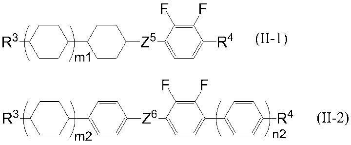
本発明の液晶表示装置における液晶層は、一般式(II-1)で表される化合物を1種又は2種以上含有することができるが、1種~6種含有することが好ましく、2種~5種含有することが好ましく、3種又は4種含有することが好ましい。
本発明の液晶表示装置における液晶層は、一般式(II-2)で表される化合物を1種又は2種以上含有することができるが、1種~6種含有することが好ましく、2種~5種含有することが好ましく、3種又は4種含有することが好ましい。

一般式(II-1a)及び一般式(II-1c)においてR3は、一般式(II-1)における同様の実施態様が好ましい。R4aは炭素原子数1~3のアルキル基が好ましく、炭素原子数1又は2のアルキル基がより好ましく、炭素原子数2のアルキル基が特に好ましい。
一般式(II-1a)~一般式(II-1d)の中でも、誘電率異方性の絶対値を増大するためには、一般式(II-1a)及び一般式(II-1c)が好ましく、一般式(II-1a)が好ましい。
本発明の液晶表示装置における液晶層は、一般式(II-1a)~一般式(II-1d)で表される化合物を1種又は2種以上含有することが好ましく、1種又は2種含有することが好ましく、一般式(II-1a)で表される化合物を1種又は2種含有することが好ましい。

一般式(II-1e)及び一般式(II-1g)においてR3は、一般式(II-1)における同様の実施態様が好ましい。R4bは炭素原子数1~3のアルキル基が好ましく、炭素原子数1又は2のアルキル基がより好ましく、炭素原子数2のアルキル基が特に好ましい。
一般式(II-1f)及び一般式(II-1h)においてR3は、一般式(II-1)における同様の実施態様が好ましい。R4bは炭素原子数1~3のアルキル基が好ましく、炭素原子数1又は3のアルキル基がより好ましく、炭素原子数3のアルキル基が特に好ましい。
一般式(II-1e)~一般式(II-1h)の中でも、誘電率異方性の絶対値を増大するためには、一般式(II-1e)及び一般式(II-1g)が好ましい。

一般式(II-2a)及び一般式(II-2c)においてR3は、一般式(II-2)における同様の実施態様が好ましい。R4cは炭素原子数1~3のアルキル基が好ましく、炭素原子数1又は2のアルキル基がより好ましく、炭素原子数2のアルキル基が特に好ましい。
一般式(II-2b)及び一般式(II-2d)においてR3は、一般式(II-2)における同様の実施態様が好ましい。R4cは炭素原子数1~3のアルキル基が好ましく、炭素原子数1又は3のアルキル基がより好ましく、炭素原子数3のアルキル基が特に好ましい。
一般式(II-2a)~一般式(II-2d)の中でも、誘電率異方性の絶対値を増大するためには、一般式(II-2a)及び一般式(II-2c)が好ましく、特に一般式(II-2a)が好ましい。
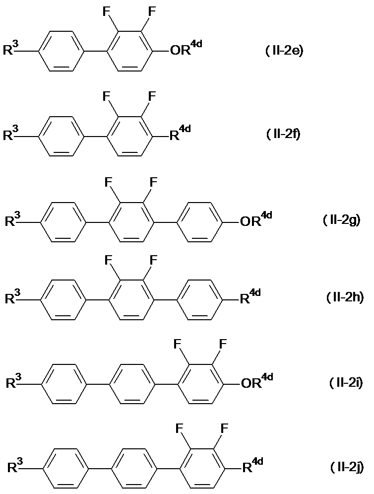
一般式(II-2e)、一般式(II-2g)及び一般式(II-2i)においてR3は、一般式(II-2)における同様の実施態様が好ましい。R4dは炭素原子数1~3のアルキル基が好ましく、炭素原子数1又は2のアルキル基がより好ましく、炭素原子数2のアルキル基が特に好ましい。
一般式(II-2f)、一般式(II-2h)及び一般式(II-2j)においてR3は、一般式(II-2)における同様の実施態様が好ましい。R4dは炭素原子数1~3のアルキル基が好ましく、炭素原子数1又は3のアルキル基がより好ましく、炭素原子数2のアルキル基が特に好ましい。
一般式(II-2e)~一般式(II-2i)の中でも、一般式(II-2e)及び一般式(II-2h)が好ましい。
で表される化合物を含有することもできる。
一般式(III)において、R7は炭素原子数1~8のアルキル基、炭素原子数2~8のアルケニル基、炭素原子数1~8のアルコキシ基又は炭素原子数2~8のアルケニルオキシ基を表すが、
Dがトランス-1,4-シクロヘキシレンを表す場合、炭素原子数1~5のアルキル基又は炭素原子数2~5のアルケニル基を表すことが好ましく、炭素原子数2~5のアルキル基又は炭素原子数2~4のアルケニル基を表すことがより好ましく、炭素原子数3~5のアルキル基又は炭素原子数2又は3のアルケニル基を表すことがさらに好ましく、炭素原子数3のアルキル基を表すことが特に好ましく、
Dがフッ素置換されていてもよい、1,4-フェニレン基を表す場合、炭素原子数1~5のアルキル基又は炭素原子数4又は5のアルケニル基を表すことが好ましく、炭素原子数2~5のアルキル基又は炭素原子数4のアルケニル基を表すことがより好ましく、炭素原子数2~4のアルキル基を表すことがさらに好ましい。
Fがトランス-1,4-シクロヘキシレンを表す場合、炭素原子数1~5のアルキル基又は炭素原子数2~5のアルケニル基を表すことが好ましく、炭素原子数2~5のアルキル基又は炭素原子数2~4のアルケニル基を表すことがより好ましく、炭素原子数3~5のアルキル基又は炭素原子数2又は3のアルケニル基を表すことがさらに好ましく、炭素原子数3のアルキル基を表すことが特に好ましく、
Fがフッ素置換されていてもよい、1,4-フェニレン基を表す場合、炭素原子数1~5のアルキル基又は炭素原子数4又は5のアルケニル基を表すことが好ましく、炭素原子数2~5のアルキル基又は炭素原子数4のアルケニル基を表すことがより好ましく、炭素原子数2~4のアルキル基を表すことがさらに好ましい。
この場合においても、炭素原子数4のアルケニル基がさらに好ましい。
nは0、1又は2を表すが、0又は1を表すことが好ましい。また、Z2が単結合以外の置換基を表す場合、1を表すことが好ましい。


一般式(III)で表される化合物は、nが2を表す場合、負の誘電率異方性を大きくする観点からは、一般式(III-2a)~一般式(III-2h)で表される化合物が好ましく、応答速度を速くする観点からは、一般式(III-2j)~一般式(III-2l)で表される化合物が好ましい。


一般式(III)で表される化合物は、nが0を表す場合、応答速度を速くする観点からは、一般式(III-3b)で表される化合物が好ましい。
R7は炭素原子数2~5のアルキル基が好ましく、炭素原子数3のアルキル基がより好ましい。R8は炭素原子数1~3のアルコキシ基が好ましく、炭素原子数2のアルコキシ基がより好ましい。
誘電率異方性は、25℃において、-2.0から-6.0であることが好ましく、-2.5から-5.0であることがより好ましく、-2.5から-4.0であることが特に好ましい。
屈折率異方性は、25℃において、0.08から0.13であることが好ましいが、0.09から0.12であることがより好ましい。更に詳述すると、薄いセルギャップに対応する場合は0.10から0.12であることが好ましく、厚いセルギャップに対応する場合は0.08から0.10であることが好ましい。
回転粘度(γ1)は150以下が好ましく、130以下がより好ましく、120以下が特に好ましい。

Zは、13000以下が好ましく、12000以下がより好ましく、11000以下が特に好ましい。
本発明の液晶表示装置における液晶層は、アクティブマトリクス表示素子に使用する場合においては、1012(Ω・m)以上の比抵抗を有することが必要であり、1013(Ω・m)が好ましく、1014(Ω・m)以上がより好ましい。

Sp1及びSp2はそれぞれ独立して、単結合、炭素原子数1~8のアルキレン基又は-O-(CH2)s-(式中、sは2から7の整数を表し、酸素原子は芳香環に結合するものとする。)を表し、
Z1は-OCH2-、-CH2O-、-COO-、-OCO-、-CF2O-、-OCF2-、-CH2CH2-、-CF2CF2-、-CH=CH-COO-、-CH=CH-OCO-、-COO-CH=CH-、-OCO-CH=CH-、-COO-CH2CH2-、-OCO-CH2CH2-、-CH2CH2-COO-、-CH2CH2-OCO-、-COO-CH2-、-OCO-CH2-、-CH2-COO-、-CH2-OCO-、-CY1=CY2-(式中、Y1及びY2はそれぞれ独立して、フッ素原子又は水素原子を表す。)、-C≡C-又は単結合を表し、
Cは1,4-フェニレン基、トランス-1,4-シクロヘキシレン基又は単結合を表し、式中の全ての1,4-フェニレン基は、任意の水素原子がフッ素原子により置換されていても良い。)で表されるニ官能モノマーが好ましい。
Sp1及びSp2はそれぞれ独立して、単結合、炭素原子数1~8のアルキレン基又は-O-(CH2)s-を表すが、PSA表示素子においては少なくとも一方が単結合であることが好ましく、共に単結合を表す化合物又は一方が単結合でもう一方が炭素原子数1~8のアルキレン基又は-O-(CH2)s-を表す態様が好ましい。この場合1~4のアルキル基が好ましく、sは1~4が好ましい。
Cは任意の水素原子がフッ素原子により置換されていても良い1,4-フェニレン基、トランス-1,4-シクロヘキシレン基又は単結合を表すが、1,4-フェニレン基又は単結合が好ましい。Cが単結合以外の環構造を表す場合、Z1は単結合以外の連結基も好ましく、Cが単結合の場合、Z1は単結合が好ましい。
一般式(V)において、Cが単結合を表し、環構造が二つの環で形成される場合において、次の式(Va-1)から式(Va-5)を表すことが好ましく、式(Va-1)から式(Va-3)を表すことがより好ましく、式(Va-1)を表すことが特に好ましい。

これらの骨格を含む重合性化合物は重合後の配向規制力がPSA型液晶表示素子に最適であり、良好な配向状態が得られることから、表示ムラが抑制されるか、又は、全く発生しない。

重合性モノマーを添加する場合において、重合開始剤が存在しない場合でも重合は進行するが、重合を促進するために重合開始剤を含有していてもよい。重合開始剤としては、ベンゾインエーテル類、ベンゾフェノン類、アセトフェノン類、ベンジルケタール類、アシルフォスフィンオキサイド類等が挙げられる。また、保存安定性を向上させるために、安定剤を添加しても良い。使用できる安定剤としては、例えば、ヒドロキノン類、ヒドロキノンモノアルキルエーテル類、第三ブチルカテコール類、ピロガロール類、チオフェノール類、ニトロ化合物類、β-ナフチルアミン類、β-ナフトール類、ニトロソ化合物等が挙げられる。
(重合性液晶化合物)
本発明の重合性官能基を有する液晶化合物(重合性液晶化合物)は、他の液晶化合物との組成物において液晶性を示す。尚、重合性液晶化合物単独では、液晶性を示さなくてもよい。
例えば、Handbook of Liquid Crystals(D.Demus,J.W.Goodby,G.W.Gray,H.W.Spiess,V.Vill編集、Wiley-VCH社発行,1998年)、季刊化学総説No.22、液晶の化学(日本化学会編,1994年)、あるいは、特開平7-294735号公報、特開平8-3111号公報、特開平8-29618号公報、特開平11-80090号公報、特開平11-116538号公報、特開平11-148079号公報、等に記載されているような、1,4-フェニレン基1,4-シクロヘキレン基等の構造が複数繋がったメソゲンと呼ばれる剛直な部位と、ビニル基、アクリル基、(メタ)アクリル基といった重合性官能基を有する棒状重合性液晶化合物、あるいは特開2004-2373号公報、特開2004-99446号公報に記載されているようなマレイミド基を有する棒状重合性液晶化合物が挙げられる。中でも、重合性基を有する棒状液晶化合物が、液晶温度範囲として室温前後の低温を含むものを作りやすく好ましい。
また、本発明の重合性液晶組成物は、1種類以上の重合性液晶化合物及び、重合開始剤を含有し、更に必要に応じて、界面活性剤、その他の添加剤で構成され、コレステリック液晶にする場合は、更にキラル化合物を含有する。
2つ以上の重合性官能基を有する液晶化合物は、具体的には以下の一般式(1)で表される化合物が好ましい。
MGで表されるメソゲン基又はメソゲン性支持基は、一般式(1-b)
置換基として1個以上のF、Cl、CF3、OCF3、CN基、炭素原子数1~8のアルキル基、アルコキシ基、アルカノイル基、アルカノイルオキシ基、炭素原子数2~8のアルケニル基、アルケニルオキシ基、アルケノイル基、アルケノイルオキシ基、又は、一般式(1-c)で表される1個以上の置換基
Z0、Z1、Z2、Z3、Z4、及びZ5はそれぞれ独立して、-COO-、-OCO-、-CH2 CH2-、-OCH2-、-CH2O-、-CH=CH-、-C≡C-、-CH=CHCOO-、-OCOCH=CH-、-CH2CH2COO-、-CH2CH2OCO-、-COOCH2CH2-、-OCOCH2CH2-、-CONH-、-NHCO-、炭素数2~10のハロゲン原子を有してもよいアルキル基又は単結合を表し、
n、l及びkはそれぞれ独立して0又は1を表し、0≦n+l+k≦3を表す。)で表される。但し、式中、重合性官能基は2つ以上存在する。

2つ以上の重合性官能基を有する液晶化合物は、1種又は2種以上用いることができるが、1種~6種が好ましく、2種~5種がより好ましい。
2つ以上の重合性官能基を有する液晶化合物の含有量は、重合性液晶組成物の内、25~100質量%含有することが好ましく、30 ~100質量%含有することがより好ましく、35~100質量%含有することが特に好ましい。
置換基として1個以上のF、Cl、CF3、OCF3、CN基、炭素原子数1~8のアルキル基、アルコキシ基、アルカノイル基、アルカノイルオキシ基、炭素原子数2~8のアルケニル基、アルケニルオキシ基、アルケノイル基、アルケノイルオキシ基を表す。また、Z0、Z1、Z2、Z3、Z4、及びZ5はそれぞれ独立して、-COO-、-OCO-、-CH2 CH2-、-OCH2-、-CH2O-、-CH=CH-、-C≡C-、-CH=CHCOO-、-OCOCH=CH-、-CH2CH2COO-、-CH2CH2OCO-、-COOCH2CH2-、-OCOCH2CH2-、-CONH-、-NHCO-、炭素数2~10のハロゲン原子を有してもよいアルキル基又は単結合を表し、
n、l及びkはそれぞれ独立して0又は1を表し、0≦n+l+k≦3を表す。
n、l及びkはそれぞれ独立して、0又は1を表し、0≦n+l+k≦3を表す。

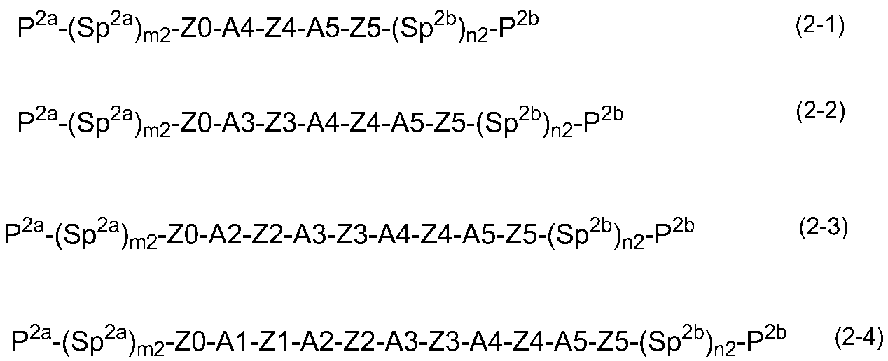

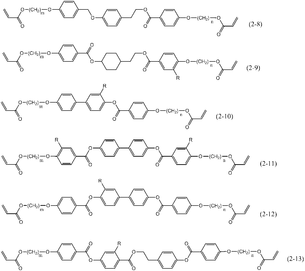

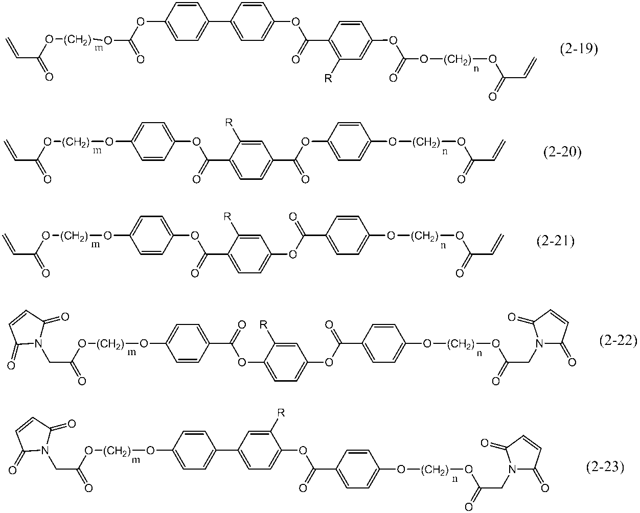

2つの重合性官能基を有する液晶化合物の含有量は、重合性組成物の内、25~100質量%含有することが好ましく、30~100質量%含有することがより好ましく、35~100質量%含有することが特に好ましい。
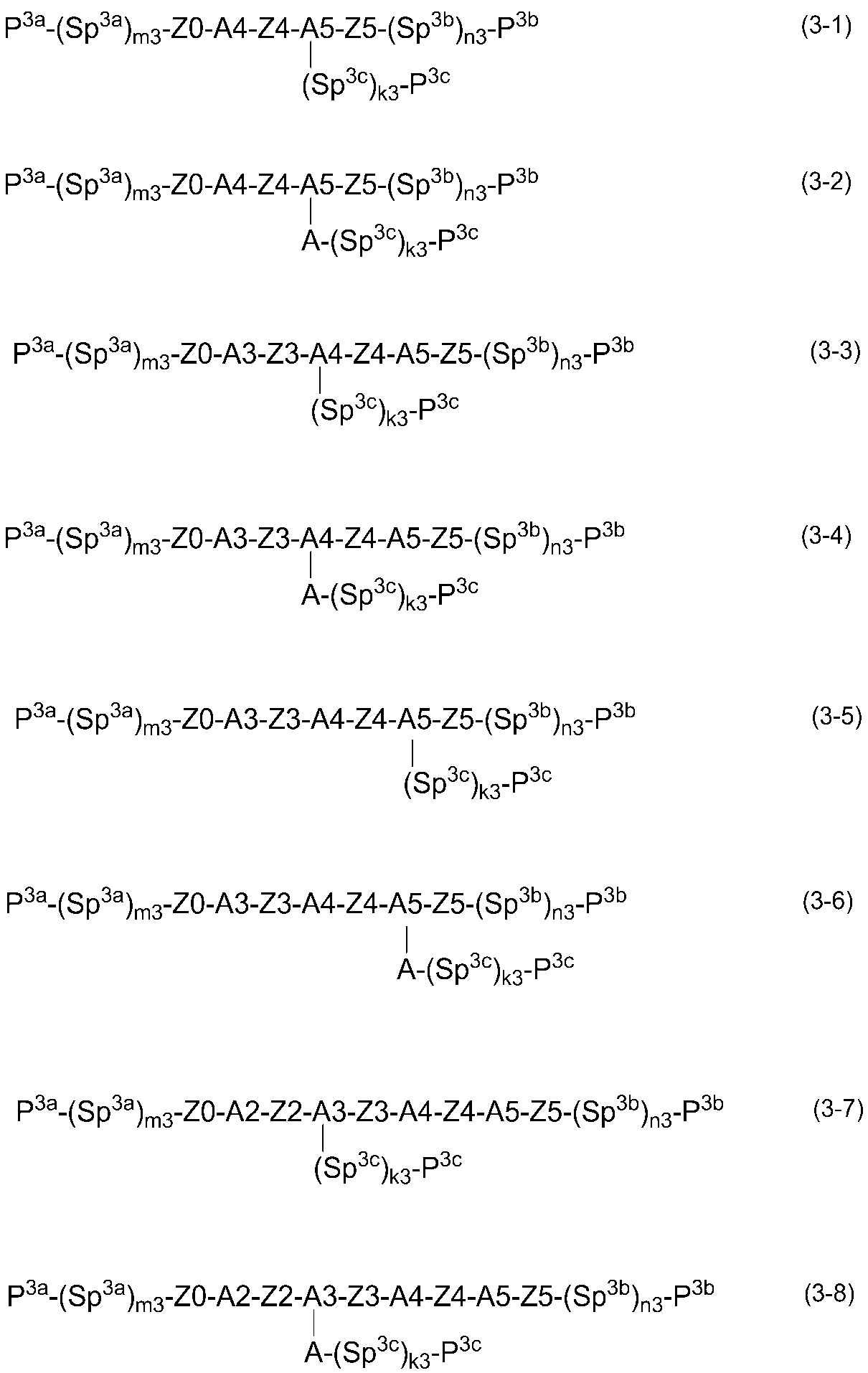


3つの重合性官能基を有する液晶化合物の含有量は、重合性液晶組成物の内、0~80質量%含有することが好ましく、0~70質量%含有することがより好ましく、0~60質量%含有することが特に好ましい。
1つの重合性官能基を有する液晶性化合物は、具体的には、以下の一般式(4)で表される化合物が好ましい。
R4は、水素原子、ハロゲン原子、シアノ基又は炭素原子数1~18のアルキル基を表すが、該アルキル基は1つ以上のハロゲン原子又はCNにより置換されていても良く、この基中に存在する1つのCH2基又は隣接していない2つ以上のCH2基はそれぞれ相互に独立して、酸素原子が相互に直接結合しない形で、-O-、-S-、-NH-、-N(CH3)-、-CO-、-COO-、-OCO-、-OCOO-、-SCO-、-COS-又は-C≡C-により置き換えられていても良い。

n、l及びkはそれぞれ独立して、0又は1を表し、0≦n+l+k≦3を表す。

一般式(4)で表される化合物としては、以下の式(4-5)~(4-31)で表される化合物が挙げられるが、これらに限定される訳ではない。
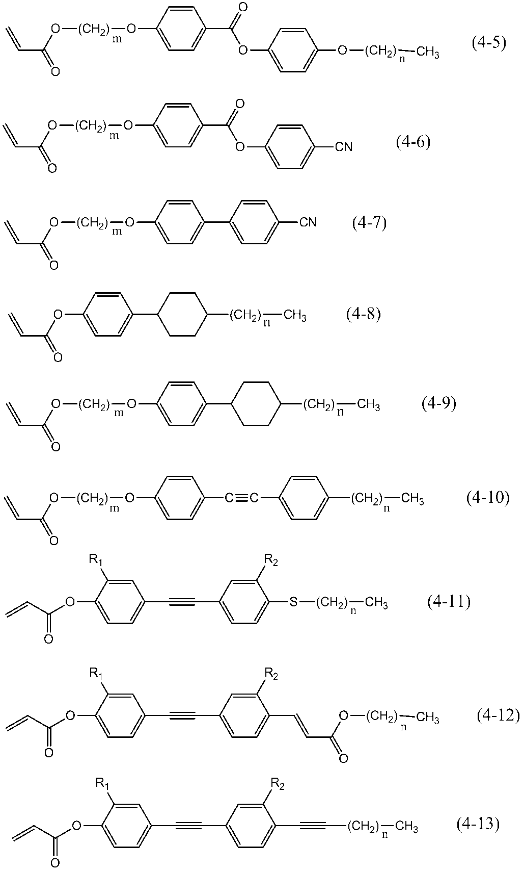


1つの重合性官能基を有する液晶化合物の含有量は、重合性液晶組成物の内、0質量%以上が好ましく、10質量%以上がより好ましく、20質量%以上が特に好ましく、75質量%以下が好ましく、70質量%以下がより好ましく、65質量%以下が特に好ましい。
(キラル化合物)
本発明における重合性液晶組成物には、キラルネマチック相を得ることを目的としてキラル化合物を配合してもよい。キラル化合物のなかでも、分子中に重合性官能基を有する化合物が特に好ましい。尚、本発明のキラル化合物は液晶性を示してもよく、非液晶性であってもよい。
キラル化合物の一般式の一例として、一般式(5-1)~(5-4)を挙げることができるが、下記の一般式に限定されるわけではない。

A1、A2、A3、A4、及びA5はそれぞれ独立して、1,4-フェニレン基、1,4-シクロヘキシレン基、1,4-シクロヘキセニル基、テトラヒドロピラン-2,5-ジイル基、1,3-ジオキサン-2,5-ジイル基、テトラヒドロチオピラン-2,5-ジイル基、1,4-ビシクロ(2,2,2)オクチレン基、デカヒドロナフタレン-2,6-ジイル基、ピリジン-2,5-ジイル基、ピリミジン-2,5-ジイル基、ピラジン-2,5-ジイル基、チオフェン-2,5-ジイル基-、1,2,3,4-テトラヒドロナフタレン-2,6-ジイル基、2,6-ナフチレン基、フェナントレン-2,7-ジイル基、9,10-ジヒドロフェナントレン-2,7-ジイル基、1,2,3,4,4a,9,10a-オクタヒドロフェナントレン-2,7-ジイル基、1,4-ナフチレン基、ベンゾ[1,2-b:4,5-b‘]ジチオフェン-2,6-ジイル基、ベンゾ[1,2-b:4,5-b‘]ジセレノフェン-2,6-ジイル基、[1]ベンゾチエノ[3,2-b]チオフェン-2,7-ジイル基、[1]ベンゾセレノフェノ[3,2-b]セレノフェン-2,7-ジイル基、又はフルオレン-2,7-ジイル基を表し、n、l及びkはそれぞれ独立して、0又は1を表し、0≦n+l+k≦3となり、
m5は0又は1を表し、
R5a及びR5bは、水素原子、ハロゲン原子、シアノ基又は炭素原子数1~18のアルキル基を表すが、該アルキル基は1つ以上のハロゲン原子又はCNにより置換されていても良く、この基中に存在する1つのCH2基又は隣接していない2つ以上のCH2基はそれぞれ相互に独立して、酸素原子が相互に直接結合しない形で、-O-、-S-、-NH-、-N(CH3)-、-CO-、-COO-、-OCO-、-OCOO-、-SCO-、-COS-又は-C≡C-により置き換えられていても良く、
あるいはR5a及びR5bは一般式(5-a)
P5aは、下記の式(P-1)から式(P-20)で表される重合性基から選ばれる置換基を表すのが好ましい。


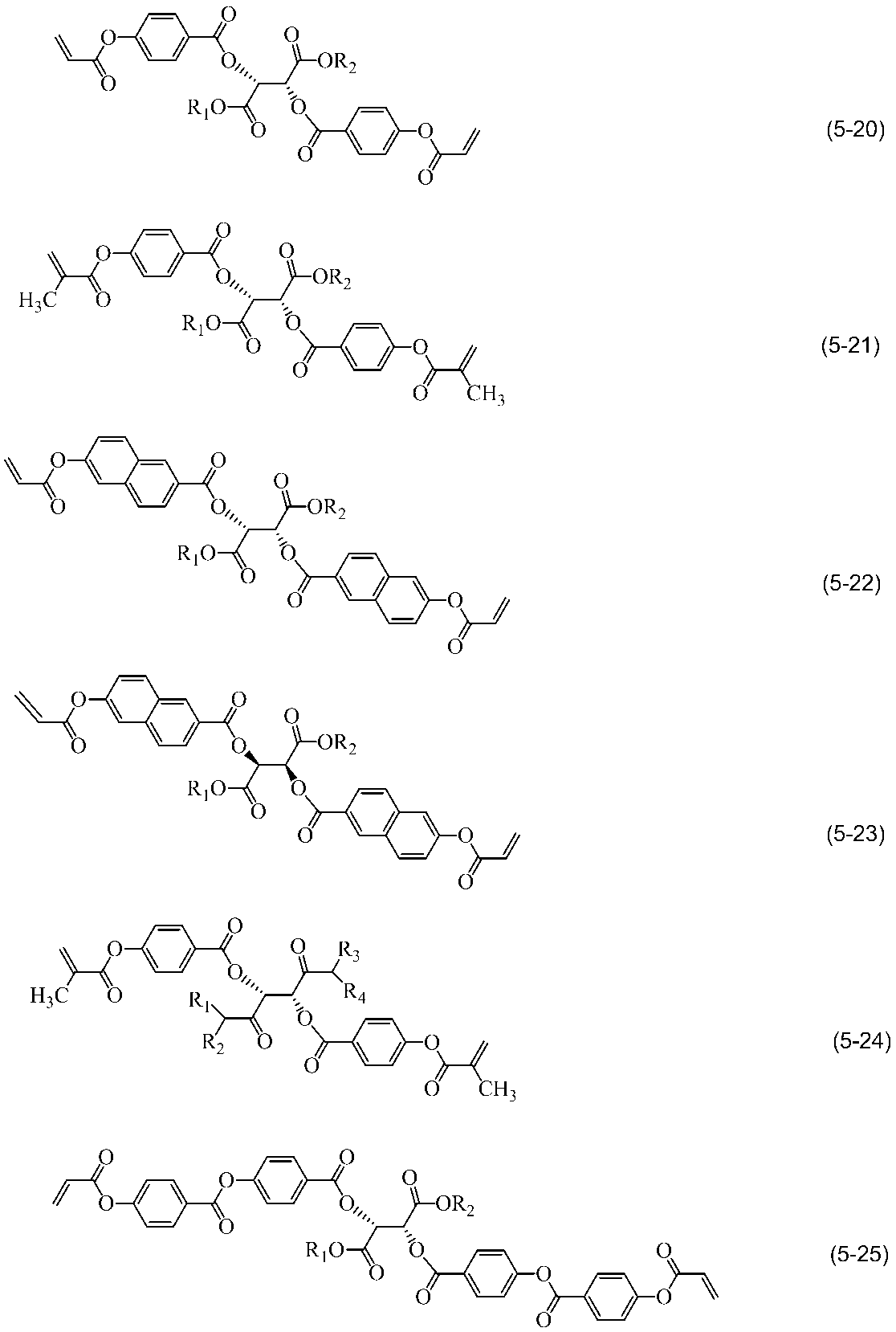
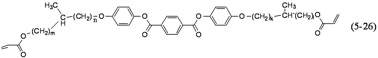
本発明における重合性液晶組成物に有機溶剤を添加し、重合性液晶組成物溶液として使用してもよい。用いる有機溶剤としては特に限定はないが、重合性液晶化合物が良好な溶解性を示す有機溶剤が好ましく、100℃以下の温度で乾燥できる有機溶剤であることが好ましい。そのような溶剤としては、例えば、トルエン、キシレン、クメン、メシチレン等の芳香族系炭化水素、酢酸メチル、酢酸エチル、酢酸プロピル、酢酸ブチル等のエステル系溶剤、メチルエチルケトン、メチルイソブチルケトン、シクロヘキサノン、シクロペンタノン等のケトン系溶剤、テトラヒドロフラン、1,2-ジメトキシエタン、アニソール等のエーテル系溶剤、N,N-ジメチルホルムアミド、N-メチル-2-ピロリドン、等のアミド系溶剤、プロピレングリコールモノメチルエーテルアセテート、ジエチレングリコールモノメチルエーテルアセテート、γ-ブチロラクトン及びクロロベンゼン等が挙げられる。これらは、単独で使用することもできるし、2種類以上混合して使用することもできるが、ケトン系溶剤、エーテル系溶剤、エステル系溶剤及び芳香族炭化水素系溶剤のうちのいずれか1種類以上を用いることが溶液安定性の点から好ましい。
有機溶剤に重合性液晶化合物を溶解する際には、均一に溶解させるために、加熱攪拌することが好ましい。加熱攪拌時の加熱温度は、用いる重合性液晶化合物の有機溶剤に対する溶解性を考慮して適宜調節すればよいが、生産性の点から15℃~110℃が好ましく、15℃~105℃がより好ましく、15℃~100℃がさらに好ましく、20℃~90℃とするのが特に好ましい。
重合性液晶組成物溶液を調製する際の攪拌回転数は、用いる攪拌装置により適宜調整することが好ましいが、均一な重合性液晶組成物溶液とするために攪拌回転数を10rpm~1000rpmとするのが好ましく、50rpm~800rpmとするのがより好ましく、150rpm~600rpmとするのが特に好ましい。
本発明における重合性液晶組成物の溶液安定性を高めるため、重合禁止剤を添加することが好ましい。重合禁止剤としては、フェノール系化合物、キノン系化合物、アミン系化合物、チオエーテル系化合物、ニトロソ化合物、等が挙げられる。
本発明における重合性液晶組成物の溶液安定性を高めるため、酸化防止剤等を添加することが好ましい。そのような化合物として、ヒドロキノン誘導体、ニトロソアミン系重合禁止剤、ヒンダードフェノール系酸化防止剤等が挙げられ、より具体的には、tert-ブチルハイドロキノン、メチルハイドロキノン、和光純薬工業社の「Q-1300」、「Q-1301」、BASF社の「IRGANOX1010」、「IRGANOX1035」、「IRGANOX1076」、「IRGANOX1098」、「IRGANOX1135」、「IRGANOX1330」、「IRGANOX1425」、「IRGANOX1520」、「IRGANOX1726」、「IRGANOX245」、「IRGANOX259」、「IRGANOX3114」、「IRGANOX3790」、「IRGANOX5057」、「IRGANOX565」等々があげられる。
酸化防止剤の添加量は重合性液晶組成物に対して0.01~2.0質量%であることが好ましく、0.05~1.0質量%であることがより好ましい。
本発明における重合性液晶組成物は光重合開始剤を含有することが好ましい。光重合開始剤は少なくとも1種類以上含有することが好ましい。具体的には、BASF社製の「イルガキュア651」、「イルガキュア184」、「ダロキュア1173」、「イルガキュア907」、「イルガキュア127」、「イルガキュア369」、「イルガキュア379」、「イルガキュア819」、「イルガキュア2959」、「イルガキュア1800」、「イルガキュア250」、「イルガキュア754」、「イルガキュア784」、「イルガキュアOXE01」、「イルガキュアOXE02」、「ルシリンTPO」、「ダロキュア1173」、「ダロキュアMBF」やLAMBSON社製の「エサキュア1001M」、「エサキュアKIP150」、「スピードキュアBEM」、「スピードキュアBMS」、「スピードキュアMBP」、「スピードキュアPBZ」、「スピードキュアITX」、「スピードキュアDETX」、「スピードキュアEBD」、「スピードキュアMBB」、「スピードキュアBP」や日本化薬社製の「カヤキュアDMBI」、日本シイベルヘグナー社製(現DKSH社)の「TAZ-A」、ADEKA社製の「アデカオプトマーSP-152」、「アデカオプトマーSP-170」、「アデカオプトマーN-1414」、「アデカオプトマーN-1606」、「アデカオプトマーN-1717」、「アデカオプトマーN-1919」等が挙げられる。
熱重合の際に使用する熱重合開始剤としては公知慣用のものが使用でき、例えば、メチルアセトアセテイトパーオキサイド、キュメンハイドロパーオキサイド、ベンゾイルパーオキサイド、ビス(4-t-ブチルシクロヘキシル)パ-オキシジカーボネイト、t-ブチルパーオキシベンゾエイト、メチルエチルケトンパーオキサイド、1,1-ビス(t-ヘキシルパ-オキシ)3,3,5-トリメチルシクロヘキサン、p-ペンタハイドロパーオキサイド、t-ブチルハイドロパーオキサイド、ジクミルパーオキサイド、イソブチルパーオキサイド、ジ(3-メチル-3-メトキシブチル)パーオキシジカーボネイト、1,1-ビス(t-ブチルパーオキシ)シクロヘキサン等の有機過酸化物、2,2’-アゾビスイソブチロニトリル、2,2’-アゾビス(2,4-ジメチルバレロニトリル)等のアゾニトリル化合物、2,2’-アゾビス(2-メチル-N-フェニルプロピオン-アミヂン)ジハイドロクロライド等のアゾアミヂン化合物、2,2’アゾビス{2-メチル-N-[1,1-ビス(ヒドロキシメチル)-2-ヒドロキシエチル]プロピオンアミド}等のアゾアミド化合物、2,2’アゾビス(2,4,4-トリメチルペンタン)等のアルキルアゾ化合物等を使用することができる。熱重合開始剤の含有利量は0.1~10質量が好ましく、1~6質量%が特に好ましい。これらは、単独で使用することもできるし、2種類以上混合して使用することもできる。
本発明における重合性液晶組成物は、光学異方体とした場合の膜厚むらを低減させるために界面活性剤を少なくとも1種類以上含有してもよい。含有することができる界面活性剤としては、アルキルカルボン酸塩、アルキルリン酸塩、アルキルスルホン酸塩、フルオロアルキルカルボン酸塩、フルオロアルキルリン酸塩、フルオロアルキルスルホン酸塩、ポリオキシエチレン誘導体、フルオロアルキルエチレンオキシド誘導体、ポリエチレングリコール誘導体、アルキルアンモニウム塩、フルオロアルキルアンモニウム塩類等をあげることができ、特に含フッ素界面活性剤が好ましい。
「フタージェント100」、「フタージェント100C」、「フタージェント110」、「フタージェント150」、「フタージェント150CH」、「フタージェント100A-K」、「フタージェント300」、「フタージェント310」、「フタージェント320」、「フタージェント400SW」、「フタージェント251」、「フタージェント215M」、「フタージェント212M」、「フタージェント215M」、「フタージェント250」、「フタージェント222F」、「フタージェント212D」、「FTX-218」、「フタージェント209F」、「フタージェント245F」、「フタージェント208G」、「フタージェント240G」、「フタージェント212P」、「フタージェント220P」、「フタージェント228P」、「DFX-18」、「フタージェント601AD」、「フタージェント602A」、「フタージェント650A」、「フタージェント750FM」、「FTX-730FM」、「フタージェント730FL」、「フタージェント710FS」、「フタージェント710FM」、「フタージェント710FL」、「フタージェント750LL」、「FTX-730LS」、「フタージェント730LM」、(以上、株式会社ネオス製)、
「BYK-300」、「BYK-302」、「BYK-306」、「BYK-307」、「BYK-310」、「BYK-315」、「BYK-320」、「BYK-322」、「BYK-323」、「BYK-325」、「BYK-330」、「BYK-331」、「BYK-333」、「BYK-337」、「BYK-340」、「BYK-344」、「BYK-370」、「BYK-375」、「BYK-377」、「BYK-350」、「BYK-352」、「BYK-354」、「BYK-355」、「BYK-356」、「BYK-358N」、「BYK-361N」、「BYK-357」、「BYK-390」、「BYK-392」、「BYK-UV3500」、「BYK-UV3510」、「BYK-UV3570」、「BYK-Silclean3700」(以上、BYK株式会社製)、
「TEGO Rad2100」、「TEGO Rad2011」、「TEGO Rad2200N」、「TEGO Rad2250」、「TEGO Rad2300」、「TEGO Rad2500」、「TEGO Rad2600」、「TEGO Rad2650」、「TEGO Rad2700」、「TEGO Flow300」、「TEGO Flow370」、「TEGO Flow425」、「TEGO Flow ATF2」、「TEGO Flow ZFS460」、「TEGO Glide100」、「TEGO Glide110」、「TEGO Glide130」、「TEGO Glide410」、「TEGO Glide411」、「TEGO Glide415」、「TEGO Glide432」、「TEGO Glide440」、「TEGO Glide450」、「TEGO Glide482」、「TEGO Glide A115」、「TEGO Glide B1484」、「TEGO Glide ZG400」、「TEGO Twin4000」、「TEGO Twin4100」、「TEGO Twin4200」、「TEGO Wet240」、「TEGO Wet250」、「TEGO Wet260」、「TEGO Wet265」、「TEGO Wet270」、「TEGO Wet280」、「TEGO Wet500」、「TEGO Wet505」、「TEGO Wet510」、「TEGO Wet520」、「TEGO Wet KL245」、(以上、エボニック・インダストリーズ株式会社製)、「FC-4430」、「FC-4432」(以上、スリーエムジャパン株式会社製)、「ユニダインNS」(以上、ダイキン工業株式会社製)、「サーフロンS-241」、「サーフロンS-242」、「サーフロンS-243」、「サーフロンS-420」、「サーフロンS-611」、「サーフロンS-651」、「サーフロンS-386」(以上、AGCセイミケミカル株式会社製)、「DISPARLON OX-880EF」、「DISPARLON OX-881」、「DISPARLON OX-883」、「DISPARLON OX-77EF」、「DISPARLON OX-710」、「DISPARLON 1922」、「DISPARLON 1927」、「DISPARLON 1958」、「DISPARLON P-410EF」、「DISPARLON P-420」、「DISPARLON P-425」、「DISPARLON PD-7」、「DISPARLON 1970」、「DISPARLON 230」、「DISPARLON LF-1980」、「DISPARLON LF-1982」、「DISPARLON LF-1983」、「DISPARLON LF-1084」、「DISPARLON LF-1985」、「DISPARLON LHP-90」、「DISPARLON LHP-91」、「DISPARLON LHP-95」、「DISPARLON LHP-96」、「DISPARLON OX-715」、「DISPARLON 1930N」、「DISPARLON 1931」、「DISPARLON 1933」、「DISPARLON 1934」、「DISPARLON 1711EF」、「DISPARLON 1751N」、「DISPARLON 1761」、「DISPARLON LS-009」、「DISPARLON LS-001」、「DISPARLON LS-050」(以上、楠本化成株式会社製)、「PF-151N」、「PF-636」、「PF-6320」、「PF-656」、「PF-6520」、「PF-652-NF」、「PF-3320」(以上、OMNOVA SOLUTIONS社製)、「ポリフローNo.7」、「ポリフローNo.50E」、「ポリフローNo.50EHF」、「ポリフローNo.54N」、「ポリフローNo.75」、「ポリフローNo.77」、「ポリフローNo.85」、「ポリフローNo.85HF」、「ポリフローNo.90」、「ポリフローNo.90D-50」、「ポリフローNo.95」、「ポリフローNo.99C」、「ポリフローKL-400K」、「ポリフローKL-400HF」、「ポリフローKL-401」、「ポリフローKL-402」、「ポリフローKL-403」、「ポリフローKL-404」、「ポリフローKL-100」、「ポリフローLE-604」、「ポリフローKL-700」、「フローレンAC-300」、「フローレンAC-303」、「フローレンAC-324」、「フローレンAC-326F」、「フローレンAC-530」、「フローレンAC-903」、「フローレンAC-903HF」、「フローレンAC-1160」、「フローレンAC-1190」、「フローレンAC-2000」、「フローレンAC-2300C」、「フローレンAO-82」、「フローレンAO-98」、「フローレンAO-108」(以上、共栄社化学株式会社製)、「L-7001」、「L-7002」、「8032ADDITIVE」、「57ADDTIVE」、「L-7064」、「FZ-2110」、「FZ-2105」、「67ADDTIVE」、「8616ADDTIVE」(以上、東レ・ダウシリコーン株式会社製)等の例を挙げることができる。
また、上記界面活性剤を使用することで、本発明の重合性液晶組成物を光学異方体とした場合、空気界面のチルト角を効果的に減じることができるものもある。
本発明における重合性液晶組成物は、光学異方体とした場合の空気界面のチルト角を効果的に減じる効果を持つ、上記界面活性剤以外として、下記一般式(6)で表される繰り返し単位を有する重量平均分子量が100以上である化合物が挙げられる。
一般式(6)で表される好適な化合物として、例えばポリエチレン、ポリプロピレン、ポリイソブチレン、パラフィン、流動パラフィン、塩素化ポリプロピレン、塩素化パラフィン、塩素化流動パラフィン等を挙げることができる。
一般式(6)で表される化合物は、重合性化合物を有機溶剤に混合し加熱攪拌して重合性溶液を調製する工程において添加することが好ましいが、その後の、重合性溶液に光重合開始剤を混合する工程において添加してもよいし、両方の工程において添加してもよい。
一般式(6)で表される化合物の添加量は重合性液晶組成物溶液に対して、0.01~1質量%であることが好ましく、0.05~0.5質量%であることがより好ましい。

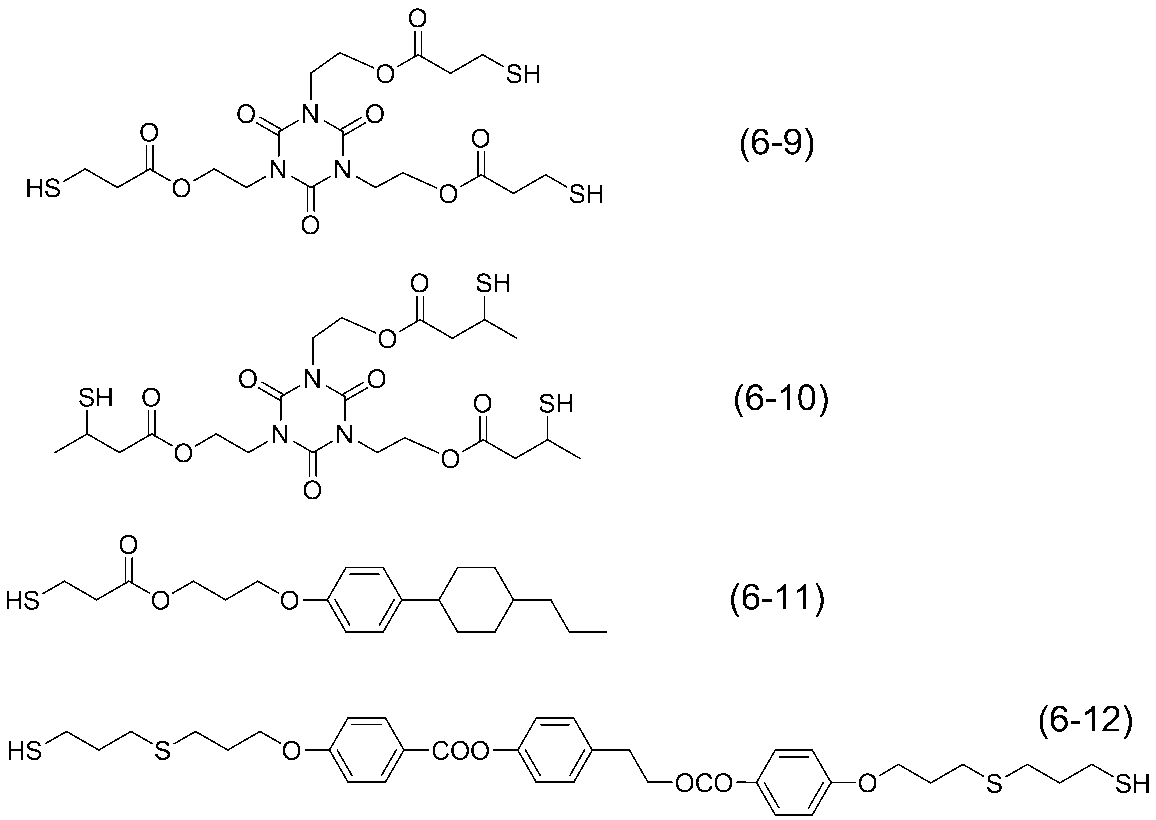
連鎖移動剤の添加量は重合性液晶組成物に対して、0.5~10質量%であることが好ましく、1.0~5.0質量%であることがより好ましい。
本発明の重合性混合物、又は重合性組成物には、目的に応じて他の添加剤、例えば、チキソ剤、紫外線吸収剤、赤外線吸収剤、抗酸化剤、表面処理剤等の添加剤を液晶の配向能を著しく低下させない程度添加することができる。
本発明における重合性液晶組成物を、配向機能を有する基材上に塗布し、本発明の重合性液晶組成物中の液晶分子を、スメクチック相、ネマチック相を保持した状態で均一に配向させ、重合させることによって、本発明の光学異方体が得られる。
ここで、ポジティブAプレートとは、重合性液晶組成物をホモジニアス配向させた、光学異方体を意味する。また、ネガティブCプレートとは、重合性液晶組成物をコレステリック配向させた、光学異方体を意味する。
また、液晶分子自体の複屈折を打ち消すために、第2の位相差層としては負の屈折率異方性を有する、いわゆるネガティブCプレートを使用することが好ましい。また、ポジティブAプレート上にネガティブCプレートを積層してもよい。
なお、厚み方向の屈折率異方性は、式(2)により定義される厚み方向位相差値Rthで表される。厚み方向位相差値Rthは、面内位相差値R0、遅相軸を傾斜軸として50
°傾斜して測定した位相差値R50、フィルムの厚みd、フィルムの平均屈折率n0を用いて、式(1)と次式(4)~(7)から数値計算によりnx、ny、nzを求め、これらを式(2)に代入して算出することができる。また、Nz係数=は、式(3)から算出することができる。以下、本明細書の他の記載において同様である。
Rth=[(nx+ny)/2-nz]×d (2)
Nz係数=(nx-nz)/(nx-ny) (3)
R50=(nx-ny’)×d/cos(φ) (4)
(nx+ny+nz)/3=n0 (5)
ここで、
φ=sin-1[sin(50°)/n0] (6)
ny’=ny×nz/[ny2×sin2(φ)+nz2×cos2(φ)]1/2 (7)
本発明における光学異方体に用いられる基材は、液晶デバイス、ディスプレイ、光学部品や光学フィルムに通常使用する基材であって、本発明の重合性組成物溶液の塗布後の乾燥時における加熱に耐えうる耐熱性を有する材料であれば、特に制限はない。そのような基材としては、ガラス基材、金属基材、セラミックス基材やプラスチック基材等の有機材料が挙げられる。特に基材が有機材料の場合、セルロース誘導体、ポリオレフィン、ポリエステル、ポリオレフィン、ポリカーボネート、ポリアクリレート、ポリアリレート、ポリエーテルサルホン、ポリイミド、ポリフェニレンスルフィド、ポリフェニレンエーテル、ナイロン又はポリスチレン等が挙げられる。中でもポリエステル、ポリスチレン、ポリオレフィン、セルロース誘導体、ポリアリレート、ポリカーボネート等のプラスチック基材が好ましい。基材の形状としては、平板の他、曲面を有するものであっても良い。これらの基材は、必要に応じて、電極層、反射防止機能、反射機能を有していてもよい。
本発明の重合性液晶組成物の塗布性や接着性向上のために、これらの基材の表面処理を行っても良い。表面処理として、オゾン処理、プラズマ処理、コロナ処理、シランカップリング処理などが挙げられる。
本発明における光学異方体を得るための塗布法としては、アプリケーター法、バーコーティング法、スピンコーティング法、ロールコーティング法、ダイレクトグラビアコーティング法、リバースグラビアコーティング法、フレキソコーティング法、インクジェット法、ダイコーティング法、キャップコーティング法、ディップコーティング法、スリットコーティング法等、公知慣用の方法を行うことができる。重合性液晶組成物を塗布後、乾燥させる。
本発明における重合性液晶組成物の重合操作については、重合性液晶組成物中の液晶化合物が基材に対して水平配向、垂直配向、又はハイブリッド配向、あるいはコレステリック配向(平面配向)した状態で一般に紫外線等の光照射、あるいは加熱によって行われる。重合を光照射で行う場合は、具体的には390nm以下の紫外光を照射することが好ましく、250~370nmの波長の光を照射することが最も好ましい。但し、390nm以下の紫外光により重合性組成物が分解などを引き起こす場合は、390nm以上の紫外光で重合処理を行ったほうが好ましい場合もある。この光は、拡散光で、かつ偏光していない光であることが好ましい。
本発明における重合性液晶組成物を重合させる方法としては、活性エネルギー線を照射する方法や熱重合法等が挙げられるが、室温で反応が進行することから活性エネルギー線を照射する方法が好ましく、中でも、操作が簡便なことから、紫外線等の光を照射する方法が好ましい。照射時の温度は、本発明の重合性液晶組成物が液晶相を保持できる温度とし、重合性液晶組成物の熱重合の誘起を避けるため、可能な限り50℃以下とすることが好ましい。尚、液晶組成物は、通常、昇温過程において、C(固相)-N(ネマチック)転移温度(以下、C-N転移温度と略す。)から、N-I転移温度範囲内で液晶相を示す。一方、降温過程においては、熱力学的に非平衡状態を取るため、C-N転移温度以下でも凝固せず液晶状態を保つ場合がある。この状態を過冷却状態という。本発明においては、過冷却状態にある液晶組成物も液晶相を保持している状態に含めるものとする。具体的には390nm以下の紫外光を照射することが好ましく、250~370nmの波長の光を照射することが最も好ましい。但し、390nm以下の紫外光により重合性組成物が分解などを引き起こす場合は、390nm以上の紫外光で重合処理を行ったほうが好ましい場合もある。この光は、拡散光で、かつ偏光していない光であることが好ましい。紫外線照射強度は、0.05kW/m2~10kW/m2の範囲が好ましい。特に、0.2kW/m2~2kW/m2の範囲が好ましい。紫外線強度が0.05kW/m2未満の場合、重合を完了させるのに多大な時間がかかる。一方、2kW/m2を超える強度では、重合性液晶組成物中の液晶分子が光分解する傾向にあることや、重合熱が多く発生して重合中の温度が上昇し、重合性液晶のオーダーパラメーターが変化して、重合後の塗膜のリタデーションに狂いが生じる可能性がある。
マスクを使用して特定の部分のみを紫外線照射で重合させた後、該未重合部分の配向状態を、電場、磁場又は温度等をかけて変化させ、その後該未重合部分を重合させると、異なる配向方向をもった複数の領域を有する光学異方体を得ることもできる。
また、マスクを使用して特定の部分のみを紫外線照射で重合させる際に、予め未重合状態の重合性液晶組成物に電場、磁場又は温度等をかけて配向を規制し、その状態を保ったままマスク上から光を照射して重合させることによっても、異なる配向方向をもった複数の領域を有する光学異方体を得ることができる。
また、上記基材には、本発明の重合性組成物溶液を塗布乾燥した際に重合性組成物が配向するように、配向膜が設けられていても良い。配向処理としては、延伸処理、ラビング処理、偏光紫外可視光照射処理、イオンビーム処理、基材へのSiO2の斜方蒸着処理、等が挙げられる。配向膜を用いる場合、配向膜は公知慣用のものが用いられる。そのような配向膜としては、ポリイミド、ポリシロキサン、ポリアミド、ポリビニルアルコール、ポリカーボネート、ポリスチレン、ポリフェニレンエーテル、ポリアリレート、ポリエチレンテレフタレート、ポリエーテルサルホン、エポキシ樹脂、エポキシアクリレート樹脂、アクリル樹脂、クマリン化合物、カルコン化合物、シンナメート化合物、フルギド化合物、アントラキノン化合物、アゾ化合物、アリールエテン化合物等の化合物が挙げられる。ラビングにより配向処理する化合物は、配向処理、もしくは配向処理の後に加熱工程を入れることで材料の結晶化が促進されるものが好ましい。ラビング以外の配向処理を行う化合物の中では光配向材料を用いることが好ましい。
本発明の液晶表示装置は、カラーフィルタを有していてもよい。カラーフィルタは、ブラックマトリックス及び少なくともRGB三色画素部から構成される。カラーフィルタ層の形成には、何れの方法を用いてもよい。一例によると、顔料担体とこれに分散させたカラー顔料とを含んだカラー着色組成物を塗布して所定パターンとし、これを硬化させることによって着色画素を得る工程を必要回数繰り返して、カラーフィルタ層を形成することができる。カラー着色組成物に含まれる顔料としては、有機顔料および/または無機顔料を使用することができる。カラー着色組成物は、1種の有機または無機顔料を含んでいてもよく、複数種の有機顔料および/または無機顔料を含んでいてもよい。顔料は、発色性が高く且つ耐熱性、特に耐熱分解性の高いことが好ましく、通常は有機顔料が用いられる。以下に、カラー着色組成物に使用可能な有機顔料の具体例を、カラーインデックス番号で示す。
カラー着色組成物は、顔料以外の着色成分をさらに含んでいてもよい。例えば、着色組成物は、十分な耐熱性を達成できるのであれば、染料を含有していてもよい。この場合、染料を用いた調色が可能である。
重量部が好ましく、0.1乃至30重量部の量で使用することがより好ましい。
性のある部位を含んでいる。樹脂型顔料分散剤は、顔料に吸着して顔料の顔料担体への分散性を安定化する。樹脂型顔料分散剤としては、例えば、ポリウレタン、ポリアクリレートなどのポリカルボン酸エステル、不飽和ポリアミド、ポリカルボン酸、ポリカルボン酸アミン塩、ポリカルボン酸部分アミン塩、ポリカルボン酸アンモニウム塩、ポリカルボン酸アルキルアミン塩、ポリシロキサン、長鎖ポリアミノアマイドリン酸塩および水酸基含有ポリカルボン酸エステル、これらの変性物、ポリ(低級アルキレンイミン)と遊離カルボキシル基を有するポリエステルとの反応により形成されたアミドおよびその塩などの油性分散剤;アクリル酸-スチレン共重合体、メタクリル酸-スチレン共重合体、アクリル酸-アクリル酸エステル共重合体、アクリル酸-メタクリル酸エステル共重合体、メタクリル酸-アクリル酸エステル共重合体、メタクリル酸-メタクリル酸エステル共重合体、スチレン-マレイン酸共重合体、ポリビニルアルコールおよびポリビニルピロリドンなどの水溶性樹脂若しくは水溶性高分子化合物;ポリエステル類、変性ポリアクリレート類、エチレンオキサイド/プロピレンオキサイド付加化合物、燐酸エステル類、またはそれらの2種以上を含んだ混合物を使用することができる。
また、カラーフィルタ層の表面にオーバーコートを塗布した平坦化層を設けてもよい。
本発明の液晶表示装置は、第一の基板と第二の基板上の液晶組成物と接する面には液晶組成物を配向させるために配向膜を有していても良い。
配向膜材料としては、ポリイミド、ポリアミド、BCB(ペンゾシクロブテンポリマー)、ポリビニルアルコールなどの透明性有機材料を用いることができ、特に、p-フェニレンジアミン、4,4’-ジアミノジフエニルメタンなどの脂肪族または脂環族ジアミン等のジアミン及びブタンテトラカルボン酸無水物や2,3,5-トリカルボキシシクロペンチル酢酸無水物等の脂肪族又は脂環式テトラカルボン酸無水物、ピロメリット酸二無水物等の芳香族テトラカルボン酸無水物から合成されるポリアミック酸をイミド化した、ポリイミド配向膜が好ましい。この場合の配向付与方法は、ラビングを用いることが一般的であるが、垂直配向膜等に使用する場合は配向を付与しないで使用することもできる。
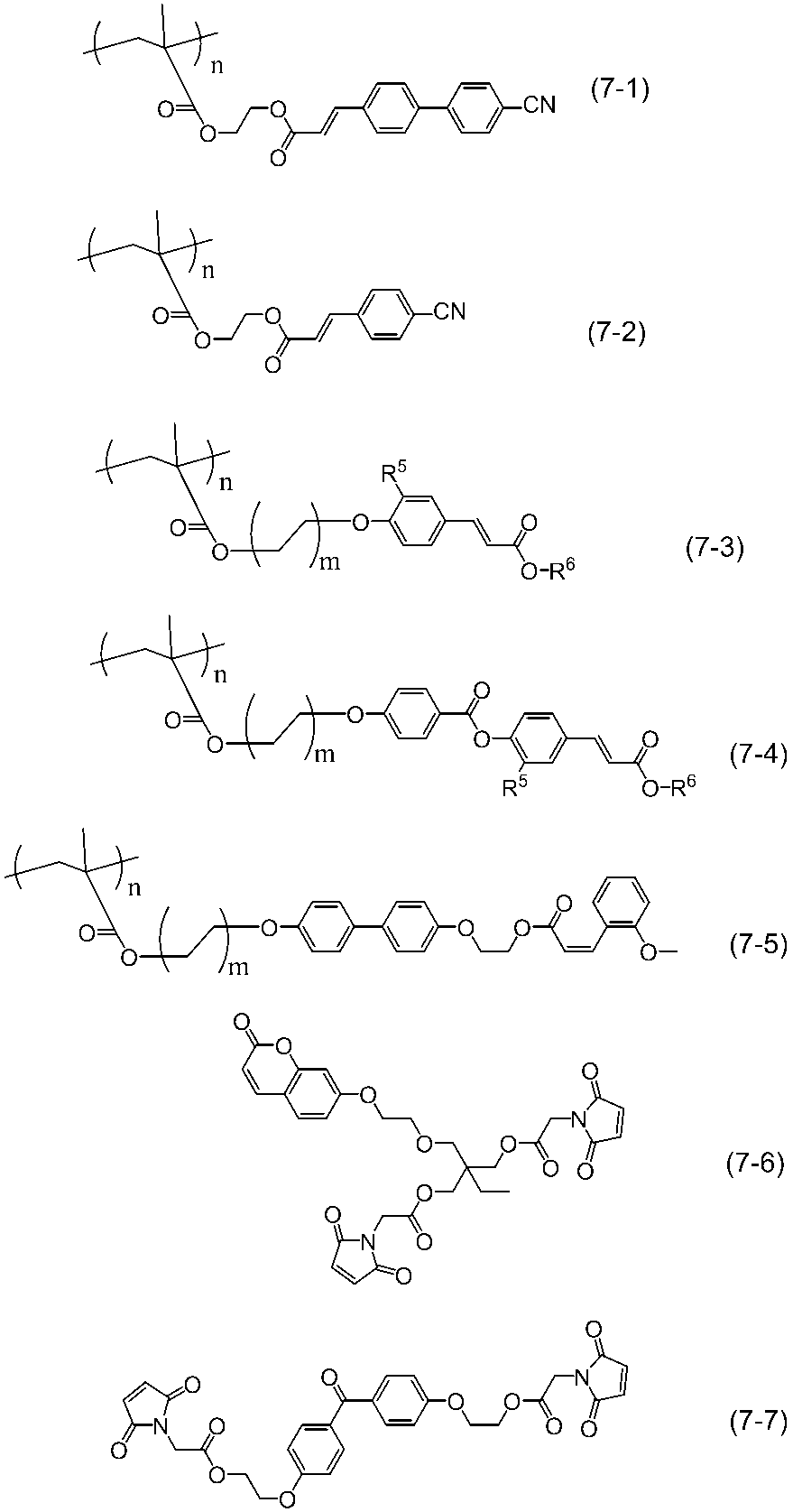

R7は、水素原子、ハロゲン原子、ハロゲン化アルキル基、アリルオキシ基、シアノ基、ニトロ基、アルキル基、ヒドロキシアルキル基、アルコキシ基、カルボキシ基若しくはそのアルカリ金属塩、アルコキシカルボニル基、ハロゲン化メトキシ基、ヒドロキシ基、スルホニルオキシ基若しくはそのアルカリ金属塩、アミノ基、カルバモイル基、スルファモイル基又は(メタ)アクリロイル基、(メタ)アクリロイルオキシ基、(メタ)アクリロイルアミノ基、ビニル基、ビニルオキシ基及びマレイミド基からなる群から選ばれる重合性官能基を表す。
本発明の液晶表示装置において、透明電極の材料としては、導電性の金属酸化物を用いることができ、金属酸化物としては酸化インジウム(In2O3)、酸化スズ(SnO2)、酸化亜鉛(ZnO)、酸化インジウムスズ(In2O3―SnO2)、酸化インジウム亜鉛(In2O3―ZnO)、ニオブ添加二酸化チタン(Ti1-xNbxO2)、フッ素ドープ酸化スズ、グラフェンナノリボン又は金属ナノワイヤー等が使用できるが、酸化亜鉛(ZnO)、酸化インジウムスズ(In2O3―SnO2)又は酸化インジウム亜鉛(In2O3―ZnO)が好ましい。これらの透明導電膜のパターニングには、フォト・エッチング法やマスクを用いる方法などを使用することができる。
バックライトの構成については特に制限はない。導光板方式及び直下型方式のいずれを用いてもよい。導光板方式のバックライト部は、光源及び導光板を備え、直下型方式
のバックライト部は、光源及び拡散板を備える。使用される光源についても特に制限はなく、電球、発光ダイオード(LED)、エレクトロルミネッセンスパネル(ELP)、1本又は複数の冷陰極管(CCFL)及び熱陰極蛍光灯(HCFL)等いずれも用いることができる。
また、バックライトには、光の利用効率を上げるために反射板、輝度向上膜等の部材を用いることができる。さらに、液晶表示装置の形成に際しては、上述の部材以外に例えば、拡散板、保護板、プリズムアレイ、レンズアレイシート、光拡散板等の部品を適宜1層又は2層以上配置することができる。
本発明の液晶表示装置は、偏光層を有していてもよい。偏光層は、自然光を直線偏光に変換する機能を有する部材である。前記偏光層は、偏光機能を有するフィルムであればよく、例えば、ポリビニルアルコール系フィルムにヨウ素や二色性色素を吸着させて延伸したフィルム、ポリビニルアルコール系フィルムを延伸してヨウ素や二色性染料あるいは、二色性色素を吸着させたフィルム、二色性染料を含有する水溶液を基板上に塗布して偏光層を形成したフィルム、ワイヤーグリッド偏光子等が挙げられる。
二色性色素としてヨウ素を用いる場合は、通常、ヨウ素及びヨウ化カリウムを含有する水溶液に、ポリビニルアルコール系樹脂フィルムを浸漬して染色する方法が採用される。二色性色素として二色性染料を用いる場合は、通常、水溶性二色性染料を含む水溶液に、ポリビニルアルコール系樹脂フィルムを浸漬して染色する方法が採用される。
また、偏光層にはさらに、必要に応じて、保護フィルムとなるフィルムを備えていてもよい。前記保護フィルムとしては、たとえばポリエチレン、ポリプロピレン、ノルボルネン系ポリマー等のポリオレフィンフィルム、ポリエチレンテレフタレートフィルム、ポリメタクリル酸エステルフィルム、ポリアクリル酸エステルフィルム、セルロースエステルフィルム、ポリエチレンナフタレートフィルム、ポリカーボネートフィルム、ポリスルフォンフィルム、ポリエーテルスルホンフィルム、ポリエーテルケトンフィルム、ポリフェニレンスルフィドフィルム及びポリフェニレンオキシドフィルム等が挙げられる。
前述した偏光層を有する光学部材には、液晶セルとの貼合のため粘着剤層を設けていてもよい。液晶セル以外の他部材と貼合するためにも粘着剤層を設けることもできる。粘着剤層を形成する粘着剤は特に制限されないが、例えばアクリル系重合体、シリコーン系ポリマー、ポリエステル、ポリウレタン、ポリアミド、ポリエーテル、フッ素系やゴム系などのポリマーをベースポリマーとするものを適宜に選択して用いることができる。特に、アクリル系粘着剤の如く光学的透明性に優れ、適度な濡れ性と凝集性と接着性の粘着特性を示して、耐候性や耐熱性などに優れるものが好ましく用いうる。また上記に加えて、吸湿による発泡現象や剥がれ現象の防止、熱膨張差等による光学特性の低下や液晶セルの反り防止、ひいては高品質で耐久性に優れる液晶表示装置の形成性などの点より、吸湿率が低くて耐熱性に優れる粘着層が好ましい。また、偏光板の固定と貼合の作業性(リワーク性)の観点から、粘着剤層の粘着力は1N/25mm以上が好ましく、5N/25mm以上がより好ましい。なお、上限は特に制限されない。粘着剤層は、例えば天然物や合成物の樹脂類、特に、粘着性付与樹脂や、ガラス繊維、ガラスビーズ、金属粉、その他の無機粉末等からなる充填剤や顔料、着色剤、酸化防止剤などの粘着層に添加されることの添加剤を含有していてもよい。また微粒子を含有して光拡散性を示す粘着剤層などであってもよい。粘着剤層は、異なる組成又は種類等のものの重畳層として偏光板や光学部材の片面又は両面に設けることもできる。また両面に設ける場合に、偏光板や光学部材の表裏において異なる組成や種類や厚さ等の粘着剤層とすることもできる。粘着剤層の厚さは、使用目的や接着力などに応じて適宜に決定でき、一般には1~500μmであり、5~200μmが好ましく、特に10~100μmが好ましい。
液晶表示装置は、ガラスなどの光透過性基板の間に液晶物質を封入した表示素子である。液晶表示装置は、図示しない表示制御装置からの電気的制御により液晶物質の分子配向を変化させることで、液晶セルの背面側に配置した偏光板により偏光されたバックライトの光の偏光状態を変化させ、液晶セルの視認側に配置した偏光板を透過する光量を制御することによって画像を表示させる。本実施形態の液晶表示装置は、負の誘電率異方性を有する棒状の液晶分子を配向させている。本発明の液晶セルは、一対の光透過性基板で挟まれた内側に位相差層を備えた、「インセル型位相差層」を有する点を特徴としている。
尚、本願において、一般式中に存在する環構造、連結基、置換基等は各一般式においてそれぞれ独立しているものとする。
実施例中、測定した特性は以下の通りである。
Δn :25℃における屈折率異方性
Δε :25℃における誘電率異方性
η :20℃における粘度(mPa・s)
γ1 :25℃における回転粘度(mPa・s)
dgap:セルの第一基板と第二基板のギャップ(μm)
VHR :70℃における電圧保持率(%)
(セル厚3.5μmのセルに液晶組成物を注入し、5V印加、フレームタイム200ms、パルス幅64μsの条件で測定した時の測定電圧と初期印加電圧との比を%で表した値)
ID :70℃におけるイオン密度(pC/cm2)
(セル厚3.5μmのセルに液晶組成物を注入し、MTR-1(株式会社東陽テクニカ製)で20V印加、周波数0.05Hzの条件で測定した時のイオン密度値)
焼き付き :
液晶表示素子の焼き付き評価は、表示エリア内に所定の固定パターンを1000時間表示させた後に、全画面均一な表示を行ったときの固定パターンの残像のレベルを目視にて以下の4段階評価で行った。
◎残像無し
○残像ごく僅かに有るも許容できるレベル
△残像有り許容できないレベル
×残像有りかなり劣悪
尚、実施例において化合物の記載について以下の略号を用いる。
-n -CnH2n+1 炭素数nの直鎖状のアルキル基
n- CnH2n+1- 炭素数nの直鎖状のアルキル基
-On -OCnH2n+1 炭素数nの直鎖状のアルコキシル基
nO- CnH2n+1O- 炭素数nの直鎖状のアルコキシル基
-V -CH=CH2
V- CH2=CH-
-V1 -CH=CH-CH3
1V- CH3-CH=CH-
-2V -CH2-CH2-CH=CH3
V2- CH3=CH-CH2-CH2-
-2V1 -CH2-CH2-CH=CH-CH3
1V2- CH3-CH=CH-CH2-CH2
(環構造)

位相差層に用いる本発明の重合性液晶組成物を以下のように調整した。
(重合性液晶組成物1の調整)
化合物(A1)を34部、化合物(A2)を10部、化合物(B1)を28部、化合物(B2)を28部、化合物(E1)を0.1部、化合物(I1)を0.2部、有機溶媒であるプロピレングリコールモノメチルエーテルアセテート(PGMEA)(D1)を300部、化合物(G1)を、攪拌プロペラを有する攪拌装置を用いて、攪拌速度が500rpm、溶液温度が60℃の条件下で1時間攪拌した。0.2μm(PTFE、膜厚:60μm)のメンブランフィルターを用い濾過圧力を0.20MPaになるよう調節して濾過し、本発明の重合性液晶組成物1を得た。
化合物(A1)を49部、化合物(A2)を11部、化合物(B1)を7部、化合物(B2)を12部、化合物(B3)を10部、化合物(C1)を11部、を0.1部、化合物(I1)0.2部、有機溶媒であるプロピレングリコールモノメチルエーテルアセテート(PGMEA)(D1)300部、化合物(G1)を、攪拌プロペラを有する攪拌装置を用いて、攪拌速度が500rpm、溶液温度が60℃の条件下で1時間攪拌した。0.2μm(PTFE、膜厚:60μm)のメンブランフィルターを用い濾過圧力を0.20MPaになるよう調節して濾過し、本発明の重合性液晶組成物2を得た。
重合性液晶組成物1、2の調製と同様に、表1~表4に示す化合物を調製し、本発明の重合性液晶組成物3~24、及び比較重合性液晶組成物1~20を得た。

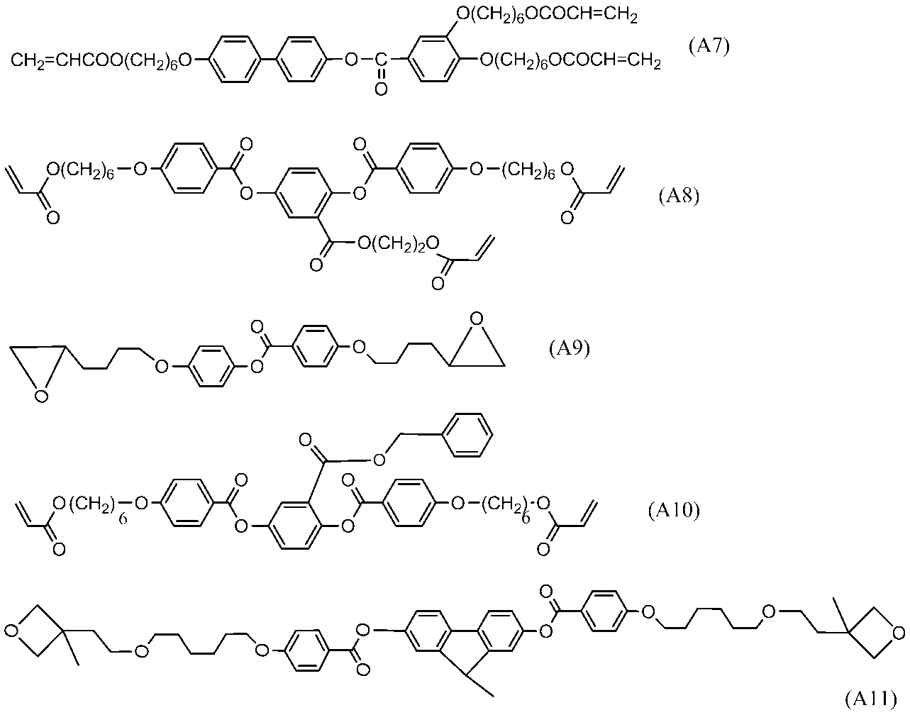

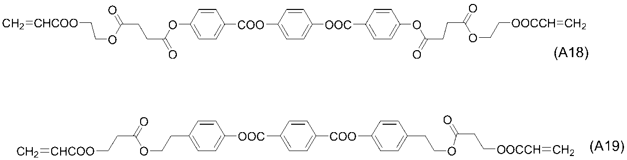
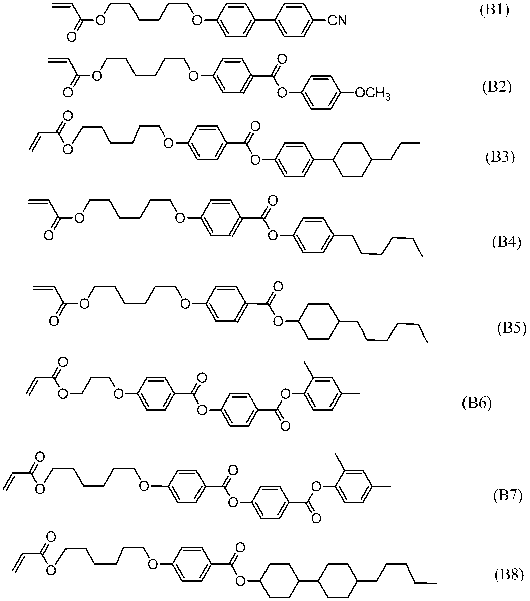
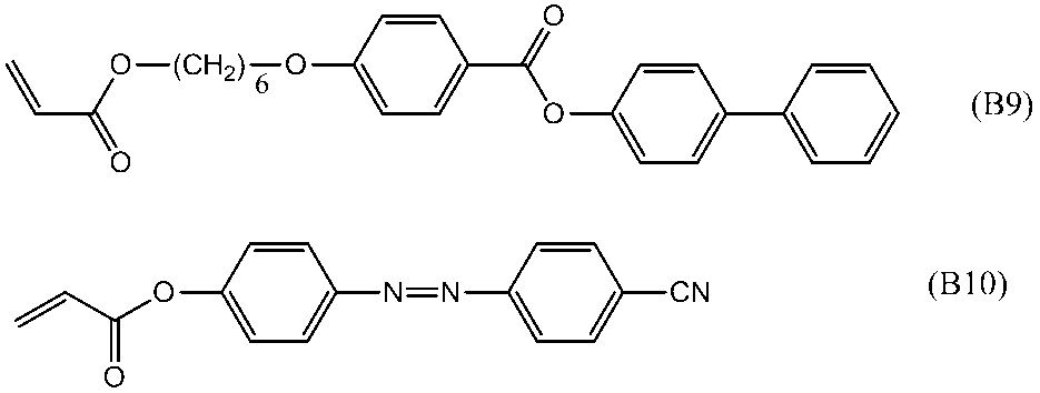

p-メトキシフェノール(E1)
イルガキュア907(G1)
イルガキュア651(G2)
イルガキュア127(G3)
DTS-102(G4)
イルガキュア251(G5)
ANTHRACURE UVS-1331(G6)
ポリプロピレン(重量平均分子量(MW):1275)(I1)
流動パラフィン(I2)
メガファックF-554(I3)
FTX-218(I4)


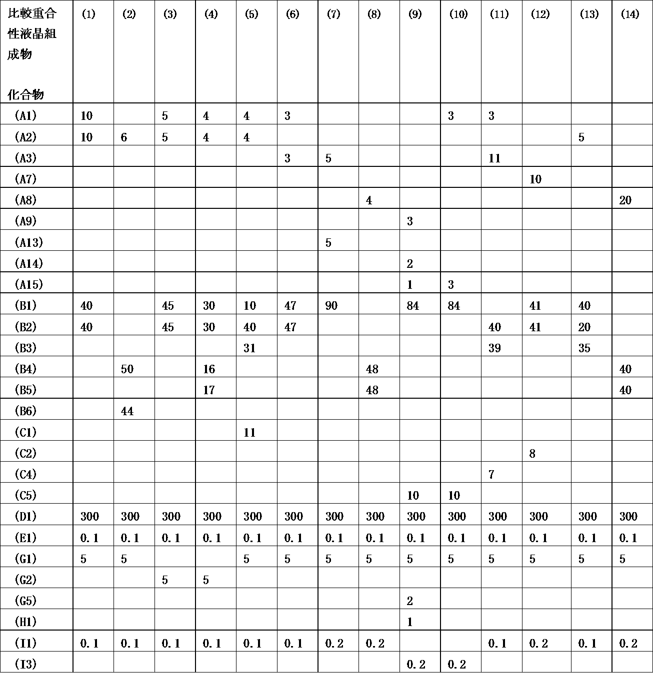
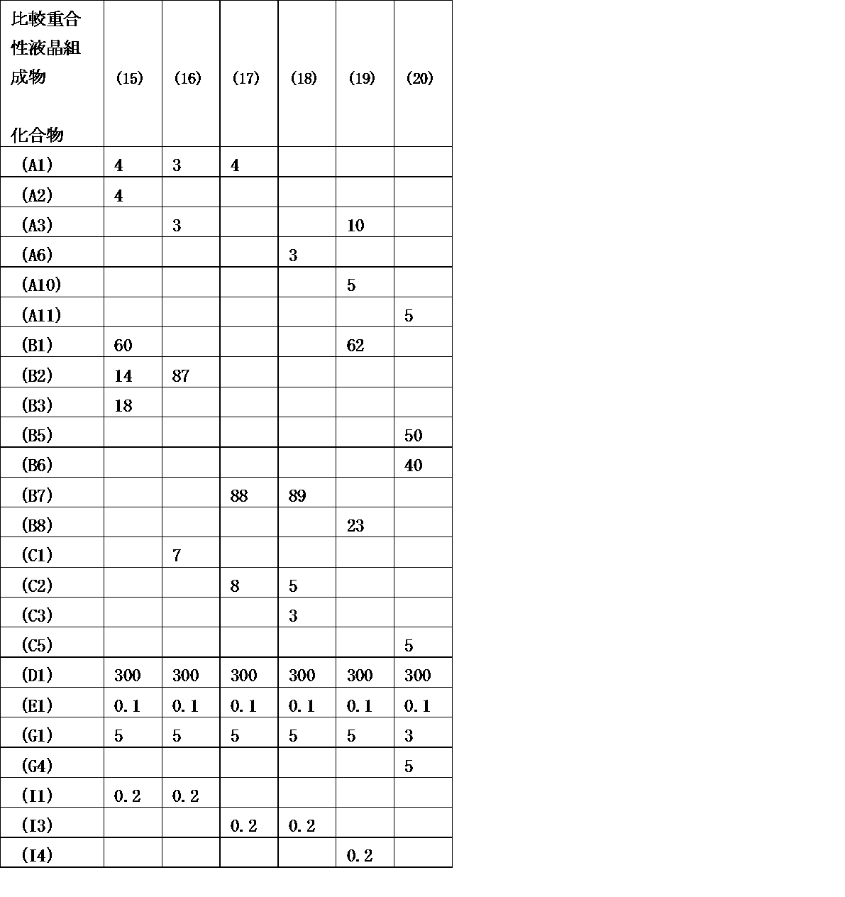
特開2013-33248の実施例1および実施例2に記載の方法と同様にして下記式(J)で表される化合物(単量体)を合成した。

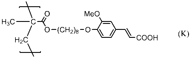
WO2012/053290の合成例1~5に記載の方法で位相差層用光配向剤組成物2を調整した。即ち、撹拌機、温度計、滴下漏斗及び還流冷却管を備えた反応容器に、2-(3,4-エポキシシクロヘキシル)エチルトリメトキシシラン (ECETS)100.0g、メチルイソブチルケトン500g及びトリエチルアミン10.0gを仕込み、室温で混合した。次いで、脱イオン水100gを滴下漏斗より30分かけて滴下した後、還流下で混合しつつ、80℃で6時間反応させた。反応終了後、有機層を取り出し、0.2質量%硝酸アンモニウム水溶液 により洗浄後の水が中性になるまで洗浄したのち、減圧下で溶媒及び水を留去することにより、エポキシ基を有するポリオルガノシロキサンを粘稠な透明液体として得た。得られたエポキシ基を有するポリオルガノシロキサンの重量平均分子量Mwは2,200であり、エポキシ当量は186g/モルであった。
WO2011/126021の合成例1に記載の方法で位相差層用光配向剤組成物3を調整した。即ち、4-(6-ヒドロキシヘキシルオキシ)ケイ皮酸メチルエステル0.46g、メトキシ化メチロールメラミンホルムアルデヒド樹脂(Mn:511)1.37g、ヘキサメトキシメチルメラミン0.55g、p-トルエンスルホン酸一水和物0.02gに対して、シクロヘキサノン17.5gを加え溶液を調整した。この溶液を孔径1μmのメンブランフィルターで濾過することにより、位相差層用光配向剤組成物3を得た。
第一の光透過性基板(3)に対して、カラーフィルタ層(4)を取り付けた後、水平配向膜(6)を形成し、弱ラビング処理を行った。ラビング済みの水平配向膜上(6)に、重合性液晶組成物1をスピンコーターで塗布し、80℃2分乾燥、室温冷却後、高圧水銀ランプで500mJ/cm2の紫外線光を照射し、ポジティブAプレートの第1の位相差層(7)を作成した。この位相差層上に重合性液晶組成物2をスピンコーターで塗布、80℃2分乾燥、室温冷却後、高圧水銀ランプで500mJ/cm2の紫外線光を照射し、ネガティブCプレートの第2の位相差層(8)を作成した。第1の位相差層(7)、第2の位相差層(8)に、透明電極層(9)を蒸着、配向膜(10)を形成した。第二の光透過性基板(14)に対して、画素電極層(13)を取り付けた後、配向膜(12)を形成後、弱ラビング処理を行った。配向膜層(10)、(12)の間の液晶層(11)に以下の液晶組成物1を注入し、実施例1のVAモードの液晶表示装置を作製した。実施例1の液晶表示装置を図11に示す。
得られた液晶表示装置のVHR及びIDを測定した。また、得られた液晶表示装置の焼き付き評価を行った。その結果を以下の表に示す。

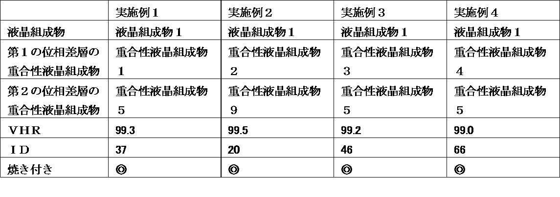
実施例1~4の液晶表示装置は、高いVHR及び小さいIDを実現できた。また、焼き付き評価においても残像の発生は認められなかった。
以下に示す液晶組成物及び重合性液晶組成物を用いた以外は実施例1と同様にして実施例5~12の液晶表示装置を作製し、そのVHR及びIDを測定した。また、その液晶表示装置の焼き付き評価を行った。その結果を以下の表に示す。


以下に示す液晶組成物及び重合性液晶組成物を用いた以外は実施例1と同様にして実施例13~24の液晶表示装置を作製し、そのVHR及びIDを測定した。また、その液晶表示装置の焼き付き評価を行った。その結果を以下の表に示す。


以下に示す液晶組成物及び重合性液晶組成物を用いた以外は実施例1と同様にして実施例25~36の液晶表示装置を作製し、そのVHR及びIDを測定した。また、その液晶表示装置の焼き付き評価を行った。その結果を以下の表に示す。
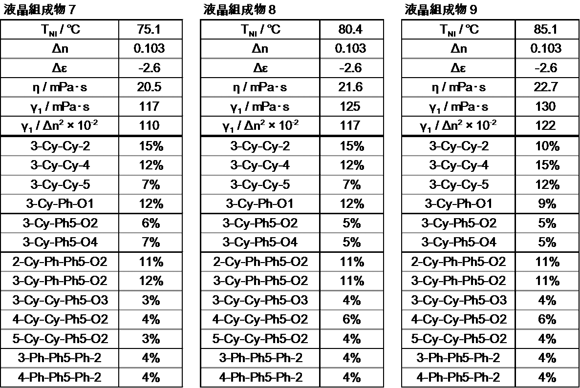
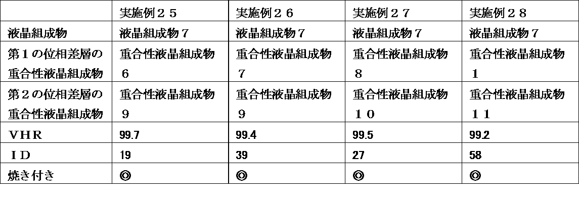


以下に示す液晶組成物及び重合性液晶組成物を用いた以外は実施例1と同様にして実施例37~48の液晶表示装置を作製し、そのVHR及びIDを測定した。また、その液晶表示装置の焼き付き評価を行った。その結果を以下の表に示す。

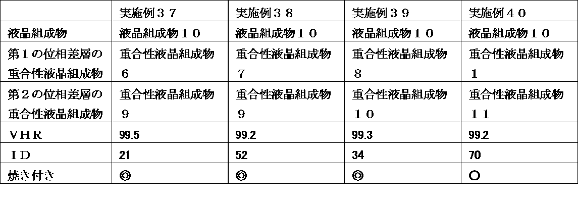

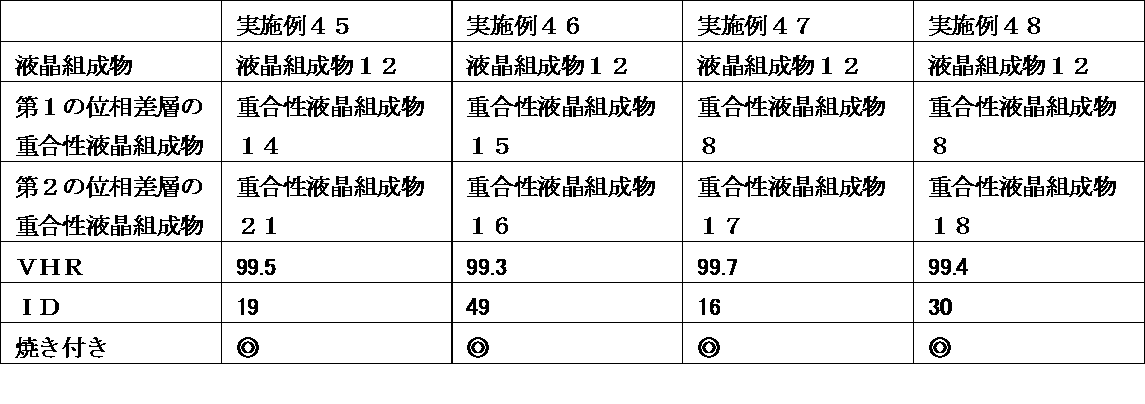
以下に示す液晶組成物及び重合性液晶組成物を用いた以外は実施例1と同様にして実施例2~4の液晶表示装置を作製し、そのVHR及びIDを測定した。また、その液晶表示装置の焼き付き評価を行った。その結果を以下の表に示す。


以下の表に示す液晶組成物及び重合性液晶組成物を用いた以外は実施例1と同様にして実施例61~72の液晶表示装置を作製し、そのVHR及びIDを測定した。また、その液晶表示装置の焼き付き評価を行った。その結果を以下の表に示す。


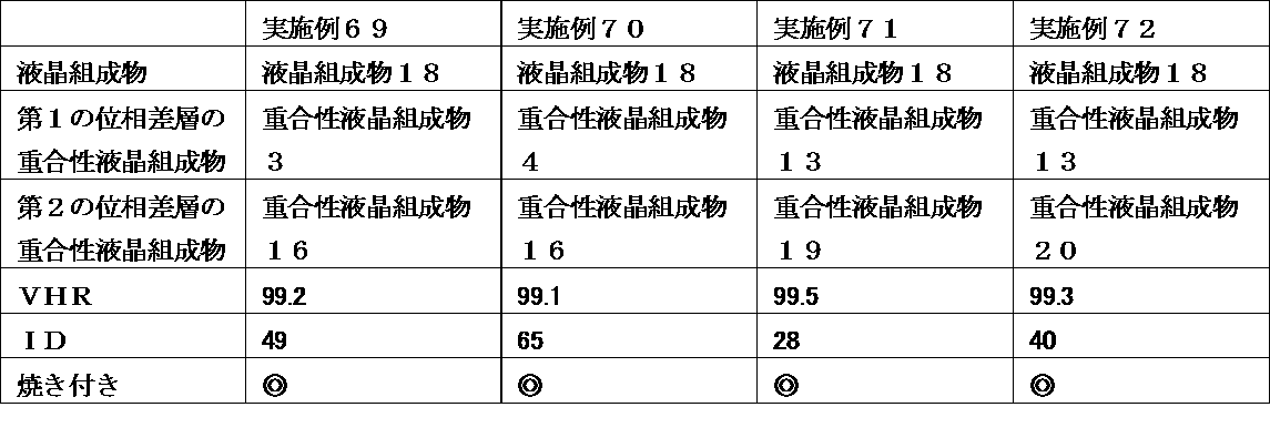
以下の表に示す液晶組成物及び重合性液晶組成物を用いた以外は実施例1と同様にして実施例73~84の液晶表示装置を作製し、そのVHR及びIDを測定した。また、その液晶表示装置の焼き付き評価を行った。その結果を以下の表に示す。


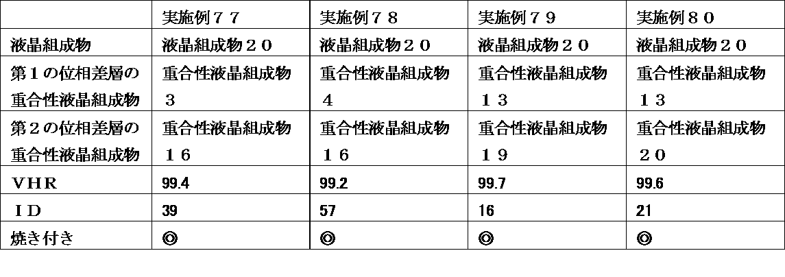

以下の表に示す液晶組成物及び重合性液晶組成物を用いた以外は実施例1と同様にして実施例85~96の液晶表示装置を作製し、そのVHR及びIDを測定した。また、その液晶表示装置の焼き付き評価を行った。その結果を以下の表に示す。
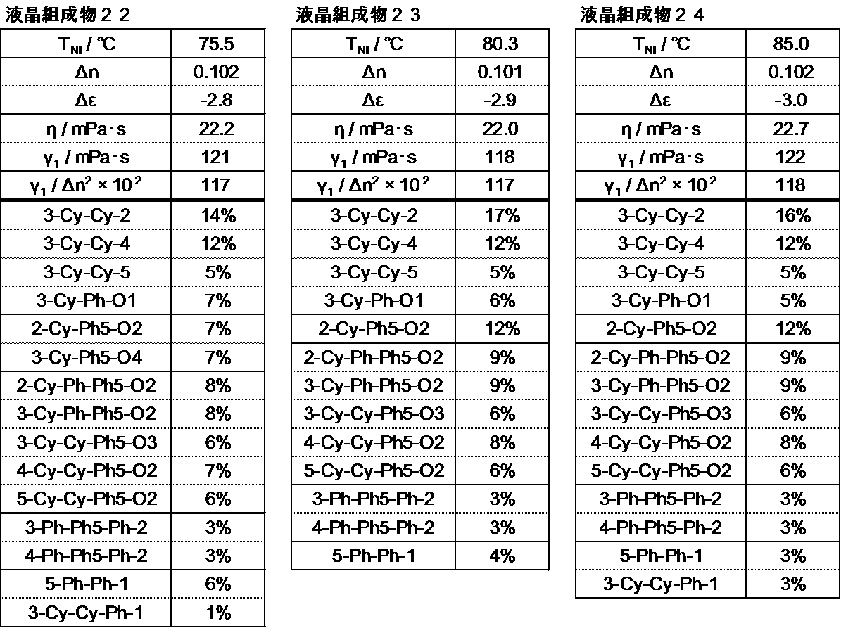


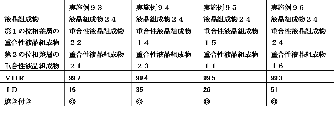
以下の表に示す液晶組成物及び重合性液晶組成物を用いた以外は実施例1と同様にして実施例97~108の液晶表示装置を作製し、そのVHR及びIDを測定した。また、その液晶表示装置の焼き付き評価を行った。その結果を以下の表に示す。


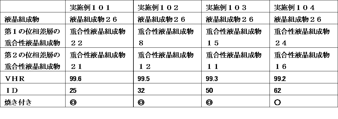

液晶組成物1に2-メチル-アクリル酸4-{2-[4-(2-アクリロイルオキシ-エチル)-フェノキシカルボニル]-エチル}-ビフェニル-4’-イルエステル0.3質量%を混合し液晶組成物28とした。実施例1と同様にこの液晶組成物28を注入し、電極間に駆動電圧を印加したまま、紫外線を600秒間照射(3.0J/cm2)し、重合処理を行い、実施例109~112の液晶表示装置を作成し、そのVHR及びIDを測定した。また、その液晶表示装置の焼き付き評価を行った。その結果を以下の表に示す。

液晶組成物13にビスメタクリル酸ビフェニル‐4,4’‐ジイル 0.3質量%を混合し液晶組成物29とした。実施例1と同様にこの液晶組成物29を注入し、電極間に駆動電圧を印加したまま、紫外線を600秒間照射(3.0J/cm2)し、重合処理を行い実施例113~116の液晶表示装置を作成し、そのVHR及びIDを測定した。また、その液晶表示装置の焼き付き評価を行った。その結果を以下の表に示す。

液晶組成物19にビスメタクリル酸 3‐フルオロビフェニル‐4,4’‐ジイル 0.3質量%を混合し液晶組成物30とした。実施例1と同様にこの液晶組成物30を注入し、電極間に駆動電圧を印加したまま、紫外線を600秒間照射(3.0J/cm2)し、重合処理を行い、実施例117~120の液晶表示装置を作成し、そのVHR及びIDを測定した。また、その液晶表示装置の焼き付き評価を行った。その結果を以下の表に示す。

以下の表に示す液晶組成物及び重合性液晶組成物を用いた以外は実施例1と同様にして実施例121~132の液晶表示装置を作製し、そのVHR及びIDを測定した。また、その液晶表示装置の焼き付き評価を行った。その結果を以下の表に示す。
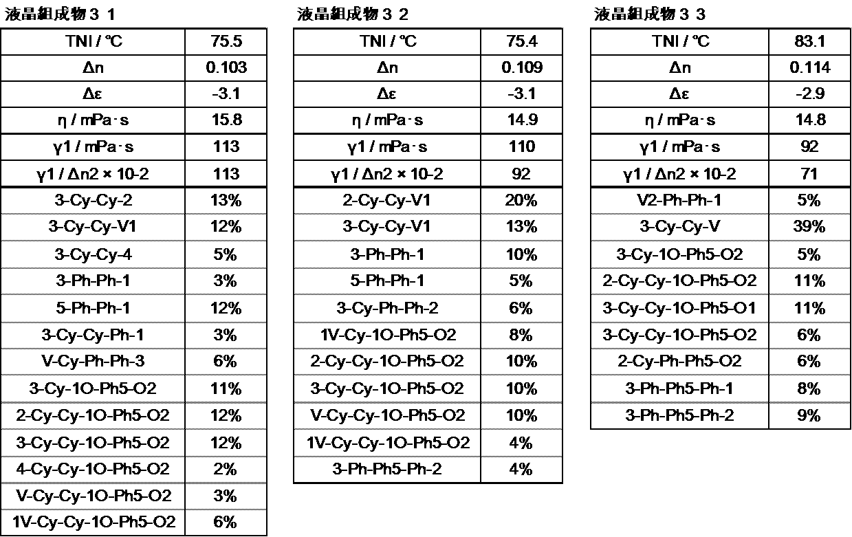


以下の表に示す液晶組成物及び重合性液晶組成物を用いた以外は実施例1と同様にして実施例133~140の液晶表示装置を作製し、そのVHR及びIDを測定した。また、その液晶表示装置の焼き付き評価を行った。その結果を以下の表に示す。


以下の表に示す液晶組成物及び重合性液晶組成物を用い、位相差層用のラビングした配向膜(6)の替わりに、光配向材料を用いた光配向膜(6)を使用した以外は、実施例1と同様にして実施例141~149の液晶表示装置を作製し、そのVHR及びIDを測定した。また、その液晶表示装置の焼き付き評価を行った。その結果を以下の表に示す。
尚、光配向膜は以下の方法で作成した。光透過性基板上にスピンコーターを用いて位相差層用光配向剤組成物を塗布した後、温度80℃で120秒間ホットプレート上においてプリベークを行い、膜厚0.1μmの塗膜を形成した。この膜をオーブン中、温度200℃で1時間ポストベークを行い、硬化膜を形成した。位相差層用光配向剤組成物1、2の場合には、硬化膜に313nmの直線偏光を300J/m2照射した。位相差層用光配向剤組成物3の場合には、硬化膜に300nmの直線偏光を300J/m2照射した。


以下の表に示す液晶組成物及び重合性液晶組成物を用いた以外は実施例1と同様にして比較例1~4の液晶表示装置を作製し、そのVHR及びIDを測定した。また、その液晶表示装置の焼き付き評価を行った。その結果を以下の表に示す。


以下の表に示す液晶組成物及び重合性液晶組成物を用いた以外は実施例1と同様にして比較例13~24の液晶表示装置を作製し、そのVHR及びIDを測定した。また、その液晶表示装置の焼き付き評価を行った。その結果を以下の表に示す。


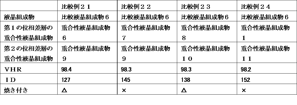
以下の表に示す液晶組成物及び重合性液晶組成物を用いた以外は実施例1と同様にして比較例25~36の液晶表示装置を作製し、そのVHR及びIDを測定した。また、その液晶表示装置の焼き付き評価を行った。その結果を以下の表に示す。
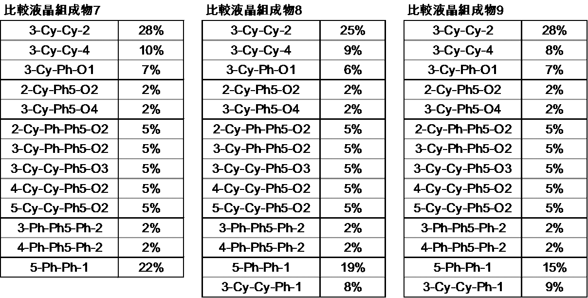


以下の表に示す液晶組成物及び重合性液晶組成物を用いた以外は実施例1と同様にして比較例37~44の液晶表示装置を作製し、そのVHR及びIDを測定した。また、その液晶表示装置の焼き付き評価を行った。その結果を以下の表に示す。

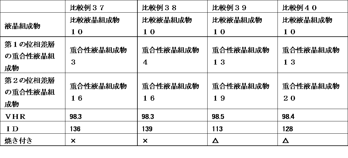

以下の表に示す液晶組成物及び重合性液晶組成物を用いた以外は実施例1と同様にして比較例45~56の液晶表示装置を作製し、そのVHR及びIDを測定した。また、その液晶表示装置の焼き付き評価を行った。その結果を以下の表に示す。


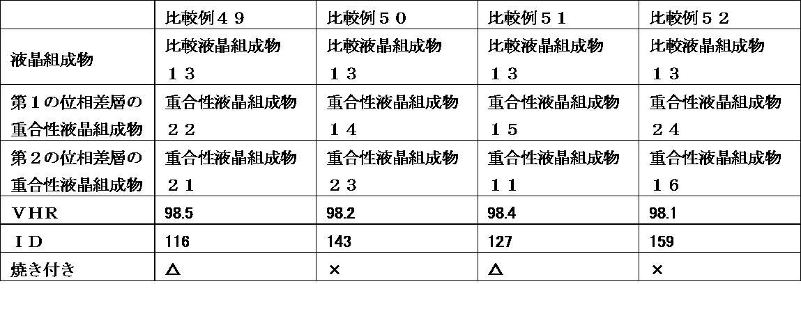
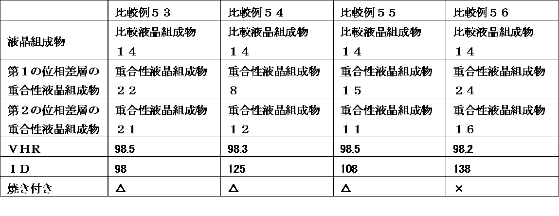
以下の表に示す液晶組成物及び重合性液晶組成物を用いた以外は実施例1と同様にして比較例57~60の液晶表示装置を作製し、そのVHR及びIDを測定した。また、その液晶表示装置の焼き付き評価を行った。その結果を以下の表に示す。
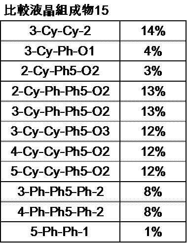
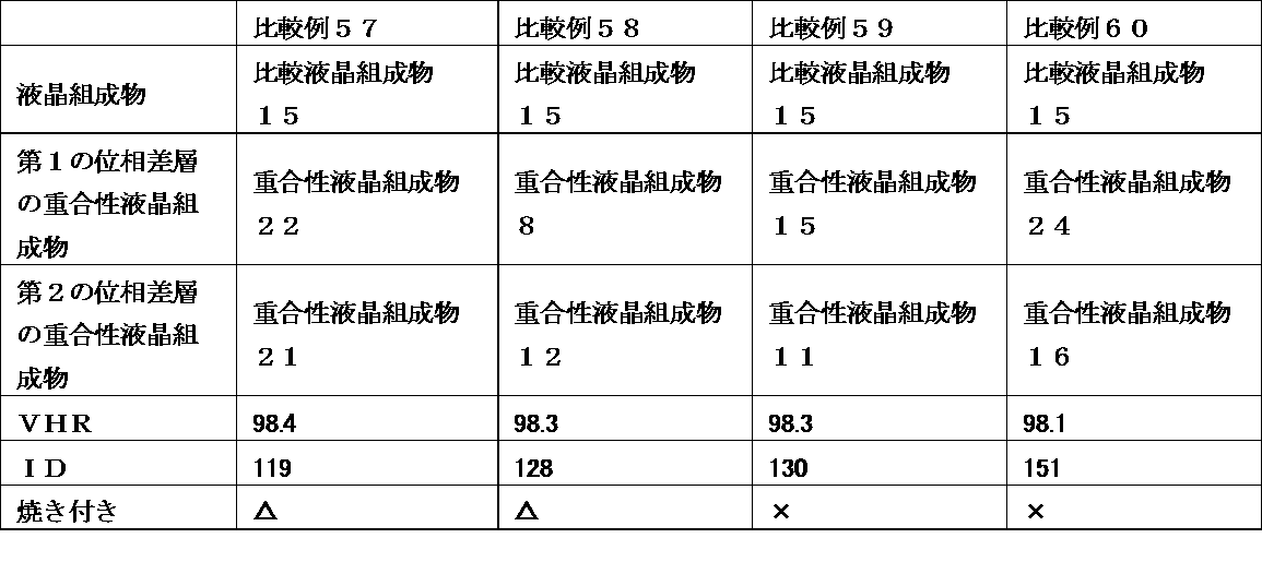
以下の表に示す液晶組成物及び重合性液晶組成物を用いた以外は実施例1と同様にして比較例61~92の液晶表示装置を作製し、そのVHR及びIDを測定した。また、その液晶表示装置の焼き付き評価を行った。その結果を以下の表に示す。

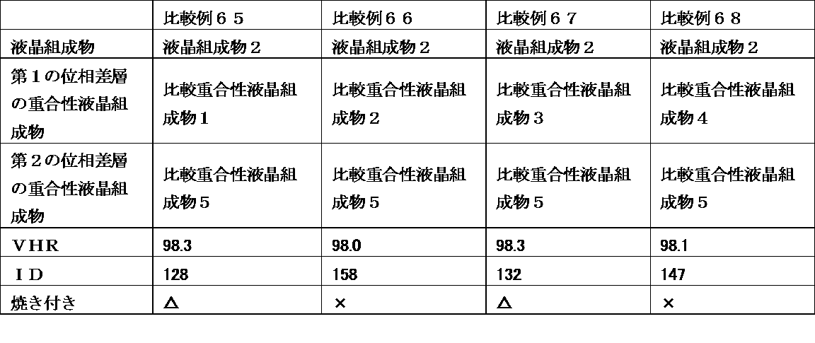


Claims (15)
- 第一の基板と、第二の基板と、前記第一の基板と第二の基板間に挟持された液晶層、及び前記一対の基板間に位相差層を有し、少なくとも一対の電極を備えた液晶表示装置であって、前記液晶層が一般式(I)

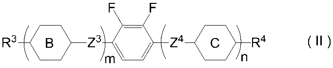
前記位相差フィルム層が、2つ以上の重合性官能基を有する液晶化合物を25重量%以上含有する重合性液晶組成物を重合させることにより得られる光学異方体である液晶表示装置。 - 前記2つ以上の重合性官能基を有する液晶化合物として、一般式(1)で表される化合物を含有する請求1記載の液晶表示装置。
(式中、P1は重合性官能基を表し、Sp1は炭素原子数0~18のアルキレン基を表し(該アルキレン基は1つ以上のハロゲン原子、CN又は重合性官能基を有する炭素原子数1~8のアルキル基により置換されていても良く、この基中に存在する1つのCH2基又は隣接していない2つ以上のCH2基はそれぞれ相互に独立して、酸素原子が相互に直接結合しない形で、-O-、-S-、-NH-、-N(CH3)-、-CO-、-COO-、-OCO-、-OCOO-、-SCO-、-COS-又は-C≡C-により置き換えられていても良い。)、m1は0又は1を表し、MGはメソゲン基又はメソゲン性支持基を表し、R1は、水素原子、ハロゲン原子、シアノ基又は炭素原子数1~18のアルキル基を表すが、該アルキル基は1つ以上のハロゲン原子又はCNにより置換されていても良く、この基中に存在する1つのCH2基又は隣接していない2つ以上のCH2基はそれぞれ相互に独立して、酸素原子が相互に直接結合しない形で、-O-、-S-、-NH-、-N(CH3)-、-CO-、-COO-、-OCO-、-OCOO-、-SCO-、-COS-又は-C≡C-により置き換えられていても良く、あるいはR1は一般式(1-a)

MGで表されるメソゲン基又はメソゲン性支持基は、一般式(1-b)


- 前記位相差層が、2つの重合性官能基を有する液晶化合物を含有する重合性液晶組成物を重合させることにより得られる光学異方体である請求項1又は2記載の液晶表示装置。
- 前記2つの重合性官能基を有する液晶化合物として、以下の一般式(2)で表される化合物を含有する請求項3記載の液晶表示装置。

n、l及びkはそれぞれ独立して0又は1を表し、0≦n+l+k≦3を表し、
A1、A2、A3、A4、及びA5は、それぞれ独立して、1,4-フェニレン基、1,4-シクロヘキシレン基、1,4-シクロヘキセニル基、テトラヒドロピラン-2,5-ジイル基、1,3-ジオキサン-2,5-ジイル基、テトラヒドロチオピラン-2,5-ジイル基、1,4-ビシクロ(2,2,2)オクチレン基、デカヒドロナフタレン-2,6-ジイル基、ピリジン-2,5-ジイル基、ピリミジン-2,5-ジイル基、ピラジン-2,5-ジイル基、チオフェン-2,5-ジイル基-、1,2,3,4-テトラヒドロナフタレン-2,6-ジイル基、2,6-ナフチレン基、フェナントレン-2,7-ジイル基、9,10-ジヒドロフェナントレン-2,7-ジイル基、1,2,3,4,4a,9,10a-オクタヒドロフェナントレン-2,7-ジイル基、1,4-ナフチレン基、ベンゾ[1,2-b:4,5-b‘]ジチオフェン-2,6-ジイル基、ベンゾ[1,2-b:4,5-b‘]ジセレノフェン-2,6-ジイル基、[1]ベンゾチエノ[3,2-b]チオフェン-2,7-ジイル基、[1]ベンゾセレノフェノ[3,2-b]セレノフェン-2,7-ジイル基、又はフルオレン-2,7-ジイル基を表し、
置換基として1個以上のF、Cl、CF3、OCF3、CN基、炭素原子数1~8のアルキル基、アルコキシ基、アルカノイル基、アルカノイルオキシ基、炭素原子数2~8のアルケニル基、アルケニルオキシ基、アルケノイル基、アルケノイルオキシ基を表し、
Z0、Z1、Z2、Z3、Z4、及びZ5はそれぞれ独立して、-COO-、-OCO-、-CH2 CH2-、-OCH2-、-CH2O-、-CH=CH-、-C≡C-、-CH=CHCOO-、-OCOCH=CH-、-CH2CH2COO-、-CH2CH2OCO-、-COOCH2CH2-、-OCOCH2CH2-、-CONH-、-NHCO-、炭素数2~10のハロゲン原子を有してもよいアルキル基又は単結合を表し、
n2b、k2b、l2bはそれぞれ独立して、0又は1、かつ、0≦n+l+k≦3を表す。) - 前記位相差層が、更に1つの重合性官能基を有する液晶化合物を含有する重合性液晶組成物を重合させることにより得られる光学異方体である請求項1~4のいずれか1項に記載の液晶表示装置。
- 前記1つの重合性官能基を有する液晶化合物が前記重合性液晶組成物中に5~75重量%含有する請求項5に記載の液晶表示装置。
- 前記1つの重合性官能基を有する液晶化合物として、以下の一般式(4)で表される化合物を含有する請求項5又は6記載の液晶表示装置。

R4は、水素原子、ハロゲン原子、シアノ基又は炭素原子数1~18のアルキル基を表すが、該アルキル基は1つ以上のハロゲン原子又はCNにより置換されていても良く、この基中に存在する1つのCH2基又は隣接していない2つ以上のCH2基はそれぞれ相互に独立して、酸素原子が相互に直接結合しない形で、-O-、-S-、-NH-、-N(CH3)-、-CO-、-COO-、-OCO-、-OCOO-、-SCO-、-COS-又は-C≡C-により置き換えられていても良い。) - 前記位相差層が、ポジティブAプレート及び/又はネガティブCプレートから構成される請求項1~7のいずれか1項に記載の液晶表示装置。
- インセル型位相差層に使用される、前記請求項1~8のいずれか1項に記載の重合性液晶組成物。
- 前記液晶組成物層に、更に一般式(III)

- 一般式(I)におけるAがトランス-1,4-シクロヘキシレン基を表す化合物、及びAが1,4-フェニレン基を表す化合物をそれぞれ少なくとも1種以上含有する請求項1~10のいずれか1項に記載の液晶表示装置。
- 前記液晶組成物層に一般式(II-1)及び/又は一般式(II-2)で表される化合物を含有する請求項1~11のいずれか1項に記載の液晶表示装置。
(式中、R3及びR4はそれぞれ独立して炭素原子数1~8のアルキル基、炭素原子数2~8のアルケニル基、炭素原子数1~8のアルコキシ基又は炭素原子数2~8のアルケニルオキシ基を表し、Z5及びZ6はそれぞれ独立して単結合、-CH=CH-、-C≡C-、-CH2CH2-、-(CH2)4-、-COO-、-OCO-、-OCH2-、-CH2O-、-OCF2-又は-CF2O-を表し、m1、m2及びn2はそれぞれ独立して0又は1を表す。)
- 前記液晶組成物層を構成する液晶組成物の、以下の式で表されるZ

- 前記液晶組成物層を構成する液晶組成物の、ネマチック液晶相上限温度が60~120℃であり、ネマチック液晶相下限温度が‐20℃以下であり、ネマチック液晶相上限温度と下限温度の差が100~150である請求項1~13の何れか1項に記載の液晶表示装置。
- 前記液晶組成物層を構成する液晶組成物の比抵抗が1012(Ω・m)以上である請求項1~14の何れか1項に記載の液晶表示装置。
Priority Applications (5)
| Application Number | Priority Date | Filing Date | Title |
|---|---|---|---|
| KR1020167022730A KR101724348B1 (ko) | 2014-02-27 | 2015-02-24 | 액정 표시 장치 |
| JP2015551895A JP5888477B2 (ja) | 2014-02-27 | 2015-02-24 | 液晶表示装置 |
| CN201580007119.4A CN105960608B (zh) | 2014-02-27 | 2015-02-24 | 液晶显示装置 |
| US15/120,876 US20160370626A1 (en) | 2014-02-27 | 2015-02-24 | Liquid crystal display device |
| EP15754621.9A EP3112930B1 (en) | 2014-02-27 | 2015-02-24 | Liquid crystal display device |
Applications Claiming Priority (2)
| Application Number | Priority Date | Filing Date | Title |
|---|---|---|---|
| JP2014036682 | 2014-02-27 | ||
| JP2014-036682 | 2014-02-27 |
Publications (1)
| Publication Number | Publication Date |
|---|---|
| WO2015129672A1 true WO2015129672A1 (ja) | 2015-09-03 |
Family
ID=54008990
Family Applications (1)
| Application Number | Title | Priority Date | Filing Date |
|---|---|---|---|
| PCT/JP2015/055172 WO2015129672A1 (ja) | 2014-02-27 | 2015-02-24 | 液晶表示装置 |
Country Status (7)
| Country | Link |
|---|---|
| US (1) | US20160370626A1 (ja) |
| EP (1) | EP3112930B1 (ja) |
| JP (1) | JP5888477B2 (ja) |
| KR (1) | KR101724348B1 (ja) |
| CN (1) | CN105960608B (ja) |
| TW (1) | TWI642766B (ja) |
| WO (1) | WO2015129672A1 (ja) |
Cited By (7)
| Publication number | Priority date | Publication date | Assignee | Title |
|---|---|---|---|---|
| CN106611774A (zh) * | 2015-10-26 | 2017-05-03 | 三星显示有限公司 | 柔性显示装置 |
| US20180275329A1 (en) * | 2015-09-30 | 2018-09-27 | Zeon Corporation | Optical film and method for producing same |
| JP2019144461A (ja) * | 2018-02-22 | 2019-08-29 | Jnc株式会社 | インセル位相差膜 |
| JPWO2018151070A1 (ja) * | 2017-02-20 | 2019-11-07 | Dic株式会社 | 光学異方体 |
| US11697666B2 (en) | 2021-04-16 | 2023-07-11 | Gilead Sciences, Inc. | Methods of preparing carbanucleosides using amides |
| US11767337B2 (en) | 2020-02-18 | 2023-09-26 | Gilead Sciences, Inc. | Antiviral compounds |
| JP7468071B2 (ja) | 2020-03-31 | 2024-04-16 | 大日本印刷株式会社 | 重合性化合物、重合性液晶組成物、重合体、位相差フィルム及びその製造方法、転写用積層体、光学部材及びその製造方法、並びに表示装置 |
Families Citing this family (7)
| Publication number | Priority date | Publication date | Assignee | Title |
|---|---|---|---|---|
| WO2016148041A1 (ja) * | 2015-03-18 | 2016-09-22 | シャープ株式会社 | 液晶表示装置 |
| KR102167466B1 (ko) * | 2016-03-29 | 2020-10-19 | 스미또모 가가꾸 가부시끼가이샤 | 액정 조성물 |
| CN109072080A (zh) * | 2016-06-10 | 2018-12-21 | Dic株式会社 | 组合物及液晶显示元件 |
| CN108219801B (zh) * | 2016-12-15 | 2021-05-25 | 江苏和成显示科技有限公司 | 具有负介电各向异性的液晶组合物及其应用 |
| WO2018147028A1 (ja) * | 2017-02-13 | 2018-08-16 | コニカミノルタ株式会社 | 液晶表示装置およびこの液晶表示装置に用いられる一対の光学フィルム |
| JP7114868B2 (ja) * | 2017-09-26 | 2022-08-09 | Dic株式会社 | 液晶表示装置 |
| CN110908030A (zh) * | 2019-11-08 | 2020-03-24 | 浙江怡诚光电科技有限公司 | 圆偏光板及其制备方法,显示器 |
Citations (3)
| Publication number | Priority date | Publication date | Assignee | Title |
|---|---|---|---|---|
| JP2000221506A (ja) * | 1999-02-01 | 2000-08-11 | Sharp Corp | 液晶表示装置 |
| WO2007094450A1 (ja) * | 2006-02-17 | 2007-08-23 | Dic Corporation | 重合性液晶組成物 |
| JP5299588B1 (ja) * | 2012-09-20 | 2013-09-25 | Dic株式会社 | 液晶表示装置 |
Family Cites Families (6)
| Publication number | Priority date | Publication date | Assignee | Title |
|---|---|---|---|---|
| DE602004015756D1 (de) * | 2003-04-08 | 2008-09-25 | Merck Patent Gmbh | Optischer film in einer flüssigkristallanzeige |
| JP2007262288A (ja) * | 2006-03-29 | 2007-10-11 | Dainippon Ink & Chem Inc | 重合性液晶組成物 |
| US8730435B2 (en) | 2009-07-17 | 2014-05-20 | Jnc Corporation | Liquid crystal display device having retardation film formed of liquid crystalline polyimide having photoreactive group |
| CN103154811B (zh) * | 2010-09-28 | 2015-07-15 | Dic株式会社 | 新型液晶显示装置及有用的液晶组合物 |
| JP2012078431A (ja) | 2010-09-30 | 2012-04-19 | Sumitomo Chemical Co Ltd | 液晶パネル及びこれを備えた液晶表示装置 |
| CN103858049B (zh) * | 2012-10-03 | 2016-05-11 | Dic株式会社 | 液晶显示装置 |
-
2015
- 2015-02-24 WO PCT/JP2015/055172 patent/WO2015129672A1/ja active Application Filing
- 2015-02-24 US US15/120,876 patent/US20160370626A1/en not_active Abandoned
- 2015-02-24 JP JP2015551895A patent/JP5888477B2/ja active Active
- 2015-02-24 KR KR1020167022730A patent/KR101724348B1/ko active IP Right Grant
- 2015-02-24 CN CN201580007119.4A patent/CN105960608B/zh active Active
- 2015-02-24 EP EP15754621.9A patent/EP3112930B1/en active Active
- 2015-02-25 TW TW104106020A patent/TWI642766B/zh active
Patent Citations (3)
| Publication number | Priority date | Publication date | Assignee | Title |
|---|---|---|---|---|
| JP2000221506A (ja) * | 1999-02-01 | 2000-08-11 | Sharp Corp | 液晶表示装置 |
| WO2007094450A1 (ja) * | 2006-02-17 | 2007-08-23 | Dic Corporation | 重合性液晶組成物 |
| JP5299588B1 (ja) * | 2012-09-20 | 2013-09-25 | Dic株式会社 | 液晶表示装置 |
Cited By (7)
| Publication number | Priority date | Publication date | Assignee | Title |
|---|---|---|---|---|
| US20180275329A1 (en) * | 2015-09-30 | 2018-09-27 | Zeon Corporation | Optical film and method for producing same |
| CN106611774A (zh) * | 2015-10-26 | 2017-05-03 | 三星显示有限公司 | 柔性显示装置 |
| JPWO2018151070A1 (ja) * | 2017-02-20 | 2019-11-07 | Dic株式会社 | 光学異方体 |
| JP2019144461A (ja) * | 2018-02-22 | 2019-08-29 | Jnc株式会社 | インセル位相差膜 |
| US11767337B2 (en) | 2020-02-18 | 2023-09-26 | Gilead Sciences, Inc. | Antiviral compounds |
| JP7468071B2 (ja) | 2020-03-31 | 2024-04-16 | 大日本印刷株式会社 | 重合性化合物、重合性液晶組成物、重合体、位相差フィルム及びその製造方法、転写用積層体、光学部材及びその製造方法、並びに表示装置 |
| US11697666B2 (en) | 2021-04-16 | 2023-07-11 | Gilead Sciences, Inc. | Methods of preparing carbanucleosides using amides |
Also Published As
| Publication number | Publication date |
|---|---|
| JP5888477B2 (ja) | 2016-03-22 |
| TW201546248A (zh) | 2015-12-16 |
| EP3112930A1 (en) | 2017-01-04 |
| EP3112930B1 (en) | 2019-03-27 |
| TWI642766B (zh) | 2018-12-01 |
| KR101724348B1 (ko) | 2017-04-07 |
| KR20160105908A (ko) | 2016-09-07 |
| CN105960608B (zh) | 2018-06-15 |
| JPWO2015129672A1 (ja) | 2017-03-30 |
| EP3112930A4 (en) | 2017-10-18 |
| US20160370626A1 (en) | 2016-12-22 |
| CN105960608A (zh) | 2016-09-21 |
Similar Documents
| Publication | Publication Date | Title |
|---|---|---|
| JP5888477B2 (ja) | 液晶表示装置 | |
| JP5888480B1 (ja) | 液晶表示装置 | |
| JP2016166344A (ja) | 重合性液晶組成物及び光学異方性フィルム | |
| WO2015186562A1 (ja) | 液晶配向膜 | |
| KR102197550B1 (ko) | 중합성 액정 조성물 및 그것을 이용한 광학 필름 | |
| JP5413705B1 (ja) | 液晶表示装置 | |
| JP5915823B2 (ja) | メソゲン基を有する化合物を含有する重合性組成物及びその重合体 | |
| WO2015133331A1 (ja) | メソゲン基を有する化合物を含有する混合物 | |
| JP5299588B1 (ja) | 液晶表示装置 | |
| WO2018225579A1 (ja) | 重合性液晶組成物、それを用いた光学フィルム、及びその製造方法 | |
| JP6264513B2 (ja) | 重合性液晶組成物及びそれを用いた光学異方体 | |
| JP6343914B2 (ja) | 化合物、重合体、液晶配向膜、液晶表示素子、及び光学異方体 | |
| WO2018151070A1 (ja) | 光学異方体 | |
| JP2019206677A (ja) | 重合性液晶化合物、組成物およびその重合体 | |
| JP2019215404A (ja) | 重合性液晶組成物、その液晶重合膜、位相差フィルム、偏光板および表示素子 |
Legal Events
| Date | Code | Title | Description |
|---|---|---|---|
| 121 | Ep: the epo has been informed by wipo that ep was designated in this application |
Ref document number: 15754621 Country of ref document: EP Kind code of ref document: A1 |
|
| ENP | Entry into the national phase |
Ref document number: 2015551895 Country of ref document: JP Kind code of ref document: A |
|
| ENP | Entry into the national phase |
Ref document number: 20167022730 Country of ref document: KR Kind code of ref document: A |
|
| WWE | Wipo information: entry into national phase |
Ref document number: 15120876 Country of ref document: US |
|
| REEP | Request for entry into the european phase |
Ref document number: 2015754621 Country of ref document: EP |
|
| WWE | Wipo information: entry into national phase |
Ref document number: 2015754621 Country of ref document: EP |
|
| NENP | Non-entry into the national phase |
Ref country code: DE |