WO2015129262A1 - Moteur - Google Patents
Moteur Download PDFInfo
- Publication number
- WO2015129262A1 WO2015129262A1 PCT/JP2015/000949 JP2015000949W WO2015129262A1 WO 2015129262 A1 WO2015129262 A1 WO 2015129262A1 JP 2015000949 W JP2015000949 W JP 2015000949W WO 2015129262 A1 WO2015129262 A1 WO 2015129262A1
- Authority
- WO
- WIPO (PCT)
- Prior art keywords
- atmospheric pressure
- state
- injection timing
- transient
- engine
- Prior art date
Links
Images


Classifications
-
- F—MECHANICAL ENGINEERING; LIGHTING; HEATING; WEAPONS; BLASTING
- F02—COMBUSTION ENGINES; HOT-GAS OR COMBUSTION-PRODUCT ENGINE PLANTS
- F02D—CONTROLLING COMBUSTION ENGINES
- F02D41/00—Electrical control of supply of combustible mixture or its constituents
- F02D41/30—Controlling fuel injection
- F02D41/3011—Controlling fuel injection according to or using specific or several modes of combustion
-
- F—MECHANICAL ENGINEERING; LIGHTING; HEATING; WEAPONS; BLASTING
- F02—COMBUSTION ENGINES; HOT-GAS OR COMBUSTION-PRODUCT ENGINE PLANTS
- F02D—CONTROLLING COMBUSTION ENGINES
- F02D41/00—Electrical control of supply of combustible mixture or its constituents
- F02D41/30—Controlling fuel injection
- F02D41/38—Controlling fuel injection of the high pressure type
- F02D41/40—Controlling fuel injection of the high pressure type with means for controlling injection timing or duration
- F02D41/401—Controlling injection timing
-
- F—MECHANICAL ENGINEERING; LIGHTING; HEATING; WEAPONS; BLASTING
- F02—COMBUSTION ENGINES; HOT-GAS OR COMBUSTION-PRODUCT ENGINE PLANTS
- F02D—CONTROLLING COMBUSTION ENGINES
- F02D41/00—Electrical control of supply of combustible mixture or its constituents
- F02D41/02—Circuit arrangements for generating control signals
- F02D41/04—Introducing corrections for particular operating conditions
- F02D41/10—Introducing corrections for particular operating conditions for acceleration
- F02D41/107—Introducing corrections for particular operating conditions for acceleration and deceleration
-
- F—MECHANICAL ENGINEERING; LIGHTING; HEATING; WEAPONS; BLASTING
- F02—COMBUSTION ENGINES; HOT-GAS OR COMBUSTION-PRODUCT ENGINE PLANTS
- F02D—CONTROLLING COMBUSTION ENGINES
- F02D41/00—Electrical control of supply of combustible mixture or its constituents
- F02D41/24—Electrical control of supply of combustible mixture or its constituents characterised by the use of digital means
- F02D41/2406—Electrical control of supply of combustible mixture or its constituents characterised by the use of digital means using essentially read only memories
- F02D41/2409—Addressing techniques specially adapted therefor
- F02D41/2422—Selective use of one or more tables
-
- F—MECHANICAL ENGINEERING; LIGHTING; HEATING; WEAPONS; BLASTING
- F02—COMBUSTION ENGINES; HOT-GAS OR COMBUSTION-PRODUCT ENGINE PLANTS
- F02D—CONTROLLING COMBUSTION ENGINES
- F02D2200/00—Input parameters for engine control
- F02D2200/02—Input parameters for engine control the parameters being related to the engine
- F02D2200/04—Engine intake system parameters
- F02D2200/0406—Intake manifold pressure
-
- F—MECHANICAL ENGINEERING; LIGHTING; HEATING; WEAPONS; BLASTING
- F02—COMBUSTION ENGINES; HOT-GAS OR COMBUSTION-PRODUCT ENGINE PLANTS
- F02D—CONTROLLING COMBUSTION ENGINES
- F02D2200/00—Input parameters for engine control
- F02D2200/02—Input parameters for engine control the parameters being related to the engine
- F02D2200/04—Engine intake system parameters
- F02D2200/0414—Air temperature
-
- F—MECHANICAL ENGINEERING; LIGHTING; HEATING; WEAPONS; BLASTING
- F02—COMBUSTION ENGINES; HOT-GAS OR COMBUSTION-PRODUCT ENGINE PLANTS
- F02D—CONTROLLING COMBUSTION ENGINES
- F02D2200/00—Input parameters for engine control
- F02D2200/70—Input parameters for engine control said parameters being related to the vehicle exterior
- F02D2200/703—Atmospheric pressure
-
- F—MECHANICAL ENGINEERING; LIGHTING; HEATING; WEAPONS; BLASTING
- F02—COMBUSTION ENGINES; HOT-GAS OR COMBUSTION-PRODUCT ENGINE PLANTS
- F02D—CONTROLLING COMBUSTION ENGINES
- F02D41/00—Electrical control of supply of combustible mixture or its constituents
- F02D41/02—Circuit arrangements for generating control signals
- F02D41/14—Introducing closed-loop corrections
- F02D41/1438—Introducing closed-loop corrections using means for determining characteristics of the combustion gases; Sensors therefor
- F02D41/1444—Introducing closed-loop corrections using means for determining characteristics of the combustion gases; Sensors therefor characterised by the characteristics of the combustion gases
- F02D41/1446—Introducing closed-loop corrections using means for determining characteristics of the combustion gases; Sensors therefor characterised by the characteristics of the combustion gases the characteristics being exhaust temperatures
-
- F—MECHANICAL ENGINEERING; LIGHTING; HEATING; WEAPONS; BLASTING
- F02—COMBUSTION ENGINES; HOT-GAS OR COMBUSTION-PRODUCT ENGINE PLANTS
- F02D—CONTROLLING COMBUSTION ENGINES
- F02D41/00—Electrical control of supply of combustible mixture or its constituents
- F02D41/02—Circuit arrangements for generating control signals
- F02D41/14—Introducing closed-loop corrections
- F02D41/1438—Introducing closed-loop corrections using means for determining characteristics of the combustion gases; Sensors therefor
- F02D41/1444—Introducing closed-loop corrections using means for determining characteristics of the combustion gases; Sensors therefor characterised by the characteristics of the combustion gases
- F02D41/1448—Introducing closed-loop corrections using means for determining characteristics of the combustion gases; Sensors therefor characterised by the characteristics of the combustion gases the characteristics being an exhaust gas pressure
-
- Y—GENERAL TAGGING OF NEW TECHNOLOGICAL DEVELOPMENTS; GENERAL TAGGING OF CROSS-SECTIONAL TECHNOLOGIES SPANNING OVER SEVERAL SECTIONS OF THE IPC; TECHNICAL SUBJECTS COVERED BY FORMER USPC CROSS-REFERENCE ART COLLECTIONS [XRACs] AND DIGESTS
- Y02—TECHNOLOGIES OR APPLICATIONS FOR MITIGATION OR ADAPTATION AGAINST CLIMATE CHANGE
- Y02T—CLIMATE CHANGE MITIGATION TECHNOLOGIES RELATED TO TRANSPORTATION
- Y02T10/00—Road transport of goods or passengers
- Y02T10/10—Internal combustion engine [ICE] based vehicles
- Y02T10/40—Engine management systems
Definitions
- the present invention relates to an engine that controls fuel injection timing according to a transient state and atmospheric pressure.
- Patent document 1 discloses this kind of engine.
- Patent Document 1 controls the fuel injection timing based on various data.
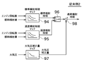
- a standard fuel injection timing (standard injection timing) is calculated by applying a standard injection timing map 91 to the engine speed and the fuel injection amount.
- the final injection timing is calculated by adding various correction amounts to the standard injection timing.
- the fuel injection timing is calculated in consideration of the engine state (steady state or transient state). Specifically, the standard injection timing map 94 is applied to the engine speed and the fuel injection amount to calculate the standard injection timing, and the transient injection timing map 95 is applied to the engine speed and the fuel injection amount. The transient injection timing is calculated.
- the switch 96 outputs the standard injection timing in the steady state, and outputs the transient injection timing in the transient state.
- the atmospheric pressure correction amount is calculated by applying the atmospheric pressure correction amount map 97 to the atmospheric pressure.
- the atmospheric pressure correction amount is added to the output value of the switch 96 by the adder 98.
- the final injection timing is calculated.
- the atmospheric pressure correction amount calculated by the atmospheric pressure correction amount map 97 does not consider whether it is a steady state or a transient state. Therefore, if the atmospheric pressure is the same, the calculated atmospheric pressure correction amount is the same regardless of whether it is a steady state or a transient state.
- the same atmospheric pressure correction amount is set in the steady state and the transient state. Therefore, for example, the correction amount is insufficient in a steady state, and misfire may occur. Alternatively, the correction amount may be too large in a transient state and exceed the allowable value of the in-cylinder pressure.
- the present invention has been made in view of the above circumstances, and a main object thereof is to provide an engine that calculates an appropriate fuel injection timing in a steady state and a transient state in a situation where atmospheric pressure is low. .
- an engine having the following configuration includes a fuel injection device, a state determination unit, an atmospheric pressure sensor, and an injection timing control unit.
- the state determination unit determines whether the engine state is a steady state or a transient state.
- the atmospheric pressure sensor detects atmospheric pressure.
- the injection timing control unit includes a steady process for calculating fuel injection timing in a steady state, a transient process for calculating fuel injection timing in a transient state, and an atmospheric pressure correction process for correcting the fuel injection timing based on atmospheric pressure. I do.
- the injection timing control unit varies the presence or absence of the atmospheric pressure correction process or the content of the atmospheric pressure correction process depending on whether the engine state is a steady state or a transient state.
- the engine has the following configuration. That is, in the steady state, the fuel injection timing calculated in the steady process is corrected with the first correction amount calculated based on the atmospheric pressure. In the transient state, the fuel injection timing calculated in the transient process is corrected with the second correction amount calculated based on the atmospheric pressure. The first correction amount and the second correction amount are different.
- the engine has the following configuration. That is, in the steady state, the fuel injection timing calculated in the steady process is corrected with the correction amount calculated based on the atmospheric pressure. In the transient state, the fuel injection timing calculated by the transient process is used without using the correction amount based on the atmospheric pressure.
- the injection timing control unit corrects the correction amount based on the atmospheric pressure when the engine state is a transient state and the atmospheric pressure detected by the atmospheric pressure sensor is within a predetermined range. It is preferable to use the fuel injection timing calculated by the transient process without using the above.
- the above control can be performed only when the atmospheric pressure is in an appropriate range (when there is no problem even if the correction amount based on the atmospheric pressure is ignored).
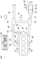
- FIG. Explanatory drawing which shows a gas flow and various sensors typically.
- the block diagram which shows the process which calculates the fuel-injection time which concerns on 1st Embodiment.
- the flowchart which shows the process of the state determination part which concerns on 1st Embodiment.
- the block diagram which shows the process which calculates the fuel-injection time which concerns on 2nd Embodiment.
- the block diagram which shows the process which calculates the fuel-injection time which concerns on a prior art example.
- the block diagram which shows the process which calculates the fuel-injection time concerning another prior art example.
- the graph which shows the change of the cylinder pressure when an altitude (atmospheric pressure) and an engine state differ.
- the engine 100 is a diesel engine and is mounted on a work machine, a ship, and the like.
- the engine 100 includes an intake pipe 20, a supercharger 21, a supercharge pipe 24, an intake throttle 25, an intake manifold 26, and a breather hose 27 as intake system members. Prepare.
- the suction pipe 20 sucks gas from the outside.
- the suction pipe 20 includes a filter that removes dust and the like in the gas.
- the supercharger 21 includes a turbine housing 22 and a compressor housing 23.
- a turbine wheel (not shown) in the turbine housing 22 is configured to rotate using exhaust gas.
- An unillustrated compressor wheel in the compressor housing 23 is connected to the same shaft 21a (FIG. 2) as the turbine wheel, and rotates as the turbine wheel rotates.
- the supercharger 21 can forcibly intake air by compressing air by rotating the compressor wheel.
- the gas sucked by the supercharger 21 flows through the supercharging pipe 24.
- One side of the supercharging pipe 24 is connected to the supercharger 21, and the other side of the supercharging pipe 24 is connected to the intake throttle 25.
- the intake throttle 25 has an intake valve.
- the intake throttle 25 can change the amount of gas supplied to the cylinder by adjusting the opening of the intake valve.
- the gas that has passed through the intake throttle 25 is sent to the intake manifold 26.
- the opening degree of the intake valve is controlled by an ECU (engine control unit) 50 shown in FIG.
- the intake manifold 26 divides the gas supplied from the intake throttle 25 into a number corresponding to the number of cylinders (four in this embodiment) and supplies it to the cylinder head 10.
- the cylinder head 10 is provided with a cylinder head cover 11 and an injector (fuel injection device) 12.
- the injector 12 injects fuel into the combustion chamber at a predetermined timing.
- the injector 12 is configured to perform main injection near the top dead center (TDC). Further, the injector 12 can perform pre-injection for noise reduction immediately before the main injection, or can perform pilot injection for NOx reduction and noise reduction at a timing before the pre-injection. Further, the injector 12 performs after injection for the purpose of reducing PM and promoting exhaust gas purification immediately after the main injection, or performing post injection for the purpose of raising the temperature at a later timing of the after injection. can do.
- TDC top dead center
- Motive power can be generated by injecting fuel and driving the piston in this way. Blow-by gas and exhaust gas are generated in the combustion chamber.
- the breather hose 27 supplies blow-by gas generated in the combustion chamber to the suction pipe 20. Thereby, it can prevent that unburned gas is discharged
- an intake pressure sensor 51 and an intake temperature sensor 52 are attached to the intake manifold 26.
- the intake pressure sensor 51 detects the gas pressure in the intake manifold 26 and outputs it to the ECU 50.
- the ECU 50 recognizes the input pressure as the intake pressure.
- the intake air temperature sensor 52 detects the temperature of the gas in the intake manifold 26 and outputs it to the ECU 50. Note that the intake pressure sensor 51 and the intake temperature sensor 52 may be arranged not in the intake manifold 26 but in a pipe upstream of the intake manifold 26.
- the engine 100 includes an exhaust manifold 30, an exhaust pipe 31, and an exhaust gas purification device 32 as exhaust system members.
- the engine 100 provided with the exhaust gas purification device 32 is particularly referred to as an exhaust gas purification system.
- the exhaust gas purification device 32 may be arranged at a position slightly away from the engine 100.
- the exhaust manifold 30 collectively supplies exhaust gas generated in a plurality of combustion chambers to the turbine housing 22 of the supercharger 21.
- an exhaust pressure sensor 53 and an exhaust temperature sensor 54 are attached to the exhaust manifold 30.
- the exhaust pressure sensor 53 detects the gas pressure in the exhaust manifold 30 and outputs it to the ECU 50.
- the ECU 50 recognizes the input pressure as the exhaust pressure.
- the exhaust temperature sensor 54 detects the temperature of the gas in the exhaust manifold 30 and outputs it to the ECU 50.
- a part of the gas that has passed through the exhaust manifold 30 and the turbine housing 22 is supplied to the EGR device 40 via the EGR pipe 41 and the remainder is supplied to the exhaust gas purification device 32 via the exhaust pipe 31.
- the engine 100 includes an EGR device 40 as an intake system and exhaust system member.
- the EGR device 40 includes an EGR cooler 42 and an EGR valve 43.
- the EGR cooler 42 cools the exhaust gas.
- the EGR device 40 can change the amount of exhaust gas supplied to the intake manifold 26 by adjusting the opening of the EGR valve 43.
- the opening degree of the EGR valve 43 is controlled by the ECU 50.
- the ECU 50 adjusts the opening degree of the EGR valve 43 based on, for example, a differential pressure between the intake pressure and the exhaust pressure.
- the exhaust gas purification device 32 purifies the exhaust gas and discharges it.
- the exhaust gas purification device 32 includes an oxidation catalyst 33 and a filter 34.
- the oxidation catalyst 33 is made of platinum or the like, and is a catalyst for oxidizing (combusting) unburned fuel, carbon monoxide, nitrogen monoxide and the like contained in the exhaust gas.
- the filter 34 is configured as a wall flow type filter, for example, and collects PM (particulate matter) contained in the exhaust gas treated by the oxidation catalyst 33.
- the exhaust gas purification device 32 is provided with a temperature sensor 55 and a differential pressure sensor 56.
- the temperature sensor 55 detects the temperature in the exhaust gas purification device 32.
- the differential pressure sensor 56 detects a pressure difference between the upstream side of the filter 34 (the exhaust downstream side of the oxidation catalyst 33) and the downstream side of the filter 34, and outputs the detected pressure difference to the ECU 50.
- the ECU 50 calculates the amount of PM deposited on the filter 34 based on the detection result of the differential pressure sensor 56.
- the oxidation reaction occurring in the exhaust gas purification device 32 is calculated based on the operation history of the engine 100, and the PM deposition amount is obtained based on the oxidation reaction. You can also.
- the engine 100 includes an atmospheric pressure sensor 57 (FIG. 2).
- the intake air temperature sensor 52 detects atmospheric pressure and outputs it to the ECU 50.
- the ECU 50 controls each part of engine 100.
- the ECU 50 includes a state determination unit 58 and an injection timing control unit 59 as a configuration for controlling the fuel injection timing. The processing performed by these will be described later.
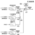
- FIG. 3 shows the processing performed by the ECU 50 as a function.
- the ECU 50 calculates the standard injection timing by applying the standard injection timing map 61 to the engine speed and the fuel injection amount (steady state processing).
- the standard injection timing is a value that is a base of the fuel injection timing when the engine state is a steady state.
- the ECU 50 calculates the correction amount by applying the atmospheric pressure correction amount map 62 to the engine speed and the fuel injection amount, and applies the atmospheric pressure correction coefficient curve 63 to the atmospheric pressure. To calculate the correction coefficient.
- the atmospheric pressure correction amount is calculated by integrating the two by the integrator 64 (atmospheric pressure correction processing).
- the standard injection timing and the atmospheric pressure correction amount are added by the adder 65 and output to the switch 67.
- the ECU 50 calculates the transient injection timing by applying the transient injection timing map 66 to the engine speed and the fuel injection amount (transient processing).
- the transient injection timing is a value that is a base of the fuel injection timing when the engine state is a transient state.
- the transient injection timing is output to the switch 67.
- the state determination unit 58 performs various determination processes and switches the switch 67 according to the determination result. Hereinafter, the processing performed by the state determination unit 58 will be described with reference to the flowchart of FIG.
- the state determination unit 58 first determines whether or not the engine state is a transient state (S101). This determination is performed based on, for example, at least one of the change amount of the accelerator opening, the change amount of the fuel injection amount, and the change amount of the engine speed.
- the standard output value (a value obtained by adding the atmospheric pressure correction amount to the standard injection timing) Is switched from the switch 67 (S102).
- the state determination unit 58 determines whether or not the atmospheric pressure detected by the atmospheric pressure sensor is within a predetermined range (S103). This process determines the magnitude of the influence of atmospheric pressure.
- the state determination unit 58 determines that the influence of the atmospheric pressure is small, and the switch 67 so that the output value on the transient side (transient injection timing) is output from the switch 67. (S104). If the atmospheric pressure is not within the predetermined range, the state determination unit 58 performs processing such as using another correction method (S105).
- the ECU 50 performs other corrections on the final injection timing output from the switch 67 (for example, when the turbo lag is generated, the correction amount is applied) to control the injector 12 and the like.
- correction based on atmospheric pressure is performed only in a steady state. Accordingly, since the correction amount based on the transient state and the correction amount based on the atmospheric pressure are not applied twice, it is possible to prevent the over-advance angle and prevent the in-cylinder pressure from exceeding the allowable value.
- the second embodiment is different from the first embodiment in that correction based on atmospheric pressure is performed even during transition.
- correction based on atmospheric pressure is performed even during transition.
- ECU 50 calculates the standard injection timing by applying the standard injection timing map 71 to the engine speed and the fuel injection amount in the same manner as described above (steady process). Similarly to the above, the ECU 50 calculates the correction amount by applying the standard atmospheric pressure correction amount map 72 to the engine speed and the fuel injection amount, and applies the standard atmospheric pressure correction coefficient curve 73 to the atmospheric pressure to correct the correction coefficient. Is calculated. A standard atmospheric pressure correction amount is calculated by integrating both by the integrator 74 (atmospheric pressure correction processing). The standard atmospheric pressure correction amount map 72 and the standard atmospheric pressure correction coefficient curve 73 are created for a steady state.
- the standard injection timing and the standard atmospheric pressure correction amount are added by the adder 75 and output to the switch 81.
- the ECU 50 calculates the transient injection timing by applying the transient injection timing map 76 to the engine speed and the fuel injection amount in the same manner as described above (transient processing).
- the ECU 50 calculates the correction amount by applying the transient atmospheric pressure correction amount map 77 to the engine speed and the fuel injection amount, and calculates the correction coefficient by applying the transient atmospheric pressure correction coefficient curve 78 to the atmospheric pressure.
- a transient atmospheric pressure correction amount is calculated (atmospheric pressure correction processing).
- the transient atmospheric pressure correction amount map 77 and the transient atmospheric pressure correction coefficient curve 78 are created for the transient state. Therefore, even if the atmospheric pressure is the same, the standard atmospheric pressure correction amount and the transient atmospheric pressure correction amount have different values.
- the transient injection timing and the transient atmospheric pressure correction amount are added by the adder 80 and output to the switch 81.
- the state determination unit 58 determines whether the engine state is a steady state or a transient state, and in the case of the steady state, a standard-side output value (a value obtained by adding the standard atmospheric pressure correction amount to the standard injection timing) is output from the switch 81.
- the switch 81 is switched as described above.
- the state determination unit 58 switches the switch 81 so that an output value on the transient side (a value obtained by adding the transient atmospheric pressure correction amount to the transient injection timing) is output from the switch 81. .
- the stability of ignition is improved by adjusting the injection timing.
- Various processes are known as processes for improving the stability of ignition. For example, by lowering the pressure of the common rail, the evaporation of spray can be slowed and the latent heat of vaporization can be suppressed, so that the stability of ignition can be improved.
- the engine may be configured as follows. That is, the engine includes a common rail device, a state determination unit that determines whether the engine state is a steady state or a transient state, an atmospheric pressure sensor that detects atmospheric pressure, a steady process that calculates a common rail pressure in a steady state, A common rail pressure control unit that performs a transient process for calculating the common rail pressure in a state and an atmospheric pressure correction process for correcting the common rail pressure based on the atmospheric pressure.
- the presence or absence of the atmospheric pressure correction process or the content of the atmospheric pressure correction process is different between the case of the above and the case of a transient state.
- the common rail pressure control unit corrects the common rail pressure calculated in the steady process with the first correction amount calculated based on the atmospheric pressure.
- the common rail pressure control unit performs the transient process.
- the calculated common rail pressure may be corrected with a second correction amount calculated based on atmospheric pressure, and the first correction amount and the second correction amount may be different.
- the common rail pressure control unit corrects the common rail pressure calculated in the steady process with a correction amount calculated based on atmospheric pressure in a steady state, and a correction amount based on atmospheric pressure in a transient state.
- the common rail pressure calculated by the transient process may be used without using the above.
- the common rail pressure control unit does not use the correction amount based on the atmospheric pressure when the engine state is a transient state and the atmospheric pressure detected by the atmospheric pressure sensor is within a predetermined range.
- the common rail pressure calculated by the transient process may be used.
- the in-cylinder temperature can be increased and the ignition stability can be improved. Note that the stability of ignition can be improved even when the pre-injection interval is shortened. Moreover, since the injection amount per injection can be reduced by performing pilot injection, the temperature of spray can be raised and the stability of ignition can be improved.
- the engine may be configured as follows. That is, the engine includes a fuel injection device, a state determination unit that determines whether the engine state is in a steady state or a transient state, an atmospheric pressure sensor that detects atmospheric pressure, and “implementation of pre-injection and pilot injection in a steady state” Steadily processing for calculating “whether or not, injection amount / injection timing in case of implementation”, “in the presence or absence of pre-injection and pilot injection, in injection state / injection timing in case of implementation” in transient state ”
- a fuel injection control unit that performs a transient process for calculating the pressure, and an atmospheric pressure correction process that corrects “whether pre-injection or pilot injection is performed, or any of the injection amount / injection timing in the case of execution” based on the atmospheric pressure
- the fuel injection control unit varies the presence or absence of the atmospheric pressure correction process or the content of the atmospheric pressure correction process depending on whether the engine state is a steady state or a transient state.
- the fuel injection control unit calculates whether or not the pre-injection and the pilot injection are performed and any one of the injection amount and the injection timing in the case of the steady process based on the atmospheric pressure.
- the “presence / absence of pre-injection and pilot injection, or any of the injection amount / injection timing in the case of execution” calculated in the transient process is large.
- Correction may be performed with a second correction amount calculated based on the atmospheric pressure, and the first correction amount and the second correction amount may be different.
- the fuel injection control unit sets the “presence / absence of pre-injection and pilot injection, or injection amount / injection timing in execution” calculated in the steady process to atmospheric pressure.
- the correction amount calculated based on the atmospheric pressure is used without using the correction amount based on the atmospheric pressure.
- One of the quantity and the injection timing may be used.
- the fuel injection control unit does not use the correction amount based on the atmospheric pressure when the engine state is a transient state and the atmospheric pressure detected by the atmospheric pressure sensor is within a predetermined range.
- it may have a feature of using “whether or not pre-injection and pilot injection are performed and any of the injection amount and the injection timing in the case of execution” calculated in the transient process.
- the stability of ignition can be appropriately improved by using them appropriately based on the priority matters and conditions. This proper use may be automatically performed on the ECU 50 side or may be instructed by the user.
- the engine 100 includes the injector 12, the state determination unit 58, the atmospheric pressure sensor 57, and the injection timing control unit 59.
- the state determination unit 58 determines whether the engine state is a steady state or a transient state.
- the atmospheric pressure sensor 57 detects atmospheric pressure.
- the injection timing control unit 59 includes a steady process for calculating the fuel injection timing in the steady state, a transient process for calculating the fuel injection timing in the transient state, and an atmospheric pressure correction process for correcting the fuel injection timing based on the atmospheric pressure. I do.
- the injection timing control unit 59 changes the presence / absence of the atmospheric pressure correction process depending on whether the engine state is a steady state or a transient state (first embodiment), or changes the content of the atmospheric pressure correction process ( Second embodiment).
- the method for determining whether the state is a steady state or a transient state is arbitrary, and may be determined using a method other than the method described above.
- the correction amount and the correction coefficient are individually calculated to obtain the atmospheric pressure correction amount.
- the atmospheric pressure correction amount may be obtained based only on the atmospheric pressure.
- the configuration of the engine 100 and the processing performed by the ECU 50 can be changed as appropriate without departing from the spirit of the present invention.
- the present invention can be applied to a naturally aspirated engine.
- Injector fuel injection device 50 ECU 57 atmospheric pressure sensor 58 state determination unit 59 injection timing control unit 61 standard injection timing map 62 atmospheric pressure correction amount map 63 atmospheric pressure correction coefficient curve 66 transient injection timing map
Landscapes
- Engineering & Computer Science (AREA)
- Chemical & Material Sciences (AREA)
- Combustion & Propulsion (AREA)
- Mechanical Engineering (AREA)
- General Engineering & Computer Science (AREA)
- Electrical Control Of Air Or Fuel Supplied To Internal-Combustion Engine (AREA)
- Combined Controls Of Internal Combustion Engines (AREA)
Abstract
Priority Applications (5)
| Application Number | Priority Date | Filing Date | Title |
|---|---|---|---|
| EP15754534.4A EP3112642A4 (fr) | 2014-02-26 | 2015-02-25 | Moteur |
| CA2939475A CA2939475A1 (fr) | 2014-02-26 | 2015-02-25 | Moteur |
| CN201580004667.1A CN105917104B (zh) | 2014-02-26 | 2015-02-25 | 发动机 |
| US15/121,349 US10502156B2 (en) | 2014-02-26 | 2015-02-25 | Engine controller based on atmospheric pressure |
| KR1020167015296A KR101833349B1 (ko) | 2014-02-26 | 2015-02-25 | 엔진 |
Applications Claiming Priority (2)
| Application Number | Priority Date | Filing Date | Title |
|---|---|---|---|
| JP2014-035327 | 2014-02-26 | ||
| JP2014035327A JP6129097B2 (ja) | 2014-02-26 | 2014-02-26 | ディーゼルエンジン |
Publications (1)
| Publication Number | Publication Date |
|---|---|
| WO2015129262A1 true WO2015129262A1 (fr) | 2015-09-03 |
Family
ID=54008596
Family Applications (1)
| Application Number | Title | Priority Date | Filing Date |
|---|---|---|---|
| PCT/JP2015/000949 WO2015129262A1 (fr) | 2014-02-26 | 2015-02-25 | Moteur |
Country Status (7)
| Country | Link |
|---|---|
| US (1) | US10502156B2 (fr) |
| EP (1) | EP3112642A4 (fr) |
| JP (1) | JP6129097B2 (fr) |
| KR (1) | KR101833349B1 (fr) |
| CN (1) | CN105917104B (fr) |
| CA (1) | CA2939475A1 (fr) |
| WO (1) | WO2015129262A1 (fr) |
Families Citing this family (1)
| Publication number | Priority date | Publication date | Assignee | Title |
|---|---|---|---|---|
| JP6354524B2 (ja) * | 2014-11-06 | 2018-07-11 | スズキ株式会社 | 燃料噴射装置 |
Citations (4)
| Publication number | Priority date | Publication date | Assignee | Title |
|---|---|---|---|---|
| JPS6275050A (ja) * | 1985-09-27 | 1987-04-06 | Toyota Motor Corp | デイ−ゼル機関の燃料噴射時期制御装置 |
| JPH05272374A (ja) * | 1992-03-27 | 1993-10-19 | Mitsubishi Electric Corp | 内燃機関の電子制御装置 |
| JPH11193737A (ja) * | 1997-12-26 | 1999-07-21 | Suzuki Motor Corp | エンジンの燃料制御装置 |
| JP2000220501A (ja) * | 1999-01-29 | 2000-08-08 | Nissan Motor Co Ltd | エンジンの制御装置 |
Family Cites Families (9)
| Publication number | Priority date | Publication date | Assignee | Title |
|---|---|---|---|---|
| JP2813397B2 (ja) | 1989-08-03 | 1998-10-22 | ローベルト・ボッシュ・ゲゼルシャフト・ミット・ベシュレンクテル・ハフツング | 内燃機関の噴射開始目標値を発生する装置 |
| JPH10318019A (ja) * | 1997-05-22 | 1998-12-02 | Kokusan Denki Co Ltd | 内燃機関用燃料噴射制御方法及び装置 |
| US6325050B1 (en) * | 2000-03-24 | 2001-12-04 | General Electric Company | Method and system for controlling fuel injection timing in an engine for powering a locomotive |
| JP2002349335A (ja) | 2001-03-21 | 2002-12-04 | Mazda Motor Corp | 筒内噴射式エンジンの制御装置 |
| JP2003206789A (ja) * | 2002-01-15 | 2003-07-25 | Mitsubishi Electric Corp | 内燃機関の燃料噴射制御装置 |
| EP1584809B1 (fr) * | 2003-11-19 | 2018-10-17 | Ford Global Technologies, LLC | Procédé pour la régénération d'un équipement de post traitement des gaz d'échappement |
| JP3933172B2 (ja) * | 2005-07-15 | 2007-06-20 | いすゞ自動車株式会社 | 排気ガス浄化システムの制御方法及び排気ガス浄化システム |
| JP2011163251A (ja) | 2010-02-12 | 2011-08-25 | Mitsubishi Heavy Ind Ltd | ディーゼルエンジンの燃料噴射制御装置および方法 |
| DE112011100766B4 (de) * | 2011-08-10 | 2021-08-12 | Toyota Jidosha Kabushiki Kaisha | Steuervorrichtung für Verbrennungsmotor |
-
2014
- 2014-02-26 JP JP2014035327A patent/JP6129097B2/ja active Active
-
2015
- 2015-02-25 EP EP15754534.4A patent/EP3112642A4/fr not_active Withdrawn
- 2015-02-25 CN CN201580004667.1A patent/CN105917104B/zh not_active Expired - Fee Related
- 2015-02-25 CA CA2939475A patent/CA2939475A1/fr not_active Abandoned
- 2015-02-25 US US15/121,349 patent/US10502156B2/en not_active Expired - Fee Related
- 2015-02-25 WO PCT/JP2015/000949 patent/WO2015129262A1/fr active Application Filing
- 2015-02-25 KR KR1020167015296A patent/KR101833349B1/ko active IP Right Grant
Patent Citations (4)
| Publication number | Priority date | Publication date | Assignee | Title |
|---|---|---|---|---|
| JPS6275050A (ja) * | 1985-09-27 | 1987-04-06 | Toyota Motor Corp | デイ−ゼル機関の燃料噴射時期制御装置 |
| JPH05272374A (ja) * | 1992-03-27 | 1993-10-19 | Mitsubishi Electric Corp | 内燃機関の電子制御装置 |
| JPH11193737A (ja) * | 1997-12-26 | 1999-07-21 | Suzuki Motor Corp | エンジンの燃料制御装置 |
| JP2000220501A (ja) * | 1999-01-29 | 2000-08-08 | Nissan Motor Co Ltd | エンジンの制御装置 |
Non-Patent Citations (1)
| Title |
|---|
| See also references of EP3112642A4 * |
Also Published As
| Publication number | Publication date |
|---|---|
| CA2939475A1 (fr) | 2015-09-03 |
| CN105917104B (zh) | 2019-06-18 |
| KR101833349B1 (ko) | 2018-02-28 |
| EP3112642A4 (fr) | 2017-11-08 |
| JP2015161185A (ja) | 2015-09-07 |
| US20160363086A1 (en) | 2016-12-15 |
| KR20160081983A (ko) | 2016-07-08 |
| JP6129097B2 (ja) | 2017-05-17 |
| US10502156B2 (en) | 2019-12-10 |
| EP3112642A1 (fr) | 2017-01-04 |
| CN105917104A (zh) | 2016-08-31 |
Similar Documents
| Publication | Publication Date | Title |
|---|---|---|
| JP2011027059A (ja) | エンジンの制御装置 | |
| WO2014196035A1 (fr) | Dispositif de contrôle pour moteur à combustion interne | |
| JP2007278223A (ja) | 筒内噴射型火花点火式内燃機関の制御装置 | |
| JP2005240755A (ja) | エンジンの燃料噴射制御装置 | |
| JP6129097B2 (ja) | ディーゼルエンジン | |
| US20150167559A1 (en) | Control device for internal combustion engine | |
| JP5692130B2 (ja) | 内燃機関制御装置 | |
| JP5695878B2 (ja) | 内燃機関の燃焼制御装置及び方法 | |
| JP5260770B2 (ja) | エンジンの制御装置 | |
| JP6473390B2 (ja) | エンジン | |
| JP2016000970A (ja) | 内燃機関の制御装置 | |
| WO2010106828A1 (fr) | Dispositif de commande pour moteur à combustion interne | |
| JP2009091920A (ja) | 燃料供給異常判定方法およびその装置 | |
| JP2016160921A (ja) | 内燃機関の燃焼制御装置 | |
| JP2012007541A (ja) | 内燃機関の制御装置 | |
| KR20180067898A (ko) | 엔진의 소기 제어 시의 배기 가스 저감 방법 | |
| JP2007239644A (ja) | 内燃機関の排気空燃比推定装置 | |
| JP5467928B2 (ja) | 内燃機関の点火時期補正制御方法 | |
| WO2014080455A1 (fr) | Dispositif de commande pour moteur diesel | |
| JP6311363B2 (ja) | 内燃機関の制御装置 | |
| JP2015137642A (ja) | 内燃機関のNOx量推定方法 | |
| JP2010144677A (ja) | 内燃機関の燃料噴射制御装置及び制御方法 | |
| JP2015197096A (ja) | 内燃機関の制御装置 | |
| JP2008038623A (ja) | 内燃機関の排気浄化装置、及び方法 | |
| JP2008038625A (ja) | 内燃機関の排気浄化装置、及び方法 |
Legal Events
| Date | Code | Title | Description |
|---|---|---|---|
| 121 | Ep: the epo has been informed by wipo that ep was designated in this application |
Ref document number: 15754534 Country of ref document: EP Kind code of ref document: A1 |
|
| ENP | Entry into the national phase |
Ref document number: 20167015296 Country of ref document: KR Kind code of ref document: A |
|
| ENP | Entry into the national phase |
Ref document number: 2939475 Country of ref document: CA |
|
| WWE | Wipo information: entry into national phase |
Ref document number: 15121349 Country of ref document: US |
|
| NENP | Non-entry into the national phase |
Ref country code: DE |
|
| REEP | Request for entry into the european phase |
Ref document number: 2015754534 Country of ref document: EP |
|
| WWE | Wipo information: entry into national phase |
Ref document number: 2015754534 Country of ref document: EP |