WO2015129113A1 - スイッチ - Google Patents
スイッチ Download PDFInfo
- Publication number
- WO2015129113A1 WO2015129113A1 PCT/JP2014/081270 JP2014081270W WO2015129113A1 WO 2015129113 A1 WO2015129113 A1 WO 2015129113A1 JP 2014081270 W JP2014081270 W JP 2014081270W WO 2015129113 A1 WO2015129113 A1 WO 2015129113A1
- Authority
- WO
- WIPO (PCT)
- Prior art keywords
- base
- sliding body
- coil spring
- operation lever
- switch
- Prior art date
- Legal status (The legal status is an assumption and is not a legal conclusion. Google has not performed a legal analysis and makes no representation as to the accuracy of the status listed.)
- Ceased
Links
Images








Classifications
-
- H—ELECTRICITY
- H01—ELECTRIC ELEMENTS
- H01H—ELECTRIC SWITCHES; RELAYS; SELECTORS; EMERGENCY PROTECTIVE DEVICES
- H01H21/00—Switches operated by an operating part in the form of a pivotable member acted upon directly by a solid body, e.g. by a hand
- H01H21/02—Details
-
- H—ELECTRICITY
- H01—ELECTRIC ELEMENTS
- H01H—ELECTRIC SWITCHES; RELAYS; SELECTORS; EMERGENCY PROTECTIVE DEVICES
- H01H3/00—Mechanisms for operating contacts
- H01H3/32—Driving mechanisms, i.e. for transmitting driving force to the contacts
-
- H—ELECTRICITY
- H01—ELECTRIC ELEMENTS
- H01H—ELECTRIC SWITCHES; RELAYS; SELECTORS; EMERGENCY PROTECTIVE DEVICES
- H01H3/00—Mechanisms for operating contacts
- H01H3/32—Driving mechanisms, i.e. for transmitting driving force to the contacts
- H01H3/46—Driving mechanisms, i.e. for transmitting driving force to the contacts using rod or lever linkage, e.g. toggle
-
- H—ELECTRICITY
- H01—ELECTRIC ELEMENTS
- H01H—ELECTRIC SWITCHES; RELAYS; SELECTORS; EMERGENCY PROTECTIVE DEVICES
- H01H13/00—Switches having rectilinearly-movable operating part or parts adapted for pushing or pulling in one direction only, e.g. push-button switch
- H01H13/50—Switches having rectilinearly-movable operating part or parts adapted for pushing or pulling in one direction only, e.g. push-button switch having a single operating member
- H01H13/52—Switches having rectilinearly-movable operating part or parts adapted for pushing or pulling in one direction only, e.g. push-button switch having a single operating member the contact returning to its original state immediately upon removal of operating force, e.g. bell-push switch
- H01H2013/525—Switches having rectilinearly-movable operating part or parts adapted for pushing or pulling in one direction only, e.g. push-button switch having a single operating member the contact returning to its original state immediately upon removal of operating force, e.g. bell-push switch using a return spring acting perpendicular to the actuating direction
Definitions
- the present invention relates to a switch, particularly a highly productive switch.
- Patent Document 1 Japanese Utility Model Publication No. 63-20335
- a movable body 27 that moves on the common terminal 11 and the first and second terminals 12 and 13 formed on the substrate 17 is provided, and the movable body 27 is moved by operating the lever 32 to move the first body. The conduction state between the second terminals 12 and 13 is switched.
- the movable body 27 is attached from above the substrate 17 into which the common terminal 11 and the first and second terminals 12 and 13 are press-fitted from below, and the substrate 17 is attached to one side surface of the case 25. It is inserted from the formed opening and arranged at a predetermined position inside the case. And after arrange
- the conventional switch needs to be mounted with components from multiple directions, it takes time to assemble. In particular, there is a problem in that the components are easily dropped during the assembly and the productivity is low.
- an object of the present invention is to provide a switch that is easy to assemble and has high productivity.
- a switch according to the present invention is adjacent to a base and a plurality of fixed contact terminals having fixed contacts protruding from the upper surface of the base at an interval so as to form at least one row.
- a movable contact piece for conducting the fixed contact ; a sliding body disposed on the upper surface of the base so as to be slidable along the row of the fixed contact terminals; and a rotatably supported on the upper surface of the base.
- An operation lever that presses and slides the sliding body, and is assembled to the sliding body, and when the sliding body is moved by the operating lever, the sliding body is returned toward the operating lever.
- a switch comprising: a coil spring that biases the operation lever; an operation hole for operating the operation lever; and a cover that has a pressing portion for pressing the operation lever and covers the base. From above the base, the fixed contact terminal, the sliding body, the operating lever and the coil spring are attached to the base, and the sliding body is pressed against the operating lever for positioning, and the cover is placed on the base from above. By attaching, the operation lever is pressed by the pressing portion of the cover, and the operation lever is rotated to an initial position.
- each component can be attached to the base in one direction, that is, from above the base, so that it can be easily assembled. For this reason, for example, it is easy to automate production and a switch with high productivity can be obtained.
- the operation lever extends so as to form a certain angle with a lever main body rotatably supported by the base, and presses the sliding body. It is good also as a structure which has a press arm part for making it slide, and presses the said press arm part with the said press part by attaching the said cover to the said base from upper direction.
- the pressing portion forms a certain angle with the lever body, the pressing arm portion can be reliably pressed by the pressing portion when the cover is attached to the base from above the base.
- the operation lever may have a curved surface that can rotate while maintaining a pressure contact state with the sliding body at least at a part around the rotation axis of the lever body.
- the operating lever since the operating lever has a curved surface that can be rotated while maintaining a pressure contact state with the sliding body, the cover can be attached to the base while the sliding body is maintained at a desired position. . As a result, an easily assembled switch can be obtained.
- the sliding body may have a pressing protrusion having a tapered surface that comes into pressure contact with the operating lever.
- the operation lever can be reliably rotated while maintaining the pressure contact state with the sliding body. As a result, an easily assembled switch can be obtained.
- a coil spring accommodating portion for accommodating the coil spring is provided on the upper part of the sliding body, and the coil spring accommodating portion may have a box shape opened. .
- the coil spring can be attached from above the base, a switch that can be easily assembled can be obtained.
- a support rib is provided on the inner surface of the cover so as to obtain a return force that compresses the one end of the coil spring by pressing and compressing the slide body toward the operation lever. It is good also as a structure.
- the support rib And the coil spring may be in contact with each other.
- FIG. 7 is a perspective view for explaining a method of assembling the switch of FIG. 1 following FIG. 6.
- FIG. 8 is a perspective view for explaining a method of assembling the switch of FIG. 1 following FIG. 7.
- FIG. 9 is a perspective view for explaining a method of assembling the switch of FIG. 1 following FIG. 8.
- FIG. 10 is a perspective view for explaining a method of assembling the switch of FIG. 1 following FIG. 9. It is a perspective view for demonstrating the assembly method of the switch of FIG. 1 following FIG.
- FIG. 12 is a perspective view for explaining a method of assembling the switch of FIG. 1 following FIG. 11.
- FIG. 13 is a perspective view for explaining a method of assembling the switch of FIG. 1 following FIG. 12.
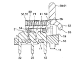
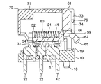
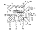
- FIG. 15 is a longitudinal sectional view for explaining the assembly state of the switch shown in FIG. 14 following FIG. 14 in more detail.
- FIG. 15 is a longitudinal sectional view for explaining in more detail the assembled state of the switch shown in FIG. 14 following FIG. 15.
- FIG. 15 is a longitudinal sectional view for explaining in more detail the assembled state of the switch shown in FIG. 14 following FIG. 15.
- FIG. 15 is a longitudinal sectional view for explaining in more detail the assembled state of the switch shown in FIG.
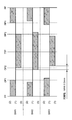
- FIG. 17 is a longitudinal sectional view for explaining in more detail the assembled state of the switch shown in FIG. 14 following FIG. 16. It is a timing chart which shows ON / OFF of the switch of FIG.
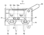
- FIG. 19 is a side perspective view illustrating the switch in the FP state in FIG. 18.
- FIG. 19 is a side perspective view showing the switch in the OP1 (RP1) state in FIG. 18.
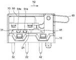
- FIG. 19 is a side perspective view illustrating the switch in the OP2 (RP2) state in FIG. 18.
- FIG. 19 is a side perspective view illustrating the switch in the TTP state in FIG. 18.
- the switch of this embodiment includes a base 10, a sliding body 50 provided on the base 10, and a cover 70 provided so as to cover the base 10. .
- the base 10 is provided with three sets of common fixed contact terminals 20, first and second fixed contact terminals 30 and 40, and an operation lever 60.
- the sliding body 50 is provided with a coil spring 80 as shown in FIG.
- the base 10 has a planar rectangular shape, and a terminal hole row 11 for press-fitting the common fixed contact terminal 20 and the first and second fixed contact terminals 30 and 40 on the upper surface thereof, and a sliding body 50.
- the terminal hole array 11 includes a common terminal hole 11a for press-fitting the common fixed contact terminal 20, a first terminal hole 11b for press-fitting the first fixed contact terminal 30, and a second fixed contact terminal 40. It is comprised with the 2nd terminal hole 11c for press-fitting.
- the common terminal hole 11a and the first and second terminal holes 11b and 11c are arranged such that the common terminal hole 11a is located between the first and second terminal holes 11b and 11c.
- the common fixed contact terminal 20 and the first and second fixed contact terminals 30 and 40 are press-fitted, the common fixed contact terminal 20 and the first and second fixed contact terminals 30 and 40 are aligned in a line. It is configured.
- the first and second terminal holes 11b and 11c are arranged symmetrically around the common terminal hole 11a.
- two guide grooves 12 are provided on the upper surface of the base 10, and are arranged between the adjacent terminal hole rows 11 so as to be parallel to the terminal hole rows 11. .
- the sliding body 50 is configured to be slidable along the extending direction X of the guide groove 12. That is, the extending direction X of the guide groove 12 is the sliding direction X of the sliding body 50.
- each of the pair of support portions 13 has a plate shape in which a corner portion of the tip is chamfered, and protrudes so as to face the upper surface edge portion of the opposite side of the base 10.
- the support portion 13 includes a support hole 14 for rotatably supporting the operation lever 60, and a mounting groove 15 communicating with the support hole 14 from the tip to the inward surface of the support portion 13. And have.
- the bottom surface of the mounting groove 15 is a tapered surface where the groove gradually becomes shallower from the tip of the support portion 13 toward the support hole 14. For this reason, the operation lever 60 is easy to attach and difficult to remove.
- Locating protrusions 19 project from the upper surface edge of the base 10 located between the pair of support portions 13. Further, as shown in FIG. 4, unevenness corresponding to the shape of the cover 70 is provided on the outer peripheral edge portion of the upper surface of the base 10.
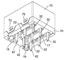
- the base 10 has a pair of positioning projections 16 for positioning the switch on a substrate or the like on each back side of the support portion 13 on the bottom surface thereof.
- a groove 16 a is provided for collecting shavings generated when the positioning protrusion 16 is inserted into a substrate or the like.
- a flux preventing recess 17 is juxtaposed at the base of the terminal hole array 11 on the bottom surface of the base 10.
- the base 10 has two attachment projections 18 on the side surfaces parallel to the extending direction X of the guide grooves 12 among the side surfaces.
- the cover 70 can be integrated with the base 10 by fitting the mounting protrusion 18 into a mounting hole 72 of the cover 70 described later.
- the common fixed contact terminal 20 has a common fixed contact 21 at its upper end and a common fixed terminal portion 22 at its lower end.
- the common fixed contact terminal 20 is press-fitted into the common terminal hole 11 a from above the base 10, the common fixed contact 21 is exposed on the upper surface of the base 10, and the common fixed terminal portion 22 is exposed from the bottom surface of the base 10. It protrudes. Further, a taper surface for guide used when assembling the sliding body 50 is provided on the upper part of the common fixed contact 21.
- the first and second fixed contact terminals 30 and 40 have first and second fixed contacts 31 and 41 at their upper ends, and first and second fixed terminal portions 32 and 41 at their lower ends. 42.
- the first and second fixed contact terminals 30 and 40 are press-fitted into the first and second terminal holes 11 b and 11 c from above the base 10, respectively.
- the first and second fixed terminal portions 32 and 42 protrude from the bottom surface of the base 10 while being exposed on the upper surface.
- a guide tapered surface used when assembling the sliding body 50 is provided on the upper part of the first and second fixed contacts.
- the sliding body 50 includes a main body 51, a coil spring housing portion 52 for housing the coil spring 80, and a guide protrusion for guiding the sliding body 50 by being inserted into the guide groove 12. It comprises a strip 53 and a movable contact piece 54 for contacting and conducting either one of the common fixed contact terminal 20 and the first and second fixed contact terminals 30 and 40.
- the main body 51 has a planar projection and a holding projection 58 for holding the movable contact piece 54 on each of the edges parallel to the sliding direction X of the sliding body 50.
- the holding protruding portion 58 is provided so as to face the guide protrusion 53, and has a locking hole 58a for locking a locking portion 54b of a movable contact piece 54, which will be described later, at its base portion. ing.
- the locking holes 58 a are disposed at both ends in the longitudinal direction of the holding protrusion 58.
- the coil spring storage portion 52 is provided in the approximate center of the upper surface of the main body portion 51, and has a box shape opened along the sliding direction X of the sliding body 50.
- a protrusion 55 for preventing the coil spring 80 from being lifted during assembly is provided at the upper opening edge of the coil spring housing 52.
- the coil spring housing portion 52 has a pressing protrusion 59 for pressing the operation lever 60 on one end surface in the longitudinal direction.
- the pressing protrusion 59 has a tapered surface on the upper end thereof.
- the other longitudinal end face of the coil spring accommodating portion 52 is provided with a fitting groove 56 into which a support rib 71 provided on the inner surface of a cover 70 described later can be fitted.
- the guide protrusions 53 have a plate shape, and are formed on the bottom surface of the main body 51 in parallel along the slide direction X of the sliding body 50, and are respectively fitted in the guide grooves 12. It is possible to slide. Moreover, the guide protrusion 53 has the press wall 57 in the longitudinal direction edge part by the side in which the press protrusion 59 is provided, respectively. The pressing wall 57 is configured to be pressed by a pressing arm portion 62 of an operation lever 60 described later. Further, on both side surfaces of the guide protrusion 53, locking portions 53a for locking a locking portion 54b of a movable contact piece 54 described later are provided. The locking portion 53 a faces the locking hole 58 a of the holding protrusion 58.
- the movable contact piece 54 includes two movable contacts 54 a and engaging portions 54 b at both ends.
- the movable contact piece 54 is disposed in parallel to each other between the holding protrusion 58 on the bottom surface of the main body 51 and the guide protrusion 53 and between the guide protrusions 53 and 53.
- the movable contacts 54a and 54a are arranged at the same interval as the interval between the common fixed contact 21 and the first fixed contact 31 (second fixed contact 41). For this reason, by moving the sliding body 50, the conduction states of the three rows of the common fixed contact terminals 20 and the first and second fixed contact terminals 30 and 40 can be switched simultaneously.
- the movable contact 54 a has a shape capable of simultaneously contacting the common fixed contact terminal 20 and one of the first and second fixed contact terminals 30 and 40. Further, as shown in FIG. 5, the locking portion 54b can be locked to the locking hole 58a of the holding projection 58 and the locking portion 53a of the guide protrusion 53 that opposes the locking hole 58a.
- the contact piece 54 is configured to be held on the bottom surface side of the main body 51.
- the operation lever 60 has a substantially rectangular shape in cross section, and is composed of a lever main body 61 and a pressing arm 62 extending from one end of the lever main body 61. .
- the lever main body 61 has a plate shape and has curved surfaces along the rotation direction of the operation lever 60 at both ends in the longitudinal direction. Further, as shown in FIG. 5, the lever main body 61 has a shaft portion 63 for rotatably mounting the operation lever 60 on the support portion 13 of the base 10 at one end portion thereof, and a coil spring housing of the sliding body 50. And a pressing groove 66 for pressing the portion 52 against the lever main body 61. That is, the operation lever 60 rotates around the shaft portion 63 of the lever body 61 as a rotation axis, and has a curved surface around the shaft portion 63 (around the rotation axis) along the rotation direction of the operation lever 60. ing.
- the shaft portion 63 has a substantially cylindrical shape, has a pressing plane 64 on the base side thereof, and is provided on both side surfaces of the lever body 61 so as to be fitted into the support holes 14 of the base 10. Yes.
- the pushing plane 64 is configured so that the operation lever 60 can be pressed when the operation lever 60 is attached to the support portion 13. For this reason, the support part 13 of the base 10 can be elastically deformed, and the shaft part 63 can be easily fitted into the support hole 14 of the support part 13.
- the pressing groove 66 is disposed at a position where one end of the lever main body 61 can contact the pressing protrusion 59.
- the pressing arm 62 extends from the lever main body 61 so as to form a certain angle with the lever main body 61, and has a protrusion 65 for pressing the pressing wall 57 of the sliding body 50 at the tip thereof. ing.
- the cover 70 has a box shape that can be attached to the base 10, and includes an attachment hole 72 for attaching the cover 70 to the base 10 and an operation hole for operating the operation lever 60. 73 and a support hole 75 for reinforcing the support portion 13 of the base 10.
- the mounting holes 72 are arranged at both side opening edges of the cover 70 so as to be fitted to the mounting protrusions 18 of the base 10.
- the operation hole 73 is disposed at a corner of the upper surface of the cover 70, and is provided so that a part of the upper surface and side surface of the cover 70 is opened.
- a notch 74 is provided below the operation hole 73 so that the positioning protrusion 19 of the base 10 can be fitted therein.
- a pressing portion 76 is provided between the operation hole 73 and the cutout portion 74.
- the support holes 75 are arranged on both sides of the operation hole 73 on the upper surface of the cover 70. As shown in FIG. 1, the support hole 75 is configured to support the support portion 13 by inserting the upper end of the support portion 13 when the cover 70 is attached to the base 10. For this reason, since the support part 13 can be reinforced in the switch after an assembly, the positioning accuracy of the operation lever 60 can be improved.
- support ribs 71 are provided on the inner surface of the cover 70.
- the support rib 71 is disposed in the center of the short side of the cover 70 on the side facing the operation hole 73, and is fitted into the fitting groove 56 of the coil spring housing portion 52 of the sliding body 50 when the switch is assembled. Is done. Note that reinforcing ribs (not shown) are provided on both sides of the support rib 71.
- the coil spring 80 has a natural length slightly longer than the length in the longitudinal direction of the coil spring accommodating portion 52 of the sliding body 50.
- the common fixed contact terminal 20 and the first and second fixed contact terminals 30 and 40 are press-fitted into the terminal hole row 11 of the base 10 from the upper surface of the base 10 to form three sets of switch portions. SW1, SW2, and SW3 are formed.
- the common fixed contact 21 and the first and second fixed contacts 31, 41 are exposed from the upper surface of the base 10
- the common fixed terminal portion 22 and the first and first fixed contacts 22, 41 are exposed from the bottom surface of the base 10.
- the second fixed terminal portions 32 and 42 protrude.
- the common fixed contact terminal 20 and the first and second fixed contact terminals 30 and 40 are not limited to press-fitting, and may be attached to the base 10 by insert molding if possible.
- the movable contact piece 54 is previously placed on the three sets of switch portions SW1, SW2 and SW3.
- the sliding body 50 incorporating is attached.
- the guide protrusion 53 of the sliding body 50 is inserted into the guide groove 12 of the base 10, and the movable contact piece 54 of the sliding body 50 can contact the common fixed contact 21 and the first and second fixed contacts 31, 41. Arrange so that.
- the operation lever 60 After attaching the sliding body 50, the operation lever 60 is attached to the support portion 13 of the base 10 as shown in FIGS.
- the operation lever 60 is attached by, for example, pressing a jig against the pressing plane 64.
- the positioning accuracy of the operation lever 60 can be increased as compared with the case where the operation lever 60 is attached to the cover 70. For this reason, it is possible to increase the assembly accuracy of the switch and reduce the variation in the operating characteristics.
- the coil spring 80 is inserted from the upper opening of the coil spring storage portion 52 of the sliding body 50, and the coil spring 80 is stored inside the coil spring storage portion 52.
- the projection 55 provided in the upper opening of the coil spring housing 52 prevents the coil spring 80 from being popped out of the coil spring housing 52 during assembly.
- the protrusion 55 is a protrusion for temporarily fixing the coil spring 80 during assembly, and is provided so that the protrusion 55 and the coil spring 80 do not contact with each other in the assembled switch. For this reason, in the assembled switch, the protrusion 55 does not hinder the operation of the coil spring 80, so that the good operation of the coil spring 80 can be ensured.
- a cover 70 is attached on the base 10.
- the lever main body 61 of the operation lever 60 passes through the operation hole 73 of the cover 70, and the pressing arm portion 62 of the operation lever 60 passes through the notch 74 of the cover 70. As shown, the cover 70 is moved closer to the base 10. At this time, since the lever body 61 of the operation lever 60 is positioned at a position orthogonal to the base 10, the lever body 61 contacts the cover 70 without changing the orientation of the cover 70. Without this, the cover 70 can be brought close to the base 10.
- the operation lever 60 has a curved surface along the rotation direction at the end on the shaft portion 63 side, and the pressing protrusion 59 of the sliding body 50 has a tapered surface.
- the lever 60 can reliably rotate while maintaining the pressure contact state with the sliding body 50. That is, the sliding body 50 is hardly displaced in the sliding direction (lateral direction in FIG. 17) by the rotation of the operation lever 60.
- the operating lever is in the state of the switch shown in FIG. 60 is positioned.
- the support rib 71 is pressed against one end of the coil spring 80, the coil spring 80 is housed in the coil spring housing portion 52 in a slightly compressed state.
- the coil spring 80 is compressed by the support rib 71, the restoring force for returning the sliding body 50 toward the operation lever 60 can be increased.
- each component can be attached to the base 10 from one direction, that is, from above the base 10, and thus can be easily assembled. For this reason, for example, it is easy to automate production and a switch with high productivity can be obtained.
- the switch has three sets of switch portions SW1, SW2, and SW3, and these switch portions SW1, SW2, and SW3 are switched almost simultaneously by the operation lever 60 as shown in FIG.
- the common fixed contact terminal 20 is (1)
- the first fixed contact terminal 30 is (3)
- the second fixed contact terminal 40 is (2).
- FP on the horizontal axis indicates a switch in a state where the operation lever 60 is in the position shown in FIG. 19
- OP1 (RP1) indicates a switch in a state where the operation lever 60 is in the position shown in FIG. 20
- OP2 ( RP2) indicates a switch in a state where the operation lever 60 is in the position shown in FIG. 21
- TTP indicates a switch in a state where the operation lever 60 is in the position shown in FIG.
- the FP state shown in FIG. 19 is the initial position (return position) of the operation lever 60.
- the operation lever 60 is pushed down to the TTP state shown in FIG. 22 and stops.
- the sliding body 50 is pushed back in the Y2 direction by the elastic force of the coil spring 80, and after the RP2 state shown in FIG. 21 and the RP1 state shown in FIG. 20, the FP state shown in FIG. Return to.
- the common terminal holes 11a and the first and second terminal holes 11b and 11c of the terminal hole row 11 are arranged at equal intervals, and the common fixed contact terminal 20, the first fixed contact terminal 30, and the common fixed contact terminal 20 are arranged.
- the present invention is not limited to this. It may be set as appropriate according to the design of the switch.
- switch unit SW1, SW2, and SW3 are provided on the base 10, the present invention is not limited to this. If possible, the switch unit may be one set, two sets, or four or more sets.
- the angle formed between the lever main body 61 and the pressing arm portion 62 of the operation lever 60 is not limited as long as the pressing arm portion 62 can be pressed by the pressing portion 76 of the cover 70 when the switch is assembled. Can be changed.
- the present invention is not limited to the above-described switch but can be applied to other types of switches.
Landscapes
- Rotary Switch, Piano Key Switch, And Lever Switch (AREA)
- Push-Button Switches (AREA)
Abstract
ベース(10)と、複数の固定接点端子(20,30,40)と、摺動体(50)と、操作レバー(60)と、コイルバネ(80)と、カバー(70)とを備えるスイッチにおいて、ベース(10)の上方から、固定接点端子(20,30,40)、摺動体(50)、操作レバー(60)およびコイルバネ(80)をベース(10)に取り付けると共に、操作レバー(60)に摺動体(50)を押し当てて位置決めする。そして、ベース(10)にカバー(70)を上方から取り付けることにより、カバー(70)の押圧部(76)で操作レバー(60)を押圧し、操作レバー(60)を初期位置まで回転させる。
Description
本発明は、スイッチ、特に生産性の高いスイッチに関する。
従来、スイッチとしては、例えば、実開昭63-20335号公報(特許文献1)に記載されたものがある。このスイッチでは、基板17に形成されたコモン端子11および第1,第2端子12,13上を移動する移動体27を設け、レバー32を操作することによって移動体27を移動させて、第1,第2端子12,13間の導通状態を切り替えている。
しかしながら、前記従来のスイッチでは、コモン端子11および第1,第2端子12,13が下方から圧入された基板17の上方から移動体27を取り付けて、この基板17をケース25の一方の側面に形成された開口部から挿入し、ケース内部の所定の位置に配置している。そして、前記開口部を介して、レバー32等の他の部品をケース25内部の所定の位置に配置した後、前記開口部を塞ぐことにより組み立てている。このように、前記従来のスイッチでは、多方向から部品を取り付ける必要があったため、組み立てに手間がかかり、特に、組み立ての途中で部品が脱落し易く、生産性が低いという問題があった。
本発明は、前述の問題点に鑑み、組み立てが容易で、生産性の高いスイッチを提供することを課題とする。
本発明に係るスイッチは、前記課題を解決すべく、ベースと、前記ベースの上面に、少なくとも1つの列を成すように間隔を隔てて固定接点を突出させた複数の固定接点端子と、隣り合う前記固定接点を導通させるための可動接触片を有し、前記ベースの上面に、前記固定接点端子の列に沿ってスライド可能に配置された摺動体と、前記ベースの上面に回動可能に支持され、前記摺動体を押圧して摺動させる操作レバーと、前記摺動体に組み付けられ、前記操作レバーで前記摺動体を移動させたときに、前記摺動体を前記操作レバーに向かって復帰させるように付勢するコイルバネと、前記操作レバーを操作するための操作孔と、前記操作レバーを押圧するための押圧部とを有し、前記ベースを覆うカバーと、を備えるスイッチにおいて、前記ベースの上方から、前記固定接点端子、前記摺動体、前記操作レバーおよび前記コイルバネを前記ベースに取り付けると共に、前記操作レバーに前記摺動体を押し当てて位置決めし、前記ベースに前記カバーを上方から取り付けることにより、前記カバーの前記押圧部で前記操作レバーを押圧し、前記操作レバーを初期位置まで回転させることを特徴としている。
本発明のスイッチによれば、ベースに対して一方向、すなわち、ベースの上方から各部品を取り付けることができるので、容易に組み立てることができる。このため、例えば、生産の自動化が容易で、生産性の高いスイッチが得られる。
本発明の一実施形態としては、前記操作レバーが、前記ベースに回動可能に支持されたレバー本体と、このレバー本体と一定の角度を成すように延在し、前記摺動体を押圧して摺動させるための押圧腕部とを有し、前記ベースに前記カバーを上方から取り付けることにより、前記押圧部で、前記押圧腕部を押圧する構成としてもよい。
この実施形態によれば、押圧部がレバー本体と一定の角度を成しているので、カバーをベースの上方からベースに取り付けているときに、押圧部により、確実に押圧腕部を押圧できる。
本発明の一実施形態としては、前記操作レバーが、前記レバー本体の回動軸周りの少なくとも一部に、前記摺動体と圧接状態を維持したまま回動できる曲面を有する構成としてもよい。
この実施形態によれば、操作レバーが、摺動体と圧接状態を維持したまま回動できる曲面を有しているので、摺動体を所望の位置で維持したまま、カバーをベースに取り付けることができる。これにより、組立容易なスイッチが得られる。
本発明の一実施形態としては、前記摺動体が、前記操作レバーに押し当てたときに圧接するテーパー面を備えた押圧突起を有している構成としてもよい。
この実施形態によれば、押圧突起がテーパー面を有しているので、操作レバーが、摺動体と圧接状態を維持したまま確実に回動できる。これにより、組立容易なスイッチが得られる。
本発明の一実施形態としては、前記摺動体の上部に、前記コイルバネを収納するためのコイルバネ収納部が設けられており、前記コイルバネ収納部が開口した箱形状を有している構成としてもよい。
この実施形態によれば、コイルバネをベースの上方から取り付けることができるので、組立容易なスイッチが得られる。
本発明の一実施形態としては、前記カバーの内面に、前記コイルバネの一端に圧接して圧縮し、前記摺動体を前記操作レバーに向かって復帰させる復帰力を得るための支持リブを突設した構成としてもよい。
この実施形態によれば、摺動体の復帰位置への高い復帰力を得ることができる。
本発明の一実施形態としては、前記ベースに前記カバーを上方から取り付け、前記支持リブの下面が、前記コイルバネの上面から前記コイルバネの直径の1/3以上の位置にあるときに、前記支持リブと前記コイルバネとが当接する構成としてもよい。
この実施形態によれば、カバーをベースに取り付けるときに、コイルバネ収納部に収納されたコイルバネに、圧縮方向以外に大きな力が加わらないようにできる。このため、コイルバネのコイルバネ収納部からの脱落、浮き、あるいは噛み込みの発生を防止できる。
以下、本発明に係るスイッチの実施形態を図1ないし図22の添付図に従って説明する。
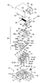
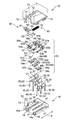
本実施形態のスイッチは、図4,図5に示すように、ベース10と、このベース10上に設けられた摺動体50と、ベース10を覆うように設けられたカバー70とを備えている。前記ベース10には、3組の共通固定接点端子20および第1,第2固定接点端子30,40と、操作レバー60とが設けられている。また、前記摺動体50には、図3に示すように、コイルバネ80が設けられている。
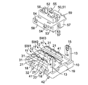
ベース10は、図4に示すように、平面方形で、その上面に、共通固定接点端子20および第1,第2固定接点端子30,40を圧入するための端子孔列11と、摺動体50を案内するためのガイド溝12と、操作レバー60を支持するための一対の支持部13とを有している。
端子孔列11は、図3に示すように、ベース10の対向する辺と平行に等間隔で、3列設けられている。そして、前記端子孔列11は、共通固定接点端子20を圧入するための共通端子孔11aと、第1固定接点端子30を圧入するための第1端子孔11bと、第2固定接点端子40を圧入するための第2端子孔11cとで構成されている。共通端子孔11aおよび第1,第2端子孔11b,11cは、共通端子孔11aが第1,第2端子孔11b,11cの間に位置するように配置されている。このため、共通固定接点端子20および第1,第2固定接点端子30,40を圧入したときに、共通固定接点端子20および第1,第2固定接点端子30,40が一列に整列するように構成されている。なお、第1,第2端子孔11b,11cは、共通端子孔11aを中心として対称に配置されている。
ガイド溝12は、図4に示すように、ベース10の上面に、2つ設けられており、隣り合う端子孔列11の間に、端子孔列11と平行になるようにそれぞれ配置されている。このガイド溝12の延在方向Xに沿って、摺動体50がスライド移動できるように構成されている。つまり、ガイド溝12の延在方向Xが、摺動体50のスライド方向Xとなっている。
一対の支持部13は、図4に示すように、各々、先端の角部が面取りされている板形状で、ベース10の対向する辺の上面縁部に、対向するように突設されている。この支持部13は、図4に示すように、操作レバー60を回動可能に支持するための支持孔14と、支持部13の内向面に先端から支持孔14に連通している取付溝15とを有している。取付溝15の底面は、支持部13の先端から支持孔14に向かって、次第に溝が浅くなるテーパー面となっている。このため、操作レバー60が取り付け易くなっていると共に、抜け難くなっている。
一対の前記支持部13の間に位置するベース10の上面縁部には、位置決め突起19が突設されている。また、ベース10の上面の外周縁部には、図4に示すように、カバー70の形状に応じた凹凸が設けられている。
また、ベース10は、図5に示すように、その底面のうち、前記支持部13の各裏側に、前記スイッチを基板等に位置決めするための一対の位置決め突部16を有している。位置決め突部16の周囲には、位置決め突部16を基板等に嵌挿したときに発生する削りくずを溜めるための溝16aが設けられている。また、ベース10の底面の端子孔列11の基部には、フラックス防止用凹所17が並設されている。
さらに、ベース10は、図4,図5に示すように、その側面のうち、ガイド溝12の延在方向Xに平行な側面に、取付突起18をそれぞれ2つ有している。この取付突起18を後述するカバー70の取付孔72を嵌合することによって、カバー70をベース10に一体化できる。
共通固定接点端子20は、図4に示すように、その上端に共通固定接点21を有し、その下端に共通固定端子部22を有している。この共通固定接点端子20は、ベース10の上方から共通端子孔11aに圧入されており、共通固定接点21がベース10の上面に露出していると共に、共通固定端子部22がベース10の底面から突出している。また、共通固定接点21の上部には、摺動体50を組み立てるときに用いる案内用のテーパー面が設けられている。
第1,第2固定接点端子30,40は、図4に示すように、その上端に第1,第2固定接点31,41を有し、その下端に第1,第2固定端子部32,42を有している。この第1,第2固定接点端子30,40は、ベース10の上方から第1,第2端子孔11b,11cにそれぞれ圧入されており、第1,第2固定接点31,41がベース10の上面に露出していると共に、第1,第2固定端子部32,42がベース10の底面から突出している。また、第1,第2固定接点の上部には、共通固定接点21と同様に、摺動体50を組み立てるときに用いる案内用のテーパー面がそれぞれ設けられている。
摺動体50は、図4,図5に示すように、本体部51と、コイルバネ80を収納するためのコイルバネ収納部52と、ガイド溝12に挿入して摺動体50を案内するためのガイド突条53と、共通固定接点端子20および第1,第2固定接点端子30,40のいずれか一方に接触して導通させるための可動接触片54と、から構成されている。
本体部51は、図4に示すように、平面方形で、摺動体50のスライド方向Xに平行な辺縁の各々に、可動接触片54を保持するための保持突出部58を有している。この保持突出部58は、ガイド突条53に対向するように突設されており、その基部に、後述する可動接触片54の係止部54bを係止するための係止孔58aを有している。この係止孔58aは、保持突出部58の長手方向の両端に配置されている。
コイルバネ収納部52は、図4に示すように、本体部51の上面略中央に設けられ、前記摺動体50のスライド方向Xに沿って、開口した箱形状である。このコイルバネ収納部52の上部開口縁部には、組立時にコイルバネ80の浮き上がりを防ぐ突起55が設けられている。また、コイルバネ収納部52は、その一方の長手方向端面に、操作レバー60を押圧するための押圧突起59を有している。押圧突起59は、図3に示すように、その先端上側にテーパー面を有している。また、コイルバネ収納部52の他方の長手方向端面には、後述するカバー70の内面に設けられた支持リブ71を嵌合可能な嵌合溝56が設けられている。
ガイド突条53は、図5に示すように、板形状で、本体部51の底面に、摺動体50のスライド方向Xに沿って平行に2つ突設されており、ガイド溝12にそれぞれ嵌め込み可能、かつ、スライド可能となっている。また、ガイド突条53は、押圧突起59が設けられている側の長手方向端部に、押圧壁57を各々有している。この押圧壁57は、後述する操作レバー60の押圧腕部62により押圧可能に構成されている。また、ガイド突条53の両側面には、後述する可動接触片54の係止部54bを係止するための係止部53aが設けられている。この係止部53aは、保持突出部58の係止孔58aに対向している。
可動接触片54は、図4,図5に示すように、2つの可動接点54aと、両端の係止部54bとで構成されている。この可動接触片54は、本体部51の底面の保持突出部58とガイド突条53との間、並びに、ガイド突条53,53の間に、相互に平行に配置されている。そして、前記可動接点54a,54aが、共通固定接点21と第1固定接点31(第2固定接点41)との間の間隔と同じ間隔で配置されている。このため、摺動体50を移動させることで、3列の共通固定接点端子20および第1,第2固定接点端子30,40の導通状態を同時に切り替えることができる。
可動接点54aは、図5に示すように、共通固定接点端子20と第1,第2固定接点端子30,40のいずれか一方とに、同時に接触できる形状を有している。また、係止部54bは、図5に示すように、保持突出部58の係止孔58aと、この係止孔58aに対向するガイド突条53の係止部53aとに係止でき、可動接触片54を本体部51の底面側に保持できるように構成されている。
操作レバー60は、図3に示すように、断面視略く字形状で、レバー本体61と、このレバー本体61の一方の端部から延在している押圧腕部62とで構成されている。
レバー本体61は、図3に示すように、板形状で、長手方向の両端に操作レバー60の回動方向に沿った曲面を有している。また、このレバー本体61は、図5に示すように、その一方の端部に操作レバー60をベース10の支持部13に回動可能に取り付けるための軸部63と、摺動体50のコイルバネ収納部52をレバー本体61に押し当てるための押圧溝66とを有している。つまり、前記操作レバー60は、レバー本体61の軸部63を回動軸として回動すると共に、軸部63周り(回動軸周り)に操作レバー60の回動方向に沿った曲面を有している。
軸部63は、図4に示すように、略円柱形状で、その基部側に押込平面64を有し、レバー本体61の両側面に、ベース10の支持孔14に嵌め込み可能に突設されている。押込平面64は、操作レバー60を支持部13に取り付けるときに、操作レバー60を押圧できるように構成されている。このため、ベース10の支持部13を弾性変形させて、軸部63を支持部13の支持孔14に容易に嵌め込むことができる。
また、押圧溝66は、図5に示すように、レバー本体61の一端部のうち、押圧突起59に当接できる位置に配置されている。
押圧腕部62は、レバー本体61から、レバー本体61と一定の角度を成すように延在しており、その先端に、摺動体50の押圧壁57を押圧するための突部65を有している。
カバー70は、図4,図5に示すように、前記ベース10に取付可能な箱形状であり、カバー70をベース10に取り付けるための取付孔72と、操作レバー60を操作するための操作孔73と、ベース10の支持部13を補強するための支持孔75とを有している。
取付孔72は、カバー70の両側開口縁部に配置され、ベース10の取付突起18に嵌合できるように設けられている。
操作孔73は、カバー70の上面角部に配置され、カバー70の上面および側面の一部が開口するように設けられている。操作孔73の下方側には、切欠部74が設けられており、ベース10の位置決め突起19が嵌合できるように設けられている。また、操作孔73と切欠部74との間に押圧部76を設けている。
支持孔75は、カバー70の上面の操作孔73の両側に配置されている。この支持孔75は、図1に示すように、カバー70をベース10に取り付けたときに、支持部13の上端が嵌挿され、支持部13を支持するように構成されている。このため、組立後のスイッチにおいて、支持部13を補強できるので、操作レバー60の位置決め精度を高めることができる。
また、カバー70の内面には、図3に示すように、支持リブ71が設けられている。この支持リブ71は、カバー70の操作孔73に対向する側の短手方向中央に配置されており、スイッチを組み立てたときに、摺動体50のコイルバネ収納部52の嵌合溝56に嵌合される。なお、支持リブ71の両側には、図示しない補強用のリブが設けられている。
コイルバネ80は、摺動体50のコイルバネ収納部52の長手方向の長さよりも若干長い自然長を有している。そして、スイッチを組み立てたときに、カバー70内部の支持リブ71に押圧されて、摺動体50を操作レバー60に向かって付勢するように圧縮されている。
次に、前記構成のスイッチの組立方法を、図6~図17を用いて説明する。
まず、図6に示すように、ベース10の上面から、共通固定接点端子20および第1,第2固定接点端子30,40をベース10の端子孔列11に圧入して、3組のスイッチ部SW1,SW2,SW3を形成する。このとき、図7に示すように、ベース10の上面から共通固定接点21および第1,第2固定接点31,41が露出し、かつ、ベース10の底面から共通固定端子部22および第1,第2固定端子部32,42が突出する。
なお、共通固定接点端子20および第1,第2固定接点端子30,40は、圧入に限らず、可能ならばインサート成形によりベース10に取り付けてもよい。
共通固定接点端子20および第1,第2固定接点端子30,40を圧入した後、図8,図9に示すように、3組のスイッチ部SW1,SW2,SW3上に、予め可動接触片54を組み込んだ摺動体50を取り付ける。このとき、摺動体50のガイド突条53をベース10のガイド溝12に挿入し、摺動体50の可動接触片54が、共通固定接点21および第1,第2固定接点31,41に接触できるように配置する。
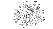
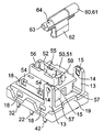
摺動体50を取り付けた後、図10,図11に示すように、操作レバー60をベース10の支持部13に取り付ける。操作レバー60の取り付けは、例えば、治具を押込平面64に押し当てることにより行う。
このように、ベース10に操作レバー60を取り付けることで、カバー70に操作レバーに取り付ける場合よりも、操作レバー60の位置決め精度を高めることができる。このため、スイッチの組立精度を高めることができ、動作特性のバラツキを低減できる。
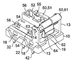
続いて、図12に示すように、摺動体50のコイルバネ収納部52の上部開口からコイルバネ80を挿入して、コイルバネ収納部52内部にコイルバネ80を収納する。このとき、コイルバネ収納部52の上部開口に設けられている突起55によって、組立中におけるコイルバネ80がコイルバネ収納部52から飛び出すことを防止している。
なお、突起55は、組立中におけるコイルバネ80の仮止め用の突起であり、組立後のスイッチにおいて、突起55とコイルバネ80とが接触しないように設けられている。このため、組立後のスイッチでは、突起55がコイルバネ80の動作を阻害することがないので、コイルバネ80の良好な動作を担保できる。
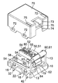
最後に、図13に示すように、ベース10上にカバー70を取り付ける。
ベース10にカバー70を取り付けるとき、まず、図14に示すように、摺動体50の押圧突起59を操作レバー60の押圧溝66に押し当てる。すると、操作レバー60のレバー本体61がベース10に対して直交する位置まで操作レバー60が回転し、位置決めされる。
そして、図15に示すように、ベース10の上方から、操作レバー60のレバー本体61がカバー70の操作孔73を通過し、操作レバー60の押圧腕部62がカバー70の切欠部74を通過するように、カバー70をベース10に近づけていく。このとき、操作レバー60のレバー本体61がベース10に対して直交する位置で操作レバー60を位置決めしているので、カバー70の向きを変えることなく、そして、レバー本体61がカバー70に接触することなく、カバー70をベース10に近づけることができる。
図16に示すように、カバー70をベース10に近づけていくと、操作レバー60の押圧腕部62の上部とカバー70の押圧部76とが接触する。さらにカバー70をベース10に近づけると、図17に示すように、押圧部76が押圧腕部62を押圧して、操作レバー60を回転させる。これにより、押圧腕部62がカバー70内部に移動して、押圧腕部62の突部65と摺動体50の押圧壁57とが接触する。
このとき、操作レバー60が、軸部63側の端部に回動方向に沿った曲面を有しており、また、摺動体50の押圧突起59が、テーパー面を有しているので、操作レバー60が、摺動体50と圧接状態を維持したまま確実に回動できる。つまり、操作レバー60の回動によって摺動体50がスライド方向(図17の横方向)に変位することは殆どない。
なお、この段階では、カバー70の支持リブ71とコイルバネ80とは当接していない。
その後、さらにカバー70をベース10に近づけると、押圧腕部62の突部65により摺動体50の押圧壁57が押圧され、摺動体50が摺動する。このとき、支持リブ71の下面が、コイルバネ80の上面からコイルバネ80の直径の1/3以上、好ましくは1/2以上の位置にあるときに、支持リブ71とコイルバネ80とが当接可能になる。これにより、カバー70をベースに取り付けるときに、コイルバネ収納部52に収納されたコイルバネ80に、圧縮方向以外に大きな力が加わらないようにできる。このため、コイルバネ80のコイルバネ収納部52からの脱落、浮き、あるいは噛み込みの発生を防止できる。
そして、カバー70の取付孔72がベース10の取付突起18に嵌め込まれ、カバー70がベース10に取り付けられると、図3に示すスイッチの状態(組立時の初期(復帰)位置)で、操作レバー60が位置決めされる。このとき、支持リブ71がコイルバネ80の一端に圧接するので、コイルバネ80は、若干圧縮された状態でコイルバネ収納部52に収納される。このように、支持リブ71によりコイルバネ80が圧縮されるので、摺動体50を操作レバー60に向かって復帰させる復帰力を高めることができる。
上述のように、前記構成のスイッチでは、ベース10に対して一方向、すなわち、ベース10の上方から各部品を取り付けることができるので、容易に組み立てることができる。このため、例えば、生産の自動化が容易で、生産性の高いスイッチが得られる。
続いて、前記構成のスイッチの動作について、図18~図22を用いて説明する。
前述のように、前記スイッチは、3組のスイッチ部SW1,SW2,SW3を有しており、図18に示すように、これらのスイッチ部SW1,SW2,SW3を操作レバー60により略同時に切り替える。なお、図18では、共通固定接点端子20を(1)、第1固定接点端子30を(3)、第2固定接点端子40を(2)として、縦軸に示している。また、横軸のFPは、操作レバー60が図19に示す位置にある状態のスイッチを示し、OP1(RP1)は、操作レバー60が図20に示す位置にある状態のスイッチを示し、OP2(RP2)は、操作レバー60が図21に示す位置にある状態のスイッチを示し、TTPは、操作レバー60が図22に示す位置にある状態のスイッチを示している。なお、図19に示すFP状態が、操作レバー60の初期位置(復帰位置)である。
まず、操作レバー60を押圧して、図19に示すFP状態のスイッチの操作レバー60を押し下げると、操作レバー60の押圧腕部62の突部65により摺動体50が押圧されて、可動接点54aがY1方向に移動する。FP状態では、可動接点54aが、共通固定接点21と第2固定接点41とに接触しており、各スイッチ部SW1,SW2,SW3の共通固定接点21と第2固定接点41とを導通状態にしている。
そして、操作レバー60が、図20に示すOP1状態まで押し下げられると、可動接点54aが第2固定接点41から離れ、各スイッチ部SW1,SW2,SW3の共通固定接点21と第2固定接点41との間が、略同時に非導通状態となる。なお、可動接点54aは、共通固定接点21から離れることはない。
さらに操作レバー60を押し下げて、操作レバー60が、図21に示すOP2状態に達すると、可動接点54aが、共通固定接点21と第1固定接点31とに接触し、各スイッチ部SW1,SW2,SW3の共通固定接点21と第1固定接点31とを導通状態にする。このとき、各スイッチ部SW1,SW2,SW3の導通には高い同期性が求められる。このため、本実施形態では、図18に示すように、スイッチ部SW1,SW2,SW3のいずれか1つが導通状態になってから、全てのスイッチ部SW1,SW2,SW3が導通状態になるまでの摺動体50の移動距離が、0.5mm以内になるように構成している。これにより、最初に導通したスイッチ部(SW2)と最後に導通したスイッチ部(SW3)との間の時間差を1/100秒以内にでき、3組のスイッチ部SW1,SW2,SW3が略同時に導通する。
その後、操作レバー60は、図22に示すTTP状態まで押し下げられて、停止する。そして、操作レバー60への押圧を解除すると、コイルバネ80の弾性力により摺動体50がY2方向に押し戻され、図21に示すRP2状態、図20に示すRP1状態を経て、図19に示すFP状態に復帰する。
前記スイッチでは、端子孔列11の共通端子孔11aおよび第1,第2端子孔11b,11cを等間隔に配置して、共通固定接点端子20と第1固定接点端子30および共通固定接点端子20と第2固定接点端子40との間の間隔が等しくなるように構成しているが、これに限られない。スイッチの設計等に応じて、適宜設定してもよい。
また、ベース10に、3組のスイッチ部SW1,SW2,SW3を設けているが、これに限られない。スイッチ部は、可能ならば、1組または2組であってもよいし、4組以上であってもよい。
操作レバー60のレバー本体61と押圧腕部62とが成す角度は、スイッチの組立時に、カバー70の押圧部76で押圧腕部62を押圧することができればよく、スイッチの設計等に応じて適宜変更できる。
本発明は、前述のスイッチに限らず、他の形態のスイッチにも適用できる。
10 ベース
11 端子孔列
11a 共通端子孔
11b 第1端子孔
11c 第2端子孔
12 ガイド溝
13 支持部
14 支持孔
15 取付溝
16 位置決め突部
17 フラックス防止用凹所
18 取付突起
19 位置決め突起
20 共通固定接点端子
21 共通固定接点
22 共通固定端子部
30 第1固定接点端子
31 第1固定接点
32 第1固定端子部
40 第2固定接点端子
41 第2固定接点
42 第2固定端子部
50 摺動体
51 本体部
52 コイルバネ収納部
53 ガイド突条
53a 係止部
54 可動接触片
54a 導通部
54b 係止部
55 突起
56 嵌合溝
57 押圧壁
58 保持突出部
58a 係止孔
59 押圧突起
60 操作レバー
61 レバー本体
62 押圧腕部
63 軸部
64 押込平面
65 突部
66 押圧溝
70 カバー
71 支持リブ
72 取付孔
73 操作孔
74 切欠部
75 支持孔
76 押圧部
80 コイルバネ
11 端子孔列
11a 共通端子孔
11b 第1端子孔
11c 第2端子孔
12 ガイド溝
13 支持部
14 支持孔
15 取付溝
16 位置決め突部
17 フラックス防止用凹所
18 取付突起
19 位置決め突起
20 共通固定接点端子
21 共通固定接点
22 共通固定端子部
30 第1固定接点端子
31 第1固定接点
32 第1固定端子部
40 第2固定接点端子
41 第2固定接点
42 第2固定端子部
50 摺動体
51 本体部
52 コイルバネ収納部
53 ガイド突条
53a 係止部
54 可動接触片
54a 導通部
54b 係止部
55 突起
56 嵌合溝
57 押圧壁
58 保持突出部
58a 係止孔
59 押圧突起
60 操作レバー
61 レバー本体
62 押圧腕部
63 軸部
64 押込平面
65 突部
66 押圧溝
70 カバー
71 支持リブ
72 取付孔
73 操作孔
74 切欠部
75 支持孔
76 押圧部
80 コイルバネ
Claims (7)
- ベースと、
前記ベースの上面に、少なくとも1つの列を成すように間隔を隔てて固定接点を突出させた複数の固定接点端子と、
隣り合う前記固定接点を導通させるための可動接触片を有し、前記ベースの上面に、前記固定接点端子の列に沿ってスライド可能に配置された摺動体と、
前記ベースの上面に回動可能に支持され、前記摺動体を押圧して摺動させる操作レバーと、
前記摺動体に組み付けられ、前記操作レバーで前記摺動体を移動させたときに、前記摺動体を前記操作レバーに向かって復帰させるように付勢するコイルバネと、
前記操作レバーを操作するための操作孔と、前記操作レバーを押圧するための押圧部とを有し、前記ベースを覆うカバーと、
を備えるスイッチにおいて、
前記ベースの上方から、前記固定接点端子、前記摺動体、前記操作レバーおよび前記コイルバネを前記ベースに取り付けると共に、前記操作レバーに前記摺動体を押し当てて位置決めし、
前記ベースに前記カバーを上方から取り付けることにより、前記カバーの前記押圧部で前記操作レバーを押圧し、前記操作レバーを初期位置まで回転させることを特徴とするスイッチ。 - 前記操作レバーが、前記ベースに回動可能に支持されたレバー本体と、このレバー本体と一定の角度を成すように延在し、前記摺動体を押圧して摺動させるための押圧腕部とを有し、
前記ベースに前記カバーを上方から取り付けることにより、前記押圧部で、前記押圧腕部を押圧することを特徴とする、請求項1に記載のスイッチ。 - 前記操作レバーが、前記レバー本体の回動軸周りの少なくとも一部に、前記摺動体と圧接状態を維持したまま回動できる曲面を有することを特徴とする、請求項2に記載のスイッチ。
- 前記摺動体が、前記操作レバーに押し当てたときに圧接するテーパー面を備えた押圧突起を有していることを特徴とする、請求項3に記載のスイッチ。
- 前記摺動体の上部に、前記コイルバネを収納するためのコイルバネ収納部が設けられており、前記コイルバネ収納部が開口した箱形状を有していることを特徴とする、請求項1から4のいずれか1項に記載のスイッチ。
- 前記カバーの内面に、前記コイルバネの一端に圧接して圧縮し、前記摺動体を前記操作レバーに向かって復帰させる復帰力を得るための支持リブを突設したことを特徴とする、請求項1から5のいずれか1項に記載のスイッチ。
- 前記ベースに前記カバーを上方から取り付け、前記支持リブの下面が、前記コイルバネの上面から前記コイルバネの直径の1/3以上の位置にあるときに、前記支持リブと前記コイルバネとが当接することを特徴とする、請求項6に記載のスイッチ。
Priority Applications (2)
| Application Number | Priority Date | Filing Date | Title |
|---|---|---|---|
| CN201480073274.1A CN105917433B (zh) | 2014-02-28 | 2014-11-26 | 开关 |
| US15/113,597 US9779897B2 (en) | 2014-02-28 | 2014-11-26 | Switch |
Applications Claiming Priority (2)
| Application Number | Priority Date | Filing Date | Title |
|---|---|---|---|
| JP2014038845A JP6213308B2 (ja) | 2014-02-28 | 2014-02-28 | スイッチ |
| JP2014-038845 | 2014-02-28 |
Publications (1)
| Publication Number | Publication Date |
|---|---|
| WO2015129113A1 true WO2015129113A1 (ja) | 2015-09-03 |
Family
ID=54008457
Family Applications (1)
| Application Number | Title | Priority Date | Filing Date |
|---|---|---|---|
| PCT/JP2014/081270 Ceased WO2015129113A1 (ja) | 2014-02-28 | 2014-11-26 | スイッチ |
Country Status (4)
| Country | Link |
|---|---|
| US (1) | US9779897B2 (ja) |
| JP (1) | JP6213308B2 (ja) |
| CN (1) | CN105917433B (ja) |
| WO (1) | WO2015129113A1 (ja) |
Families Citing this family (1)
| Publication number | Priority date | Publication date | Assignee | Title |
|---|---|---|---|---|
| JP6406376B2 (ja) | 2017-03-13 | 2018-10-17 | オムロン株式会社 | スイッチ |
Citations (2)
| Publication number | Priority date | Publication date | Assignee | Title |
|---|---|---|---|---|
| JPS6320335U (ja) * | 1986-07-24 | 1988-02-10 | ||
| JPH0992085A (ja) * | 1995-09-27 | 1997-04-04 | Tomy Ltd | スイッチ装置 |
Family Cites Families (7)
| Publication number | Priority date | Publication date | Assignee | Title |
|---|---|---|---|---|
| AU2001296017A1 (en) * | 2000-10-31 | 2002-05-15 | Matsushita Electric Works Ltd. | Small switch |
| TW200611290A (en) * | 2004-09-24 | 2006-04-01 | Hon Hai Prec Ind Co Ltd | Detector switch |
| JP2006310229A (ja) * | 2005-05-02 | 2006-11-09 | Omron Corp | スイッチ |
| JP4502878B2 (ja) * | 2005-05-12 | 2010-07-14 | アルプス電気株式会社 | スイッチ装置 |
| JP4692410B2 (ja) * | 2006-06-27 | 2011-06-01 | オムロン株式会社 | スイッチ |
| JP5152380B1 (ja) * | 2011-09-15 | 2013-02-27 | オムロン株式会社 | スイッチ |
| JP5835037B2 (ja) * | 2012-03-14 | 2015-12-24 | オムロン株式会社 | スイッチ |
-
2014
- 2014-02-28 JP JP2014038845A patent/JP6213308B2/ja active Active
- 2014-11-26 CN CN201480073274.1A patent/CN105917433B/zh active Active
- 2014-11-26 US US15/113,597 patent/US9779897B2/en active Active
- 2014-11-26 WO PCT/JP2014/081270 patent/WO2015129113A1/ja not_active Ceased
Patent Citations (2)
| Publication number | Priority date | Publication date | Assignee | Title |
|---|---|---|---|---|
| JPS6320335U (ja) * | 1986-07-24 | 1988-02-10 | ||
| JPH0992085A (ja) * | 1995-09-27 | 1997-04-04 | Tomy Ltd | スイッチ装置 |
Also Published As
| Publication number | Publication date |
|---|---|
| CN105917433B (zh) | 2017-12-29 |
| JP2015162436A (ja) | 2015-09-07 |
| JP6213308B2 (ja) | 2017-10-18 |
| US9779897B2 (en) | 2017-10-03 |
| US20170011872A1 (en) | 2017-01-12 |
| CN105917433A (zh) | 2016-08-31 |
Similar Documents
| Publication | Publication Date | Title |
|---|---|---|
| US5415559A (en) | Electrical connector having a plurality of contact pin springs | |
| EP1835569B1 (en) | Connector for flexible substrate | |
| US11942714B2 (en) | Socket contact and connector | |
| JP2017134045A (ja) | プローブピン及びその製造方法 | |
| US20150017823A1 (en) | Connector | |
| WO2018168130A1 (ja) | スイッチ | |
| PH12015500258B1 (en) | Push-button switch | |
| CN103915280B (zh) | 按钮开关 | |
| JP2017228442A (ja) | コネクタ | |
| JP4891835B2 (ja) | コネクタ | |
| CN102169770B (zh) | 开关 | |
| JP6213308B2 (ja) | スイッチ | |
| US20170372851A1 (en) | Switch | |
| US20030026941A1 (en) | Structure for fitting knob to shaft | |
| JP5131611B2 (ja) | ポゴピン式圧接型コネクタ | |
| JP2015230390A (ja) | 光コネクタ | |
| US8247720B2 (en) | Sealed pushbutton switch | |
| KR100549028B1 (ko) | 스위치 장치 | |
| JP2019185961A (ja) | Bncコネクタプラグ及びbncコネクタ | |
| JP7004157B2 (ja) | スイッチ装置 | |
| JP4946700B2 (ja) | 回転プラグを備えた機器 | |
| WO2017038411A1 (ja) | スイッチ | |
| JPS5846547Y2 (ja) | ジヤツク | |
| JP5661592B2 (ja) | 多方向スライド型電子部品 | |
| JP2021158060A (ja) | スイッチ機構 |
Legal Events
| Date | Code | Title | Description |
|---|---|---|---|
| 121 | Ep: the epo has been informed by wipo that ep was designated in this application |
Ref document number: 14883917 Country of ref document: EP Kind code of ref document: A1 |
|
| WWE | Wipo information: entry into national phase |
Ref document number: 15113597 Country of ref document: US |
|
| NENP | Non-entry into the national phase |
Ref country code: DE |
|
| 122 | Ep: pct application non-entry in european phase |
Ref document number: 14883917 Country of ref document: EP Kind code of ref document: A1 |