WO2015125553A1 - 撮像装置、内視鏡装置及び顕微鏡装置 - Google Patents
撮像装置、内視鏡装置及び顕微鏡装置 Download PDFInfo
- Publication number
- WO2015125553A1 WO2015125553A1 PCT/JP2015/051810 JP2015051810W WO2015125553A1 WO 2015125553 A1 WO2015125553 A1 WO 2015125553A1 JP 2015051810 W JP2015051810 W JP 2015051810W WO 2015125553 A1 WO2015125553 A1 WO 2015125553A1
- Authority
- WO
- WIPO (PCT)
- Prior art keywords
- image
- illumination
- light
- unit
- imaging
- Prior art date
- Legal status (The legal status is an assumption and is not a legal conclusion. Google has not performed a legal analysis and makes no representation as to the accuracy of the status listed.)
- Ceased
Links
Images

Classifications
-
- A—HUMAN NECESSITIES
- A61—MEDICAL OR VETERINARY SCIENCE; HYGIENE
- A61B—DIAGNOSIS; SURGERY; IDENTIFICATION
- A61B1/00—Instruments for performing medical examinations of the interior of cavities or tubes of the body by visual or photographical inspection, e.g. endoscopes; Illuminating arrangements therefor
- A61B1/06—Instruments for performing medical examinations of the interior of cavities or tubes of the body by visual or photographical inspection, e.g. endoscopes; Illuminating arrangements therefor with illuminating arrangements
-
- A—HUMAN NECESSITIES
- A61—MEDICAL OR VETERINARY SCIENCE; HYGIENE
- A61B—DIAGNOSIS; SURGERY; IDENTIFICATION
- A61B1/00—Instruments for performing medical examinations of the interior of cavities or tubes of the body by visual or photographical inspection, e.g. endoscopes; Illuminating arrangements therefor
- A61B1/00002—Operational features of endoscopes
- A61B1/00004—Operational features of endoscopes characterised by electronic signal processing
- A61B1/00009—Operational features of endoscopes characterised by electronic signal processing of image signals during a use of endoscope
-
- A—HUMAN NECESSITIES
- A61—MEDICAL OR VETERINARY SCIENCE; HYGIENE
- A61B—DIAGNOSIS; SURGERY; IDENTIFICATION
- A61B1/00—Instruments for performing medical examinations of the interior of cavities or tubes of the body by visual or photographical inspection, e.g. endoscopes; Illuminating arrangements therefor
- A61B1/04—Instruments for performing medical examinations of the interior of cavities or tubes of the body by visual or photographical inspection, e.g. endoscopes; Illuminating arrangements therefor combined with photographic or television appliances
- A61B1/045—Control thereof
-
- A—HUMAN NECESSITIES
- A61—MEDICAL OR VETERINARY SCIENCE; HYGIENE
- A61B—DIAGNOSIS; SURGERY; IDENTIFICATION
- A61B1/00—Instruments for performing medical examinations of the interior of cavities or tubes of the body by visual or photographical inspection, e.g. endoscopes; Illuminating arrangements therefor
- A61B1/04—Instruments for performing medical examinations of the interior of cavities or tubes of the body by visual or photographical inspection, e.g. endoscopes; Illuminating arrangements therefor combined with photographic or television appliances
- A61B1/05—Instruments for performing medical examinations of the interior of cavities or tubes of the body by visual or photographical inspection, e.g. endoscopes; Illuminating arrangements therefor combined with photographic or television appliances characterised by the image sensor, e.g. camera, being in the distal end portion
-
- A—HUMAN NECESSITIES
- A61—MEDICAL OR VETERINARY SCIENCE; HYGIENE
- A61B—DIAGNOSIS; SURGERY; IDENTIFICATION
- A61B1/00—Instruments for performing medical examinations of the interior of cavities or tubes of the body by visual or photographical inspection, e.g. endoscopes; Illuminating arrangements therefor
- A61B1/06—Instruments for performing medical examinations of the interior of cavities or tubes of the body by visual or photographical inspection, e.g. endoscopes; Illuminating arrangements therefor with illuminating arrangements
- A61B1/0638—Instruments for performing medical examinations of the interior of cavities or tubes of the body by visual or photographical inspection, e.g. endoscopes; Illuminating arrangements therefor with illuminating arrangements providing two or more wavelengths
-
- A—HUMAN NECESSITIES
- A61—MEDICAL OR VETERINARY SCIENCE; HYGIENE
- A61B—DIAGNOSIS; SURGERY; IDENTIFICATION
- A61B1/00—Instruments for performing medical examinations of the interior of cavities or tubes of the body by visual or photographical inspection, e.g. endoscopes; Illuminating arrangements therefor
- A61B1/06—Instruments for performing medical examinations of the interior of cavities or tubes of the body by visual or photographical inspection, e.g. endoscopes; Illuminating arrangements therefor with illuminating arrangements
- A61B1/0655—Control therefor
-
- G—PHYSICS
- G02—OPTICS
- G02B—OPTICAL ELEMENTS, SYSTEMS OR APPARATUS
- G02B21/00—Microscopes
- G02B21/06—Means for illuminating specimens
-
- G—PHYSICS
- G02—OPTICS
- G02B—OPTICAL ELEMENTS, SYSTEMS OR APPARATUS
- G02B21/00—Microscopes
- G02B21/36—Microscopes arranged for photographic purposes or projection purposes or digital imaging or video purposes including associated control and data processing arrangements
- G02B21/365—Control or image processing arrangements for digital or video microscopes
-
- G—PHYSICS
- G02—OPTICS
- G02B—OPTICAL ELEMENTS, SYSTEMS OR APPARATUS
- G02B23/00—Telescopes, e.g. binoculars; Periscopes; Instruments for viewing the inside of hollow bodies; Viewfinders; Optical aiming or sighting devices
- G02B23/24—Instruments or systems for viewing the inside of hollow bodies, e.g. fibrescopes
- G02B23/2407—Optical details
- G02B23/2461—Illumination
-
- G—PHYSICS
- G02—OPTICS
- G02B—OPTICAL ELEMENTS, SYSTEMS OR APPARATUS
- G02B23/00—Telescopes, e.g. binoculars; Periscopes; Instruments for viewing the inside of hollow bodies; Viewfinders; Optical aiming or sighting devices
- G02B23/24—Instruments or systems for viewing the inside of hollow bodies, e.g. fibrescopes
- G02B23/2476—Non-optical details, e.g. housings, mountings, supports
- G02B23/2484—Arrangements in relation to a camera or imaging device
-
- G—PHYSICS
- G02—OPTICS
- G02B—OPTICAL ELEMENTS, SYSTEMS OR APPARATUS
- G02B23/00—Telescopes, e.g. binoculars; Periscopes; Instruments for viewing the inside of hollow bodies; Viewfinders; Optical aiming or sighting devices
- G02B23/24—Instruments or systems for viewing the inside of hollow bodies, e.g. fibrescopes
- G02B23/26—Instruments or systems for viewing the inside of hollow bodies, e.g. fibrescopes using light guides
-
- G—PHYSICS
- G03—PHOTOGRAPHY; CINEMATOGRAPHY; ANALOGOUS TECHNIQUES USING WAVES OTHER THAN OPTICAL WAVES; ELECTROGRAPHY; HOLOGRAPHY
- G03B—APPARATUS OR ARRANGEMENTS FOR TAKING PHOTOGRAPHS OR FOR PROJECTING OR VIEWING THEM; APPARATUS OR ARRANGEMENTS EMPLOYING ANALOGOUS TECHNIQUES USING WAVES OTHER THAN OPTICAL WAVES; ACCESSORIES THEREFOR
- G03B15/00—Special procedures for taking photographs; Apparatus therefor
- G03B15/02—Illuminating scene
-
- G—PHYSICS
- G03—PHOTOGRAPHY; CINEMATOGRAPHY; ANALOGOUS TECHNIQUES USING WAVES OTHER THAN OPTICAL WAVES; ELECTROGRAPHY; HOLOGRAPHY
- G03B—APPARATUS OR ARRANGEMENTS FOR TAKING PHOTOGRAPHS OR FOR PROJECTING OR VIEWING THEM; APPARATUS OR ARRANGEMENTS EMPLOYING ANALOGOUS TECHNIQUES USING WAVES OTHER THAN OPTICAL WAVES; ACCESSORIES THEREFOR
- G03B33/00—Colour photography, other than mere exposure or projection of a colour film
-
- H—ELECTRICITY
- H04—ELECTRIC COMMUNICATION TECHNIQUE
- H04N—PICTORIAL COMMUNICATION, e.g. TELEVISION
- H04N23/00—Cameras or camera modules comprising electronic image sensors; Control thereof
- H04N23/10—Cameras or camera modules comprising electronic image sensors; Control thereof for generating image signals from different wavelengths
- H04N23/12—Cameras or camera modules comprising electronic image sensors; Control thereof for generating image signals from different wavelengths with one sensor only
-
- H—ELECTRICITY
- H04—ELECTRIC COMMUNICATION TECHNIQUE
- H04N—PICTORIAL COMMUNICATION, e.g. TELEVISION
- H04N23/00—Cameras or camera modules comprising electronic image sensors; Control thereof
- H04N23/56—Cameras or camera modules comprising electronic image sensors; Control thereof provided with illuminating means
-
- H—ELECTRICITY
- H04—ELECTRIC COMMUNICATION TECHNIQUE
- H04N—PICTORIAL COMMUNICATION, e.g. TELEVISION
- H04N23/00—Cameras or camera modules comprising electronic image sensors; Control thereof
- H04N23/70—Circuitry for compensating brightness variation in the scene
- H04N23/75—Circuitry for compensating brightness variation in the scene by influencing optical camera components
-
- H—ELECTRICITY
- H04—ELECTRIC COMMUNICATION TECHNIQUE
- H04N—PICTORIAL COMMUNICATION, e.g. TELEVISION
- H04N25/00—Circuitry of solid-state image sensors [SSIS]; Control thereof
- H04N25/40—Extracting pixel data from image sensors by controlling scanning circuits, e.g. by modifying the number of pixels sampled or to be sampled
- H04N25/42—Extracting pixel data from image sensors by controlling scanning circuits, e.g. by modifying the number of pixels sampled or to be sampled by switching between different modes of operation using different resolutions or aspect ratios, e.g. switching between interlaced and non-interlaced mode
-
- H—ELECTRICITY
- H04—ELECTRIC COMMUNICATION TECHNIQUE
- H04N—PICTORIAL COMMUNICATION, e.g. TELEVISION
- H04N23/00—Cameras or camera modules comprising electronic image sensors; Control thereof
- H04N23/50—Constructional details
- H04N23/555—Constructional details for picking-up images in sites, inaccessible due to their dimensions or hazardous conditions, e.g. endoscopes or borescopes
Definitions
- the present invention relates to an imaging apparatus, an endoscope apparatus, and a microscope apparatus.
- a method for colorizing an image a general method for colorizing an image by combining illumination light having a broad light wavelength (for example, white light) and an image sensor in which a color filter is provided on a light receiving element is used.
- a method (hereinafter, such a method is called a white broadband illumination method) is known.
- Japanese Patent Laid-Open No. 63-227293 proposes a method for colorizing an image using an image pickup element having no color selectivity such that no color filter is provided on the light receiving element.
- a method of obtaining a color image by irradiating an observation object with different monochromatic illumination light for each field and simultaneously synchronizing signals obtained from the image sensor in the field sequence (hereinafter, such a method is referred to as a surface sequential illumination method). It has been known.
- the white broadband illumination system it is known that sensitivity and color reproducibility differ depending on the type of color filter (whether it is a complementary color filter or a primary color filter). In the white broadband illumination system, it is also known that sensitivity and color reproduction are in a trade-off relationship with each other. In the case of a white broadband illumination system using a primary color filter, only a single color illumination light is incident on one light receiving element. On the other hand, in the case of a white broadband illumination system using a complementary color filter, illumination light of a plurality of colors is incident on one light receiving element. Therefore, the sensitivity and S / N when the primary color filter is used are inferior to the sensitivity and S / N when the complementary color filter is used.
- the white broadband illumination system using the primary color filter it is possible to generate a color image without converting the signal.
- a color image cannot be generated unless the complementary color signal obtained from each light receiving element is converted into a primary color signal.
- the field sequential illumination method since all the light receiving elements of the image sensor can be used for one color for each field, a high resolution image can be obtained with respect to the white broadband illumination method.
- a color image can be generated by synthesizing all the field images obtained when each color illumination light is irradiated for all colors.
- the frame sequential illumination method has a lower frame rate than the white broadband illumination method. Therefore, problems such as display delay and difficulty in smoothly displaying the movement of an image may occur when displaying an image of a moving observation target.
- the white broadband illumination method using the primary color filter the white broadband illumination method using the complementary color filter, and the frame sequential illumination method each have advantages and disadvantages. Therefore, even if these illumination systems are used alone, it is difficult to satisfy all of the basic performance requirements of an imaging device such as high resolution, high color reproducibility, high frame rate, and high sensitivity. In addition, it is difficult to select which of these basic performances is satisfied as necessary. On the other hand, if a combination of a plurality of types of light receiving elements and filters is prepared and the above-described three types of illumination methods can be selected corresponding to this, the size of the apparatus is easily increased.
- the present invention has been made in view of the above circumstances, and an imaging apparatus capable of selecting the basic performance of the imaging apparatus as needed while preventing an increase in size of the apparatus, and a microscope including the imaging apparatus
- An object is to provide an apparatus and an endoscope apparatus.
- an imaging device is an imaging device in which an illumination unit that irradiates an observation target with illumination light and an imaging pixel having a predetermined optical wavelength sensitivity characteristic in a predetermined array are arranged.
- An imaging unit that captures an image of the observation target and acquires an image signal related to the observation target, and an image processing unit that processes the image signal, and the illumination units are Irradiation from the illumination unit based on illumination unit configured to selectively irradiate illumination light of different light wavelength bands, and array information and required performance information of optical wavelength sensitivity characteristics of the imaging pixels of the imaging unit To generate a lighting unit control signal corresponding to each of a plurality of irradiation patterns so that the combination of the light wavelength bands of the illumination light to be different from each other, by switching the lighting unit control signal, And an illumination switching control unit that controls the illumination unit so that the illumination light is sequentially emitted from the illumination unit in different sets of illumination patterns, and the image processing unit includes the illumination unit control signal and the illumination unit control signal.
- the image signal is processed based on arrangement information of optical wavelength sensitivity characteristics of the imaging pixels of the imaging unit.
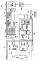
- FIG. 1 is a diagram illustrating an overall configuration of an imaging apparatus according to an embodiment of the present invention.
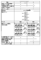
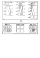
- FIG. 2 is a diagram illustrating (Configuration a) and (Configuration b).
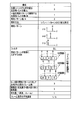
- FIG. 3 is a diagram illustrating (Configuration c).
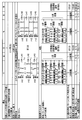
- FIG. 4 is a diagram illustrating (Configuration d) and (Configuration e).
- FIG. 5 is a diagram illustrating (Configuration f).
- FIG. 6 is a diagram showing a modification of one embodiment of the present invention.
- FIG. 1 is a diagram illustrating an overall configuration of an imaging apparatus according to an embodiment of the present invention.
- An imaging apparatus 100 illustrated in FIG. 1 includes an illumination unit 102, an imaging unit 104, an image processing unit 106, a display unit 108, and an imaging mode control unit 110.
- This imaging apparatus 100 basically irradiates the observation target 200 with illumination light from the illumination unit 102, captures light reflected or scattered by the observation target with the imaging unit 104, and is obtained by the imaging unit 104.
- the image signal is processed by the image processing unit 106.
- the imaging apparatus 100 causes the display unit 108 to display an image obtained by the processing of the image processing unit 106.
- the illumination unit 102 irradiates the observation target 200 with illumination light.
- the illumination unit 102 includes an illumination unit 1021 and an illumination switching control unit 1022.
- the illumination unit 1021 is configured to selectively irradiate illumination light of L different light wavelength bands.
- L is 3 or more, for example.
- the illumination unit 1021 as an example includes a light source 1021a, a waveguide 1021b, and a light distribution lens 1021c.
- the light source 1021a is L light sources having different light wavelength bands, and is, for example, a semiconductor laser (LD) or a super luminescent diode (SLD).
- FIG. 1 shows an example in which L is 3, and the three light sources 1021a shown in FIG. 1 respectively radiate R (red), G (green), and B (blue) illumination light.
- the waveguide 1021b is an optical fiber, for example, and is optically coupled to L light sources 1021a.
- the waveguide 1021b combines the illumination light emitted from the light source 1021a and emits it to the light distribution lens 1021c.
- the light distribution lens 1021c is, for example, a plano-concave lens, and shapes the illumination light emitted from the waveguide 1021b so as to have a predetermined light distribution spread angle and irradiates the observation target 200.
- the illumination switching control unit 1022 includes a characteristic information storage unit 1022a, an irradiation pattern setting unit 1022b, a drive pattern generation unit 1022c, and a light source driver 1022d, and illumination light of a predetermined N sets of irradiation patterns is emitted from the light source 1021a.
- the lighting unit 1021 is controlled so as to be irradiated.
- the irradiation pattern is a pattern indicating a combination of light of M light wavelength bands extracted at each timing of times t1, t2,..., TN.
- M is an integer of 2 or more and L or less
- N is an integer of 2 or more.
- the characteristic information storage unit 1022a stores characteristic information of the illumination unit 102 and the imaging unit 104.
- the characteristic information of the illuminating unit 102 includes information on connection terminals between the light source 1021a and the light source driver 1022d, information on the color (or wavelength band) that the light source 1021a can irradiate, and correspondence information between the drive intensity of the light source 1021a and the output of the light source 1021a.
- the characteristic information of the imaging unit 104 is mainly array information of the optical wavelength sensitivity characteristics of the imaging pixels constituting the imaging unit.
- Information indicating the presence / absence of a color filter of the imaging element 1042 For example, information indicating an array.
- the irradiation pattern setting unit 1022b sets N irradiation patterns so that the combinations of illumination light colors are different from each other in accordance with the input of required performance information of the imaging apparatus 100 from the imaging mode control unit 110, and sets the irradiation patterns to the set irradiation patterns. In response, the lighting unit control signal is generated.
- the required performance information is information for determining the performance of the imaging apparatus 100 such as whether the imaging apparatus 100 is set to a high frame rate mode, a high resolution mode, or a high sensitivity mode.
- the drive pattern generation unit 1022c Based on the characteristic information of the illumination unit 102 and the illumination unit control signal, the drive pattern generation unit 1022c outputs a light source driver control signal so that the illumination light of the illumination pattern set by the illumination pattern setting unit 1022b is emitted from the light source 1021a. Generate.
- the light source driver 1022d controls driving of the light source 1021a of the illumination unit 1021 according to the light source driver control signal.
- the illumination unit 102 can extract light in a predetermined M light wavelength bands and irradiate it at a predetermined time.
- the illumination unit 102 irradiates the observation target 200 with illumination light by changing N combinations of light of predetermined M light wavelength bands.
- L is the number of light wavelength bands that can be irradiated by the illumination unit
- M is the number of light wavelength bands to be irradiated in one set of irradiation patterns
- N is the number of irradiation patterns to be repeatedly irradiated.
- the imaging unit 104 captures an observation target and obtains an image signal related to the observation target.
- the imaging unit 104 includes an imaging lens 1041 and an imaging element 1042.
- the imaging lens 1041 is an optical system that images light reflected or scattered by the observation target 200 on the image sensor 1042.
- the image sensor 1042 converts an optical image formed through the imaging lens 1041 into an image signal as an electric signal.
- the imaging element 1042 includes a light receiving element 1042a and a color filter 1042b.
- the light receiving element 1042a is, for example, a photodiode arranged two-dimensionally, and performs photoelectric conversion.
- the color filter 1042b is provided in the light receiving element 1042a so as to correspond to each light receiving element 1042a, and makes an optical image of a specific wavelength band in the light from the observation target 200 incident on the corresponding light receiving element 1042a.
- the image sensor 1042 may not include the color filter 1042b. In this case, the image sensor 1042 does not have color selectivity.
- the imaging apparatus 100 is an observation environment in which only the illumination light from the illumination unit 102 is irradiated onto the observation target 200, that is, in an environment where there is substantially no influence of external light. The performance can be extracted most ideally. Therefore, the imaging apparatus 100 according to the present embodiment is configured to cover, for example, the illumination unit 102, the imaging unit 104, and the observation target 200 in an environment where the influence of external light other than the irradiation light from the illumination unit 102 is suppressed. It is preferable that the external light suppressing member 300 is used.
- the imaging apparatus 100 is suitable for applications such as a microscope apparatus and an endoscope apparatus that often acquire images in an environment that is substantially not affected by external light.
- ⁇ Lw, i ⁇ Fw, i (i 1,2, ..., L) (1)
- the spectrum width of the irradiation light is narrow.
- a laser light source, a super luminescent diode, or the like is preferable as the light source 1021a. If the condition of the expression (1) can be satisfied, the color reproducibility does not deteriorate even if the number M of light wavelength bands in each irradiation pattern increases. Further, high image display performance (resolution / frame rate / SN / color reproducibility, etc.) corresponding to the number M of light wavelength bands can be provided.
- the image processing unit 106 processes the image signal obtained by the imaging unit 104 to generate an image.
- the image processing unit 106 according to the present embodiment performs various processes according to the characteristics of the light source 1021a, the characteristics of the image sensor 1042, and a function request for image processing.
- FIG. 1 shows a typical configuration of the image processing unit 106. 1 includes an A / D converter 1061, a frame memory 1062, a secondary image generation unit 1063, a tertiary image generation unit 1064, a display mode switching unit 1065, an image correction unit 1066, have.
- the A / D converter 1061 samples the image signal obtained by the imaging unit 104 in synchronization with the input timing of the light source driver control signal generated by the drive pattern generation unit 1022c, and the sampled image signal is an image of a digital signal. It is converted into a signal (primary image information).
- the frame memory 1062 stores primary image information obtained by the A / D converter 1061. In the present embodiment, N pieces of primary image information are obtained by performing N times of imaging in accordance with N sets of irradiation patterns.
- the frame memory 1062 stores the N pieces of primary image information.
- the secondary image generation unit 1063 performs processing according to the light source driver control signal generated by the drive pattern generation unit 1022c on the N pieces of primary image information stored in the frame memory 1062 to obtain the secondary image information.
- the tertiary image generation unit 1064 processes the secondary image information as necessary to generate tertiary image information. Details of processing of the secondary image generation unit 1063 and the tertiary image generation unit 1064 will be described later.
- the display mode switching unit 1065 generates image information to be output to the image correction unit 1066 according to the display mode of the display unit 108 by using the secondary image information generated by the secondary image generation unit 1063 and the tertiary image generation unit 1064. Switch to the tertiary image information.
- the image correction unit 1066 performs correction processing necessary for display and recording on the secondary image information or the tertiary image information. This correction processing is, for example, correction of color temperature, correction of gamma characteristics, enhancement processing or suppression processing of a specific light wavelength (color component in image information).
- the display unit 108 displays a display frame based on at least one of the secondary image information and the tertiary image information corrected by the image correction unit 1066. That is, the display unit 108 displays the display frame based on the secondary image information and the display frame based on the tertiary image information independently, or displays based on the display frame based on the secondary image information and the tertiary image information. Display the frame at the same time. Which display is performed is determined by the display mode. The display mode is set by a user, for example.
- the imaging mode control unit 110 is a CPU, for example, and is a synchronization signal to each of the imaging element 1042 of the imaging unit 104, the drive pattern generation unit 1022c of the illumination unit 102, the secondary image generation unit 1063 of the image processing unit 106, and the display unit 108. To control these blocks synchronously.
- the imaging mode control unit 110 also inputs required performance information to the irradiation pattern setting unit 1022b. The required performance information is set by a user, for example.
- the imaging apparatus 100 basically has the configuration shown in FIG. However, the imaging apparatus 100 has six configurations, that is, (configuration a), (configuration b), and (configuration c) depending on how to set the irradiation pattern, whether or not the color filter 1042b is combined with the light receiving element 1042a, and the type of the color filter 1042b. ), (Configuration d), (configuration e), and (configuration f), and perform different operations according to the respective configurations.
- an operation corresponding to each configuration of the imaging apparatus 100 will be described.
- the required number of primary images are acquired from the start of the illumination operation, and the time taken to generate the final display frame image (secondary image or tertiary image) is adjusted.
- the average frame display speed is fast means that the display delay with respect to the moving observation object is small, that is, the movement of the observation object can be displayed naturally (smoothly) at a high frame rate.
- the average speed of the frame display is slow means that the display delay with respect to the moving observation target is large, that is, the time interval until the display is switched at a low frame rate, and the movement of the observation target is smooth. It means that it cannot be displayed.
- (Configuration a) and (Configuration b) are configurations using an irradiation pattern corresponding to the white broadband illumination method.
- (Configuration a) and (Configuration b) differ in the type of color filter 1042b. That is, the color filter 1042b in (Configuration a) is a primary color filter, and the color filter 1042b in (Configuration b) is a complementary color filter.
- the “primary color filter” in the present embodiment is one of the L light wavelength bands that can be irradiated by the illumination unit 1021, and is close to this light wavelength band on one light wavelength band or on the wavelength axis.
- a filter configured by two-dimensionally arranging filter elements capable of transmitting the continuous wavelength region in accordance with a continuous wavelength region including a plurality of optical wavelength bands. It is.
- the primary color filter of the present embodiment includes a filter element capable of transmitting R illumination light of incident light, and the incident light.
- the filter element is configured by two-dimensionally arranging a filter element that can transmit the G illumination light and a filter element that can transmit the B illumination light of the incident light.
- the primary color filter of the embodiment has a configuration in which four types of filter elements that can transmit only one of the incident lights R1, R2, G, and B of the incident light are two-dimensionally arranged.
- a filter element that can transmit only light in a wavelength range including wavelengths of R1 and R2 that are close to each other on the wavelength axis in incident light, and only G illumination light in incident light.
- a filter element configured by two-dimensionally arranging a filter element that can transmit only B illumination light of incident light.
- the “complementary color filter” in the present embodiment refers to a corresponding one of the light wavelength bands of L light wavelength bands that can be irradiated by the illumination unit 1021 or the light wavelength on the wavelength axis.
- filter elements capable of transmitting light obtained by subtracting the wavelength region are arranged two-dimensionally in accordance with the position of the light receiving element. It is the filter comprised by these.
- the complementary color filter of this embodiment includes a filter element capable of transmitting light obtained by subtracting R illumination light from incident light, and incident light.
- a filter element configured by two-dimensionally arranging a filter element capable of transmitting light obtained by subtracting G illumination light from G and a filter element capable of transmitting light obtained by subtracting B illumination light from incident light. is there.
- the illumination unit 1021 can irradiate illumination light of four colors R1, R2, G, and B
- the complementary color filter of the present embodiment receives each of R1, R2, G, and B of the incident light.
- Four types of filter elements that can transmit light obtained by subtracting only one of the light may be arranged in a two-dimensional manner, but as a modification, the incident light is close on the wavelength axis.
- a filter element capable of transmitting light in a wavelength range excluding light in a wavelength range including wavelengths of R1 and R2, a filter element capable of transmitting light obtained by subtracting G illumination light from incident light, and incident light is also included.
- a lighting unit control signal is generated to be illuminated.
- the drive pattern generation unit 1022c generates a light source driver control signal according to the illumination unit control signal and the characteristic information stored in the characteristic information storage unit 1022a.
- the light source driver 1022d drives the light source 1021a according to the light source driver control signal.
- the imaging unit 104 performs imaging in synchronization with illumination of the observation target by the illumination unit 102. Since the color filter 1042b of (Configuration a) is a primary color filter, each filter element transmits only illumination light in the corresponding optical wavelength band. That is, the R filter element transmits only the R illumination light. Similarly, the G filter element transmits only the G illumination light, and the B filter element transmits only the B illumination light.
- the A / D converter 1061 samples the image signal from each light receiving element 1042a of the imaging unit 104, and converts the sampled image signal into primary image information as a digital signal. To be stored in the frame memory 1062.
- primary image information necessary for color imaging that is, primary image information including all three RGB components is stored in the frame memory 1062 at each illumination light irradiation timing.
- the secondary image generation unit 1063 uses the light source driver control signal to irradiate the illumination pattern (which illumination light of L light wavelength bands is irradiated at each timing) and the presence / absence and type (primary color) of the color filter 1042b. Which of the filter and the complementary color filter is identified, and image processing for color imaging is performed on the primary image information according to the identification result.
- the secondary image generation unit 1063 of (Configuration a) synchronizes (three-plate) primary image information including R information, G information, and B information as color imaging processing. Each pixel performs processing to generate secondary image information having R information, G information, and B information.
- the display mode switching unit 1065 After the image processing by the secondary image generation unit 1063, the display mode switching unit 1065 outputs the secondary image information generated by the secondary image generation unit 1063 to the image correction unit 1066.
- the image correction unit 1066 performs correction processing necessary for display on the display unit 108 on the input secondary image information, and outputs it to the display unit 108. In response to this, the display unit 108 displays a color image.
- illumination light of one light wavelength band is incident on one light receiving element 1042a at each illumination light irradiation timing.
- the light reception amount per pixel for each frame in (Configuration a) is equal to the light reception amount in one light wavelength band.
- the resolution of (configuration a) is one pixel.
- (Configuration a) an image is generated at each irradiation pattern switching timing. That is, the image extraction time of (Configuration a) matches the irradiation pattern switching interval, and the average frame display speed matches the irradiation pattern switching speed.
- the average speed of frame display of (configuration a) is set as a reference value 1. This is for comparison with other configurations.
- each filter element transmits only the illumination light of the complementary color in the corresponding light wavelength band, that is, the illumination light obtained by subtracting the corresponding illumination light. That is, the filter element of R's complementary color (R ⁇ (bar)) transmits only R ⁇ illumination light, that is, G and B illumination light. Similarly, the G complementary color (G- (bar)) filter element transmits only G-light, that is, R and B illumination light, and B complementary color (B- (bar)). The filter element transmits only B-illumination light, that is, R and G illumination light.
- the secondary image generation unit 1063 of (Configuration b) performs R-information (that is, G + B), G-information (that is, R + B), B-information (that is acquired almost simultaneously) as color imaging processing ( That is, the difference between the information obtained by adding all R + G) and the R-, G-, B-independent information at a predetermined ratio, and the image corresponding to the R information, the G information, and the B information.
- Secondary image information is generated by performing a process of synchronizing information (three plates).
- the display mode switching unit 1065 After the image processing by the secondary image generation unit 1063, the display mode switching unit 1065 outputs the secondary image information generated by the secondary image generation unit 1063 to the image correction unit 1066.
- the image correction unit 1066 performs correction processing necessary for display on the display unit 108 on the input secondary image information, and outputs it to the display unit 108. In response to this, the display unit 108 displays a color image.
- one piece of secondary image information is generated from one piece of primary image information. Accordingly, the resolution of (configuration b) is one pixel, as in (configuration a).
- (Configuration b) acquisition of the number of primary image information and generation of secondary image information necessary for generating an image are performed within the irradiation pattern switching interval. That is, the image extraction time of (Configuration b) matches the irradiation pattern switching interval, and the average frame display speed matches the irradiation pattern switching speed.
- (Configuration b) is a configuration used in applications with higher sensitivity than (Configuration a).
- (Configuration b) a process for converting a complementary color signal into a primary color signal is required, and therefore in terms of color reproduction, it is inferior to (Configuration a).
- (Configuration c) is a configuration in the case of using an irradiation pattern corresponding to the field sequential illumination method.
- the illumination unit control signal is generated so that the illumination light B is emitted.
- the imaging device 1042 of the imaging unit 104 of (configuration c) does not have the color filter 1042b and has no color selectivity. Therefore, the illumination light is received by the light receiving element 1042a as it is without being absorbed by the color filter. That is, at the timing when the R illumination light is irradiated, the R illumination light is received by the light receiving element 1042a. Similarly, at the timing when the G illumination light is irradiated, the G illumination light is received by the light receiving element 1042a, and at the timing when the B illumination light is irradiated, the B illumination light is received by the light receiving element 1042a.
- the secondary image generation unit 1063 of (configuration c) performs the same synchronization processing as that of (configuration a). However, in the case of (Configuration c), primary image information necessary for color imaging is obtained by switching illumination light three times. Therefore, the secondary image generation unit 1063 of (Configuration c) identifies the illumination light switching timing based on the light source driver control signal, whereby the primary image information 1 of R, the primary image information 2 of G, Secondary image information is generated by performing a process of synchronizing (three plates) when the primary image information 3 of B is complete.
- the display mode switching unit 1065 After the image processing by the secondary image generation unit 1063, the display mode switching unit 1065 outputs the secondary image information generated by the secondary image generation unit 1063 to the image correction unit 1066.
- the image correction unit 1066 performs correction processing necessary for display on the display unit 108 on the input secondary image information, and outputs it to the display unit 108. In response to this, the display unit 108 displays a color image.
- illumination light of one light wavelength band is incident on one light receiving element 1042a at every illumination light irradiation timing.
- one piece of secondary image information is generated using three pieces of primary image information, it can be said that one light receiving element 1042a corresponds to L pixels. Therefore, the amount of light per pixel of (configuration c) is 1 / L times (1/3 times in the example) of (configuration a), and the amount of light per pixel in (configuration c) is (configuration a). N / L times (1x in the example).
- the spatial resolution is approximately L times (3 times in the example) compared to (Configuration a).
- the image extraction time of (configuration c) is N times (3 times in the example) the irradiation pattern switching interval, and the average frame display speed is 1 / N times (in the example, the irradiation pattern switching speed). 1/3 times).
- (Configuration c) is a configuration that is used for higher resolution applications than (Configuration a).
- the average speed of frame display is inferior to (configuration a).
- the imaging device 100 of (Configuration d) and (Configuration e) will be described with reference to FIG. (Configuration d) and (Configuration e) described below are “a plurality of light sources that extract not only one color but also a predetermined plurality of colors using a light source that can irradiate a plurality of colors to an observation target.
- the irradiation pattern is set, and irradiation is performed while switching a plurality of irradiation patterns having different combinations of illumination colors ”.
- the display performance is improved by switching the irradiation pattern.
- (Configuration d) is an imaging apparatus in which N sets of irradiation patterns for extracting and irradiating illumination light of M light wavelength bands from illumination light of L light wavelength bands are prepared, and the N irradiation patterns are sequentially switched. 100, the image sensor 1042 does not include the color filter 1042b.
- the imaging unit 104 does not include the color filter 1042b. Therefore, the illumination light is received by the light receiving element 1042a as it is without being absorbed by the color filter. That is, at the timing when the G and B illumination lights are irradiated, the G and B illumination lights are received by the light receiving element 1042a. This is the same as when the R ⁇ illumination light is received by the light receiving element 1042a. Similarly, at the timing when the R and B illumination lights are irradiated, the R and B illumination lights are received by the light receiving element 1042a. This is the same as when the G ⁇ illumination light is received by the light receiving element 1042a. Further, at the timing when the R and G illumination lights are irradiated, the R and G illumination lights are received by the light receiving element 1042a. This is the same as when the B ⁇ illumination light is received by the light receiving element 1042a.
- the secondary image generation unit 1063 of (configuration d) performs image processing that combines the image processing of (configuration b) and (configuration c). That is, the secondary image generation unit 1063 generates secondary image information from the three pieces of primary image information as in (Configuration c). However, in the case of (Configuration d), primary image information 1, 2, and 3 including complementary color information is obtained. Therefore, the secondary image generation unit 1063 of (configuration d) performs primary image information 1, 2 including R-information, G-information, and B-information in the same manner as (configuration b). 3 and the R-, G-, and B-individual information at a predetermined ratio, and the R information, the G information, and the image information corresponding to the B information.
- the secondary image information is generated by performing a process of synchronizing (three plates).
- the display mode switching unit 1065 After the image processing by the secondary image generation unit 1063, the display mode switching unit 1065 outputs the secondary image information generated by the secondary image generation unit 1063 to the image correction unit 1066.
- the image correction unit 1066 performs correction processing necessary for display on the display unit 108 on the input secondary image information, and outputs it to the display unit 108. In response to this, the display unit 108 displays a color image.
- illumination light of two light wavelength bands is incident on one light receiving element 1042a at each illumination light switching timing. Accordingly, when viewed as one frame, the amount of light per pixel of (configuration d) is twice that of (configuration a). More generally, illumination light of M light wavelength bands enters one light receiving element 1042a at each illumination light switching timing. Accordingly, the light amount per pixel of (Configuration d) is M times that of (Configuration a) on average, but since one light receiving element 1042a corresponds to L pixels, the light amount per pixel is M. / L times, and the amount of light per pixel in one frame is N ⁇ M / L times. In (configuration d), since one light receiving element 1042a functions as L pixels, the spatial resolution is L times that of (configuration a).
- the image extraction time of (Configuration d) is three times the irradiation pattern switching interval, and the average frame display speed is 1/3 times the irradiation pattern switching speed.
- the image extraction time of (Configuration d) is N times the irradiation pattern switching interval, and the average frame display speed is 1 / N times the irradiation pattern switching speed.
- (Configuration d) is a configuration that is used in applications with higher sensitivity and higher resolution than (Configuration a).
- the average speed of frame display is inferior to (Configuration a).
- (Configuration d) has an advantage of higher sensitivity than (Configuration c) while having a resolution equivalent to that of (Configuration c) having a high resolution.
- (Configuration e) is an imaging apparatus that prepares N sets of irradiation patterns for extracting and irradiating illumination light of M light wavelength bands from illumination light of L light wavelength bands, and sequentially switches the N irradiation patterns.
- the image sensor 1042 has a primary color filter.
- the imaging unit 104 has a primary color filter. Accordingly, only the illumination light corresponding to each filter element is received by the light receiving element 1042a. That is, at the timing when the G and B illumination lights are irradiated, the R filter element does not transmit the illumination light, the G filter element transmits only the G illumination light, and the B filter element transmits the B illumination light. Permeate only. At the timing when the R and B illumination lights are irradiated, the R filter element transmits only the R illumination light, the G filter element does not transmit the illumination light, and the B filter element transmits only the B illumination light. Make it transparent.
- the R filter element transmits only the R illumination light
- the G filter element transmits only the G illumination light
- the B filter element transmits the illumination light. I won't let you. In this way, in (Configuration e), primary color information corresponding to two sets of different color components is obtained at each timing.
- secondary image generation unit 1063 generates secondary image information from primary color information obtained at two successive timings. That is, the secondary image generation unit 1063 performs secondary processing by performing a process of synthesizing (three-plate) the G information and B information obtained at timing 1 and the R information obtained at timing 2. Generate image information. Further, the secondary image generation unit 1063 performs secondary processing by performing a process of synchronizing (three plates) the B information obtained at timing 2 with the R information and G information obtained at timing 3. Generate image information.
- the display mode switching unit 1065 After the image processing by the secondary image generation unit 1063, the display mode switching unit 1065 outputs the secondary image information generated by the secondary image generation unit 1063 to the image correction unit 1066.
- the image correction unit 1066 performs correction processing necessary for display on the display unit 108 on the input secondary image information, and outputs it to the display unit 108. In response to this, the display unit 108 displays a color image.
- illumination light of one light wavelength band is incident on one light receiving element 1042a at each illumination light switching timing, but when viewed in terms of the amount of light per pixel of one frame. It becomes smaller than (Configuration a).
- the spatial resolution is the same as that in (Configuration a).
- the image extraction time of (Configuration e) is twice as long as the irradiation pattern switching interval, and the average frame display speed is 1 ⁇ 2 times the irradiation pattern switching speed.
- the image extraction time of (configuration e) is (N-1) times the irradiation pattern switching interval, and the average frame display speed is 1 / (N-1) of the irradiation pattern switching speed. ) Doubled.
- (Configuration e) is a configuration used in a higher frame rate mode than (Configuration c).
- the settings of L, M, and N are not limited to those shown in the examples.
- the number of irradiation patterns N 4, and one of the four irradiation patterns may be irradiated with all of the illumination light in the three light wavelength bands.
- the imaging device 100 having the (configuration f) will be described with reference to FIG. (Configuration f) described below is similar to (Configuration d) and (Configuration e). “Using a light source that can irradiate a plurality of colors to an observation target, not only one color but also a predetermined plurality of colors. A plurality of irradiation patterns for extracting and irradiating light are set, and irradiation is performed while switching a plurality of irradiation patterns having different combinations of illumination colors. ”
- the image sensor 1042 has a complementary color filter. It is a configuration.
- the imaging unit 104 of (Configuration f1) to (Configuration f6) has a complementary color filter. Therefore, only the illumination light obtained by subtracting the illumination light corresponding to each filter element is received by the light receiving element 1042a. That is, at the timing when the G and B illumination lights are irradiated, the R ⁇ filter element transmits the G and B illumination lights as they are, the G ⁇ filter element transmits only the B illumination light, and the B ⁇ The filter element transmits only G illumination light. At the timing when the R and B illumination lights are applied, the R ⁇ filter element transmits only the B illumination light, the G ⁇ filter element transmits the R and B illumination light as they are, and the B ⁇ filter element. Transmits only R illumination light. At the timing when the R and G illumination lights are applied, the R ⁇ filter element transmits only the G illumination light, the G ⁇ filter element transmits only the R illumination light, and the B ⁇ filter element remains as it is. Transmits R and B illumination light.
- the secondary image generation unit 1063 of (configuration f1) recognizes the signal obtained from the light receiving element 1042a corresponding to the R ⁇ filter element as an R complementary color signal, and uses the G ⁇ filter.
- a signal obtained from the light receiving element 1042a corresponding to the element is recognized as a B primary color signal
- a signal obtained from the light receiving element 1042a corresponding to the B ⁇ filter element is recognized as a G primary color signal, and an image including these information Processing for generating secondary image information 1 using the information as primary image information 1 is performed.
- the secondary image generation unit 1063 recognizes the signal obtained from the light receiving element 1042a corresponding to the R ⁇ filter element as a B primary color signal and corresponds to the G ⁇ filter element.
- the signal obtained from the received light receiving element 1042a is recognized as a G complementary color signal
- the signal obtained from the light receiving element 1042a corresponding to the B-filter is recognized as an R primary color signal
- image information including these information is first-order. Processing for generating secondary image information 2 as image information 2 is performed.
- a signal obtained from the light receiving element 1042a corresponding to the R ⁇ filter element is recognized as a G primary color signal
- a signal obtained from the light receiving element 1042a corresponding to the G ⁇ filter element is R Is recognized as a primary color signal
- a signal obtained from the light receiving element 1042a corresponding to the B ⁇ filter element is recognized as a complementary color signal for B, and image information including these information is used as primary image information 3 for secondary image information 3.
- the secondary image generation unit 1063 of (Configuration f1) repeats switching of the irradiation pattern, and converts the RGB primary color signals obtained by light irradiation with the previous or second previous irradiation pattern in time.
- the display mode switching unit 1065 After the image processing by the secondary image generation unit 1063, the display mode switching unit 1065 outputs the secondary image information generated by the secondary image generation unit 1063 to the image correction unit 1066.
- the image correction unit 1066 performs correction processing necessary for display on the display unit 108 on the input secondary image information, and outputs it to the display unit 108. In response to this, the display unit 108 displays a color image.
- (Configuration f1) is thus configured to be used in a mode with higher sensitivity than (Configuration a) and a higher frame rate than (Configuration c).
- (Configuration f2) is the same as (Configuration f1) until the secondary image information is obtained, and further differs in that tertiary image information is generated as a display image. That is, the secondary image generation unit 1063 of (configuration f2) inputs the latest three pieces of secondary image information 1, 2, and 3 to the tertiary image generation unit 1064. The tertiary image generation unit 1064 combines the secondary image information 1, 2, and 3 to generate one tertiary image information including information on all light wavelength bands of RGB. The display mode switching unit 1065 outputs the tertiary image information generated by the tertiary image generation unit 1064 to the image correction unit 1066.
- the image correction unit 1066 performs correction processing necessary for display on the display unit 108 on the input tertiary image information, and outputs it to the display unit 108. In response to this, the display unit 108 displays a color image.
- the primary image information 1, 2, 3 and the secondary image information 1, 2, 3 are used to generate tertiary image information including information on all light wavelength bands of RGB. May be.
- one piece of secondary image information is generated using three pieces of primary image information in the same manner as (configuration c). That is, also in (Configuration f2), since one light receiving element functions as L pixels, the spatial resolution is L times that of (Configuration a). On the other hand, the average frame display speed is 1 / N times that of (Configuration a). Others are the same as (Configuration f1).
- (Configuration f3) is the same as (Configuration f2) until the generation of the tertiary image information.
- the display mode switching unit 1065 of (Configuration f3) includes the secondary image information generated by the secondary image generation unit 1063 and the tertiary image information generated by the tertiary image generation unit 1064. Is selected as the final display frame and output to the image correction unit 1066.
- the image correction unit 1066 performs correction processing necessary for display on the display unit 108 on the input image information and outputs the processed image information to the display unit 108. In response to this, the display unit 108 displays a color image.
- the most recent secondary image information is used to generate the tertiary image information. Therefore, selection of image information by the display mode switching unit 1065 is performed from the third frame onward.
- selection of image information by the display mode switching unit 1065 is performed from the third frame onward.
- an example in which either an image based on secondary image information or an image based on tertiary image information is displayed has been described, but both images may be displayed in parallel.
- the image display mode corresponding to (configuration f1) and the image display mode corresponding to (configuration f2) can be switched as necessary. That is, when high resolution is desired, it can be displayed with the image characteristics of (Configuration f2) (high resolution but low frame rate), and when it is desired to smoothly display the movement of a fast observation target, (Configuration f1) It is possible to display with image characteristics (not high resolution but high frame rate). In this way, it is possible to select which of the resolution and the frame rate has priority according to the image display mode, or to simultaneously display both using both modes.
- (Configuration f4) is the same as (Configuration f1) until the acquisition of the primary image information.
- a process of generating secondary image information 1 by recognizing it as a primary color signal and using image information including such information as primary image information 1 is performed.
- the obtained signal is recognized as a complementary color signal of B, and processing for generating secondary image information 2 using image information including these pieces of information as primary image information 2 is performed.
- the obtained signal is recognized as an R complementary color signal, and the image information including these pieces of information is used as primary image information 3 to generate secondary image information 3.
- the primary image information obtained in (Configuration f4) has either primary color information of the RGB light wavelength band or complementary color information of the RGB light wavelength band. Therefore, the secondary image information 1, 2, and 3 can be sent to the image correction unit 1066 and further to the display unit 108 without passing through the tertiary image generation unit 1064. Note that in order to simplify image processing, when image processing is performed using only primary color signals, the secondary image information 3 may not be used to generate a final image. In the description relating to the effect of (Configuration f4) described below, description of the effect in the case where the secondary image information 3 is not used for generating the final image is omitted.
- (Configuration f5) is the same as (Configuration f4) until generation of secondary image information, and further differs in that tertiary image information is generated as a display image. That is, the secondary image generation unit 1063 of (configuration f5) inputs the latest three pieces of secondary image information 1, 2, and 3 to the tertiary image generation unit 1064. The tertiary image generation unit 1064 combines the secondary image information 1, 2, and 3 to generate one tertiary image information including information on all light wavelength bands of RGB.
- the display mode switching unit 1065 outputs the tertiary image information generated by the tertiary image generation unit 1064 to the image correction unit 1066.
- the image correction unit 1066 performs correction processing necessary for display on the display unit 108 on the input tertiary image information, and outputs it to the display unit 108. In response to this, the display unit 108 displays a color image.
- (Configuration f6) is the same as (Configuration f5) until the generation of the tertiary image information.
- the display mode switching unit 1065 in (Configuration f6) includes the secondary image information generated by the secondary image generation unit 1063 and the tertiary image information generated by the tertiary image generation unit 1064. Is selected as the final image and output to the image correction unit 1066.
- the image correction unit 1066 performs correction processing necessary for display on the display unit 108 on the input image information and outputs the processed image information to the display unit 108. In response to this, the display unit 108 displays a color image.
- the most recent secondary image information is used to generate the tertiary image information. Therefore, selection of image information by the display mode switching unit 1065 is performed from the third frame onward.
- selection of image information by the display mode switching unit 1065 is performed from the third frame onward.
- an example in which either an image based on secondary image information or an image based on tertiary image information is displayed has been described, but both images may be displayed in parallel.
- the image display mode corresponding to (configuration f4) and the image display mode corresponding to (configuration f5) can be switched as necessary. That is, when high resolution is desired, it can be displayed with the image characteristics of (configuration f5) (high resolution but low frame rate), and when it is desired to smoothly display the movement of a fast observation target, (configuration f4). It is possible to display with image characteristics (not high resolution but high frame rate). In this way, it is possible to select which of the resolution and the frame rate has priority according to the image display mode, or to simultaneously display both using both modes.
- the complementary color information in the primary image information obtained by (Configuration f1) is set to 1/2 of the total signal received by the three light receiving elements 1042a in the full band (RGB) and the timing 1, 2, 3 can be converted into primary color information by taking a difference from the complementary color signal acquired in each of the three.
- the irradiation pattern is set according to the characteristics of the imaging unit 104 and the performance required for the imaging device 100, thereby preventing the size of the device from being increased and the basics of the imaging device. Specific performance can be selected as needed.
- Generate unit control signals That is, the pattern A2 shown in (Configuration d), (Configuration e), and (Configuration f) is divided into a pattern B2 and a pattern B4.
- the irradiation patterns D0 to D4 shown in the upper part of FIG. 6 are obtained by adding an irradiation pattern D0 for irradiating all of RGBO illumination light to the irradiation patterns B1 to B4.
- the illumination unit control signal is generated so that the R and O illumination lights are emitted as the pattern D4.
- the lower part of FIG. 6 shows the arrangement of the filters.
- the four primary color filters shown in the lower part of FIG. 6 are two-dimensionally arranged with filter elements capable of transmitting a corresponding one of the four light wavelength band incident lights that can be irradiated by the illumination unit 1021. It is a filter constituted by this. That is, the primary color filter includes a filter element capable of transmitting R illumination light of incident light, a filter element capable of transmitting G illumination light of incident light, and B illumination light of incident light.
- the filter element is configured by two-dimensionally arranging a filter element that can transmit light and a filter element that can transmit O illumination light of incident light.
- the filter 6 has a two-dimensional filter element that can transmit light obtained by subtracting one corresponding light from light of L light wavelength bands that can be irradiated by the illumination unit 1021. It is the filter comprised by arrange
- the filter is configured by two-dimensionally arranging a filter element capable of transmitting light obtained by subtracting illumination light and a filter element capable of transmitting light obtained by subtracting O illumination light from incident light.
- each of the (configuration a) to (configuration c) (1-band / pattern switching illumination), (configuration d), and (configuration f) (multi-band / pattern switching illumination) is used as the illumination pattern.
- the lighting pattern switching setting is fixed for the case (that is, M is fixed), the image processing algorithm of the corresponding image processing means is shown, and the image characteristics that can be generated by this algorithm and the switching variations thereof are described
- the number L of light wavelength bands that the illumination unit can irradiate need not be the same as the number of primary color filters or complementary color filters.
- the number of primary color filter elements shown in FIG. 6 may be reduced by one to provide three types of filter arrangements: RO filter, G filter, and B filter. (The RO filter transmits only R and O light and blocks G and B. The G filter transmits only G. The B filter transmits only B).
- the number of complementary color filter elements shown in FIG. 6 may be reduced by one to form three types of filter arrangements: RO-filter, G-filter, and B-filter (the RO-filter blocks R and O light). , G and B are transmitted. The G-filter blocks only G. The B-filter blocks only B).
- the imaging device of the imaging unit is configured as follows: “When the filter array combined with the light receiving element array is a monochrome filter, a complementary color filter, and a primary color The case where it is a filter ”has been described, but the case where the image sensor is configured so that the optical wavelength sensitivity characteristic is in a predetermined arrangement without being combined with the filter is included (that is, different light is applied to each pixel of the image sensor). Provide wavelength sensitivity characteristics).
- “photodetection element that does not limit the sensitivity characteristic with respect to the light wavelength” when “light receiving element” is used, and “sensitivity characteristic with respect to the light wavelength” when “imaging pixel” is described.
- photodetection element including is described as “imaging element”, it means “an assembly of an array of imaging pixels (light detection elements including sensitivity characteristics with respect to the light wavelength)”.
Landscapes
- Physics & Mathematics (AREA)
- Health & Medical Sciences (AREA)
- Life Sciences & Earth Sciences (AREA)
- Engineering & Computer Science (AREA)
- Surgery (AREA)
- Optics & Photonics (AREA)
- General Physics & Mathematics (AREA)
- Multimedia (AREA)
- Nuclear Medicine, Radiotherapy & Molecular Imaging (AREA)
- Veterinary Medicine (AREA)
- Radiology & Medical Imaging (AREA)
- Biophysics (AREA)
- Biomedical Technology (AREA)
- Heart & Thoracic Surgery (AREA)
- Medical Informatics (AREA)
- Molecular Biology (AREA)
- Animal Behavior & Ethology (AREA)
- General Health & Medical Sciences (AREA)
- Public Health (AREA)
- Pathology (AREA)
- Signal Processing (AREA)
- Astronomy & Astrophysics (AREA)
- Chemical & Material Sciences (AREA)
- Analytical Chemistry (AREA)
- Computer Vision & Pattern Recognition (AREA)
- Endoscopes (AREA)
- Color Television Image Signal Generators (AREA)
- Closed-Circuit Television Systems (AREA)
- Studio Devices (AREA)
- Instruments For Viewing The Inside Of Hollow Bodies (AREA)
- Microscoopes, Condenser (AREA)
Priority Applications (3)
| Application Number | Priority Date | Filing Date | Title |
|---|---|---|---|
| CN201580008463.5A CN105981377B (zh) | 2014-02-19 | 2015-01-23 | 摄像装置、内窥镜装置以及显微镜装置 |
| DE112015000863.2T DE112015000863T5 (de) | 2014-02-19 | 2015-01-23 | Abbildungsvorrichtung, Endoskopvorrichtung und Mikroskopvorrichtung |
| US15/238,341 US10419693B2 (en) | 2014-02-19 | 2016-08-16 | Imaging apparatus, endoscope apparatus, and microscope apparatus |
Applications Claiming Priority (2)
| Application Number | Priority Date | Filing Date | Title |
|---|---|---|---|
| JP2014029925A JP6460631B2 (ja) | 2014-02-19 | 2014-02-19 | 撮像装置、内視鏡装置及び顕微鏡装置 |
| JP2014-029925 | 2014-02-19 |
Related Child Applications (1)
| Application Number | Title | Priority Date | Filing Date |
|---|---|---|---|
| US15/238,341 Continuation US10419693B2 (en) | 2014-02-19 | 2016-08-16 | Imaging apparatus, endoscope apparatus, and microscope apparatus |
Publications (1)
| Publication Number | Publication Date |
|---|---|
| WO2015125553A1 true WO2015125553A1 (ja) | 2015-08-27 |
Family
ID=53878067
Family Applications (1)
| Application Number | Title | Priority Date | Filing Date |
|---|---|---|---|
| PCT/JP2015/051810 Ceased WO2015125553A1 (ja) | 2014-02-19 | 2015-01-23 | 撮像装置、内視鏡装置及び顕微鏡装置 |
Country Status (5)
| Country | Link |
|---|---|
| US (1) | US10419693B2 (enExample) |
| JP (1) | JP6460631B2 (enExample) |
| CN (1) | CN105981377B (enExample) |
| DE (1) | DE112015000863T5 (enExample) |
| WO (1) | WO2015125553A1 (enExample) |
Cited By (3)
| Publication number | Priority date | Publication date | Assignee | Title |
|---|---|---|---|---|
| CN108780585A (zh) * | 2016-04-01 | 2018-11-09 | 英特尔公司 | 用于光线追踪架构的采样模式生成的方法和装置 |
| US20190046020A1 (en) * | 2015-10-30 | 2019-02-14 | Sony Corporation | Information processing apparatus, information processing method, and endoscope system |
| WO2021048683A1 (ja) * | 2019-09-13 | 2021-03-18 | 株式会社半導体エネルギー研究所 | 撮像装置、撮像モジュール、電子機器及び撮像方法 |
Families Citing this family (15)
| Publication number | Priority date | Publication date | Assignee | Title |
|---|---|---|---|---|
| WO2014144989A1 (en) | 2013-03-15 | 2014-09-18 | Ostendo Technologies, Inc. | 3d light field displays and methods with improved viewing angle depth and resolution |
| JP6460631B2 (ja) * | 2014-02-19 | 2019-01-30 | オリンパス株式会社 | 撮像装置、内視鏡装置及び顕微鏡装置 |
| JP6005303B2 (ja) * | 2014-04-08 | 2016-10-12 | オリンパス株式会社 | 蛍光観察内視鏡システム |
| US9977232B2 (en) * | 2015-01-29 | 2018-05-22 | Fujifilm Corporation | Light source device for endoscope, endoscope system, and method for operating light source device for endoscope |
| WO2017110492A1 (ja) * | 2015-12-24 | 2017-06-29 | オリンパス株式会社 | 撮像システム及び画像処理装置 |
| US9946638B1 (en) * | 2016-03-30 | 2018-04-17 | Open Text Corporation | System and method for end to end performance response time measurement based on graphic recognition |
| JPWO2017175391A1 (ja) * | 2016-04-08 | 2019-03-28 | オリンパス株式会社 | 照明装置およびこれを備えた内視鏡 |
| KR101783142B1 (ko) | 2016-06-02 | 2017-09-28 | 연세대학교 산학협력단 | 색과 편광 패턴을 이용한 영상 시스템 |
| DE112018005061T5 (de) * | 2017-09-12 | 2020-06-18 | Sony Corporation | Informationsverarbeitungsvorrichtung, informationsverarbeitungsverfahren, programm und beleuchtungssystem |
| TWI694727B (zh) * | 2018-03-20 | 2020-05-21 | 台達電子工業股份有限公司 | 投影顯示設備及控制方法 |
| JP7317485B2 (ja) * | 2018-10-17 | 2023-07-31 | シャープ株式会社 | 画像形成装置 |
| US10949706B2 (en) * | 2019-01-16 | 2021-03-16 | Microsoft Technology Licensing, Llc | Finding complementary digital images using a conditional generative adversarial network |
| EP3691258B1 (en) * | 2019-01-29 | 2021-09-15 | Fondation de L'institut de Recherche Idiap | System and method for acquiring images |
| US12108163B2 (en) * | 2020-01-03 | 2024-10-01 | JEJU National University Industry—Academic Cooperation Foundation | Device of photographing ultra-high-speed sequential images |
| CN120547311A (zh) * | 2024-02-23 | 2025-08-26 | 台达电子工业股份有限公司 | 投影显示装置 |
Citations (3)
| Publication number | Priority date | Publication date | Assignee | Title |
|---|---|---|---|---|
| JP2010042133A (ja) * | 2008-08-12 | 2010-02-25 | Fujifilm Corp | 画像取得方法および装置 |
| JP2013248319A (ja) * | 2012-06-04 | 2013-12-12 | Olympus Corp | 蛍光内視鏡装置 |
| JP2013255655A (ja) * | 2012-06-12 | 2013-12-26 | Olympus Corp | 撮像装置、顕微鏡装置、内視鏡装置 |
Family Cites Families (7)
| Publication number | Priority date | Publication date | Assignee | Title |
|---|---|---|---|---|
| JPS63227293A (ja) | 1987-03-17 | 1988-09-21 | Olympus Optical Co Ltd | 面順次カラ−撮像装置 |
| JP2001299676A (ja) * | 2000-04-25 | 2001-10-30 | Fuji Photo Film Co Ltd | センチネルリンパ節検出方法および検出システム |
| US7773802B2 (en) * | 2002-07-26 | 2010-08-10 | Olympus Corporation | Image processing system with multiple imaging modes |
| JP5449816B2 (ja) * | 2009-03-26 | 2014-03-19 | オリンパス株式会社 | 画像処理装置、画像処理プログラムおよび画像処理装置の作動方法 |
| JP2013223043A (ja) * | 2012-04-13 | 2013-10-28 | Toshiba Corp | 受光装置および伝送システム |
| AU2013299770B2 (en) * | 2012-08-07 | 2017-07-20 | University Of South Alabama | Spectral illumination device and method |
| JP6460631B2 (ja) * | 2014-02-19 | 2019-01-30 | オリンパス株式会社 | 撮像装置、内視鏡装置及び顕微鏡装置 |
-
2014
- 2014-02-19 JP JP2014029925A patent/JP6460631B2/ja active Active
-
2015
- 2015-01-23 CN CN201580008463.5A patent/CN105981377B/zh active Active
- 2015-01-23 DE DE112015000863.2T patent/DE112015000863T5/de not_active Ceased
- 2015-01-23 WO PCT/JP2015/051810 patent/WO2015125553A1/ja not_active Ceased
-
2016
- 2016-08-16 US US15/238,341 patent/US10419693B2/en active Active
Patent Citations (3)
| Publication number | Priority date | Publication date | Assignee | Title |
|---|---|---|---|---|
| JP2010042133A (ja) * | 2008-08-12 | 2010-02-25 | Fujifilm Corp | 画像取得方法および装置 |
| JP2013248319A (ja) * | 2012-06-04 | 2013-12-12 | Olympus Corp | 蛍光内視鏡装置 |
| JP2013255655A (ja) * | 2012-06-12 | 2013-12-26 | Olympus Corp | 撮像装置、顕微鏡装置、内視鏡装置 |
Cited By (9)
| Publication number | Priority date | Publication date | Assignee | Title |
|---|---|---|---|---|
| US20190046020A1 (en) * | 2015-10-30 | 2019-02-14 | Sony Corporation | Information processing apparatus, information processing method, and endoscope system |
| US10722106B2 (en) * | 2015-10-30 | 2020-07-28 | Sony Corporation | Information processing apparatus, information processing method, and endoscope system for processing images based on surgical scenes |
| US11744440B2 (en) | 2015-10-30 | 2023-09-05 | Sony Corporation | Information processing apparatus, information processing method, and endoscope system for processing images based on surgical scenes |
| CN108780585A (zh) * | 2016-04-01 | 2018-11-09 | 英特尔公司 | 用于光线追踪架构的采样模式生成的方法和装置 |
| CN108780585B (zh) * | 2016-04-01 | 2024-03-08 | 英特尔公司 | 用于光线追踪架构的采样模式生成的方法和装置 |
| WO2021048683A1 (ja) * | 2019-09-13 | 2021-03-18 | 株式会社半導体エネルギー研究所 | 撮像装置、撮像モジュール、電子機器及び撮像方法 |
| JPWO2021048683A1 (enExample) * | 2019-09-13 | 2021-03-18 | ||
| US12108165B2 (en) | 2019-09-13 | 2024-10-01 | Semiconductor Energy Laboratory Co., Ltd. | Imaging device including pixels each having a light-receiving device and a light-emitting device |
| JP7638874B2 (ja) | 2019-09-13 | 2025-03-04 | 株式会社半導体エネルギー研究所 | 撮像装置、撮像モジュール、及び電子機器 |
Also Published As
| Publication number | Publication date |
|---|---|
| US20160360125A1 (en) | 2016-12-08 |
| JP6460631B2 (ja) | 2019-01-30 |
| CN105981377A (zh) | 2016-09-28 |
| DE112015000863T5 (de) | 2016-11-10 |
| CN105981377B (zh) | 2018-04-17 |
| JP2015154474A (ja) | 2015-08-24 |
| US10419693B2 (en) | 2019-09-17 |
Similar Documents
| Publication | Publication Date | Title |
|---|---|---|
| JP6460631B2 (ja) | 撮像装置、内視鏡装置及び顕微鏡装置 | |
| JP6455604B2 (ja) | 撮像装置、撮像プログラムおよび撮像方法 | |
| CN101385358B (zh) | 帧顺序式彩色摄像机系统 | |
| JP2016096430A (ja) | 撮像装置及び撮像方法 | |
| WO2015178012A1 (ja) | 撮像装置、撮像システム、及び撮像方法 | |
| JP2015154474A5 (enExample) | ||
| JP6521676B2 (ja) | 動き情報取得装置および動き情報取得方法 | |
| US11555993B2 (en) | Concept for a microscope system with an LED-based illumination system | |
| CN111568340B (zh) | 内窥镜系统 | |
| US10989653B2 (en) | Color imaging by discrete narrow-band synchronized illumination | |
| JP4669889B2 (ja) | 分光測色装置及び分光測色方法 | |
| RU2447471C2 (ru) | Цветная последовательная вспышка для получения цифровых изображений | |
| US10285631B2 (en) | Light source device for endoscope and endoscope system | |
| JP7172294B2 (ja) | プロジェクター、色補正システム、及びプロジェクターの制御方法 | |
| WO2017168477A1 (ja) | 撮像装置および画像処理方法 | |
| JP2015066063A (ja) | 内視鏡システム及びその作動方法 | |
| JP2017205492A (ja) | 光学装置 | |
| JP7068438B2 (ja) | 画像処理装置、内視鏡システム、画像処理方法およびプログラム | |
| JP2011125598A (ja) | 内視鏡装置 | |
| JP6132251B1 (ja) | 内視鏡及び内視鏡システム | |
| CN114727752B (zh) | 内窥镜系统 | |
| JP6326356B2 (ja) | 撮像装置及び撮像装置の作動方法 | |
| JP2007208908A (ja) | スキャナー装置 | |
| Maeda et al. | Acquiring multispectral light transport using multi-primary DLP projector | |
| KR101242929B1 (ko) | 다파장 구별 촬영 장치 |
Legal Events
| Date | Code | Title | Description |
|---|---|---|---|
| 121 | Ep: the epo has been informed by wipo that ep was designated in this application |
Ref document number: 15751628 Country of ref document: EP Kind code of ref document: A1 |
|
| WWE | Wipo information: entry into national phase |
Ref document number: 112015000863 Country of ref document: DE |
|
| 122 | Ep: pct application non-entry in european phase |
Ref document number: 15751628 Country of ref document: EP Kind code of ref document: A1 |