WO2015125553A1 - 撮像装置、内視鏡装置及び顕微鏡装置 - Google Patents
撮像装置、内視鏡装置及び顕微鏡装置 Download PDFInfo
- Publication number
- WO2015125553A1 WO2015125553A1 PCT/JP2015/051810 JP2015051810W WO2015125553A1 WO 2015125553 A1 WO2015125553 A1 WO 2015125553A1 JP 2015051810 W JP2015051810 W JP 2015051810W WO 2015125553 A1 WO2015125553 A1 WO 2015125553A1
- Authority
- WO
- WIPO (PCT)
- Prior art keywords
- image
- illumination
- light
- unit
- imaging
- Prior art date
Links
Images

Classifications
-
- A—HUMAN NECESSITIES
- A61—MEDICAL OR VETERINARY SCIENCE; HYGIENE
- A61B—DIAGNOSIS; SURGERY; IDENTIFICATION
- A61B1/00—Instruments for performing medical examinations of the interior of cavities or tubes of the body by visual or photographical inspection, e.g. endoscopes; Illuminating arrangements therefor
- A61B1/06—Instruments for performing medical examinations of the interior of cavities or tubes of the body by visual or photographical inspection, e.g. endoscopes; Illuminating arrangements therefor with illuminating arrangements
-
- A—HUMAN NECESSITIES
- A61—MEDICAL OR VETERINARY SCIENCE; HYGIENE
- A61B—DIAGNOSIS; SURGERY; IDENTIFICATION
- A61B1/00—Instruments for performing medical examinations of the interior of cavities or tubes of the body by visual or photographical inspection, e.g. endoscopes; Illuminating arrangements therefor
- A61B1/00002—Operational features of endoscopes
- A61B1/00004—Operational features of endoscopes characterised by electronic signal processing
- A61B1/00009—Operational features of endoscopes characterised by electronic signal processing of image signals during a use of endoscope
-
- A—HUMAN NECESSITIES
- A61—MEDICAL OR VETERINARY SCIENCE; HYGIENE
- A61B—DIAGNOSIS; SURGERY; IDENTIFICATION
- A61B1/00—Instruments for performing medical examinations of the interior of cavities or tubes of the body by visual or photographical inspection, e.g. endoscopes; Illuminating arrangements therefor
- A61B1/04—Instruments for performing medical examinations of the interior of cavities or tubes of the body by visual or photographical inspection, e.g. endoscopes; Illuminating arrangements therefor combined with photographic or television appliances
- A61B1/045—Control thereof
-
- A—HUMAN NECESSITIES
- A61—MEDICAL OR VETERINARY SCIENCE; HYGIENE
- A61B—DIAGNOSIS; SURGERY; IDENTIFICATION
- A61B1/00—Instruments for performing medical examinations of the interior of cavities or tubes of the body by visual or photographical inspection, e.g. endoscopes; Illuminating arrangements therefor
- A61B1/04—Instruments for performing medical examinations of the interior of cavities or tubes of the body by visual or photographical inspection, e.g. endoscopes; Illuminating arrangements therefor combined with photographic or television appliances
- A61B1/05—Instruments for performing medical examinations of the interior of cavities or tubes of the body by visual or photographical inspection, e.g. endoscopes; Illuminating arrangements therefor combined with photographic or television appliances characterised by the image sensor, e.g. camera, being in the distal end portion
-
- A—HUMAN NECESSITIES
- A61—MEDICAL OR VETERINARY SCIENCE; HYGIENE
- A61B—DIAGNOSIS; SURGERY; IDENTIFICATION
- A61B1/00—Instruments for performing medical examinations of the interior of cavities or tubes of the body by visual or photographical inspection, e.g. endoscopes; Illuminating arrangements therefor
- A61B1/06—Instruments for performing medical examinations of the interior of cavities or tubes of the body by visual or photographical inspection, e.g. endoscopes; Illuminating arrangements therefor with illuminating arrangements
- A61B1/0638—Instruments for performing medical examinations of the interior of cavities or tubes of the body by visual or photographical inspection, e.g. endoscopes; Illuminating arrangements therefor with illuminating arrangements providing two or more wavelengths
-
- A—HUMAN NECESSITIES
- A61—MEDICAL OR VETERINARY SCIENCE; HYGIENE
- A61B—DIAGNOSIS; SURGERY; IDENTIFICATION
- A61B1/00—Instruments for performing medical examinations of the interior of cavities or tubes of the body by visual or photographical inspection, e.g. endoscopes; Illuminating arrangements therefor
- A61B1/06—Instruments for performing medical examinations of the interior of cavities or tubes of the body by visual or photographical inspection, e.g. endoscopes; Illuminating arrangements therefor with illuminating arrangements
- A61B1/0655—Control therefor
-
- G—PHYSICS
- G02—OPTICS
- G02B—OPTICAL ELEMENTS, SYSTEMS OR APPARATUS
- G02B21/00—Microscopes
- G02B21/06—Means for illuminating specimens
-
- G—PHYSICS
- G02—OPTICS
- G02B—OPTICAL ELEMENTS, SYSTEMS OR APPARATUS
- G02B21/00—Microscopes
- G02B21/36—Microscopes arranged for photographic purposes or projection purposes or digital imaging or video purposes including associated control and data processing arrangements
- G02B21/365—Control or image processing arrangements for digital or video microscopes
-
- G—PHYSICS
- G02—OPTICS
- G02B—OPTICAL ELEMENTS, SYSTEMS OR APPARATUS
- G02B23/00—Telescopes, e.g. binoculars; Periscopes; Instruments for viewing the inside of hollow bodies; Viewfinders; Optical aiming or sighting devices
- G02B23/24—Instruments or systems for viewing the inside of hollow bodies, e.g. fibrescopes
- G02B23/2407—Optical details
- G02B23/2461—Illumination
-
- G—PHYSICS
- G02—OPTICS
- G02B—OPTICAL ELEMENTS, SYSTEMS OR APPARATUS
- G02B23/00—Telescopes, e.g. binoculars; Periscopes; Instruments for viewing the inside of hollow bodies; Viewfinders; Optical aiming or sighting devices
- G02B23/24—Instruments or systems for viewing the inside of hollow bodies, e.g. fibrescopes
- G02B23/2476—Non-optical details, e.g. housings, mountings, supports
- G02B23/2484—Arrangements in relation to a camera or imaging device
-
- G—PHYSICS
- G02—OPTICS
- G02B—OPTICAL ELEMENTS, SYSTEMS OR APPARATUS
- G02B23/00—Telescopes, e.g. binoculars; Periscopes; Instruments for viewing the inside of hollow bodies; Viewfinders; Optical aiming or sighting devices
- G02B23/24—Instruments or systems for viewing the inside of hollow bodies, e.g. fibrescopes
- G02B23/26—Instruments or systems for viewing the inside of hollow bodies, e.g. fibrescopes using light guides
-
- G—PHYSICS
- G03—PHOTOGRAPHY; CINEMATOGRAPHY; ANALOGOUS TECHNIQUES USING WAVES OTHER THAN OPTICAL WAVES; ELECTROGRAPHY; HOLOGRAPHY
- G03B—APPARATUS OR ARRANGEMENTS FOR TAKING PHOTOGRAPHS OR FOR PROJECTING OR VIEWING THEM; APPARATUS OR ARRANGEMENTS EMPLOYING ANALOGOUS TECHNIQUES USING WAVES OTHER THAN OPTICAL WAVES; ACCESSORIES THEREFOR
- G03B15/00—Special procedures for taking photographs; Apparatus therefor
- G03B15/02—Illuminating scene
-
- G—PHYSICS
- G03—PHOTOGRAPHY; CINEMATOGRAPHY; ANALOGOUS TECHNIQUES USING WAVES OTHER THAN OPTICAL WAVES; ELECTROGRAPHY; HOLOGRAPHY
- G03B—APPARATUS OR ARRANGEMENTS FOR TAKING PHOTOGRAPHS OR FOR PROJECTING OR VIEWING THEM; APPARATUS OR ARRANGEMENTS EMPLOYING ANALOGOUS TECHNIQUES USING WAVES OTHER THAN OPTICAL WAVES; ACCESSORIES THEREFOR
- G03B33/00—Colour photography, other than mere exposure or projection of a colour film
-
- H—ELECTRICITY
- H04—ELECTRIC COMMUNICATION TECHNIQUE
- H04N—PICTORIAL COMMUNICATION, e.g. TELEVISION
- H04N23/00—Cameras or camera modules comprising electronic image sensors; Control thereof
- H04N23/10—Cameras or camera modules comprising electronic image sensors; Control thereof for generating image signals from different wavelengths
- H04N23/12—Cameras or camera modules comprising electronic image sensors; Control thereof for generating image signals from different wavelengths with one sensor only
-
- H—ELECTRICITY
- H04—ELECTRIC COMMUNICATION TECHNIQUE
- H04N—PICTORIAL COMMUNICATION, e.g. TELEVISION
- H04N23/00—Cameras or camera modules comprising electronic image sensors; Control thereof
- H04N23/56—Cameras or camera modules comprising electronic image sensors; Control thereof provided with illuminating means
-
- H—ELECTRICITY
- H04—ELECTRIC COMMUNICATION TECHNIQUE
- H04N—PICTORIAL COMMUNICATION, e.g. TELEVISION
- H04N23/00—Cameras or camera modules comprising electronic image sensors; Control thereof
- H04N23/70—Circuitry for compensating brightness variation in the scene
- H04N23/75—Circuitry for compensating brightness variation in the scene by influencing optical camera components
-
- H—ELECTRICITY
- H04—ELECTRIC COMMUNICATION TECHNIQUE
- H04N—PICTORIAL COMMUNICATION, e.g. TELEVISION
- H04N25/00—Circuitry of solid-state image sensors [SSIS]; Control thereof
- H04N25/40—Extracting pixel data from image sensors by controlling scanning circuits, e.g. by modifying the number of pixels sampled or to be sampled
- H04N25/42—Extracting pixel data from image sensors by controlling scanning circuits, e.g. by modifying the number of pixels sampled or to be sampled by switching between different modes of operation using different resolutions or aspect ratios, e.g. switching between interlaced and non-interlaced mode
-
- H—ELECTRICITY
- H04—ELECTRIC COMMUNICATION TECHNIQUE
- H04N—PICTORIAL COMMUNICATION, e.g. TELEVISION
- H04N23/00—Cameras or camera modules comprising electronic image sensors; Control thereof
- H04N23/50—Constructional details
- H04N23/555—Constructional details for picking-up images in sites, inaccessible due to their dimensions or hazardous conditions, e.g. endoscopes or borescopes
Definitions
- the present invention relates to an imaging apparatus, an endoscope apparatus, and a microscope apparatus.
- a method for colorizing an image a general method for colorizing an image by combining illumination light having a broad light wavelength (for example, white light) and an image sensor in which a color filter is provided on a light receiving element is used.
- a method (hereinafter, such a method is called a white broadband illumination method) is known.
- Japanese Patent Laid-Open No. 63-227293 proposes a method for colorizing an image using an image pickup element having no color selectivity such that no color filter is provided on the light receiving element.
- a method of obtaining a color image by irradiating an observation object with different monochromatic illumination light for each field and simultaneously synchronizing signals obtained from the image sensor in the field sequence (hereinafter, such a method is referred to as a surface sequential illumination method). It has been known.
- the white broadband illumination system it is known that sensitivity and color reproducibility differ depending on the type of color filter (whether it is a complementary color filter or a primary color filter). In the white broadband illumination system, it is also known that sensitivity and color reproduction are in a trade-off relationship with each other. In the case of a white broadband illumination system using a primary color filter, only a single color illumination light is incident on one light receiving element. On the other hand, in the case of a white broadband illumination system using a complementary color filter, illumination light of a plurality of colors is incident on one light receiving element. Therefore, the sensitivity and S / N when the primary color filter is used are inferior to the sensitivity and S / N when the complementary color filter is used.
- the white broadband illumination system using the primary color filter it is possible to generate a color image without converting the signal.
- a color image cannot be generated unless the complementary color signal obtained from each light receiving element is converted into a primary color signal.
- the field sequential illumination method since all the light receiving elements of the image sensor can be used for one color for each field, a high resolution image can be obtained with respect to the white broadband illumination method.
- a color image can be generated by synthesizing all the field images obtained when each color illumination light is irradiated for all colors.
- the frame sequential illumination method has a lower frame rate than the white broadband illumination method. Therefore, problems such as display delay and difficulty in smoothly displaying the movement of an image may occur when displaying an image of a moving observation target.
- the white broadband illumination method using the primary color filter the white broadband illumination method using the complementary color filter, and the frame sequential illumination method each have advantages and disadvantages. Therefore, even if these illumination systems are used alone, it is difficult to satisfy all of the basic performance requirements of an imaging device such as high resolution, high color reproducibility, high frame rate, and high sensitivity. In addition, it is difficult to select which of these basic performances is satisfied as necessary. On the other hand, if a combination of a plurality of types of light receiving elements and filters is prepared and the above-described three types of illumination methods can be selected corresponding to this, the size of the apparatus is easily increased.
- the present invention has been made in view of the above circumstances, and an imaging apparatus capable of selecting the basic performance of the imaging apparatus as needed while preventing an increase in size of the apparatus, and a microscope including the imaging apparatus
- An object is to provide an apparatus and an endoscope apparatus.
- an imaging device is an imaging device in which an illumination unit that irradiates an observation target with illumination light and an imaging pixel having a predetermined optical wavelength sensitivity characteristic in a predetermined array are arranged.
- An imaging unit that captures an image of the observation target and acquires an image signal related to the observation target, and an image processing unit that processes the image signal, and the illumination units are Irradiation from the illumination unit based on illumination unit configured to selectively irradiate illumination light of different light wavelength bands, and array information and required performance information of optical wavelength sensitivity characteristics of the imaging pixels of the imaging unit To generate a lighting unit control signal corresponding to each of a plurality of irradiation patterns so that the combination of the light wavelength bands of the illumination light to be different from each other, by switching the lighting unit control signal, And an illumination switching control unit that controls the illumination unit so that the illumination light is sequentially emitted from the illumination unit in different sets of illumination patterns, and the image processing unit includes the illumination unit control signal and the illumination unit control signal.
- the image signal is processed based on arrangement information of optical wavelength sensitivity characteristics of the imaging pixels of the imaging unit.
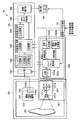
- FIG. 1 is a diagram illustrating an overall configuration of an imaging apparatus according to an embodiment of the present invention.
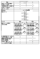
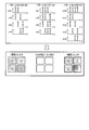
- FIG. 2 is a diagram illustrating (Configuration a) and (Configuration b).
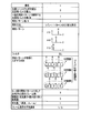
- FIG. 3 is a diagram illustrating (Configuration c).
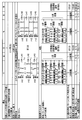
- FIG. 4 is a diagram illustrating (Configuration d) and (Configuration e).
- FIG. 5 is a diagram illustrating (Configuration f).
- FIG. 6 is a diagram showing a modification of one embodiment of the present invention.
- FIG. 1 is a diagram illustrating an overall configuration of an imaging apparatus according to an embodiment of the present invention.
- An imaging apparatus 100 illustrated in FIG. 1 includes an illumination unit 102, an imaging unit 104, an image processing unit 106, a display unit 108, and an imaging mode control unit 110.
- This imaging apparatus 100 basically irradiates the observation target 200 with illumination light from the illumination unit 102, captures light reflected or scattered by the observation target with the imaging unit 104, and is obtained by the imaging unit 104.
- the image signal is processed by the image processing unit 106.
- the imaging apparatus 100 causes the display unit 108 to display an image obtained by the processing of the image processing unit 106.
- the illumination unit 102 irradiates the observation target 200 with illumination light.
- the illumination unit 102 includes an illumination unit 1021 and an illumination switching control unit 1022.
- the illumination unit 1021 is configured to selectively irradiate illumination light of L different light wavelength bands.
- L is 3 or more, for example.
- the illumination unit 1021 as an example includes a light source 1021a, a waveguide 1021b, and a light distribution lens 1021c.
- the light source 1021a is L light sources having different light wavelength bands, and is, for example, a semiconductor laser (LD) or a super luminescent diode (SLD).
- FIG. 1 shows an example in which L is 3, and the three light sources 1021a shown in FIG. 1 respectively radiate R (red), G (green), and B (blue) illumination light.
- the waveguide 1021b is an optical fiber, for example, and is optically coupled to L light sources 1021a.
- the waveguide 1021b combines the illumination light emitted from the light source 1021a and emits it to the light distribution lens 1021c.
- the light distribution lens 1021c is, for example, a plano-concave lens, and shapes the illumination light emitted from the waveguide 1021b so as to have a predetermined light distribution spread angle and irradiates the observation target 200.
- the illumination switching control unit 1022 includes a characteristic information storage unit 1022a, an irradiation pattern setting unit 1022b, a drive pattern generation unit 1022c, and a light source driver 1022d, and illumination light of a predetermined N sets of irradiation patterns is emitted from the light source 1021a.
- the lighting unit 1021 is controlled so as to be irradiated.
- the irradiation pattern is a pattern indicating a combination of light of M light wavelength bands extracted at each timing of times t1, t2,..., TN.
- M is an integer of 2 or more and L or less
- N is an integer of 2 or more.
- the characteristic information storage unit 1022a stores characteristic information of the illumination unit 102 and the imaging unit 104.
- the characteristic information of the illuminating unit 102 includes information on connection terminals between the light source 1021a and the light source driver 1022d, information on the color (or wavelength band) that the light source 1021a can irradiate, and correspondence information between the drive intensity of the light source 1021a and the output of the light source 1021a.
- the characteristic information of the imaging unit 104 is mainly array information of the optical wavelength sensitivity characteristics of the imaging pixels constituting the imaging unit.
- Information indicating the presence / absence of a color filter of the imaging element 1042 For example, information indicating an array.
- the irradiation pattern setting unit 1022b sets N irradiation patterns so that the combinations of illumination light colors are different from each other in accordance with the input of required performance information of the imaging apparatus 100 from the imaging mode control unit 110, and sets the irradiation patterns to the set irradiation patterns. In response, the lighting unit control signal is generated.
- the required performance information is information for determining the performance of the imaging apparatus 100 such as whether the imaging apparatus 100 is set to a high frame rate mode, a high resolution mode, or a high sensitivity mode.
- the drive pattern generation unit 1022c Based on the characteristic information of the illumination unit 102 and the illumination unit control signal, the drive pattern generation unit 1022c outputs a light source driver control signal so that the illumination light of the illumination pattern set by the illumination pattern setting unit 1022b is emitted from the light source 1021a. Generate.
- the light source driver 1022d controls driving of the light source 1021a of the illumination unit 1021 according to the light source driver control signal.
- the illumination unit 102 can extract light in a predetermined M light wavelength bands and irradiate it at a predetermined time.
- the illumination unit 102 irradiates the observation target 200 with illumination light by changing N combinations of light of predetermined M light wavelength bands.
- L is the number of light wavelength bands that can be irradiated by the illumination unit
- M is the number of light wavelength bands to be irradiated in one set of irradiation patterns
- N is the number of irradiation patterns to be repeatedly irradiated.
- the imaging unit 104 captures an observation target and obtains an image signal related to the observation target.
- the imaging unit 104 includes an imaging lens 1041 and an imaging element 1042.
- the imaging lens 1041 is an optical system that images light reflected or scattered by the observation target 200 on the image sensor 1042.
- the image sensor 1042 converts an optical image formed through the imaging lens 1041 into an image signal as an electric signal.
- the imaging element 1042 includes a light receiving element 1042a and a color filter 1042b.
- the light receiving element 1042a is, for example, a photodiode arranged two-dimensionally, and performs photoelectric conversion.
- the color filter 1042b is provided in the light receiving element 1042a so as to correspond to each light receiving element 1042a, and makes an optical image of a specific wavelength band in the light from the observation target 200 incident on the corresponding light receiving element 1042a.
- the image sensor 1042 may not include the color filter 1042b. In this case, the image sensor 1042 does not have color selectivity.
- the imaging apparatus 100 is an observation environment in which only the illumination light from the illumination unit 102 is irradiated onto the observation target 200, that is, in an environment where there is substantially no influence of external light. The performance can be extracted most ideally. Therefore, the imaging apparatus 100 according to the present embodiment is configured to cover, for example, the illumination unit 102, the imaging unit 104, and the observation target 200 in an environment where the influence of external light other than the irradiation light from the illumination unit 102 is suppressed. It is preferable that the external light suppressing member 300 is used.
- the imaging apparatus 100 is suitable for applications such as a microscope apparatus and an endoscope apparatus that often acquire images in an environment that is substantially not affected by external light.
- ⁇ Lw, i ⁇ Fw, i (i 1,2, ..., L) (1)
- the spectrum width of the irradiation light is narrow.
- a laser light source, a super luminescent diode, or the like is preferable as the light source 1021a. If the condition of the expression (1) can be satisfied, the color reproducibility does not deteriorate even if the number M of light wavelength bands in each irradiation pattern increases. Further, high image display performance (resolution / frame rate / SN / color reproducibility, etc.) corresponding to the number M of light wavelength bands can be provided.
- the image processing unit 106 processes the image signal obtained by the imaging unit 104 to generate an image.
- the image processing unit 106 according to the present embodiment performs various processes according to the characteristics of the light source 1021a, the characteristics of the image sensor 1042, and a function request for image processing.
- FIG. 1 shows a typical configuration of the image processing unit 106. 1 includes an A / D converter 1061, a frame memory 1062, a secondary image generation unit 1063, a tertiary image generation unit 1064, a display mode switching unit 1065, an image correction unit 1066, have.
- the A / D converter 1061 samples the image signal obtained by the imaging unit 104 in synchronization with the input timing of the light source driver control signal generated by the drive pattern generation unit 1022c, and the sampled image signal is an image of a digital signal. It is converted into a signal (primary image information).
- the frame memory 1062 stores primary image information obtained by the A / D converter 1061. In the present embodiment, N pieces of primary image information are obtained by performing N times of imaging in accordance with N sets of irradiation patterns.
- the frame memory 1062 stores the N pieces of primary image information.
- the secondary image generation unit 1063 performs processing according to the light source driver control signal generated by the drive pattern generation unit 1022c on the N pieces of primary image information stored in the frame memory 1062 to obtain the secondary image information.
- the tertiary image generation unit 1064 processes the secondary image information as necessary to generate tertiary image information. Details of processing of the secondary image generation unit 1063 and the tertiary image generation unit 1064 will be described later.
- the display mode switching unit 1065 generates image information to be output to the image correction unit 1066 according to the display mode of the display unit 108 by using the secondary image information generated by the secondary image generation unit 1063 and the tertiary image generation unit 1064. Switch to the tertiary image information.
- the image correction unit 1066 performs correction processing necessary for display and recording on the secondary image information or the tertiary image information. This correction processing is, for example, correction of color temperature, correction of gamma characteristics, enhancement processing or suppression processing of a specific light wavelength (color component in image information).
- the display unit 108 displays a display frame based on at least one of the secondary image information and the tertiary image information corrected by the image correction unit 1066. That is, the display unit 108 displays the display frame based on the secondary image information and the display frame based on the tertiary image information independently, or displays based on the display frame based on the secondary image information and the tertiary image information. Display the frame at the same time. Which display is performed is determined by the display mode. The display mode is set by a user, for example.
- the imaging mode control unit 110 is a CPU, for example, and is a synchronization signal to each of the imaging element 1042 of the imaging unit 104, the drive pattern generation unit 1022c of the illumination unit 102, the secondary image generation unit 1063 of the image processing unit 106, and the display unit 108. To control these blocks synchronously.
- the imaging mode control unit 110 also inputs required performance information to the irradiation pattern setting unit 1022b. The required performance information is set by a user, for example.
- the imaging apparatus 100 basically has the configuration shown in FIG. However, the imaging apparatus 100 has six configurations, that is, (configuration a), (configuration b), and (configuration c) depending on how to set the irradiation pattern, whether or not the color filter 1042b is combined with the light receiving element 1042a, and the type of the color filter 1042b. ), (Configuration d), (configuration e), and (configuration f), and perform different operations according to the respective configurations.
- an operation corresponding to each configuration of the imaging apparatus 100 will be described.
- the required number of primary images are acquired from the start of the illumination operation, and the time taken to generate the final display frame image (secondary image or tertiary image) is adjusted.
- the average frame display speed is fast means that the display delay with respect to the moving observation object is small, that is, the movement of the observation object can be displayed naturally (smoothly) at a high frame rate.
- the average speed of the frame display is slow means that the display delay with respect to the moving observation target is large, that is, the time interval until the display is switched at a low frame rate, and the movement of the observation target is smooth. It means that it cannot be displayed.
- (Configuration a) and (Configuration b) are configurations using an irradiation pattern corresponding to the white broadband illumination method.
- (Configuration a) and (Configuration b) differ in the type of color filter 1042b. That is, the color filter 1042b in (Configuration a) is a primary color filter, and the color filter 1042b in (Configuration b) is a complementary color filter.
- the “primary color filter” in the present embodiment is one of the L light wavelength bands that can be irradiated by the illumination unit 1021, and is close to this light wavelength band on one light wavelength band or on the wavelength axis.
- a filter configured by two-dimensionally arranging filter elements capable of transmitting the continuous wavelength region in accordance with a continuous wavelength region including a plurality of optical wavelength bands. It is.
- the primary color filter of the present embodiment includes a filter element capable of transmitting R illumination light of incident light, and the incident light.
- the filter element is configured by two-dimensionally arranging a filter element that can transmit the G illumination light and a filter element that can transmit the B illumination light of the incident light.
- the primary color filter of the embodiment has a configuration in which four types of filter elements that can transmit only one of the incident lights R1, R2, G, and B of the incident light are two-dimensionally arranged.
- a filter element that can transmit only light in a wavelength range including wavelengths of R1 and R2 that are close to each other on the wavelength axis in incident light, and only G illumination light in incident light.
- a filter element configured by two-dimensionally arranging a filter element that can transmit only B illumination light of incident light.
- the “complementary color filter” in the present embodiment refers to a corresponding one of the light wavelength bands of L light wavelength bands that can be irradiated by the illumination unit 1021 or the light wavelength on the wavelength axis.
- filter elements capable of transmitting light obtained by subtracting the wavelength region are arranged two-dimensionally in accordance with the position of the light receiving element. It is the filter comprised by these.
- the complementary color filter of this embodiment includes a filter element capable of transmitting light obtained by subtracting R illumination light from incident light, and incident light.
- a filter element configured by two-dimensionally arranging a filter element capable of transmitting light obtained by subtracting G illumination light from G and a filter element capable of transmitting light obtained by subtracting B illumination light from incident light. is there.
- the illumination unit 1021 can irradiate illumination light of four colors R1, R2, G, and B
- the complementary color filter of the present embodiment receives each of R1, R2, G, and B of the incident light.
- Four types of filter elements that can transmit light obtained by subtracting only one of the light may be arranged in a two-dimensional manner, but as a modification, the incident light is close on the wavelength axis.
- a filter element capable of transmitting light in a wavelength range excluding light in a wavelength range including wavelengths of R1 and R2, a filter element capable of transmitting light obtained by subtracting G illumination light from incident light, and incident light is also included.
- a lighting unit control signal is generated to be illuminated.
- the drive pattern generation unit 1022c generates a light source driver control signal according to the illumination unit control signal and the characteristic information stored in the characteristic information storage unit 1022a.
- the light source driver 1022d drives the light source 1021a according to the light source driver control signal.
- the imaging unit 104 performs imaging in synchronization with illumination of the observation target by the illumination unit 102. Since the color filter 1042b of (Configuration a) is a primary color filter, each filter element transmits only illumination light in the corresponding optical wavelength band. That is, the R filter element transmits only the R illumination light. Similarly, the G filter element transmits only the G illumination light, and the B filter element transmits only the B illumination light.
- the A / D converter 1061 samples the image signal from each light receiving element 1042a of the imaging unit 104, and converts the sampled image signal into primary image information as a digital signal. To be stored in the frame memory 1062.
- primary image information necessary for color imaging that is, primary image information including all three RGB components is stored in the frame memory 1062 at each illumination light irradiation timing.
- the secondary image generation unit 1063 uses the light source driver control signal to irradiate the illumination pattern (which illumination light of L light wavelength bands is irradiated at each timing) and the presence / absence and type (primary color) of the color filter 1042b. Which of the filter and the complementary color filter is identified, and image processing for color imaging is performed on the primary image information according to the identification result.
- the secondary image generation unit 1063 of (Configuration a) synchronizes (three-plate) primary image information including R information, G information, and B information as color imaging processing. Each pixel performs processing to generate secondary image information having R information, G information, and B information.
- the display mode switching unit 1065 After the image processing by the secondary image generation unit 1063, the display mode switching unit 1065 outputs the secondary image information generated by the secondary image generation unit 1063 to the image correction unit 1066.
- the image correction unit 1066 performs correction processing necessary for display on the display unit 108 on the input secondary image information, and outputs it to the display unit 108. In response to this, the display unit 108 displays a color image.
- illumination light of one light wavelength band is incident on one light receiving element 1042a at each illumination light irradiation timing.
- the light reception amount per pixel for each frame in (Configuration a) is equal to the light reception amount in one light wavelength band.
- the resolution of (configuration a) is one pixel.
- (Configuration a) an image is generated at each irradiation pattern switching timing. That is, the image extraction time of (Configuration a) matches the irradiation pattern switching interval, and the average frame display speed matches the irradiation pattern switching speed.
- the average speed of frame display of (configuration a) is set as a reference value 1. This is for comparison with other configurations.
- each filter element transmits only the illumination light of the complementary color in the corresponding light wavelength band, that is, the illumination light obtained by subtracting the corresponding illumination light. That is, the filter element of R's complementary color (R ⁇ (bar)) transmits only R ⁇ illumination light, that is, G and B illumination light. Similarly, the G complementary color (G- (bar)) filter element transmits only G-light, that is, R and B illumination light, and B complementary color (B- (bar)). The filter element transmits only B-illumination light, that is, R and G illumination light.
- the secondary image generation unit 1063 of (Configuration b) performs R-information (that is, G + B), G-information (that is, R + B), B-information (that is acquired almost simultaneously) as color imaging processing ( That is, the difference between the information obtained by adding all R + G) and the R-, G-, B-independent information at a predetermined ratio, and the image corresponding to the R information, the G information, and the B information.
- Secondary image information is generated by performing a process of synchronizing information (three plates).
- the display mode switching unit 1065 After the image processing by the secondary image generation unit 1063, the display mode switching unit 1065 outputs the secondary image information generated by the secondary image generation unit 1063 to the image correction unit 1066.
- the image correction unit 1066 performs correction processing necessary for display on the display unit 108 on the input secondary image information, and outputs it to the display unit 108. In response to this, the display unit 108 displays a color image.
- one piece of secondary image information is generated from one piece of primary image information. Accordingly, the resolution of (configuration b) is one pixel, as in (configuration a).
- (Configuration b) acquisition of the number of primary image information and generation of secondary image information necessary for generating an image are performed within the irradiation pattern switching interval. That is, the image extraction time of (Configuration b) matches the irradiation pattern switching interval, and the average frame display speed matches the irradiation pattern switching speed.
- (Configuration b) is a configuration used in applications with higher sensitivity than (Configuration a).
- (Configuration b) a process for converting a complementary color signal into a primary color signal is required, and therefore in terms of color reproduction, it is inferior to (Configuration a).
- (Configuration c) is a configuration in the case of using an irradiation pattern corresponding to the field sequential illumination method.
- the illumination unit control signal is generated so that the illumination light B is emitted.
- the imaging device 1042 of the imaging unit 104 of (configuration c) does not have the color filter 1042b and has no color selectivity. Therefore, the illumination light is received by the light receiving element 1042a as it is without being absorbed by the color filter. That is, at the timing when the R illumination light is irradiated, the R illumination light is received by the light receiving element 1042a. Similarly, at the timing when the G illumination light is irradiated, the G illumination light is received by the light receiving element 1042a, and at the timing when the B illumination light is irradiated, the B illumination light is received by the light receiving element 1042a.
- the secondary image generation unit 1063 of (configuration c) performs the same synchronization processing as that of (configuration a). However, in the case of (Configuration c), primary image information necessary for color imaging is obtained by switching illumination light three times. Therefore, the secondary image generation unit 1063 of (Configuration c) identifies the illumination light switching timing based on the light source driver control signal, whereby the primary image information 1 of R, the primary image information 2 of G, Secondary image information is generated by performing a process of synchronizing (three plates) when the primary image information 3 of B is complete.
- the display mode switching unit 1065 After the image processing by the secondary image generation unit 1063, the display mode switching unit 1065 outputs the secondary image information generated by the secondary image generation unit 1063 to the image correction unit 1066.
- the image correction unit 1066 performs correction processing necessary for display on the display unit 108 on the input secondary image information, and outputs it to the display unit 108. In response to this, the display unit 108 displays a color image.
- illumination light of one light wavelength band is incident on one light receiving element 1042a at every illumination light irradiation timing.
- one piece of secondary image information is generated using three pieces of primary image information, it can be said that one light receiving element 1042a corresponds to L pixels. Therefore, the amount of light per pixel of (configuration c) is 1 / L times (1/3 times in the example) of (configuration a), and the amount of light per pixel in (configuration c) is (configuration a). N / L times (1x in the example).
- the spatial resolution is approximately L times (3 times in the example) compared to (Configuration a).
- the image extraction time of (configuration c) is N times (3 times in the example) the irradiation pattern switching interval, and the average frame display speed is 1 / N times (in the example, the irradiation pattern switching speed). 1/3 times).
- (Configuration c) is a configuration that is used for higher resolution applications than (Configuration a).
- the average speed of frame display is inferior to (configuration a).
- the imaging device 100 of (Configuration d) and (Configuration e) will be described with reference to FIG. (Configuration d) and (Configuration e) described below are “a plurality of light sources that extract not only one color but also a predetermined plurality of colors using a light source that can irradiate a plurality of colors to an observation target.
- the irradiation pattern is set, and irradiation is performed while switching a plurality of irradiation patterns having different combinations of illumination colors ”.
- the display performance is improved by switching the irradiation pattern.
- (Configuration d) is an imaging apparatus in which N sets of irradiation patterns for extracting and irradiating illumination light of M light wavelength bands from illumination light of L light wavelength bands are prepared, and the N irradiation patterns are sequentially switched. 100, the image sensor 1042 does not include the color filter 1042b.
- the imaging unit 104 does not include the color filter 1042b. Therefore, the illumination light is received by the light receiving element 1042a as it is without being absorbed by the color filter. That is, at the timing when the G and B illumination lights are irradiated, the G and B illumination lights are received by the light receiving element 1042a. This is the same as when the R ⁇ illumination light is received by the light receiving element 1042a. Similarly, at the timing when the R and B illumination lights are irradiated, the R and B illumination lights are received by the light receiving element 1042a. This is the same as when the G ⁇ illumination light is received by the light receiving element 1042a. Further, at the timing when the R and G illumination lights are irradiated, the R and G illumination lights are received by the light receiving element 1042a. This is the same as when the B ⁇ illumination light is received by the light receiving element 1042a.
- the secondary image generation unit 1063 of (configuration d) performs image processing that combines the image processing of (configuration b) and (configuration c). That is, the secondary image generation unit 1063 generates secondary image information from the three pieces of primary image information as in (Configuration c). However, in the case of (Configuration d), primary image information 1, 2, and 3 including complementary color information is obtained. Therefore, the secondary image generation unit 1063 of (configuration d) performs primary image information 1, 2 including R-information, G-information, and B-information in the same manner as (configuration b). 3 and the R-, G-, and B-individual information at a predetermined ratio, and the R information, the G information, and the image information corresponding to the B information.
- the secondary image information is generated by performing a process of synchronizing (three plates).
- the display mode switching unit 1065 After the image processing by the secondary image generation unit 1063, the display mode switching unit 1065 outputs the secondary image information generated by the secondary image generation unit 1063 to the image correction unit 1066.
- the image correction unit 1066 performs correction processing necessary for display on the display unit 108 on the input secondary image information, and outputs it to the display unit 108. In response to this, the display unit 108 displays a color image.
- illumination light of two light wavelength bands is incident on one light receiving element 1042a at each illumination light switching timing. Accordingly, when viewed as one frame, the amount of light per pixel of (configuration d) is twice that of (configuration a). More generally, illumination light of M light wavelength bands enters one light receiving element 1042a at each illumination light switching timing. Accordingly, the light amount per pixel of (Configuration d) is M times that of (Configuration a) on average, but since one light receiving element 1042a corresponds to L pixels, the light amount per pixel is M. / L times, and the amount of light per pixel in one frame is N ⁇ M / L times. In (configuration d), since one light receiving element 1042a functions as L pixels, the spatial resolution is L times that of (configuration a).
- the image extraction time of (Configuration d) is three times the irradiation pattern switching interval, and the average frame display speed is 1/3 times the irradiation pattern switching speed.
- the image extraction time of (Configuration d) is N times the irradiation pattern switching interval, and the average frame display speed is 1 / N times the irradiation pattern switching speed.
- (Configuration d) is a configuration that is used in applications with higher sensitivity and higher resolution than (Configuration a).
- the average speed of frame display is inferior to (Configuration a).
- (Configuration d) has an advantage of higher sensitivity than (Configuration c) while having a resolution equivalent to that of (Configuration c) having a high resolution.
- (Configuration e) is an imaging apparatus that prepares N sets of irradiation patterns for extracting and irradiating illumination light of M light wavelength bands from illumination light of L light wavelength bands, and sequentially switches the N irradiation patterns.
- the image sensor 1042 has a primary color filter.
- the imaging unit 104 has a primary color filter. Accordingly, only the illumination light corresponding to each filter element is received by the light receiving element 1042a. That is, at the timing when the G and B illumination lights are irradiated, the R filter element does not transmit the illumination light, the G filter element transmits only the G illumination light, and the B filter element transmits the B illumination light. Permeate only. At the timing when the R and B illumination lights are irradiated, the R filter element transmits only the R illumination light, the G filter element does not transmit the illumination light, and the B filter element transmits only the B illumination light. Make it transparent.
- the R filter element transmits only the R illumination light
- the G filter element transmits only the G illumination light
- the B filter element transmits the illumination light. I won't let you. In this way, in (Configuration e), primary color information corresponding to two sets of different color components is obtained at each timing.
- secondary image generation unit 1063 generates secondary image information from primary color information obtained at two successive timings. That is, the secondary image generation unit 1063 performs secondary processing by performing a process of synthesizing (three-plate) the G information and B information obtained at timing 1 and the R information obtained at timing 2. Generate image information. Further, the secondary image generation unit 1063 performs secondary processing by performing a process of synchronizing (three plates) the B information obtained at timing 2 with the R information and G information obtained at timing 3. Generate image information.
- the display mode switching unit 1065 After the image processing by the secondary image generation unit 1063, the display mode switching unit 1065 outputs the secondary image information generated by the secondary image generation unit 1063 to the image correction unit 1066.
- the image correction unit 1066 performs correction processing necessary for display on the display unit 108 on the input secondary image information, and outputs it to the display unit 108. In response to this, the display unit 108 displays a color image.
- illumination light of one light wavelength band is incident on one light receiving element 1042a at each illumination light switching timing, but when viewed in terms of the amount of light per pixel of one frame. It becomes smaller than (Configuration a).
- the spatial resolution is the same as that in (Configuration a).
- the image extraction time of (Configuration e) is twice as long as the irradiation pattern switching interval, and the average frame display speed is 1 ⁇ 2 times the irradiation pattern switching speed.
- the image extraction time of (configuration e) is (N-1) times the irradiation pattern switching interval, and the average frame display speed is 1 / (N-1) of the irradiation pattern switching speed. ) Doubled.
- (Configuration e) is a configuration used in a higher frame rate mode than (Configuration c).
- the settings of L, M, and N are not limited to those shown in the examples.
- the number of irradiation patterns N 4, and one of the four irradiation patterns may be irradiated with all of the illumination light in the three light wavelength bands.
- the imaging device 100 having the (configuration f) will be described with reference to FIG. (Configuration f) described below is similar to (Configuration d) and (Configuration e). “Using a light source that can irradiate a plurality of colors to an observation target, not only one color but also a predetermined plurality of colors. A plurality of irradiation patterns for extracting and irradiating light are set, and irradiation is performed while switching a plurality of irradiation patterns having different combinations of illumination colors. ”
- the image sensor 1042 has a complementary color filter. It is a configuration.
- the imaging unit 104 of (Configuration f1) to (Configuration f6) has a complementary color filter. Therefore, only the illumination light obtained by subtracting the illumination light corresponding to each filter element is received by the light receiving element 1042a. That is, at the timing when the G and B illumination lights are irradiated, the R ⁇ filter element transmits the G and B illumination lights as they are, the G ⁇ filter element transmits only the B illumination light, and the B ⁇ The filter element transmits only G illumination light. At the timing when the R and B illumination lights are applied, the R ⁇ filter element transmits only the B illumination light, the G ⁇ filter element transmits the R and B illumination light as they are, and the B ⁇ filter element. Transmits only R illumination light. At the timing when the R and G illumination lights are applied, the R ⁇ filter element transmits only the G illumination light, the G ⁇ filter element transmits only the R illumination light, and the B ⁇ filter element remains as it is. Transmits R and B illumination light.
- the secondary image generation unit 1063 of (configuration f1) recognizes the signal obtained from the light receiving element 1042a corresponding to the R ⁇ filter element as an R complementary color signal, and uses the G ⁇ filter.
- a signal obtained from the light receiving element 1042a corresponding to the element is recognized as a B primary color signal
- a signal obtained from the light receiving element 1042a corresponding to the B ⁇ filter element is recognized as a G primary color signal, and an image including these information Processing for generating secondary image information 1 using the information as primary image information 1 is performed.
- the secondary image generation unit 1063 recognizes the signal obtained from the light receiving element 1042a corresponding to the R ⁇ filter element as a B primary color signal and corresponds to the G ⁇ filter element.
- the signal obtained from the received light receiving element 1042a is recognized as a G complementary color signal
- the signal obtained from the light receiving element 1042a corresponding to the B-filter is recognized as an R primary color signal
- image information including these information is first-order. Processing for generating secondary image information 2 as image information 2 is performed.
- a signal obtained from the light receiving element 1042a corresponding to the R ⁇ filter element is recognized as a G primary color signal
- a signal obtained from the light receiving element 1042a corresponding to the G ⁇ filter element is R Is recognized as a primary color signal
- a signal obtained from the light receiving element 1042a corresponding to the B ⁇ filter element is recognized as a complementary color signal for B, and image information including these information is used as primary image information 3 for secondary image information 3.
- the secondary image generation unit 1063 of (Configuration f1) repeats switching of the irradiation pattern, and converts the RGB primary color signals obtained by light irradiation with the previous or second previous irradiation pattern in time.
- the display mode switching unit 1065 After the image processing by the secondary image generation unit 1063, the display mode switching unit 1065 outputs the secondary image information generated by the secondary image generation unit 1063 to the image correction unit 1066.
- the image correction unit 1066 performs correction processing necessary for display on the display unit 108 on the input secondary image information, and outputs it to the display unit 108. In response to this, the display unit 108 displays a color image.
- (Configuration f1) is thus configured to be used in a mode with higher sensitivity than (Configuration a) and a higher frame rate than (Configuration c).
- (Configuration f2) is the same as (Configuration f1) until the secondary image information is obtained, and further differs in that tertiary image information is generated as a display image. That is, the secondary image generation unit 1063 of (configuration f2) inputs the latest three pieces of secondary image information 1, 2, and 3 to the tertiary image generation unit 1064. The tertiary image generation unit 1064 combines the secondary image information 1, 2, and 3 to generate one tertiary image information including information on all light wavelength bands of RGB. The display mode switching unit 1065 outputs the tertiary image information generated by the tertiary image generation unit 1064 to the image correction unit 1066.
- the image correction unit 1066 performs correction processing necessary for display on the display unit 108 on the input tertiary image information, and outputs it to the display unit 108. In response to this, the display unit 108 displays a color image.
- the primary image information 1, 2, 3 and the secondary image information 1, 2, 3 are used to generate tertiary image information including information on all light wavelength bands of RGB. May be.
- one piece of secondary image information is generated using three pieces of primary image information in the same manner as (configuration c). That is, also in (Configuration f2), since one light receiving element functions as L pixels, the spatial resolution is L times that of (Configuration a). On the other hand, the average frame display speed is 1 / N times that of (Configuration a). Others are the same as (Configuration f1).
- (Configuration f3) is the same as (Configuration f2) until the generation of the tertiary image information.
- the display mode switching unit 1065 of (Configuration f3) includes the secondary image information generated by the secondary image generation unit 1063 and the tertiary image information generated by the tertiary image generation unit 1064. Is selected as the final display frame and output to the image correction unit 1066.
- the image correction unit 1066 performs correction processing necessary for display on the display unit 108 on the input image information and outputs the processed image information to the display unit 108. In response to this, the display unit 108 displays a color image.
- the most recent secondary image information is used to generate the tertiary image information. Therefore, selection of image information by the display mode switching unit 1065 is performed from the third frame onward.
- selection of image information by the display mode switching unit 1065 is performed from the third frame onward.
- an example in which either an image based on secondary image information or an image based on tertiary image information is displayed has been described, but both images may be displayed in parallel.
- the image display mode corresponding to (configuration f1) and the image display mode corresponding to (configuration f2) can be switched as necessary. That is, when high resolution is desired, it can be displayed with the image characteristics of (Configuration f2) (high resolution but low frame rate), and when it is desired to smoothly display the movement of a fast observation target, (Configuration f1) It is possible to display with image characteristics (not high resolution but high frame rate). In this way, it is possible to select which of the resolution and the frame rate has priority according to the image display mode, or to simultaneously display both using both modes.
- (Configuration f4) is the same as (Configuration f1) until the acquisition of the primary image information.
- a process of generating secondary image information 1 by recognizing it as a primary color signal and using image information including such information as primary image information 1 is performed.
- the obtained signal is recognized as a complementary color signal of B, and processing for generating secondary image information 2 using image information including these pieces of information as primary image information 2 is performed.
- the obtained signal is recognized as an R complementary color signal, and the image information including these pieces of information is used as primary image information 3 to generate secondary image information 3.
- the primary image information obtained in (Configuration f4) has either primary color information of the RGB light wavelength band or complementary color information of the RGB light wavelength band. Therefore, the secondary image information 1, 2, and 3 can be sent to the image correction unit 1066 and further to the display unit 108 without passing through the tertiary image generation unit 1064. Note that in order to simplify image processing, when image processing is performed using only primary color signals, the secondary image information 3 may not be used to generate a final image. In the description relating to the effect of (Configuration f4) described below, description of the effect in the case where the secondary image information 3 is not used for generating the final image is omitted.
- (Configuration f5) is the same as (Configuration f4) until generation of secondary image information, and further differs in that tertiary image information is generated as a display image. That is, the secondary image generation unit 1063 of (configuration f5) inputs the latest three pieces of secondary image information 1, 2, and 3 to the tertiary image generation unit 1064. The tertiary image generation unit 1064 combines the secondary image information 1, 2, and 3 to generate one tertiary image information including information on all light wavelength bands of RGB.
- the display mode switching unit 1065 outputs the tertiary image information generated by the tertiary image generation unit 1064 to the image correction unit 1066.
- the image correction unit 1066 performs correction processing necessary for display on the display unit 108 on the input tertiary image information, and outputs it to the display unit 108. In response to this, the display unit 108 displays a color image.
- (Configuration f6) is the same as (Configuration f5) until the generation of the tertiary image information.
- the display mode switching unit 1065 in (Configuration f6) includes the secondary image information generated by the secondary image generation unit 1063 and the tertiary image information generated by the tertiary image generation unit 1064. Is selected as the final image and output to the image correction unit 1066.
- the image correction unit 1066 performs correction processing necessary for display on the display unit 108 on the input image information and outputs the processed image information to the display unit 108. In response to this, the display unit 108 displays a color image.
- the most recent secondary image information is used to generate the tertiary image information. Therefore, selection of image information by the display mode switching unit 1065 is performed from the third frame onward.
- selection of image information by the display mode switching unit 1065 is performed from the third frame onward.
- an example in which either an image based on secondary image information or an image based on tertiary image information is displayed has been described, but both images may be displayed in parallel.
- the image display mode corresponding to (configuration f4) and the image display mode corresponding to (configuration f5) can be switched as necessary. That is, when high resolution is desired, it can be displayed with the image characteristics of (configuration f5) (high resolution but low frame rate), and when it is desired to smoothly display the movement of a fast observation target, (configuration f4). It is possible to display with image characteristics (not high resolution but high frame rate). In this way, it is possible to select which of the resolution and the frame rate has priority according to the image display mode, or to simultaneously display both using both modes.
- the complementary color information in the primary image information obtained by (Configuration f1) is set to 1/2 of the total signal received by the three light receiving elements 1042a in the full band (RGB) and the timing 1, 2, 3 can be converted into primary color information by taking a difference from the complementary color signal acquired in each of the three.
- the irradiation pattern is set according to the characteristics of the imaging unit 104 and the performance required for the imaging device 100, thereby preventing the size of the device from being increased and the basics of the imaging device. Specific performance can be selected as needed.
- Generate unit control signals That is, the pattern A2 shown in (Configuration d), (Configuration e), and (Configuration f) is divided into a pattern B2 and a pattern B4.
- the irradiation patterns D0 to D4 shown in the upper part of FIG. 6 are obtained by adding an irradiation pattern D0 for irradiating all of RGBO illumination light to the irradiation patterns B1 to B4.
- the illumination unit control signal is generated so that the R and O illumination lights are emitted as the pattern D4.
- the lower part of FIG. 6 shows the arrangement of the filters.
- the four primary color filters shown in the lower part of FIG. 6 are two-dimensionally arranged with filter elements capable of transmitting a corresponding one of the four light wavelength band incident lights that can be irradiated by the illumination unit 1021. It is a filter constituted by this. That is, the primary color filter includes a filter element capable of transmitting R illumination light of incident light, a filter element capable of transmitting G illumination light of incident light, and B illumination light of incident light.
- the filter element is configured by two-dimensionally arranging a filter element that can transmit light and a filter element that can transmit O illumination light of incident light.
- the filter 6 has a two-dimensional filter element that can transmit light obtained by subtracting one corresponding light from light of L light wavelength bands that can be irradiated by the illumination unit 1021. It is the filter comprised by arrange
- the filter is configured by two-dimensionally arranging a filter element capable of transmitting light obtained by subtracting illumination light and a filter element capable of transmitting light obtained by subtracting O illumination light from incident light.
- each of the (configuration a) to (configuration c) (1-band / pattern switching illumination), (configuration d), and (configuration f) (multi-band / pattern switching illumination) is used as the illumination pattern.
- the lighting pattern switching setting is fixed for the case (that is, M is fixed), the image processing algorithm of the corresponding image processing means is shown, and the image characteristics that can be generated by this algorithm and the switching variations thereof are described
- the number L of light wavelength bands that the illumination unit can irradiate need not be the same as the number of primary color filters or complementary color filters.
- the number of primary color filter elements shown in FIG. 6 may be reduced by one to provide three types of filter arrangements: RO filter, G filter, and B filter. (The RO filter transmits only R and O light and blocks G and B. The G filter transmits only G. The B filter transmits only B).
- the number of complementary color filter elements shown in FIG. 6 may be reduced by one to form three types of filter arrangements: RO-filter, G-filter, and B-filter (the RO-filter blocks R and O light). , G and B are transmitted. The G-filter blocks only G. The B-filter blocks only B).
- the imaging device of the imaging unit is configured as follows: “When the filter array combined with the light receiving element array is a monochrome filter, a complementary color filter, and a primary color The case where it is a filter ”has been described, but the case where the image sensor is configured so that the optical wavelength sensitivity characteristic is in a predetermined arrangement without being combined with the filter is included (that is, different light is applied to each pixel of the image sensor). Provide wavelength sensitivity characteristics).
- “photodetection element that does not limit the sensitivity characteristic with respect to the light wavelength” when “light receiving element” is used, and “sensitivity characteristic with respect to the light wavelength” when “imaging pixel” is described.
- photodetection element including is described as “imaging element”, it means “an assembly of an array of imaging pixels (light detection elements including sensitivity characteristics with respect to the light wavelength)”.
Landscapes
- Physics & Mathematics (AREA)
- Health & Medical Sciences (AREA)
- Life Sciences & Earth Sciences (AREA)
- Engineering & Computer Science (AREA)
- Surgery (AREA)
- Optics & Photonics (AREA)
- General Physics & Mathematics (AREA)
- Multimedia (AREA)
- Nuclear Medicine, Radiotherapy & Molecular Imaging (AREA)
- Veterinary Medicine (AREA)
- Radiology & Medical Imaging (AREA)
- Biophysics (AREA)
- Biomedical Technology (AREA)
- Heart & Thoracic Surgery (AREA)
- Medical Informatics (AREA)
- Molecular Biology (AREA)
- Animal Behavior & Ethology (AREA)
- General Health & Medical Sciences (AREA)
- Public Health (AREA)
- Pathology (AREA)
- Signal Processing (AREA)
- Astronomy & Astrophysics (AREA)
- Chemical & Material Sciences (AREA)
- Analytical Chemistry (AREA)
- Computer Vision & Pattern Recognition (AREA)
- Endoscopes (AREA)
- Color Television Image Signal Generators (AREA)
- Studio Devices (AREA)
- Instruments For Viewing The Inside Of Hollow Bodies (AREA)
- Microscoopes, Condenser (AREA)
- Closed-Circuit Television Systems (AREA)
Abstract
撮像装置(100)は、照明光を観察対象に照射する照明部102と、観察対象を撮像して画像信号を取得する撮像部(104)と、前記画像信号を処理する画像処理部(106)とを備える。照明部(102)は、互いに異なる複数の光波長バンドの照明光を選択的に照射する照明ユニット(1021)と、照明ユニット(1021)から照射される照明光の光波長バンドの組み合わせを互いに異ならせるように照明ユニット制御信号を生成して照明ユニット(1021)を制御する照明切替制御ユニット(1022)とを有する。画像処理部(106)は、照明ユニット制御信号と撮像部(104)の特性情報とに基づいて画像信号を処理する。
Description
本発明は、撮像装置、内視鏡装置及び顕微鏡装置に関する。
従来、画像をカラー化する方式として、ブロードな光波長を有する照明光(例えば、白色光)と受光素子の上にカラーフィルタが設けられた撮像素子との組み合わせにより画像をカラー化する一般的な方式(以後、このような方式を白色ブロードバンド照明方式と呼ぶ)が知られている。また、受光素子の上にカラーフィルタが設けられていないような色選択性のない撮像素子を用いて画像をカラー化する方式として、日本国特開昭63-227293号公報において提案されているような、フィールド毎に異なる単色の照明光を観察対象に照射し、フィールド順次で撮像素子から得られる信号を同時化してカラー画像を得る方式(以後、このような方式を面順次照明方式と呼ぶ)が知られている。
白色ブロードバンド照明方式においては、カラーフィルタの種類(補色フィルタであるか又は原色フィルタであるか)により、感度及び色再現性が異なることが知られている。そして、白色ブロードバンド照明方式において、感度と色再現とは互いにトレードオフの関係にあることも知られている。原色フィルタを用いた白色ブロードバンド照明方式の場合、1個の受光素子には単色の照明光しか入射しない。一方で、補色フィルタを用いた白色ブロードバンド照明方式の場合、1個の受光素子には複数色の照明光が入射する。したがって、原色フィルタを用いた場合の感度やS/Nは、補色フィルタを用いた場合の感度やS/Nに比べて劣っている。また、原色フィルタを用いた白色ブロードバンド照明方式の場合、信号の変換をしなくともカラー画像を生成することが可能である。一方、補色フィルタを用いた白色ブロードバンド照明方式の場合、個々の受光素子から得られる補色信号を原色信号に変換しなければカラー画像を生成することができない。この変換の過程においては、個々の受光素子の周囲の受光素子からの補色信号を参照する必要がある。したがって、補色フィルタを用いた場合の色再現性は、原色フィルタを用いた場合の色再現性に比べて低くなる。
また、面順次照明方式を用いた場合、フィールド毎に撮像素子の全ての受光素子を1つの色について使用できるので、白色ブロードバンド照明方式に対して高い解像度の画像が得られる。しかしながら、面順次照明方式では、各色の照明光が照射されたときに得られる各々のフィールド画像を全色分合成することによりカラー画像を生成できるようになる。このため、面順次照明方式は、白色ブロードバンド照明方式に対してフレームレートが低下する。したがって、動きのある観察対象の画像を表示させる際に表示遅れや画像の動きを滑らかに表示しにくいなどの問題が発生する可能性がある。
このように、原色フィルタを用いた白色ブロードバンド照明方式、補色フィルタを用いた白色ブロードバンド照明方式及び面順次照明方式は、それぞれが長所と短所を備えている。したがって、これらの照明方式を単独で用いたとしても、高解像度化、高色再現性、高フレームレート化、高感度化といった撮像装置の基本的な性能に対する要求のすべてを満たすことは困難であり、また、これらの基本的な性能の何れを満たさせるかを必要に応じて選択することも困難である。これに対し、複数種類の受光素子とフィルタの組み合わせを用意し、これに対応して、上述の3種類の照明方式の選択ができるような構成とすると、装置が大型化し易い。
本発明は、前記の事情に鑑みてなされたもので、装置の大型化を防止しつつ、撮像装置の基本的な性能を必要に応じて選択することが可能な撮像装置、並びにそれを備える顕微鏡装置及び内視鏡装置を提供することを目的とする。
前記の目的を達成するために、本発明の一態様の撮像装置は、照明光を観察対象に照射する照明部と、所定の配列で所定の光波長感度特性を有する撮像画素が配置された撮像素子を有し、前記観察対象を前記撮像素子で撮像して前記観察対象に係る画像信号を取得する撮像部と、前記画像信号を処理する画像処理部とを具備し、前記照明部は、互いに異なる光波長バンドの照明光を選択的に照射するように構成された照明ユニットと、前記撮像部の前記撮像画素の光波長感度特性の配列情報と要求性能情報とに基づいて前記照明ユニットから照射される照明光の光波長バンドの組み合わせを互いに異ならせるように複数組の照射パターンのそれぞれに対応した照明ユニット制御信号を生成し、前記照明ユニット制御信号の切り替えにより、互いに異なる組の照射パターンで前記照明ユニットから前記照明光が順次照射されるように前記照明ユニットを制御する照明切替制御ユニットとを有し、前記画像処理部は、前記照明ユニット制御信号と前記撮像部の前記撮像画素の光波長感度特性の配列情報とに基づいて前記画像信号を処理する。
以下、図面を参照して本発明の実施形態を説明する。図1は、本発明の一実施形態に係る撮像装置の全体構成を示す図である。図1に示す撮像装置100は、照明部102と、撮像部104と、画像処理部106と、表示部108と、撮像モード制御部110とを有している。この撮像装置100は、基本的には、照明部102から観察対象200に照明光を照射し、観察対象で反射、散乱等された光を撮像部104で撮像し、撮像部104で得られた画像信号を画像処理部106で処理する。そして、この撮像装置100は、画像処理部106の処理によって得られた画像を表示部108に表示させる。
照明部102は、照明光を観察対象200に照射する。この照明部102は、照明ユニット1021と、照明切替制御ユニット1022とを有している。
照明ユニット1021は、L個の異なる光波長バンドの照明光を選択的に照射するように構成されている。本実施形態においてLは例えば3以上である。一例の照明ユニット1021は、光源1021aと、導波路1021bと、配光レンズ1021cとを有している。光源1021aは、異なる光波長バンドを有するL個の光源であって、例えば半導体レーザ(LD)やスーパールミネッセントダイオード(SLD)である。図1は、Lが3の例を示しており、図1に示す3個の光源1021aは、それぞれ、R(赤)、G(緑)、B(青)の照明光を照射する。導波路1021bは、例えば光ファイバであってL個の光源1021aに光学的に結合されている。この導波路1021bは、光源1021aから照射された照明光を合波し、配光レンズ1021cに射出する。配光レンズ1021cは、例えば平凹レンズであり、導波路1021bから射出された照明光を所定の配光拡がり角になるように整形して観察対象200に照射する。
照明切替制御ユニット1022は、特性情報記憶部1022aと、照射パターン設定部1022bと、ドライブパターン発生部1022cと、光源ドライバ1022dとを有し、所定のN組の照射パターンの照明光が光源1021aから照射されるように照明ユニット1021を制御する。また、照射パターンとは、時刻t1,t2,…,tNのそれぞれのタイミングで抽出されるM個の光波長バンドの光の組み合わせを示すパターンである。ここで、Mは2以上かつL以下の整数であり、Nは2以上の整数である。この他、照明光の照射強度及び照射時間を照射パターンに含めてもよい。特性情報記憶部1022aは、照明部102及び撮像部104の特性情報を記憶している。照明部102の特性情報は、光源1021aと光源ドライバ1022dとの接続端子の情報、光源1021aの照射可能な色(又は波長バンド)の情報、光源1021aのドライブ強度と光源1021aの出力との対応情報等である。また、撮像部104の特性情報は、主として撮像部を構成する撮像画素の光波長感度特性の配列情報であり、後で説明する撮像素子1042のカラーフィルタの有無を示す情報、カラーフィルタの種類や配列を示す情報等である。照射パターン設定部1022bは、撮像モード制御部110からの撮像装置100の要求性能情報の入力に従って、照明光の色の組み合わせが互いに異なるようにN組の照射パターンを設定し、設定した照射パターンに応じて照明ユニット制御信号を生成する。要求性能情報は、撮像装置100を高フレームレートモードとするのか、高解像度モードとするか、高感度モードとするかといった撮像装置100の性能を決めるための情報である。ドライブパターン発生部1022cは、照明部102の特性情報と照明ユニット制御信号とに基づき、照射パターン設定部1022bで設定された照射パターンの照明光が光源1021aから照射されるように光源ドライバ制御信号を生成する。光源ドライバ1022dは、光源ドライバ制御信号に従って照明ユニット1021の光源1021aの駆動を制御する。
以上のような照明ユニット1021と照明切替制御ユニット1022とを有することにより、照明部102は、所定のM個の光波長バンドの光を抽出して所定時刻に照射可能である。また、照明部102は、所定のM個の光波長バンドの光の組み合わせをN通りに変化させて照明光を観察対象200に照射する。ここで、Lは照明ユニットが照射可能な光波長のバンド数、Mは1組の照射パターンの中で照射する光波長バンドの数、Nは繰り返し照射する照射パターンの数である。
撮像部104は、観察対象を撮像して観察対象に係る画像信号を得る。撮像部104は、結像レンズ1041と撮像素子1042とを有している。結像レンズ1041は、観察対象200で反射、散乱等された光を撮像素子1042に結像させる光学系である。撮像素子1042は、結像レンズ1041を介して結像された光学像を電気信号としての画像信号に変換する。撮像素子1042は、受光素子1042aとカラーフィルタ1042bとを有している。受光素子1042aは、例えば2次元状に配置されたフォトダイオードであり、光電変換を行う。カラーフィルタ1042bは、各受光素子1042aに対応するように受光素子1042aに設けられ、観察対象200からの光のうちの特定の波長バンドの光学像を対応する受光素子1042aに入射させる。後で詳しく説明するが、撮像素子1042は、カラーフィルタ1042bを有していない場合もある。この場合、撮像素子1042は、色選択性を有さないことになる。
本実施形態における撮像装置100は、観察対象200に対して、照明部102からの照明光のみが観察対象200に照射される観察環境下、すなわち実質的に外光の影響が殆どない環境下においてその性能を最も理想的に引き出すことができる。したがって、本実施形態における撮像装置100は、照明部102からの照射光以外の外光による影響が抑制される環境下、例えば、照明部102、撮像部104、及び観察対象200を覆うように構成された外光抑制部材300の中で使用されることが望ましい。外光抑制部材300の中に照明部102、撮像部104、及び観察対象200を配置できない場合には、画像処理の段階で、外光による画像信号の影響をキャンセルし、照射パターンのみによる画像信号を得るようにすることが望ましい。このように、本実施形態の撮像装置100は、実質的に外光による影響が殆どない環境下で画像を取得することが多い顕微鏡装置や内視鏡装置などの用途に好適である。
また、照明ユニット1021の照射可能なL個の光波長バンドの光の波長バンド幅をλLw,i(i=1,2,…,L)とし、撮像素子1042に設けられるカラーフィルタ1042bの波長バンド幅をλFw,i(i=1,2,…,L)とすると、λLw,iとλFw,iとは以下の(式1)の条件を満足していることが望ましい。
λLw,i<λFw,i (i=1,2,…,L) (1)
(1)式の条件を余裕を持って満足するには、照射光のスペクトル幅は狭いほうがよい。したがって、光源1021aとしては、レーザ光源やスーパールミネッセントダイオードなどが好適である。(1)式の条件を満足することができれば、各照射パターンにおける光波長バンドの数Mが増えても色再現性が低下しない。また、光波長バンドの数Mに応じた高い画像表示性能(解像度/フレームレート/SN/色再現性など)を提供することができる。
λLw,i<λFw,i (i=1,2,…,L) (1)
(1)式の条件を余裕を持って満足するには、照射光のスペクトル幅は狭いほうがよい。したがって、光源1021aとしては、レーザ光源やスーパールミネッセントダイオードなどが好適である。(1)式の条件を満足することができれば、各照射パターンにおける光波長バンドの数Mが増えても色再現性が低下しない。また、光波長バンドの数Mに応じた高い画像表示性能(解像度/フレームレート/SN/色再現性など)を提供することができる。
画像処理部106は、撮像部104で得られた画像信号を処理して画像を生成する。本実施形態における画像処理部106は、光源1021aの特性及び撮像素子1042の特性、画像処理の機能要求に応じて多様な処理を行う。図1は、画像処理部106の典型的な構成を示している。図1の画像処理部106は、A/D変換器1061と、フレームメモリ1062と、2次画像生成部1063と、3次画像生成部1064と、表示モード切替部1065と、画像補正部1066とを有している。
A/D変換器1061は、ドライブパターン発生部1022cで発生された光源ドライバ制御信号の入力タイミングに同期して撮像部104で得られた画像信号をサンプリングし、サンプリングした画像信号をデジタル信号の画像信号(1次画像情報)に変換する。フレームメモリ1062は、A/D変換器1061で得られた1次画像情報を記憶する。本実施形態においては、N組の照射パターンに応じたN回の撮像が行われることにより、N枚の1次画像情報が得られる。フレームメモリ1062は、このN枚の1次画像情報をそれぞれ記憶する。2次画像生成部1063は、フレームメモリ1062に記憶されたN枚の1次画像情報に対し、ドライブパターン発生部1022cで発生された光源ドライバ制御信号に応じた処理を施して2次画像情報を生成する。3次画像生成部1064は、必要に応じて2次画像情報を処理して3次画像情報を生成する。2次画像生成部1063及び3次画像生成部1064の処理の詳細は後で説明する。表示モード切替部1065は、表示部108の表示モードに応じて、画像補正部1066に出力する画像情報を2次画像生成部1063で生成された2次画像情報と3次画像生成部1064で生成された3次画像情報との間で切り替える。画像補正部1066は、2次画像情報又は3次画像情報に対して表示や記録に必要な補正処理を施す。この補正処理は、例えば色温度の補正、ガンマ特性の補正、特定の光波長(画像情報における色成分)の強調処理又は抑制処理である。
表示部108は、画像補正部1066で補正された2次画像情報と3次画像情報との少なくとも何れかに基づく表示フレームを表示する。すなわち、表示部108は、2次画像情報に基づく表示フレームと3次画像情報に基づく表示フレームとをそれぞれ単独で表示するか、又は2次画像情報に基づく表示フレームと3次画像情報に基づく表示フレームとを同時に表示する。何れの表示を行うかは、表示モードによって決定される。表示モードは、例えば使用者によって設定される。
撮像モード制御部110は、例えばCPUであり、撮像部104の撮像素子1042、照明部102のドライブパターン発生部1022c、画像処理部106の2次画像生成部1063、表示部108のそれぞれに同期信号を入力してこれらのブロックを同期制御する。また、撮像モード制御部110は、照射パターン設定部1022bに対して要求性能情報を入力することも行う。要求性能情報は、例えば使用者によって設定される。
撮像装置100は、基本的には図1に示した構成を有している。ただし、撮像装置100は、照射パターンの設定の仕方、受光素子1042aと組み合わせられるカラーフィルタ1042bの有無及びカラーフィルタ1042bの種類によって6つの構成、すなわち(構成a)、(構成b)、(構成c)、(構成d)、(構成e)、(構成f)に分けられ、それぞれの構成に応じた異なる動作をする。以下、撮像装置100の各構成に対応した動作について説明する。ここで、以下の説明において、照明動作の開始から必要な枚数の1次画像を取得し、更に、最終的な表示フレーム画像(2次画像或いは3次画像)を生成するまでにかかる時間を合わせて“画像の抽出時間”と呼び、その速さについては、“フレーム表示の平均速度”と呼ぶことにする。“フレーム表示の平均速度が速い”とは、動く観察対象に対する表示の遅れが小さいこと、すなわち高フレームレートであって観察対象の動きを自然に(滑らかに)表示できることを意味する。逆に、“フレーム表示の平均速度が遅い”とは、動く観察対象に対する表示の遅れが大きいこと、すなわち低フレームレートであって表示の切り替わりまでの時間間隔が長く、観察対象の動きを滑らかに表示でききないことを意味する。
まず、(構成a)及び(構成b)について図2を参照して説明する。(構成a)と(構成b)は、白色ブロードバンド照明方式に対応した照射パターンを用いる構成である。白色ブロードバンド照明方式では、各タイミングにおいて、L個の光波長バンドの照明光が同時に観察対象200に照射されるように照射パターン設定部1022bにおいて照射パターンが設定される。したがって、L=M、かつ、N=1である。なお、以下の説明においては、照明ユニット1021がRGBの3色の照明光を照射可能であるとする。この場合、図2に示すようにL=3,M=3,N=1になる。
(構成a)と(構成b)とでは、カラーフィルタ1042bの種類が異なっている。すなわち、(構成a)のカラーフィルタ1042bは原色フィルタであり、(構成b)のカラーフィルタ1042bは補色フィルタである。本実施形態における「原色フィルタ」とは、照明ユニット1021によって照射可能なL個の光波長バンドの入射光のうち、1個の光波長バンド、又は、波長軸上で、この光波長バンドに近接する複数個の光波長バンドを含む連続した波長領域に対応して、この連続した波長領域を透過可能なフィルタ要素が受光素子の位置に合わせて2次元状に配置されることによって構成されたフィルタである。
例えば、照明ユニット1021がRGBの3色の照明光を照射可能であるとすると、本実施形態の原色フィルタは、入射光のうちのRの照明光を透過可能なフィルタ要素と、入射光のうちのGの照明光を透過可能なフィルタ要素と、入射光のうちのBの照明光を透過可能なフィルタ要素とが2次元状に配置されることによって構成されたフィルタである。また、照明ユニット1021がR1,R2,G,B(R1とR2は、波長軸上で赤色波長領域に属し、互いに近接する波長である)の4色の照明光を照射可能な場合は、本実施形態の原色フィルタは、入射光のうちのR1,R2,G,Bの各々の入射光のうち、ひとつだけを透過可能な4種のフィルタ要素が2次元状に配置される構成であってもよいが、変形例としては、入射光のうち波長軸上で近接するR1とR2の波長を包含する波長域の光だけを透過可能なフィルタ要素と、入射光のうちのGの照明光だけを透過可能なフィルタ要素と、入射光のうちのBの照明光だけを透過可能なフィルタ要素とが2次元状に配置されることによって構成されたフィルタである場合も含まれる。
一方、本実施形態における「補色フィルタ」とは、照明ユニット1021によって照射可能なL個の光波長バンドの光のうちから対応する1個の光波長バンド、又は、波長軸上で、この光波長バンドに近接する複数個の光波長バンドを含む連続した波長領域に対応して、この波長領域を差し引いた光を透過可能なフィルタ要素が受光素子の位置に合わせて2次元状に配置されることによって構成されたフィルタである。 例えば、照明ユニット1021がRGBの3色の照明光を照射可能であるとすると、本実施形態の補色フィルタは、入射光からRの照明光を差し引いた光を透過可能なフィルタ要素と、入射光からGの照明光を差し引いた光を透過可能なフィルタ要素と、入射光からBの照明光を差し引いた光を透過可能なフィルタ要素とが2次元状に配置されることによって構成されたフィルタである。また、照明ユニット1021がR1,R2,G,Bの4色の照明光を照射可能な場合は、本実施形態の補色フィルタは、入射光のうちのR1,R2,G,Bの各々の入射光のうち、ひとつだけを差し引いた光を透過可能な4種のフィルタ要素が2次元状に配置される構成であってもよいが、変形例としては、入射光のうち波長軸上で近接するR1とR2の波長を包含する波長域の光を除いた波長域の光を透過可能なフィルタ要素と、入射光のうちのGの照明光を差し引いた光を透過可能なフィルタ要素と、入射光のうちのGの照明光を差し引いた光を透過可能なフィルタ要素とが2次元状に配置されることによって構成されたフィルタである場合も含まれる。
以下、(構成a)の詳細を説明する。(構成a)の照射パターン設定部1022bは、タイミング1(t=t1)、タイミング2(t=t2)、及びタイミング3(t=t3)のそれぞれにおいて3個の光波長バンドの照明光が同時に照射されるように照明ユニット制御信号を生成する。ドライブパターン発生部1022cは、照明ユニット制御信号と特性情報記憶部1022aに記憶されている特性情報とに従って光源ドライバ制御信号を生成する。光源ドライバ1022dは、光源ドライバ制御信号に従って光源1021aを駆動させる。
照明部102による観察対象への照明と同期して撮像部104は撮像を行う。(構成a)のカラーフィルタ1042bは原色フィルタであるので、個々のフィルタ要素は対応する光波長バンドの照明光のみを透過させる。すなわち、Rのフィルタ要素は、Rの照明光のみを透過させる。同様に、Gのフィルタ要素は、Gの照明光のみを透過させ、Bのフィルタ要素は、Bの照明光のみを透過させる。
撮像部104による撮像に同期してA/D変換器1061は、撮像部104の各受光素子1042aからの画像信号をサンプリングし、このサンプリングした画像信号をデジタル信号としての1次画像情報に変換してフレームメモリ1062に記憶させる。(構成a)の場合、カラー画像化に必要な1次画像情報、すなわちRGBの3成分をすべて含む1次画像情報が照明光の照射タイミング毎にフレームメモリ1062に記憶される。
2次画像生成部1063は、光源ドライバ制御信号によって照射パターン(各タイミングにおいてL個の光波長バンドの照明光のうちのどの照明光が照射されるか)とカラーフィルタ1042bの有無と種類(原色フィルタと補色フィルタの何れであるか)とを識別し、識別結果に応じて1次画像情報に対するカラー画像化のための画像処理を行う。(構成a)の2次画像生成部1063は、カラー画像化の処理として、Rの情報と、Gの情報と、Bの情報とを含む1次画像情報を同時化(3板化)して、各画素がRの情報とGの情報とBの情報とを有する2次画像情報を生成する処理を行う。
2次画像生成部1063による画像処理の後、表示モード切替部1065は、画像補正部1066に2次画像生成部1063で生成された2次画像情報を出力する。画像補正部1066は、入力された2次画像情報に対して表示部108における表示に必要な補正処理を施して表示部108に出力する。これを受けて表示部108は、カラー画像を表示する。
以上のような(構成a)においては、それぞれの照明光の照射タイミングにおいて1個の受光素子1042aには1個の光波長バンドの照明光が入射する。L個の光波長バンドの照明光のスペクトル強度が全て同じであると考えると(構成a)のフレーム毎の画素当たりの受光量は、1個の光波長バンドの受光量と等しくなる。
また、(構成a)では、1個の1次画像情報から1個の2次画像情報が生成される。例えば、N=3で3回の撮像が行われた場合、3個の1次画像情報から3個の2次画像情報が生成されることになる。ここで、1個の受光素子1042aが受け持つ画素数を「解像度」と考えると、(構成a)の解像度は1画素となる。
さらに、(構成a)の場合、照射パターンの切り替えのタイミング毎に画像の生成が行われる。すなわち、(構成a)の画像の抽出時間は照射パターンの切り替え間隔と一致しており、フレーム表示の平均速度は照射パターンの切り替え速度と一致する。図2では、(構成a)のフレーム表示の平均速度を基準値1としている。これは他の構成との比較のためである。
以下、(構成b)の詳細を説明する。(構成b)の照射パターン設定部1022bは、タイミング1(t=t1)、タイミング2(t=t2)、及びタイミング3(t=t3)のそれぞれにおいて3個の光波長バンドの照明光が同時に照射されるように照明ユニット制御信号を生成する。このため、観察対象200に照射される照明光は、(構成a)と(構成b)とで変わらない。
ここで、(構成b)のカラーフィルタ1042bは補色フィルタであるので、個々のフィルタ要素は対応する光波長バンドの補色の照明光、すなわち対応する照明光を差し引いた照明光のみを透過させる。すなわち、Rの補色(R-(バー)とする)のフィルタ要素は、R-の照明光、すなわちG及びBの照明光のみを透過させる。同様に、Gの補色(G-(バー)とする)のフィルタ要素は、G-の照明光、すなわちR及びBの照明光のみを透過させ、Bの補色(B-(バー)とする)のフィルタ要素は、B-の照明光、すなわちR及びGの照明光のみを透過させる。
(構成b)の2次画像生成部1063は、カラー画像化の処理として、ほぼ同時に取得されるR-の情報(すなわちG+B)と、G-の情報(すなわちR+B)と、B-の情報(すなわちR+G)を全て加算した情報と、R-、G-、B-各々、単独の情報とを所定比率で差分演算して、Rの情報と、Gの情報と、Bの情報に対応する画像情報を同時化(3板化)する処理を行うことによって2次画像情報を生成する。
2次画像生成部1063による画像処理の後、表示モード切替部1065は、画像補正部1066に2次画像生成部1063で生成された2次画像情報を出力する。画像補正部1066は、入力された2次画像情報に対して表示部108における表示に必要な補正処理を施して表示部108に出力する。これを受けて表示部108は、カラー画像を表示する。
以上のような(構成b)においては、1個の受光素子1042aには(L-1)個の光波長バンドの照明光が入射する。したがって、(構成b)のフレームの画素当たりの受光素子1042aの受光量は、(構成a)の(L-1)倍になる。例えば、L=3の場合には2倍になる。このように、(構成b)は、信号対ノイズ(SN)比の点で(構成a)よりも有利である。また、(構成b)においても、1個の1次画像情報から1個の2次画像情報が生成される。したがって、(構成b)の解像度は(構成a)と同じく1画素となる。
さらに、(構成b)の場合も、照射パターンの切り替えの間隔内で画像の生成に必要な枚数の1次画像情報の取得と2次画像情報の生成が行われる。すなわち、(構成b)の画像の抽出時間は照射パターンの切り替え間隔と一致しており、フレーム表示の平均速度は照射パターンの切り替え速度と一致する。
このように(構成b)は、(構成a)よりも高感度な用途において利用される構成である。ただし、(構成b)の場合には、補色信号を原色信号に変換する処理が必要となるので、色再現の面では(構成a)に劣ることになる。
次に、(構成c)について図3を参照して説明する。(構成c)は、面順次照明方式に対応した照射パターンを用いる場合の構成である。面順次照明方式では、N個の照明光の切り替えタイミングのそれぞれにおいてL個の光波長バンドの照明光のうちの異なる照明光が観察対象200に照射されるように照射パターン設定部1022bにおいて照射パターンが設定される。したがって、M=1、かつ、N=Lである。照明ユニット1021がRGBの3色の照明光を照射可能であるとすると、図3に示すようにL=3,M=1,N=3になる。
以下、(構成c)の詳細を説明する。(構成c)の照射パターン設定部1022bは、タイミング1(t=t1)においてRの照明光が照射され、タイミング2(t=t2)においてGの照明光が照射され、タイミング3(t=t3)においてBの照明光が照射されるように照明ユニット制御信号を生成する。
ここで、(構成c)の撮像部104の撮像素子1042は、カラーフィルタ1042bを有しておらず、色選択性がない。したがって、照明光は、カラーフィルタによって吸収されずに、そのまま受光素子1042aにおいて受光される。すなわち、Rの照明光が照射されたタイミングでは、Rの照明光が受光素子1042aで受光される。同様に、Gの照明光が照射されたタイミングでは、Gの照明光が受光素子1042aで受光され、Bの照明光が照射されたタイミングでは、Bの照明光が受光素子1042aで受光される。
(構成c)の2次画像生成部1063は、(構成a)と同様の同時化処理を行う。ただし、(構成c)の場合、3回の照明光の切り替えによってカラー画像化に必要な1次画像情報が揃う。したがって、(構成c)の2次画像生成部1063は、光源ドライバ制御信号によって照明光の切り替えタイミングの識別を行い、これによってRの1次画像情報1と、Gの1次画像情報2と、Bの1次画像情報3とが揃った時点で同時化(3板化)する処理を行うことによって2次画像情報を生成する。
2次画像生成部1063による画像処理の後、表示モード切替部1065は、画像補正部1066に2次画像生成部1063で生成された2次画像情報を出力する。画像補正部1066は、入力された2次画像情報に対して表示部108における表示に必要な補正処理を施して表示部108に出力する。これを受けて表示部108は、カラー画像を表示する。
以上のような(構成c)においては、1個の受光素子1042aには1個の光波長バンドの照明光が照明光の照射タイミング毎に入射する。ただし、(構成c)では、3枚の1次画像情報を用いて1つの2次画像情報を生成するので、1個の受光素子1042aがL個分の画素に相当すると言える。したがって、(構成c)の画素当たりの光量は(構成a)の1/L倍(例では1/3倍)に、(構成c)の場合の1フレームの画素当たりの光量は(構成a)のN/L倍(例では1倍)になる。また、(構成c)では、1個の受光素子1042aがL個分の画素として機能するため、(構成a)と較べて、空間解像度がおよそL倍(例では3倍)になる。
さらに、(構成c)の画像の抽出時間は照射パターンの切り替え間隔のN倍(例では3倍)の時間であり、フレーム表示の平均速度は照射パターンの切り替え速度の1/N倍(例では1/3倍)になる。
このように(構成c)は、(構成a)よりも高解像度の用途において利用される構成である。ただし、(構成c)の場合には、フレーム表示の平均速度の面では(構成a)に劣ることになる。
次に、(構成d)、(構成e)の撮像装置100について図4を参照して説明する。以下に説明する(構成d)及び(構成e)は、「観察対象に対して複数色が照射できる光源を使って、1色だけでなく、所定の複数色の光を抽出して照射する複数の照射パターンを設定し、照明色の組み合わせが互いに異なる複数組の照射パターンを切り替えながら照射をする」ものである。そして、このような照射パターンの切り替えにより、表示性能の向上を図る。
以下、(構成d)の詳細を説明する。(構成d)は、L個の光波長バンドの照明光からM個の光波長バンドの照明光を抽出して照射する照射パターンをN組用意し、このN組の照射パターンを順次切り替える撮像装置100において、撮像素子1042がカラーフィルタ1042bを有していない構成である。以下ではN=L=3,M=2である例を説明する。
(構成d)の照射パターン設定部1022bは、パターンA1としてタイミング1(t=t1)においてG及びBの照明光がパターンA1として照射され、パターンA2としてタイミング2(t=t2)においてR及びBの照明光がパターンA2として照射され、タイミング3(t=t3)においてR及びGの照明光がパターンA3として照射されるように照明ユニット制御信号を生成する。
(構成d)の撮像部104はカラーフィルタ1042bを有していない。したがって、照明光は、カラーフィルタによって吸収されずに、そのまま受光素子1042aにおいて受光される。すなわち、G及びBの照明光が照射されたタイミングでは、G及びBの照明光が受光素子1042aで受光される。これは、R-の照明光が受光素子1042aで受光されたのと同様である。同様に、R及びBの照明光が照射されたタイミングでは、R及びBの照明光が受光素子1042aで受光される。これは、G-の照明光が受光素子1042aで受光されたのと同様である。さらに、R及びGの照明光が照射されたタイミングでは、R及びGの照明光が受光素子1042aで受光される。これは、B-の照明光が受光素子1042aで受光されたのと同様である。
(構成d)の2次画像生成部1063は、(構成b)と(構成c)の画像処理とを組み合わせた画像処理を行う。すなわち、2次画像生成部1063は、(構成c)と同様に3枚の1次画像情報から2次画像情報を生成する。ただし、(構成d)の場合、補色の情報を含む1次画像情報1、2、3が得られている。したがって、(構成d)の2次画像生成部1063は、(構成b)と同様にして、R-の情報と、G-の情報と、B-の情報とを含む1次画像情報1、2、3を全て加算した情報と、R-、G-、B-各々、単独の情報とを所定比率で差分演算して、Rの情報と、Gの情報と、Bの情報に対応する画像情報を同時化(3板化)する処理を行うことによって2次画像情報を生成する。
2次画像生成部1063による画像処理の後、表示モード切替部1065は、画像補正部1066に2次画像生成部1063で生成された2次画像情報を出力する。画像補正部1066は、入力された2次画像情報に対して表示部108における表示に必要な補正処理を施して表示部108に出力する。これを受けて表示部108は、カラー画像を表示する。
以上のような(構成d)においては、1個の受光素子1042aには2個の光波長バンドの照明光が照明光の切り替えタイミング毎に入射する。したがって、1フレームとしてみた場合、(構成d)の画素当たりの光量は(構成a)の2倍になる。より一般的には、1個の受光素子1042aにはM個の光波長バンドの照明光が照明光の切り替えタイミング毎に入射する。したがって、(構成d)の画素当たりの光量は、時間平均すると(構成a)のM倍になるが、1個の受光素子1042aがL個分の画素に相当するため、画素あたりの光量はM/L倍になり、1フレームの画素あたりの光量はN×M/L倍になる。また、(構成d)では、1個の受光素子1042aがL個分の画素として機能するため、(構成a)と較べて空間解像度がL倍になる。
さらに、(構成d)の画像の抽出時間は照射パターンの切り替え間隔の3倍の時間であり、フレーム表示の平均速度は照射パターンの切り替え速度の1/3倍になる。一般的には、(構成d)の画像の抽出時間は照射パターンの切り替え間隔のN倍の時間であり、フレーム表示の平均速度は照射パターンの切り替え速度の1/N倍になる。
このように(構成d)は、(構成a)よりも高感度、かつ、高解像度の用途において利用される構成である。ただし、(構成d)の場合には、フレーム表示の平均速度の面では(構成a)に劣ることになる。一方、(構成d)は、解像度の高い(構成c)と同等レベルの解像度を有しながら、(構成c)よりも高感度になる利点がある。
(構成e)の詳細を説明する。(構成e)は、L個の光波長バンドの照明光からM個の光波長バンドの照明光を抽出して照射する照射パターンをN組用意し、このN組の照射パターンを順次切り替える撮像装置100において、撮像素子1042が原色フィルタを有している構成である。以下ではN=L=3,M=2である例を説明する。
(構成e)の照射パターン設定部1022bは、(構成d)と同様、タイミング1(t=t1)においてG及びBの照明光がパターンA1として照射され、タイミング2(t=t2)においてR及びBの照明光がパターンA2として照射され、タイミング3(t=t3)においてR及びGの照明光がパターンA3として照射されるように照明ユニット制御信号を生成する。
(構成e)の撮像部104は原色フィルタを有している。したがって、各フィルタ要素に対応する照明光のみが受光素子1042aにおいて受光される。すなわち、G及びBの照明光が照射されたタイミングでは、Rのフィルタ要素は照明光を透過させず、Gのフィルタ要素はGの照明光のみを透過させ、Bのフィルタ要素はBの照明光のみを透過させる。R及びBの照明光が照射されたタイミングでは、Rのフィルタ要素はRの照明光のみを透過させ、Gのフィルタ要素は照明光を透過させず、Bのフィルタ要素はBの照明光のみを透過させる。R及びGの照明光が照射されたタイミングでは、Rのフィルタ要素はRの照明光のみを透過させ、Gのフィルタ要素はGの照明光のみを透過させ、Bのフィルタ要素は照明光を透過させない。このように、(構成e)においては、各タイミングで異なる2組の色成分に対応した原色の情報が得られる。
(構成e)の2次画像生成部1063は、連続する2つのタイミングにおいて得られる原色の情報から2次画像情報を生成する。すなわち、2次画像生成部1063は、タイミング1で得られたGの情報及びBの情報とタイミング2で得られたRの情報とを同時化(3板化)する処理を行うことによって2次画像情報を生成する。また、2次画像生成部1063は、タイミング2で得られたBの情報とタイミング3で得られたRの情報及びGの情報とを同時化(3板化)する処理を行うことによって2次画像情報を生成する。
2次画像生成部1063による画像処理の後、表示モード切替部1065は、画像補正部1066に2次画像生成部1063で生成された2次画像情報を出力する。画像補正部1066は、入力された2次画像情報に対して表示部108における表示に必要な補正処理を施して表示部108に出力する。これを受けて表示部108は、カラー画像を表示する。
以上のような(構成e)においては、1個の受光素子1042aには1個の光波長バンドの照明光が照明光の切り替えタイミング毎に入射するが、1フレームの画素あたりの光量でみると(構成a)よりも小さくなる。また、(構成e)では、1個の受光素子1042aが1個分の画素として機能するため、空間解像度は(構成a)と同様になる。
さらに、(構成e)の画像の抽出時間は照射パターンの切り替え間隔の2倍の時間であり、フレーム表示の平均速度は照射パターンの切り替え速度の1/2倍になる。一般的には、(構成e)の画像の抽出時間は照射パターンの切り替え間隔の(N-1)倍の時間であり、フレーム表示の平均速度は照射パターンの切り替え速度の1/(N-1)倍になる。
このように(構成e)は、(構成c)よりも高フレームレートのモードにおいて利用される構成である。
ここで、本例の(構成d)及び(構成e)ではN=L=3,M=2の例を説明している。しかしながら、L,M,Nの設定は例で示したものに限るものではない。例えば、照射パターン数N=4とし、4個の照射パターンのうちの1個の照射パターンにおいて3個の光波長バンドの照明光の全てを照射させるようにしてもよい。
次に、(構成f)の撮像装置100について図5を参照して説明する。以下に説明する(構成f)は、(構成d)及び(構成e)と同様に、「観察対象に対して複数色が照射できる光源を使って、1色だけでなく、所定の複数色の光を抽出して照射する複数の照射パターンを設定し、照明色の組み合わせが互いに異なる複数組の照射パターンを切り替えながら照射をする」ものであって、撮像素子1042が補色フィルタを有している構成である。(構成f)は、さらに、(構成f1)-(構成f6)に分けることができる。以下、L=N=3、M=2の場合の(構成f1)-(構成f6)についてその詳細を説明する。
(構成f1)-(構成f6)の照射パターン設定部1022bは、タイミング1(t=t1)においてG及びBの照明光がパターンA1として照射され、タイミング2(t=t2)においてR及びBの照明光がパターンA2として照射され、タイミング3(t=t3)においてR及びGの照明光がパターンA3として照射されるように照明ユニット制御信号を生成する。
(構成f1)-(構成f6)の撮像部104は補色フィルタを有している。したがって、各フィルタ要素に対応する照明光を差し引いた照明光のみが受光素子1042aにおいて受光される。すなわち、G及びBの照明光が照射されたタイミングでは、R-のフィルタ要素はそのままG及びBの照明光を透過させ、G-のフィルタ要素はBの照明光のみを透過させ、B-のフィルタ要素はGの照明光のみを透過させる。R及びBの照明光が照射されたタイミングでは、R-のフィルタ要素はBの照明光のみを透過させ、G-のフィルタ要素はそのままR及びBの照明光を透過させ、B-のフィルタ要素はRの照明光のみを透過させる。R及びGの照明光が照射されたタイミングでは、R-のフィルタ要素はGの照明光のみを透過させ、G-のフィルタ要素はRの照明光のみを透過させ、B-のフィルタ要素はそのままR及びBの照明光を透過させる。
以下、(構成f1)の詳細を説明する。(構成f1)の2次画像生成部1063は、タイミング1(t=t1)では、R-のフィルタ要素に対応した受光素子1042aより得られる信号をRの補色信号として認識し、G-のフィルタ要素に対応した受光素子1042aより得られる信号をBの原色信号として認識し、B-のフィルタ要素に対応した受光素子1042aより得られる信号をGの原色信号として認識し、これらの情報を含む画像情報を1次画像情報1として2次画像情報1を生成する処理を行う。また、2次画像生成部1063は、タイミング2(t=t2)では、R-のフィルタ要素に対応した受光素子1042aより得られる信号をBの原色信号として認識し、G-のフィルタ要素に対応した受光素子1042aより得られる信号をGの補色信号として認識し、B-のフィルタに対応した受光素子1042aより得られる信号をRの原色信号として認識し、これらの情報を含む画像情報を1次画像情報2として2次画像情報2を生成する処理を行う。タイミング3(t=t3)では、R-のフィルタ要素に対応した受光素子1042aより得られる信号をGの原色信号として認識し、G-のフィルタ要素に対応した受光素子1042aより得られる信号をRの原色信号として認識し、B-のフィルタ要素に対応した受光素子1042aより得られる信号をBの補色信号として認識し、これらの情報を含む画像情報を1次画像情報3として2次画像情報3を生成する処理を行う。
(構成f1)の2次画像生成部1063は、例えば、照射パターンの切替を繰り返す中で、時間的に1個前又は2個前の照射パターンによる光照射によって得られるRGBの原色信号の和に対してt=t1,t2,t3における各々の補色信号との差分をとることにより、各々の補色信号を擬似的に原色信号に変換してから同時化(3板化)をする。なお、RGBの原色信号の和ではなく、補色信号の和に対してt=t1,t2,t3の補色信号との差分をとることも可能である。この場合は、RGBの補色信号の和の1/2に対して差分をとることになる。
2次画像生成部1063による画像処理の後、表示モード切替部1065は、画像補正部1066に2次画像生成部1063で生成された2次画像情報を出力する。画像補正部1066は、入力された2次画像情報に対して表示部108における表示に必要な補正処理を施して表示部108に出力する。これを受けて表示部108は、カラー画像を表示する。
以上のような(構成f1)では、(構成a)と同様に1個の受光素子が1個の画素として機能する。したがって、(構成f1)の空間解像度は(構成a)と同じである。一方、1個の画素あたりで受光する光量は、時間平均すると(構成a)のおよそ(L+M-1)/L倍になる(例えば、L=N=3、M=2の場合には4/3倍)。1フレームの画素あたりの受光量も(構成a)に対しておよそ(L+M-1)/L倍になる。
さらに、(構成f1)の場合、照射パターンの切り替えの間隔内で画像の生成に必要な枚数の1次画像情報の取得と2次画像情報の生成が行われる。したがって、実質的なフレーム表示の平均速度は(構成a)に近く、(構成c)の約N倍である。
このように(構成f1)は、(構成a)よりも高感度、かつ、(構成c)よりも高フレームレートのモードにおいて利用される構成である。
以下、(構成f2)の詳細を説明する。(構成f2)は、2次画像情報を得るまでの構成は(構成f1)と同じであり、さらに表示画像として3次画像情報を生成する点が異なる。すなわち、(構成f2)の2次画像生成部1063は、直近の3枚の2次画像情報1、2、3を3次画像生成部1064に入力する。3次画像生成部1064は、2次画像情報1、2、3を合成してRGBのすべての光波長バンドの情報を含むひとつの3次画像情報を生成する。表示モード切替部1065は、画像補正部1066に3次画像生成部1064で生成された3次画像情報を出力する。画像補正部1066は、入力された3次画像情報に対して表示部108における表示に必要な補正処理を施して表示部108に出力する。これを受けて表示部108は、カラー画像を表示する。なお、ここでは詳しい説明は省略するが、1次画像情報1、2、3及び2次画像情報1、2、3を用いてRGBのすべての光波長バンドの情報を含む3次画像情報を生成してもよい。
以上のような(構成f2)では(構成c)と同様に3個の1次画像情報を用いて1個の2次画像情報を生成する。すなわち、(構成f2)においても、1個の受光素子がL個分の画素として機能するため、(構成a)と較べて空間解像度がL倍になる。一方で、フレーム表示の平均速度は(構成a)の1/N倍になる。その他は(構成f1)と同様である。
以下、(構成f3)の詳細を説明する。(構成f3)は、3次画像情報の生成までは(構成f2)と同様である。3次画像情報の生成後、(構成f3)の表示モード切替部1065は、2次画像生成部1063で生成された2次画像情報及び3次画像生成部1064で生成された3次画像情報との何れかを最終の表示フレームとして選択して画像補正部1066に出力する。画像補正部1066は、入力された画像情報に対して表示部108における表示に必要な補正処理を施して表示部108に出力する。これを受けて表示部108は、カラー画像を表示する。前述したように、3次画像情報の生成には直近の3枚の2次画像情報が使用される。したがって、表示モード切替部1065による画像情報の選択は、3フレーム目以後から行われる。また、ここでは、2次画像情報に基づく画像と3次画像情報に基づく画像の何れかを表示させる例を説明したが、両方の画像を並列表示させるようにしてもよい。
以上のような(構成f3)では、必要に応じて(構成f1)に対応する画像表示モードと(構成f2)に対応する画像表示モードとを切替えることが可能である。すなわち、高解像度が望まれる場合は(構成f2)の画像特性(高解像度であるが、低フレームレートである)で表示でき、速い観察対象の動きを滑らかに表示したい場合は(構成f1)の画像特性(高解像度ではないが、高フレームレートである)で表示させることが可能である。このように解像度とフレームレートのうちのどちらを優先するかを画像表示モードに応じて選択したり、或いは両方のモードを併用して同時表示したりすることを可能にすることは、カラーフィルタを有する撮像素子と複数の光波長バンドの光を同時照射する照射パターンを切り替えて照射する光源との組み合わせによって得られる特有の効果であり、白色ブロードバンド照明方式とカラーフィルタを有する撮像素子との組み合わせや単色の面順次照明方式とカラーフィルタを有していない撮像素子との組み合わせでは得られない特長である。
以下、(構成f4)の詳細を説明する。(構成f4)は、1次画像情報の取得までは(構成f1)と同様である。(構成f4)の2次画像生成部1063は、タイミング1(t=t1)で取得したG-のフィルタ要素に対応した受光素子1042aより得られる信号をBの原色信号として認識し、B-のフィルタ要素に対応した受光素子1042aより得られる信号をGの原色信号として認識するとともに、タイミング2(t=t2)で取得したR-のフィルタ要素に対応した受光素子1042aより得られる信号をRの原色信号として認識し、これらの情報を含む画像情報を1次画像情報1として2次画像情報1を生成する処理を行う。また、2次画像生成部1063は、タイミング1(t=t1)で取得したR-のフィルタ要素に対応した受光素子1042aより得られる信号をRの補色信号として認識し、タイミング2(t=t2)で取得したG-のフィルタ要素に対応した受光素子1042aより得られる信号をGの補色信号として認識し、タイミング3(t=t3)で取得したB-のフィルタ要素に対応した受光素子1042aより得られる信号をBの補色信号として認識し、これらの情報を含む画像情報を1次画像情報2として2次画像情報2を生成する処理を行う。さらに、2次画像生成部1063は、タイミング2(t=t2)で取得したR-のフィルタ要素に対応した受光素子1042aより得られる信号をBの原色信号として認識し、タイミング3(t=t3)で取得したR-のフィルタ要素に対応した受光素子1042aより得られる信号をGの原色信号として認識するとともに、タイミング3(t=t3)で取得したG-のフィルタ要素に対応した受光素子1042aより得られる信号をRの補色信号として認識し、これらの情報を含む画像情報を1次画像情報3として2次画像情報3を生成する処理を行う。
(構成f4)で得られた1次画像情報は、RGBの光波長バンドの原色情報とRGBの光波長バンドの補色情報の何れかを有している。したがって、3次画像生成部1064を経ることなく、2次画像情報1、2、3のそれぞれを画像補正部1066、さらには表示部108に送ることができる。なお、画像処理の簡素化のために、原色信号だけで画像処理する場合には、2次画像情報3を最終の画像の生成に使わないケースもあり得る。以下で説明する(構成f4)の効果に関する記載においては、2次画像情報3を最終の画像の生成に使わないケースの効果についての説明は省略する。
以上のような(構成f4)では、1個の受光素子1042aが1個分の画素として機能するため、(構成a)と空間解像度は同等である。また、照射パターンA1-A3の切り替えが完了すると、表示や記録にそのまま使える2次画像情報が取得されるので、フレーム表示の平均速度は(構成a)と同等、すなわち(構成c)のN倍になる。一方、1個の画素あたりの受光量は、時間平均すると(構成a)の(L+M-1)/L倍になる。1フレームの画素あたりの受光量も(構成a)に対して(L+M-1)/L倍になる。
以下、(構成f5)の詳細を説明する。(構成f5)は、2次画像情報の生成までは(構成f4)と同様であり、さらに表示画像として3次画像情報を生成する点が異なる。すなわち、(構成f5)の2次画像生成部1063は、直近の3枚の2次画像情報1、2、3を3次画像生成部1064に入力する。3次画像生成部1064は、2次画像情報1、2、3を合成してRGBのすべての光波長バンドの情報を含むひとつの3次画像情報を生成する。表示モード切替部1065は、画像補正部1066に3次画像生成部1064で生成された3次画像情報を出力する。画像補正部1066は、入力された3次画像情報に対して表示部108における表示に必要な補正処理を施して表示部108に出力する。これを受けて表示部108は、カラー画像を表示する。
以上のような(構成f5)では、1個の受光素子1042aがL 個分の画素として機能するため、(構成a)と較べて空間解像度がL 倍に増加する。また、照射パターンA1-A3の切り替えに対して、ただ1つの3次画像情報を合成して画像として取得するため、
フレーム表示の平均速度は(構成a)の1/N倍、すなわち(構成c)と同等レベルになる。一方、1個の画素あたりの受光量は、時間平均すると(構成a)のおよそ(L+M-1)/L 倍に増加する。1フレームの画素あたりの受光量も(構成a)に対しておよそ(L+M-1)/L 倍になる。
フレーム表示の平均速度は(構成a)の1/N倍、すなわち(構成c)と同等レベルになる。一方、1個の画素あたりの受光量は、時間平均すると(構成a)のおよそ(L+M-1)/L 倍に増加する。1フレームの画素あたりの受光量も(構成a)に対しておよそ(L+M-1)/L 倍になる。
以下、(構成f6)の詳細を説明する。(構成f6)は、3次画像情報の生成までは(構成f5)と同様である。3次画像情報の生成後、(構成f6)の表示モード切替部1065は、2次画像生成部1063で生成された2次画像情報及び3次画像生成部1064で生成された3次画像情報との何れかを最終の画像として選択して画像補正部1066に出力する。画像補正部1066は、入力された画像情報に対して表示部108における表示に必要な補正処理を施して表示部108に出力する。これを受けて表示部108は、カラー画像を表示する。なお、前述したように、3次画像情報の生成には直近の3枚の2次画像情報が使用される。したがって、表示モード切替部1065による画像情報の選択は、3フレーム目以後から行われる。また、ここでは、2次画像情報に基づく画像と3次画像情報に基づく画像の何れかを表示させる例を説明したが、両方の画像を並列表示させるようにしてもよい。
以上のような(構成f6)では、必要に応じて(構成f4)に対応する画像表示モードと(構成f5)に対応する画像表示モードとを切り替えることが可能である。すなわち、高解像度が望まれる場合は(構成f5)の画像特性(高解像度であるが、低フレームレートである)で表示でき、速い観察対象の動きを滑らかに表示したい場合は(構成f4)の画像特性(高解像度ではないが、高フレームレートである)で表示させることが可能である。このように解像度とフレームレートのうちのどちらを優先するかを画像表示モードに応じて選択したり、或いは両方のモードを併用して同時表示したりすることを可能にすることは、カラーフィルタを有する撮像素子と複数の光波長バンドの光を同時照射する照射パターンを切り替えて照射する光源との組み合わせによって得られる特有の効果であり、白色ブロードバンド照明方式とカラーフィルタを有する撮像素子との組み合わせや単色の面順次照明方式とカラーフィルタを有していない撮像素子との組み合わせでは得られない特長である。
(構成f1)-(構成f6)の変形例として、照射パターン数N=4とし、このうち1個の照射パターンを3個の光波長バンドの照明光を同時照射する照射パターンA0とするようにしてもよい。この場合、(構成f1)等で得られる1次画像情報における補色の情報を、フルバンド(RGB)の3個の受光素子1042aにおいて受光されるトータルの信号の1/2とタイミング1、2、3のそれぞれにおいて取得される補色信号との差分をとることにより原色の情報に変換することができる。
以上説明したように本実施形態によれば、撮像部104の特性や撮像装置100として要求される性能に応じて照射パターンを設定することにより、装置の大型化を防止しつつ、撮像装置の基本的な性能を必要に応じて選択することが可能である。
[変形例]
次に本実施形態の変形例について説明する。前述の実施形態では、照明部102が照射できる光波長バンドの数Lが3の場合を例に説明している。しかしながら、Lは3に限定されるものではない。第2の実施形態ではL=4の例を説明する。図6は、L=4、N=4、M=2の場合の照射パターン及びフィルタ配置の例を示している。
次に本実施形態の変形例について説明する。前述の実施形態では、照明部102が照射できる光波長バンドの数Lが3の場合を例に説明している。しかしながら、Lは3に限定されるものではない。第2の実施形態ではL=4の例を説明する。図6は、L=4、N=4、M=2の場合の照射パターン及びフィルタ配置の例を示している。
図6の上部に示す照射パターンB1-B4は、それぞれ、4個の光波長バンドの照明光から異なる2個の光波長バンドの照明光を抽出して照射する照射パターンである(すなわち、M=2)。この場合、照射パターン設定部1022bは、タイミング1(t=t1)においてG及びBの照明光がパターンB1として照射され、タイミング2(t=t2)においてR及びO(オレンジ)の照明光がパターンB2として照射され、タイミング3(t=t3)においてR及びGの照明光がパターンB3として照射され、タイミング4(t=t4)においてO及びRの照明光がパターンB4として照射されるように照明ユニット制御信号を生成する。すなわち、(構成d)、(構成e)、(構成f)で示したパターンA2が、パターンB2とパターンB4とに分けられている。
図6の上部に示す照射パターンC1-C4は、それぞれ、4個の光波長バンドの照明光から異なる3個の光波長バンドの照明光を抽出して照射する照射パターンである(すなわち、M=3)。この場合、照射パターン設定部1022bは、タイミング1(t=t1)においてG、B、Oの照明光がパターンC1として照射され、タイミング2(t=t2)においてR、G、Bの照明光がパターンC2として照射され、タイミング3(t=t3)においてR、B、Oの照明光がパターンC3として照射され、タイミング4(t=t4)においてR、G、Oの照明光がパターンC4として照射されるように照明ユニット制御信号を生成する。
図6の上部に示す照射パターンD0-D4は、照射パターンB1-B4に、RGBOの照明光をすべて照射する照射パターンD0を追加したものである。この場合、照射パターン設定部1022bは、タイミング0(t=t0)においてR、G、B、Oの照明光がパターンD0として照射され、タイミング1(t=t1)においてG、Bの照明光がパターンD1として照射され、タイミング2(t=t2)においてB、Oの照明光がパターンD2として照射され、タイミング3(t=t3)においてB、Oの照明光がパターンD3として照射され、タイミング4(t=t4)においてR、Oの照明光がパターンD4として照射されるように照明ユニット制御信号を生成する。
図6の下部は、フィルタの配置を示している。図6の下部に示す4原色フィルタは、照明ユニット1021によって照射可能な4個の光波長バンドの入射光のうちの対応する1個の光を透過可能なフィルタ要素が2次元状に配置されることによって構成されたフィルタである。すなわち、この原色フィルタは、入射光のうちのRの照明光を透過可能なフィルタ要素と、入射光のうちのGの照明光を透過可能なフィルタ要素と、入射光のうちのBの照明光を透過可能なフィルタ要素と、入射光のうちのOの照明光を透過可能なフィルタ要素とが2次元状に配置されることによって構成されたフィルタである。一方、図6の下部に示す4補色フィルタは、照明ユニット1021によって照射可能なL個の光波長バンドの光のうちから対応する1個の光を差し引いた光を透過可能なフィルタ要素が2次元状に配置されることによって構成されたフィルタである。すなわち、この補色フィルタは、入射光からRの照明光を差し引いた光を透過可能なフィルタ要素と、入射光からGの照明光を差し引いた光を透過可能なフィルタ要素と、入射光からBの照明光を差し引いた光を透過可能なフィルタ要素と、入射光からOの照明光を差し引いた光を透過可能なフィルタ要素とが2次元状に配置されることによって構成されたフィルタである。
図6で示した構成であっても基本的な動作及び効果は(構成d)-(構成f)で示したものと同様である。詳細については説明を省略する。
以上実施形態に基づいて本発明を説明したが、本発明は上述した実施形態に限定されるものではなく、本発明の要旨の範囲内で種々の変形や応用が可能なことは勿論である。
上述の説明では、照明パターンとして、(構成a)~(構成c)(1バンド/パターンの切替え照明)や(構成d)、(構成f)の(複数バンド/パターンの切替え照明)の各々のケースについて照明パターンの切替え設定を固定して(すなわちMを一定にして)、これに対応する画像処理手段の画像処理アルゴリズムを示し、このアルゴリズムで生成が可能な画像特性やその切り替えバリエーションについて説明したが、変形例として、(例えばM=1からM=2に切替えるなどにより)照明切替えパターンの設定そのものを時間的に変更し、それに対応する画像処理アルゴリズムを使うことにより異なる画像特性を得る構成も含まれる。例えば、同じ撮像部の構成に対して、「(構成c)と(構成d)で記載したような“照明パターンと画像処理アルゴリズム”の組を切替えて複数の画像特性を得ること」も可能であり、同様に、「(構成b)と(構成f)で記載したような“照明パターンと画像処理アルゴリズム”の組を切替えて複数の画像特性を得ること」も可能である。
また、照明ユニットが照射可能な光波長バンドの数Lと原色フィルタ或いは補色フィルタの数は同じである必要はない。一例として、図6に示す原色フィルタ要素の数をひとつ減らして、ROフィルタ、Gフィルタ、Bフィルタの3種類のフィルタ配置としてもよい。(ROフィルタはRとOの光のみ透過し、GとBは遮断する。GフィルタはGのみ透過する。BフィルタはBのみ透過する)。同様に、図6に示す補色フィルタ要素の数をひとつ減らして、RO-フィルタ、G-フィルタ、B-フィルタの3種類のフィルタ配置としてもよい(RO-フィルタはRとOの光を遮光し、GとBは透過する。G-フィルタはGのみ遮断する。B-フィルタはBのみ遮断する)。
また、構成また(構成d)-(構成f)の実施の形態では、撮像部の撮像素子は、「受光素子配列と組み合わせたフィルタ配列がモノクロフィルタである場合、補色フィルタである場合、及び原色フィルタである場合」について記載したが、フィルタと組み合わせなくても光波長感度特性が所定の配列となるように撮像素子を構成する場合も含まれる(すなわち、各々の撮像素子の画素そのものに異なる光波長感度特性を持たせる)。なお、本明細書において、「受光素子」とした場合は「光波長に対して感度特性を特に制限しない光検出素子」を、「撮像画素」と記載した場合は「光波長に対して感度特性を含めた光検出素子」を、「撮像素子」と記載した場合は「撮像画素(光波長に対して感度特性を含めた光の検出素子)の配列の集合体」を意味する。
Claims (22)
- 照明光を観察対象に照射する照明部と、
所定の配列で所定の光波長感度特性を有する撮像画素が配置された撮像素子を有し、前記観察対象を前記撮像素子で撮像して前記観察対象に係る画像信号を取得する撮像部と、
前記画像信号を処理する画像処理部と、
を具備し、
前記照明部は、
互いに異なる光波長バンドの照明光を選択的に照射するように構成された照明ユニットと、
前記撮像部の前記撮像画素の光波長感度特性の配列情報と要求性能情報とに基づいて前記照明ユニットから照射される照明光の光波長バンドの組み合わせを互いに異ならせるように複数組の照射パターンのそれぞれに対応した照明ユニット制御信号を生成し、前記照明ユニット制御信号の切り替えにより、互いに異なる組の照射パターンで前記照明ユニットから前記照明光が順次照射されるように前記照明ユニットを制御する照明切替制御ユニットと、
を有し、
前記画像処理部は、前記照明ユニット制御信号と前記撮像部の前記撮像画素の光波長感度特性の配列情報とに基づいて前記画像信号を処理する撮像装置。 - 前記撮像装置は、更に、撮像モード制御部を有し、
前記撮像モード制御部には、1種類又は複数種類の画像特性情報が与えられ、
前記撮像モード制御部は、前記1種類又は複数種類の画像特性情報に対応するように、前記照明ユニットに対しては前記照明ユニット制御信号の設定の切替えを指示し、前記画像処理部に対しては画像処理アルゴリズムの設定の切替えを行い、
前記画像処理部は、複数の画像特性を有する画像信号を切替えて又は同時に生成する請求項1に記載の撮像装置。 - 前記照明ユニットで照射可能な照明光の光波長バンドの数をLとし、
同一組の照射パターンで照射可能な照明光の光波長バンドの数をMとし、
前記照射パターンの数をNとしたとき、
L≧3、かつ、2≦M≦L、かつ、N≧2
である請求項1に記載の撮像装置。 - L=N≧3、かつ、M=L-1である請求項2に記載の撮像装置。
- 前記撮像部は、
観察対象の光学像を前記画像信号に変換する受光素子の配列及び前記受光素子と組み合わされたカラーフィルタの配列により構成された前記撮像素子と、
前記照明ユニットで照射可能なL個の照明光の光波長バンドのそれぞれに対して補色の関係を有する波長バンドの前記光学像を前記受光素子に透過させる前記カラーフィルタが配列された補色フィルタと、
を有し、
前記画像処理部は、前記照明ユニット制御信号の切り替えのタイミングに基づいて前記画像信号を処理することにより、画像を取得する請求項3に記載の撮像装置。 - 前記画像処理部は、前記照明ユニット制御信号の切り替えのタイミングから認識される前記補色フィルタを透過した光学像の波長バンドの数がM-1である受光素子から得られた前記画像信号を、前記補色フィルタを透過したM-1個の光学像の波長バンドに対応する原色信号であると認識する請求項5に記載の撮像装置。
- 前記画像処理部は、前記照明ユニット制御信号の切り替えのタイミングから認識される前記補色フィルタを透過した光学像の波長バンドの数がMである受光素子から得られた前記画像信号を、前記補色フィルタを透過するM個の光学像の波長バンドに対応する補色信号であると認識する請求項6に記載の撮像装置。
- 前記画像処理部は、原色信号と認識された前記画像信号と補色信号と認識された前記画像信号とを組み合わせて処理する請求項6に記載の撮像装置。
- 前記要求性能情報は、前記撮像装置を高フレームレートモードとすることを示す情報を含み、
前記画像処理部は、前記要求性能情報が前記撮像装置を高フレームレートモードとすることを示す情報である場合に、N組の照射パターンのそれぞれに対応した照射タイミングにおいて、前記原色信号と認識された画像信号及び前記補色信号と認識された画像信号が混在した1次画像情報に対して所定演算を行って2次画像情報を生成する請求項8に記載の撮像装置。 - 前記画像処理部は、前記所定演算として、前記1次画像情報に混在されている前記補色信号と認識された画像信号を原色信号と認識される画像信号に変換する演算又は前記1次画像情報に混在されている前記原色信号と認識された画像信号を補色信号と認識される画像信号に変換する演算を行う請求項9に記載の撮像装置。
- 前記補色信号と認識された画像信号を前記原色信号と認識される画像信号に変換する演算は、時系列的に1個前の照射パターンのL個の光バンドに対応する原色信号の和と各組の照明パターンの照明によって得られる補色信号との演算により、各々の補色信号を原色信号に変換する演算である請求項10に記載の撮像装置。
- 前記照射パターンには、L個の光波長バンドの照明光の同時照明が行われる照射パターンが含まれており、
前記補色信号と認識された画像信号を前記原色信号と認識される画像信号に変換する演算は、前記同時照明が行われる照射パターンにおいて前記撮像部において受光される光の量に対応した画像信号と各組の照明パターンの照明によって得られる補色信号との演算により、各々の補色信号を原色信号に変換する演算である請求項10に記載の撮像装置。 - N組の前記照射パターンの各々で前記撮像部より得られる原色信号と補色信号とが混在した画像信号をN組の1次画像情報とし、
前記画像処理部は、前記照射パターンの切り替えに対して連続するタイミングで前記撮像部より得られる互いに異なる光波長バンドに対応する原色信号の組と前記照射パターンの切り替えに対して連続するタイミングで前記撮像部より得られる互いに異なる光波長バンドに対応する補色信号の組との少なくとも何れかを合成して2次画像情報を生成する請求項8に記載の撮像装置。 - 前記画像処理部は、連続するN組の照射パターンに対して得られたN組の2次画像情報をさらに合成して1つの3次画像情報を生成する請求項9に記載の撮像装置。
- 前記画像処理部は、前記2次画像情報と前記3次画像情報の何れか又は両方を表示のための画像情報として選択する表示モード切替部を有する請求項14に記載の撮像装置。
- 前記撮像部において、前記所定の配列で所定の光波長感度特性を有する撮像画素は、前記照明ユニットで照射可能なL個の照明光の光波長バンドのいずれの光波長バンドに対しても受光感度を有し、
前記画像処理部は、前記照明ユニット制御信号の切り替えに同期して前記撮像部の受光素子より出力される画像信号を、照明光の組み合わせが互いに異なるN組の照射パターンの照明色の補色信号として認識し、近接して配置されたL個の受光素子からの画像信号の組をN組の1次画像情報とし、該N組の1次画像情報を合成して2次画像情報を生成する請求項3に記載の撮像装置。 - 前記撮像部は、
観察対象の光学像を前記画像信号に変換する受光素子の配列、及び前記受光素子と組み合わされたカラーフィルタの配列により構成された前記撮像素子と、
前記照明ユニットで照射可能なL個の照明光の光波長バンドのそれぞれに対して原色の関係を有する波長バンドの前記光学像を前記受光素子に透過させるカラーフィルタが配列された原色フィルタと、
を有し、
前記画像処理部は、N組の照射パターンの各々について前記撮像部から得られる原色信号を含むN組の1次画像情報に対して、照射パターンの切り替えに対して連続するタイミングで前記撮像部から得られる互いに異なる光波長バンドに対応する原色信号の組を合成して2次画像情報を生成する請求項3に記載の撮像装置。 - 前記照明ユニットの照射可能なL個の光波長バンドの光の波長バンド幅をλLw,i(i=1,2,…,L)とし、前記撮像部において検出可能な波長バンド幅をλFw,i(i=1,2,…,L)としたときに、
λLw,i<λFw,i
である請求項1に記載の撮像装置。 - 前記照明ユニットは、一部又は全部の照明光をレーザ又はスーパールミネッセントダイオードを用いて照射する請求項18に記載の撮像装置。
- 前記撮像部による画像の取得と前記照明ユニットによる前記観察対象の照明とは、前記観察対象に対して照射される外光が、前記観察対象に対して前記照明ユニットから照射される照明光に対して実効的に無視できる環境で行われ、
前記観察対象に対して照射される外光が、前記観察対象に対して前記照明ユニットから照射される前記照明光に対して実効的に無視できる環境とは、前記撮像部への外光の入射を抑制される環境、或いは撮像部で取得される画像信号から外光の成分をキャンセル可能な又は照明光の成分を抽出可能な環境である請求項1項に記載の撮像装置。 - 請求項1に記載の撮像装置を備えた顕微鏡装置。
- 請求項1に記載の撮像装置を備えた内視鏡装置。
Priority Applications (3)
| Application Number | Priority Date | Filing Date | Title |
|---|---|---|---|
| DE112015000863.2T DE112015000863T5 (de) | 2014-02-19 | 2015-01-23 | Abbildungsvorrichtung, Endoskopvorrichtung und Mikroskopvorrichtung |
| CN201580008463.5A CN105981377B (zh) | 2014-02-19 | 2015-01-23 | 摄像装置、内窥镜装置以及显微镜装置 |
| US15/238,341 US10419693B2 (en) | 2014-02-19 | 2016-08-16 | Imaging apparatus, endoscope apparatus, and microscope apparatus |
Applications Claiming Priority (2)
| Application Number | Priority Date | Filing Date | Title |
|---|---|---|---|
| JP2014-029925 | 2014-02-19 | ||
| JP2014029925A JP6460631B2 (ja) | 2014-02-19 | 2014-02-19 | 撮像装置、内視鏡装置及び顕微鏡装置 |
Related Child Applications (1)
| Application Number | Title | Priority Date | Filing Date |
|---|---|---|---|
| US15/238,341 Continuation US10419693B2 (en) | 2014-02-19 | 2016-08-16 | Imaging apparatus, endoscope apparatus, and microscope apparatus |
Publications (1)
| Publication Number | Publication Date |
|---|---|
| WO2015125553A1 true WO2015125553A1 (ja) | 2015-08-27 |
Family
ID=53878067
Family Applications (1)
| Application Number | Title | Priority Date | Filing Date |
|---|---|---|---|
| PCT/JP2015/051810 WO2015125553A1 (ja) | 2014-02-19 | 2015-01-23 | 撮像装置、内視鏡装置及び顕微鏡装置 |
Country Status (5)
| Country | Link |
|---|---|
| US (1) | US10419693B2 (ja) |
| JP (1) | JP6460631B2 (ja) |
| CN (1) | CN105981377B (ja) |
| DE (1) | DE112015000863T5 (ja) |
| WO (1) | WO2015125553A1 (ja) |
Cited By (3)
| Publication number | Priority date | Publication date | Assignee | Title |
|---|---|---|---|---|
| CN108780585A (zh) * | 2016-04-01 | 2018-11-09 | 英特尔公司 | 用于光线追踪架构的采样模式生成的方法和装置 |
| US20190046020A1 (en) * | 2015-10-30 | 2019-02-14 | Sony Corporation | Information processing apparatus, information processing method, and endoscope system |
| WO2021048683A1 (ja) * | 2019-09-13 | 2021-03-18 | 株式会社半導体エネルギー研究所 | 撮像装置、撮像モジュール、電子機器及び撮像方法 |
Families Citing this family (14)
| Publication number | Priority date | Publication date | Assignee | Title |
|---|---|---|---|---|
| WO2014144989A1 (en) | 2013-03-15 | 2014-09-18 | Ostendo Technologies, Inc. | 3d light field displays and methods with improved viewing angle depth and resolution |
| JP6460631B2 (ja) * | 2014-02-19 | 2019-01-30 | オリンパス株式会社 | 撮像装置、内視鏡装置及び顕微鏡装置 |
| EP3111822A4 (en) * | 2014-04-08 | 2018-05-16 | Olympus Corporation | Fluorescence endoscopy system |
| US9977232B2 (en) * | 2015-01-29 | 2018-05-22 | Fujifilm Corporation | Light source device for endoscope, endoscope system, and method for operating light source device for endoscope |
| WO2017110492A1 (ja) * | 2015-12-24 | 2017-06-29 | オリンパス株式会社 | 撮像システム及び画像処理装置 |
| US9946638B1 (en) * | 2016-03-30 | 2018-04-17 | Open Text Corporation | System and method for end to end performance response time measurement based on graphic recognition |
| WO2017175391A1 (ja) * | 2016-04-08 | 2017-10-12 | オリンパス株式会社 | 照明装置およびこれを備えた内視鏡 |
| KR101783142B1 (ko) | 2016-06-02 | 2017-09-28 | 연세대학교 산학협력단 | 색과 편광 패턴을 이용한 영상 시스템 |
| CN111095097B (zh) * | 2017-09-12 | 2022-04-15 | 索尼公司 | 信息处理设备、信息处理方法、程序和照明系统 |
| TWI694727B (zh) * | 2018-03-20 | 2020-05-21 | 台達電子工業股份有限公司 | 投影顯示設備及控制方法 |
| JP7317485B2 (ja) * | 2018-10-17 | 2023-07-31 | シャープ株式会社 | 画像形成装置 |
| US10949706B2 (en) * | 2019-01-16 | 2021-03-16 | Microsoft Technology Licensing, Llc | Finding complementary digital images using a conditional generative adversarial network |
| EP3691258B1 (en) * | 2019-01-29 | 2021-09-15 | Fondation de L'institut de Recherche Idiap | System and method for acquiring images |
| US20230055002A1 (en) * | 2020-01-03 | 2023-02-23 | Jeju National University Industry-Academic Cooperation Foundation | Device of photographing ultra-high-speed sequential images |
Citations (3)
| Publication number | Priority date | Publication date | Assignee | Title |
|---|---|---|---|---|
| JP2010042133A (ja) * | 2008-08-12 | 2010-02-25 | Fujifilm Corp | 画像取得方法および装置 |
| JP2013248319A (ja) * | 2012-06-04 | 2013-12-12 | Olympus Corp | 蛍光内視鏡装置 |
| JP2013255655A (ja) * | 2012-06-12 | 2013-12-26 | Olympus Corp | 撮像装置、顕微鏡装置、内視鏡装置 |
Family Cites Families (7)
| Publication number | Priority date | Publication date | Assignee | Title |
|---|---|---|---|---|
| JPS63227293A (ja) | 1987-03-17 | 1988-09-21 | Olympus Optical Co Ltd | 面順次カラ−撮像装置 |
| JP2001299676A (ja) * | 2000-04-25 | 2001-10-30 | Fuji Photo Film Co Ltd | センチネルリンパ節検出方法および検出システム |
| AU2003252253A1 (en) * | 2002-07-26 | 2004-02-16 | Olympus Optical Co., Ltd. | Image processing system |
| JP5449816B2 (ja) * | 2009-03-26 | 2014-03-19 | オリンパス株式会社 | 画像処理装置、画像処理プログラムおよび画像処理装置の作動方法 |
| JP2013223043A (ja) * | 2012-04-13 | 2013-10-28 | Toshiba Corp | 受光装置および伝送システム |
| WO2014025777A1 (en) * | 2012-08-07 | 2014-02-13 | University Of South Alabama | Spectral illumination device and method |
| JP6460631B2 (ja) * | 2014-02-19 | 2019-01-30 | オリンパス株式会社 | 撮像装置、内視鏡装置及び顕微鏡装置 |
-
2014
- 2014-02-19 JP JP2014029925A patent/JP6460631B2/ja active Active
-
2015
- 2015-01-23 WO PCT/JP2015/051810 patent/WO2015125553A1/ja active Application Filing
- 2015-01-23 DE DE112015000863.2T patent/DE112015000863T5/de not_active Ceased
- 2015-01-23 CN CN201580008463.5A patent/CN105981377B/zh active Active
-
2016
- 2016-08-16 US US15/238,341 patent/US10419693B2/en active Active
Patent Citations (3)
| Publication number | Priority date | Publication date | Assignee | Title |
|---|---|---|---|---|
| JP2010042133A (ja) * | 2008-08-12 | 2010-02-25 | Fujifilm Corp | 画像取得方法および装置 |
| JP2013248319A (ja) * | 2012-06-04 | 2013-12-12 | Olympus Corp | 蛍光内視鏡装置 |
| JP2013255655A (ja) * | 2012-06-12 | 2013-12-26 | Olympus Corp | 撮像装置、顕微鏡装置、内視鏡装置 |
Cited By (6)
| Publication number | Priority date | Publication date | Assignee | Title |
|---|---|---|---|---|
| US20190046020A1 (en) * | 2015-10-30 | 2019-02-14 | Sony Corporation | Information processing apparatus, information processing method, and endoscope system |
| US10722106B2 (en) * | 2015-10-30 | 2020-07-28 | Sony Corporation | Information processing apparatus, information processing method, and endoscope system for processing images based on surgical scenes |
| US11744440B2 (en) | 2015-10-30 | 2023-09-05 | Sony Corporation | Information processing apparatus, information processing method, and endoscope system for processing images based on surgical scenes |
| CN108780585A (zh) * | 2016-04-01 | 2018-11-09 | 英特尔公司 | 用于光线追踪架构的采样模式生成的方法和装置 |
| CN108780585B (zh) * | 2016-04-01 | 2024-03-08 | 英特尔公司 | 用于光线追踪架构的采样模式生成的方法和装置 |
| WO2021048683A1 (ja) * | 2019-09-13 | 2021-03-18 | 株式会社半導体エネルギー研究所 | 撮像装置、撮像モジュール、電子機器及び撮像方法 |
Also Published As
| Publication number | Publication date |
|---|---|
| DE112015000863T5 (de) | 2016-11-10 |
| US20160360125A1 (en) | 2016-12-08 |
| CN105981377A (zh) | 2016-09-28 |
| JP2015154474A (ja) | 2015-08-24 |
| US10419693B2 (en) | 2019-09-17 |
| CN105981377B (zh) | 2018-04-17 |
| JP6460631B2 (ja) | 2019-01-30 |
Similar Documents
| Publication | Publication Date | Title |
|---|---|---|
| JP6460631B2 (ja) | 撮像装置、内視鏡装置及び顕微鏡装置 | |
| US10605661B2 (en) | Image capturing with filters of overlapping passbands | |
| WO2016075908A1 (ja) | 撮像装置及び撮像方法 | |
| WO2015178012A1 (ja) | 撮像装置、撮像システム、及び撮像方法 | |
| JP2015154474A5 (ja) | ||
| JP2021510313A (ja) | 内視鏡検査のための時間相関光源変調 | |
| US10285631B2 (en) | Light source device for endoscope and endoscope system | |
| JP4669889B2 (ja) | 分光測色装置及び分光測色方法 | |
| RU2447471C2 (ru) | Цветная последовательная вспышка для получения цифровых изображений | |
| JP6521676B2 (ja) | 動き情報取得装置および動き情報取得方法 | |
| CN109714542B (zh) | 成像方法 | |
| WO2017168477A1 (ja) | 撮像装置および画像処理方法 | |
| CN110574368B (zh) | 固态摄像装置、摄像系统以及物体识别系统 | |
| US11555993B2 (en) | Concept for a microscope system with an LED-based illumination system | |
| JP7172294B2 (ja) | プロジェクター、色補正システム、及びプロジェクターの制御方法 | |
| JP2017205492A (ja) | 光学装置 | |
| JP2004226262A (ja) | 分光測色装置 | |
| US10989653B2 (en) | Color imaging by discrete narrow-band synchronized illumination | |
| Maeda et al. | Acquiring multispectral light transport using multi-primary DLP projector | |
| JP2007208908A (ja) | スキャナー装置 | |
| JP6132251B1 (ja) | 内視鏡及び内視鏡システム | |
| JP2011125598A (ja) | 内視鏡装置 | |
| JP6326356B2 (ja) | 撮像装置及び撮像装置の作動方法 | |
| JP2018038637A (ja) | 内視鏡装置 | |
| JP2009284931A (ja) | 内視鏡装置 |
Legal Events
| Date | Code | Title | Description |
|---|---|---|---|
| 121 | Ep: the epo has been informed by wipo that ep was designated in this application |
Ref document number: 15751628 Country of ref document: EP Kind code of ref document: A1 |
|
| WWE | Wipo information: entry into national phase |
Ref document number: 112015000863 Country of ref document: DE |
|
| 122 | Ep: pct application non-entry in european phase |
Ref document number: 15751628 Country of ref document: EP Kind code of ref document: A1 |