WO2015125506A1 - Dispositif de mesure d'impédance et procédé de commande de dispositif de mesure d'impédance - Google Patents
Dispositif de mesure d'impédance et procédé de commande de dispositif de mesure d'impédance Download PDFInfo
- Publication number
- WO2015125506A1 WO2015125506A1 PCT/JP2015/050273 JP2015050273W WO2015125506A1 WO 2015125506 A1 WO2015125506 A1 WO 2015125506A1 JP 2015050273 W JP2015050273 W JP 2015050273W WO 2015125506 A1 WO2015125506 A1 WO 2015125506A1
- Authority
- WO
- WIPO (PCT)
- Prior art keywords
- unit
- phase
- impedance
- correction
- measuring device
- Prior art date
Links
Images


Classifications
-
- G—PHYSICS
- G01—MEASURING; TESTING
- G01R—MEASURING ELECTRIC VARIABLES; MEASURING MAGNETIC VARIABLES
- G01R31/00—Arrangements for testing electric properties; Arrangements for locating electric faults; Arrangements for electrical testing characterised by what is being tested not provided for elsewhere
- G01R31/36—Arrangements for testing, measuring or monitoring the electrical condition of accumulators or electric batteries, e.g. capacity or state of charge [SoC]
- G01R31/389—Measuring internal impedance, internal conductance or related variables
-
- G—PHYSICS
- G01—MEASURING; TESTING
- G01R—MEASURING ELECTRIC VARIABLES; MEASURING MAGNETIC VARIABLES
- G01R27/00—Arrangements for measuring resistance, reactance, impedance, or electric characteristics derived therefrom
- G01R27/02—Measuring real or complex resistance, reactance, impedance, or other two-pole characteristics derived therefrom, e.g. time constant
- G01R27/14—Measuring resistance by measuring current or voltage obtained from a reference source
-
- G—PHYSICS
- G01—MEASURING; TESTING
- G01R—MEASURING ELECTRIC VARIABLES; MEASURING MAGNETIC VARIABLES
- G01R31/00—Arrangements for testing electric properties; Arrangements for locating electric faults; Arrangements for electrical testing characterised by what is being tested not provided for elsewhere
- G01R31/36—Arrangements for testing, measuring or monitoring the electrical condition of accumulators or electric batteries, e.g. capacity or state of charge [SoC]
- G01R31/3644—Constructional arrangements
- G01R31/3648—Constructional arrangements comprising digital calculation means, e.g. for performing an algorithm
-
- G—PHYSICS
- G01—MEASURING; TESTING
- G01R—MEASURING ELECTRIC VARIABLES; MEASURING MAGNETIC VARIABLES
- G01R31/00—Arrangements for testing electric properties; Arrangements for locating electric faults; Arrangements for electrical testing characterised by what is being tested not provided for elsewhere
- G01R31/36—Arrangements for testing, measuring or monitoring the electrical condition of accumulators or electric batteries, e.g. capacity or state of charge [SoC]
- G01R31/396—Acquisition or processing of data for testing or for monitoring individual cells or groups of cells within a battery
-
- H—ELECTRICITY
- H01—ELECTRIC ELEMENTS
- H01M—PROCESSES OR MEANS, e.g. BATTERIES, FOR THE DIRECT CONVERSION OF CHEMICAL ENERGY INTO ELECTRICAL ENERGY
- H01M8/00—Fuel cells; Manufacture thereof
- H01M8/04—Auxiliary arrangements, e.g. for control of pressure or for circulation of fluids
- H01M8/04298—Processes for controlling fuel cells or fuel cell systems
- H01M8/04313—Processes for controlling fuel cells or fuel cell systems characterised by the detection or assessment of variables; characterised by the detection or assessment of failure or abnormal function
- H01M8/04537—Electric variables
- H01M8/04634—Other electric variables, e.g. resistance or impedance
- H01M8/04649—Other electric variables, e.g. resistance or impedance of fuel cell stacks
-
- H—ELECTRICITY
- H01—ELECTRIC ELEMENTS
- H01M—PROCESSES OR MEANS, e.g. BATTERIES, FOR THE DIRECT CONVERSION OF CHEMICAL ENERGY INTO ELECTRICAL ENERGY
- H01M8/00—Fuel cells; Manufacture thereof
- H01M8/04—Auxiliary arrangements, e.g. for control of pressure or for circulation of fluids
- H01M8/04298—Processes for controlling fuel cells or fuel cell systems
- H01M8/04992—Processes for controlling fuel cells or fuel cell systems characterised by the implementation of mathematical or computational algorithms, e.g. feedback control loops, fuzzy logic, neural networks or artificial intelligence
-
- G—PHYSICS
- G01—MEASURING; TESTING
- G01R—MEASURING ELECTRIC VARIABLES; MEASURING MAGNETIC VARIABLES
- G01R31/00—Arrangements for testing electric properties; Arrangements for locating electric faults; Arrangements for electrical testing characterised by what is being tested not provided for elsewhere
- G01R31/36—Arrangements for testing, measuring or monitoring the electrical condition of accumulators or electric batteries, e.g. capacity or state of charge [SoC]
- G01R31/382—Arrangements for monitoring battery or accumulator variables, e.g. SoC
- G01R31/3842—Arrangements for monitoring battery or accumulator variables, e.g. SoC combining voltage and current measurements
-
- G—PHYSICS
- G01—MEASURING; TESTING
- G01R—MEASURING ELECTRIC VARIABLES; MEASURING MAGNETIC VARIABLES
- G01R31/00—Arrangements for testing electric properties; Arrangements for locating electric faults; Arrangements for electrical testing characterised by what is being tested not provided for elsewhere
- G01R31/36—Arrangements for testing, measuring or monitoring the electrical condition of accumulators or electric batteries, e.g. capacity or state of charge [SoC]
- G01R31/392—Determining battery ageing or deterioration, e.g. state of health
-
- Y—GENERAL TAGGING OF NEW TECHNOLOGICAL DEVELOPMENTS; GENERAL TAGGING OF CROSS-SECTIONAL TECHNOLOGIES SPANNING OVER SEVERAL SECTIONS OF THE IPC; TECHNICAL SUBJECTS COVERED BY FORMER USPC CROSS-REFERENCE ART COLLECTIONS [XRACs] AND DIGESTS
- Y02—TECHNOLOGIES OR APPLICATIONS FOR MITIGATION OR ADAPTATION AGAINST CLIMATE CHANGE
- Y02E—REDUCTION OF GREENHOUSE GAS [GHG] EMISSIONS, RELATED TO ENERGY GENERATION, TRANSMISSION OR DISTRIBUTION
- Y02E60/00—Enabling technologies; Technologies with a potential or indirect contribution to GHG emissions mitigation
- Y02E60/30—Hydrogen technology
- Y02E60/50—Fuel cells
Definitions
- the present invention relates to an impedance measuring device for measuring the impedance of a laminated battery and a control method for the impedance measuring device.
- WO2012077450 proposes an apparatus for measuring the internal resistance of a fuel cell in a state where power is supplied from a laminated battery to a load.
- This measuring device outputs the same alternating current to the positive terminal and the negative terminal of the multilayer battery so that no current leaks to the load side connected to the multilayer battery. Then, the potential difference on the positive electrode side obtained by subtracting the potential of the halfway terminal located between the positive electrode terminal and the negative electrode terminal from the potential of the positive electrode terminal of the laminated battery, and the potential of the above halfway terminal from the potential of the negative electrode terminal. The amplitude of the alternating current output to each electrode terminal is adjusted so that the potential difference on the negative electrode side matches. Then, the internal resistance of the laminated battery is measured based on the adjusted alternating current and the potential difference.
- Some stacked batteries like fuel cells, have a capacitance component inside.
- the capacitance component of the fuel cell may vary depending on the operating state of the fuel cell system. In such a case, the difference between the capacitance on the positive electrode side and the capacitance on the negative electrode side becomes large, and there is a difference between the detection signal indicating the potential difference on the positive electrode side and the detection signal indicating the potential difference on the negative electrode side. A phase difference occurs.
- the present invention has been made paying attention to such problems, and an object of the present invention is to provide an impedance measuring device that suppresses a decrease in impedance measurement accuracy caused by the capacitance component of the laminated battery. To do.
- One aspect of the impedance measuring apparatus includes a first power supply unit that outputs an alternating current of a predetermined frequency for measuring the impedance of the laminated battery to the positive terminal of the laminated battery in which a plurality of battery cells are laminated. And a second power supply unit that outputs an alternating current having a predetermined frequency to the negative electrode terminal of the laminated battery. And the 1st detection part which detects the alternating current potential difference between a positive electrode terminal and the middle point terminal of a laminated battery, and the 2nd detection part which detects the alternating current potential difference between a negative electrode terminal and a halfway point terminal are included.
- an alternating current output from at least one of the first power supply unit and the second power supply unit so that the alternating current potential difference detected by the first detection unit matches the alternating current potential difference detected by the second detection unit.
- an arithmetic unit that calculates the impedance of the laminated battery based on the AC current and the AC potential difference adjusted by the adjusting unit.
- This impedance measuring device corrects a phase difference between AC currents output from the first power supply unit and the second power supply unit based on a phase difference between an AC potential generated at the positive electrode terminal and an AC potential generated at the negative electrode terminal. It is characterized by including.
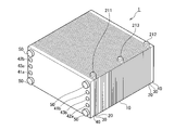
- FIG. 1A is an external perspective view showing an example of a laminated battery measured by the impedance measuring apparatus according to the first embodiment of the present invention.
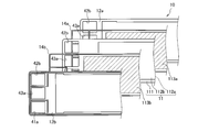
- FIG. 1B is an exploded view showing the structure of the power generation cell stacked on the stacked battery.
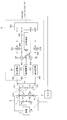
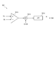
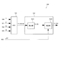
- FIG. 2 is a diagram showing a basic configuration of the impedance measuring apparatus.
- FIG. 3 is a diagram illustrating the DC blocking unit and the potential difference detection unit.
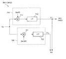
- FIG. 4 is a diagram illustrating a power supply unit that outputs an alternating current to the positive electrode and the negative electrode of the laminated battery.
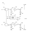
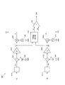
- FIG. 5 is a diagram illustrating details of an AC adjustment unit that adjusts the AC current of the positive electrode and the negative electrode, and a phase difference detection unit.
- FIG. 1A is an external perspective view showing an example of a laminated battery measured by the impedance measuring apparatus according to the first embodiment of the present invention.
- FIG. 1B is an exploded view showing the structure of the power generation cell stacked on the stacked battery.
- FIG. 2
- FIG. 6 is a diagram illustrating details of a positive-side detection circuit provided in the AC adjustment unit.
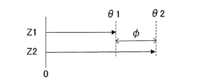
- FIG. 7 is a diagram showing the phase difference between the AC potential differences on the positive electrode side and the negative electrode side.
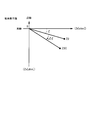
- FIG. 8 is a diagram illustrating an alternating current that leaks toward the load when a phase difference occurs.
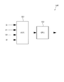
- FIG. 9 is a diagram illustrating details of a calculation unit that calculates the impedance of the laminated battery.
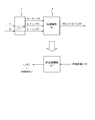
- FIG. 10 is a diagram illustrating an example of a technique for determining an allowable value for the phase difference.
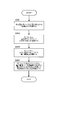
- FIG. 11 is a flowchart showing a method of equipotential control by the AC adjustment unit.
- FIG. 12 is a time chart when equipotential control is executed.
- FIG. 13 is a diagram illustrating the potentials of the positive electrode and the negative electrode when no phase difference occurs.
- FIG. 14 is a flowchart illustrating a detection method for detecting that the measurement state of the impedance measuring apparatus is defective based on the phase difference.
- FIG. 15 is a diagram illustrating a phase difference detection unit according to the second embodiment of the present invention.
- FIG. 16A is a diagram illustrating a method for determining that the current command values for the positive and negative power supply units have changed in opposite directions.
- FIG. 16B is a diagram illustrating a relationship between an absolute difference between each time change rate of the positive current command value and the negative current command value and a measurement state.
- FIG. 17 is a flowchart showing a diagnostic method for diagnosing the measurement state based on the difference between the positive and negative current command values.
- FIG. 18 is a diagram illustrating a phase difference detection unit according to the third embodiment of the present invention.
- FIG. 19 is a diagram illustrating details of the phase difference detection unit.
- FIG. 20 is a diagram illustrating a phase difference detection unit according to the fourth embodiment of the present invention.
- FIG. 21 is a diagram showing a phase correcting unit in the sixth embodiment of the present invention.
- FIG. 22 is a diagram illustrating an impedance measuring apparatus including a phase variable power supply unit.
- FIG. 23 is a diagram when the phase of the positive-side AC current is corrected to be delayed.
- FIG. 24 is a diagram showing an impedance measuring apparatus according to the seventh embodiment of the present invention.
- FIG. 25 is a diagram for explaining a technique for correcting a measurement error in the eighth embodiment of the present invention.
- FIG. 26 is a flowchart showing a correction processing method for correcting the internal resistance.
- FIG. 27 is a diagram showing the configuration of the calculation unit in the ninth embodiment of the present invention.
- FIG. 28 is a diagram illustrating an example of the phase difference of the AC potential difference between the positive electrode side and the negative electrode side.
- FIG. 29A is a diagram illustrating an example of impedance phases on the positive electrode side and the negative electrode side.
- FIG. 29B is a diagram illustrating an example of impedance phases on the positive electrode side and the negative electrode side.
- FIG. 29A is a diagram illustrating an example of impedance phases on the positive electrode side and the negative electrode side.
- FIG. 29B is a diagram illustrating an example of impedance phases on the positive electrode side and the negative electrode
- FIG. 29C is a diagram illustrating an example of impedance phases on the positive electrode side and the negative electrode side.
- FIG. 30 is a diagram for explaining correction of an error caused by phase correction.
- FIG. 31 is a flowchart showing a method for correcting an error caused by phase correction.
- FIG. 32 is a diagram illustrating an example of the relationship between the correction amount and the corrected impedance.
- FIG. 33 is a diagram showing a configuration of a calculation unit in the tenth embodiment of the present invention.
- FIG. 34 is a flowchart showing another method for correcting an error caused by phase adjustment.
- FIG. 35 is a diagram for explaining the relationship between the frequency of the alternating current and the impedance.
- FIG. 36 is a diagram showing the configuration of the calculation unit in the eleventh embodiment of the present invention.
- FIG. 37 is a diagram showing an impedance measuring apparatus according to the twelfth embodiment of the present invention.
- FIG. 1A is an external perspective view showing an example of a laminated battery measured by the impedance measuring apparatus according to the first embodiment of the present invention.
- FIG. 1A shows a fuel cell stack 1 in which a plurality of battery cells are stacked as an example of a stacked battery.
- the fuel cell stack 1 includes a plurality of power generation cells 10, a current collecting plate 20, an insulating plate 30, an end plate 40, and four tension rods 50.
- the power generation cell 10 is a so-called battery cell, and indicates one of the fuel cells stacked on the fuel cell stack 1.
- the power generation cell 10 generates an electromotive voltage of about 1 volt (V), for example.
- V volt
- the current collecting plates 20 are respectively disposed outside the stacked power generation cells 10.
- the current collecting plate 20 is formed of a gas impermeable conductive member, for example, dense carbon.
- the current collecting plate 20 includes a positive electrode terminal 211 and a negative electrode terminal 212.
- An intermediate point terminal 213 is provided between the positive terminal 211 and the negative terminal 212.
- the midpoint terminal 213 is connected to the battery cell 10 located in the middle of the power generation cells 10 stacked from the positive electrode terminal 211 to the negative electrode terminal 212. Note that the midpoint terminal 213 may be positioned away from the midpoint between the positive terminal 211 and the negative terminal 212. Electrons e ⁇ generated in the power generation cell 10 are taken out from the negative electrode terminal 212 of the fuel cell stack 1.
- the insulating plates 30 are respectively arranged outside the current collecting plate 20.
- the insulating plate 30 is formed of an insulating member such as rubber.
- the end plate 40 is disposed outside the insulating plate 30.
- the end plate 40 is made of a rigid metal material such as steel.
- One end plate 40 (the left front end plate 40 in FIG. 1A) has an anode supply port 41a, an anode discharge port 41b, a cathode supply port 42a, a cathode discharge port 42b, and a cooling water supply port 43a.
- a cooling water discharge port 43b is provided.
- the anode discharge port 41b, the cooling water discharge port 43b, and the cathode supply port 42a are provided on the right side in the drawing.
- the cathode discharge port 42b, the cooling water supply port 43a, and the anode supply port 41a are provided on the left side in the drawing.
- the tension rods 50 are arranged near the four corners of the end plate 40, respectively.
- the fuel cell stack 1 has a hole (not shown) penetrating therethrough.
- the tension rod 50 is inserted through the through hole.
- the tension rod 50 is formed of a rigid metal material such as steel.
- the tension rod 50 is insulated on the surface in order to prevent an electrical short circuit between the power generation cells 10.
- a nut (not shown because it is in the back) is screwed into the tension rod 50. The tension rod 50 and the nut tighten the fuel cell stack 1 in the stacking direction.
- a method of supplying hydrogen as the anode gas to the anode supply port 41a for example, a method of directly supplying hydrogen gas from a hydrogen storage device or a hydrogen-containing gas reformed by reforming a fuel containing hydrogen is supplied.
- the hydrogen storage device include a high-pressure gas tank, a liquefied hydrogen tank, and a hydrogen storage alloy tank.
- the fuel containing hydrogen include natural gas, methanol, and gasoline.
- Air is generally used as the cathode gas supplied to the cathode supply port 42a.
- FIG. 1B is an exploded view showing the structure of the power generation cells stacked on the fuel cell stack 1.
- an anode separator (anode bipolar plate) 12a and a cathode separator (cathode bipolar plate) 12b are arranged on both surfaces of a membrane electrode assembly (MEA) 11. Is the structure.
- MEA 11 has electrode catalyst layers 112 formed on both surfaces of an electrolyte membrane 111 made of an ion exchange membrane.
- a gas diffusion layer (gas diffusion layer: GDL) 113 is formed on the electrode catalyst layer 112.
- the electrode catalyst layer 112 is formed of, for example, carbon black particles on which platinum is supported.
- the GDL 113 is formed of a member having sufficient gas diffusibility and conductivity, for example, carbon fiber.
- the anode gas supplied from the anode supply port 41a flows through this GDL 113a, reacts with the anode electrode catalyst layer 112 (112a), and is discharged from the anode discharge port 41b.
- the cathode gas supplied from the cathode supply port 42a flows through this GDL 113b, reacts with the cathode electrode catalyst layer 112 (112b), and is discharged from the cathode discharge port 42b.
- the anode separator 12a is overlaid on one side of the MEA 11 (back side in FIG. 1B) via the GDL 113a and the seal 14a.
- the cathode separator 12b is overlaid on one side (the surface in FIG. 1B) of the MEA 11 via the GDL 113b and the seal 14b.
- the seal 14 (14a, 14b) is a rubber-like elastic material such as silicone rubber, ethylene propylene rubber (EPDM), or fluorine rubber.
- the anode separator 12a and the cathode separator 12b are formed by press-molding a metal separator base such as stainless steel so that a reaction gas channel is formed on one surface and alternately arranged with the reaction gas channel on the opposite surface. A cooling water flow path is formed. As shown in FIG. 1B, the anode separator 12a and the cathode separator 12b are overlapped to form a cooling water flow path.
- the MEA 11, the anode separator 12a, and the cathode separator 12b are respectively formed with holes 41a, 41b, 42a, 42b, 43a, 43b, which are stacked to be an anode supply port 41a, an anode discharge port 41b, and a cathode supply port.
- 42a, cathode discharge port 42b, cooling water supply port 43a and cooling water discharge port 43b are formed.
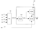
- FIG. 2 is a diagram showing a basic configuration of the impedance measuring apparatus 5 in the present embodiment.
- the impedance measuring device 5 measures the internal impedance of the fuel cell stack 1 mounted on the vehicle, for example.
- the fuel cell stack 1 is connected to a load 3 mounted on the vehicle.
- the load 3 is an electric motor or an auxiliary machine used for power generation of the fuel cell stack 1.
- the control unit (C / U) 6 controls the operation state of the load 3 and the operation state such as the power generation state and the wet state of the fuel cell stack 1 based on the measurement result measured by the impedance measuring device 5.
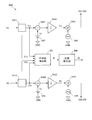
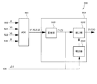
- the impedance measuring device 5 includes a positive-side DC blocking unit 511, a negative-side DC blocking unit 512, a midpoint DC blocking unit 513, a positive-side potential difference detecting unit 521, a negative-side potential difference detecting unit 522, and a positive-side power source unit. 531, a negative power supply unit 532, an AC adjustment unit 540, and a calculation unit 550.
- the positive side DC blocking unit 511 is connected to the positive terminal 211 of the fuel cell stack 1.
- the negative electrode side DC blocking unit 512 is connected to the negative electrode terminal 212 of the fuel cell stack 1.
- the midpoint DC blocking unit 513 is connected to the midpoint terminal 213 of the fuel cell stack 1.
- the DC blockers 511 to 513 block the DC signal but allow the AC signal to flow.
- the DC blockers 511 to 513 are, for example, capacitors or transformers. Note that the midpoint DC blocking unit 513 indicated by the broken line may not be provided.
- the positive electrode side potential difference detection unit 521 detects a potential difference between the AC potential Va generated at the positive electrode terminal 211 and the AC potential Vc generated at the midway terminal 213 (hereinafter referred to as “AC potential difference V1”).
- the positive potential difference detection unit 521 outputs a detection signal whose signal level changes according to the AC potential difference V1 to the calculation unit 550.
- the negative electrode side potential difference detection unit 522 detects a potential difference between the AC potential Vb generated at the negative electrode terminal 212 and the AC potential Vc generated at the midway terminal 213 (hereinafter referred to as “AC potential difference V2”).
- the negative electrode side potential difference detection unit 522 outputs a detection signal whose signal level changes according to the AC potential difference V2 to the calculation unit 550.
- the positive electrode side potential difference detection unit 521 and the negative electrode side potential difference detection unit 522 are realized by, for example, a differential amplifier (instrumentation amplifier).
- the positive power supply unit 531 is a first power supply unit that outputs an alternating current having a reference frequency fb.
- the positive power supply unit 531 is realized by a voltage-current conversion circuit such as an operational amplifier (OP amplifier).
- This voltage-current conversion circuit is a variable AC current source capable of adjusting the output current Io according to the input voltage Vi.
- the output current Io can be calculated by the input voltage Vi ⁇ proportional constant Rs without actually measuring the output current Io.
- the current Io can be obtained.
- the output of the voltage-current converter circuit is a current, the AC current flowing through the stacked cell group and the output current of the positive power supply unit 531 are in phase even if an element that causes a phase angle such as a capacitor is interposed in the current path. become. Further, it has the same phase as the input voltage Vi. Therefore, it is not necessary to consider the phase shift of the alternating current in the resistance calculation at the next stage, and the circuit is simple.
- the negative power supply unit 532 has the same configuration.
- the negative power supply unit 532 is a second power supply unit that outputs an alternating current having a reference frequency fb.
- the AC adjustment unit 540 adjusts the amplitude of the AC current output from at least one of the positive power supply unit 531 and the negative power supply unit 532 so that the positive AC potential Va matches the negative AC potential Vb. adjust.
- the AC adjustment unit 540 includes the amplitude of the AC current output from the positive power supply unit 531 and the negative electrode so that both the positive AC potential difference V1 and the negative AC potential difference V2 have predetermined values. Both the amplitude of the alternating current output from the side power supply unit 532 is increased or decreased.
- the AC adjustment unit 540 is realized by, for example, a PI (Proportional Integral) control circuit.
- the AC adjustment unit 540 outputs command signals for the positive power supply unit 531 and the negative power supply unit 532 to the calculation unit 550 as AC currents I1 and I2 output from the positive power supply unit 531 and the negative power supply unit 532, respectively. To do.
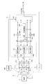
- the AC adjustment unit 540 includes a positive-side detection circuit 5411, a positive-side subtractor 5421, a positive-side integration circuit 5431, a positive-side multiplier 5441, a negative-side detection circuit 5412, a negative-side subtractor 5422, and a negative-side An integration circuit 5432 and a negative side multiplier 5442 are included.
- the AC adjustment unit 540 includes a reference power source 545 and an AC signal source 546.
- the reference power source 545 outputs a potential difference (hereinafter referred to as “reference voltage Vs”) determined based on zero (0) V.
- the reference voltage Vs is a value determined in advance in order to make the positive electrode side AC potential difference V1 coincide with the positive electrode side AC potential difference V2.
- the AC signal source 546 is an oscillation source that oscillates an AC signal having the reference frequency fb.
- the reference frequency fb is set to a predetermined frequency suitable for measuring the internal impedance of the fuel cell stack 1.
- the positive-side detector circuit 5411 removes unnecessary signals from the alternating-current potential Va generated in the signal line connecting the direct-current blocking unit 511 and the positive-side power supply unit 531, and the alternating-current potential Va is proportional to the amplitude of the alternating-current potential Va. Converted to a direct current signal. For example, the positive detector circuit 5411 outputs an average value or an effective value of the AC potential difference V1 as a DC signal.
- the positive detection circuit 5411 is realized by a synchronous detection circuit.
- the positive detection circuit 5411 extracts the real axis component V1r and the imaginary axis component V1x of the AC potential difference V1 from the AC potential Va generated at the output terminal of the positive power supply unit 531. Then, the positive electrode side detection circuit 5411 outputs the real axis component V1r of the AC potential difference V1 to the positive electrode side subtracter 5421.
- the actual axis component V1r is a value corresponding to an average value or an effective value of the AC potential difference V1, and the value of the actual axis component V1r decreases as the phase of the AC potential difference V1 is delayed with respect to the AC current I1. Details of the positive detector circuit 5411 will be described later with reference to FIG.
- the positive-side subtractor 5421 subtracts the reference voltage Vs from the real-axis component V1r of the alternating-current potential difference V1 output from the positive-side detection circuit 5411, thereby obtaining a difference signal indicating the deviation width of the real-axis component V1r from the reference voltage Vs. calculate. For example, the signal level of the differential signal increases as the deviation width from the reference voltage Vs increases.
- the positive side integration circuit 5431 integrates the difference signal output from the positive side subtractor 5421 to average or adjust the sensitivity of the difference signal. Then, the positive side integration circuit 5431 outputs the integrated difference signal to the positive side multiplier 5451 as the positive side current command value I1c.
- the positive-side multiplier 5441 multiplies the alternating-current signal output from the alternating-current signal source 546 with the reference frequency fb by the positive-side current command value I1c, thereby converging the alternating-current potential difference V1 to the reference voltage Vs. Is output. As the positive-side current command value I1c increases by the positive-side multiplier 5441, the amplitude of the command signal increases.
- the positive-side multiplier 5451 outputs the command signal of the alternating current I1 to the positive-side power supply unit 531.
- An AC voltage signal Vi input to the positive power supply unit 531 as a command signal for the AC current I1 is converted into an AC current signal Io by the positive power supply unit 531 and output to the positive terminal 211 of the fuel cell stack 1.
- the negative-polarity detection circuit 5412, the negative-polarity subtractor 5422, the negative-polarity integration circuit 5432, and the negative-polarity multiplier 5442 are a positive-polarity detection circuit 5411, a positive-polarity subtracter 5421, a positive-polarity integration circuit 5431, and a positive-polarity multiplication, respectively.
- the configuration is basically the same as that of the instrument 5441.
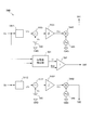
- FIG. 6 is a diagram illustrating an example of the configuration of the positive-side detection circuit 5411.
- the positive polarity detection circuit 5411 includes an in-phase component extraction unit 710 and a quadrature component extraction unit 720.
- the in-phase component extraction unit 710 multiplies the AC potential Va from the positive power supply unit 531 by the in-phase signal Sin (0) for detecting the same frequency component as the AC current I1 output from the positive power supply unit 531. Thus, the real axis component V1r of the AC potential difference V1 is extracted.
- the in-phase signal Sin (0) is an AC signal having a reference frequency fb, and is an AC signal having the same phase as the AC current output from the positive power supply unit 531.
- the in-phase signal Sin (0) is input from the AC signal source 546 to the in-phase component extraction unit 710, for example.
- the in-phase component extraction unit 710 includes an in-phase multiplication unit 711 and an in-phase low-pass filter 712.
- the in-phase multiplication unit 711 multiplies the positive-side AC potential Va by the in-phase signal Sin (0).
- the in-phase multiplier 711 outputs an in-phase AC signal corresponding to the degree of coincidence between the waveform of the AC potential Va and the waveform of the in-phase signal Sin (0). For example, when the phase of the AC potential Va and the in-phase signal Sin (0) completely match, an in-phase AC signal having a full-wave rectified waveform is output. Further, the greater the degree of coincidence between the waveform of the AC potential Va and the in-phase signal Sin (0), the greater the real axis component V1r.
- the in-phase low-pass filter 712 detects the DC component of the in-phase AC signal as the real axis component V1r.
- the in-phase low-pass filter 712 is realized by a low-pass filter (LPF) that removes the AC component of the in-phase AC signal, that is, the high-frequency region component and passes the DC component of the in-phase AC signal.
- LPF low-pass filter
- the in-phase AC signal smoothed by the in-phase low-pass filter 712 is input to the positive side subtractor 5421 and the phase difference detection unit 561.
- the in-phase component extraction unit 710 rectifies the AC potential difference Va by multiplying the AC potential Va by the in-phase signal Sin (0) having the same phase as the output current I1 of the positive power source unit 531.
- the in-phase signal Sin (0) having the same phase as the output current I1 of the positive power source unit 531.
- an AC signal having the same frequency and the same phase as the output current I1 of the positive power supply unit 531 can be extracted from the AC potential Va as the real axis component V1r. For this reason, even if AC potential Va is buried in noise, real axis component V1r can be detected reliably.
- the orthogonal component extraction unit 720 is provided to detect a phase difference between the AC potential Va and the AC potential Vb.
- the quadrature component extraction unit 720 multiplies the ac potential Va by a quadrature signal Sin (90) for detecting a component whose phase is orthogonal at the same frequency as the output current I1 of the positive-side power supply unit 531, thereby obtaining the ac potential difference V1.
- the imaginary axis component V1x is extracted.
- the quadrature signal Sin (90) is an AC signal having a reference frequency fb, and the phase is advanced by 90 degrees with respect to the output current of the positive power supply unit 531 and the AC signal has the same amplitude as the in-phase signal Sin (0). Signal.
- the quadrature signal Sin (90) is input to the quadrature component extraction unit 720 by rotating the phase of the AC signal source 546 by 90 degrees, for example.
- the orthogonal component extraction unit 720 includes an orthogonal multiplication unit 721 and an orthogonal low-pass filter 722.
- the orthogonal multiplication unit 721 multiplies the AC potential Va by the orthogonal signal Sin (90). As a result, the orthogonal multiplication unit 721 outputs an orthogonal AC signal corresponding to the degree of coincidence between the waveform of the AC potential Va and the waveform of the orthogonal signal Sin (90).
- the orthogonal low-pass filter 722 detects the DC component of the orthogonal AC signal as an imaginary axis component V1x.
- the orthogonal low-pass filter 722 is realized by a low-pass filter that removes the AC component of the orthogonal AC signal, that is, the high-frequency region component and passes the DC component of the orthogonal AC signal.
- the orthogonal AC signal smoothed by the orthogonal low-pass filter 722 is input to the phase difference detection unit 561 as the imaginary axis component V1x of the detection signal.
- the quadrature component extraction unit 720 multiplies the quadrature signal Sin (90) by the AC potential Va and rectifies it. As a result, it is possible to extract only the AC signal whose phase is advanced by 90 degrees at the same frequency as the output current of the positive power supply unit 531 as the imaginary axis component V1x from the AC potential Va. For this reason, even if the AC potential Va is buried in noise, the imaginary axis component V1x can be reliably detected.
- the positive electrode side detection circuit 5411 detects the real axis component V1r and the imaginary axis component V1x of the AC potential difference V1 based on the AC potential Va.
- the positive detector circuit 5411 outputs the real axis component V1r to the positive subtractor 5421 in order to feed back the amplitude of the alternating current output from the positive power source 531.
- the positive detector circuit 5411 outputs the imaginary axis component V1x of the AC potential difference V1 to the phase difference detection unit 561 in order to detect the phase difference of the AC potential generated at the positive electrode terminal 211 and the negative electrode terminal 212 of the fuel cell stack 1.
- the vector value V1p of the AC potential difference V1 is obtained from the AC potential Va and output to the positive side subtractor 5421. You may make it do. Specifically, as shown in the following equation, the vector value Vp1 is obtained by calculating the square root of the sum of the square value of the real axis component V1r and the square value of the imaginary axis component V1x.
- the real axis component V1r and the imaginary axis component V1x of the AC potential difference V1 are extracted from the AC potential Va generated at the output terminal of the positive power supply unit 531 .
- the real axis component V1r and the imaginary axis component V1x of the AC potential difference V1 may be extracted from the output signal of the positive potential difference detection unit 521 instead of the AC potential Va.
- the real axis component V1r of the AC potential difference V1 can be detected by multiplying the detection signal indicating the AC potential difference V1 output from the positive electrode side potential difference detection unit 521 by the in-phase signal Sin (0).
- the AC adjustment unit 540 adjusts the amplitude of the AC current output from the positive power supply unit 531 so that the real axis component V1r of the AC potential difference V1 extracted from the AC potential Va becomes the reference voltage Vs. Similarly, the AC adjustment unit 540 adjusts the amplitude of the AC current output from the negative power supply unit 532 so that the real axis component V2r of the AC potential difference V2 extracted from the AC potential Vb becomes the reference voltage Vs.
- the power generation cell 10 equivalently has a capacitance component in addition to the resistance component, the equipotential control is correctly performed by the capacitance component synthesized inside the fuel cell stack 1. It may stop functioning. The case where equipotential control does not function correctly will be described below.
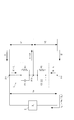
- the equivalent circuit of the fuel cell stack 1 has a positive-side internal resistance R1 and a negative-side internal resistance R2, and a positive-side capacitance C1 and a negative-side capacitance C2 in parallel.
- R1 and R2 positive-side internal resistance
- C1 and C2 positive-side capacitance C1 and a negative-side capacitance C2 in parallel.
- Can be represented as a circuit connected to The inventors have found that the electrostatic capacitance C1 and the electrostatic capacitance C2 vary greatly depending on the operating state of the fuel cell stack 1, the operating state of the load 3, and the like.
- the gas concentrations of the anode gas and the cathode gas in the fuel cell stack 1 rises. Accordingly, the electrostatic capacitance C1 and the electrostatic capacitance C2 change, and the phase difference ⁇ between the detection signal indicating the AC potential difference V1 and the detection signal indicating the AC potential difference V2 increases.
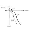
- FIG. 7 is a diagram for explaining a phase shift between detection signals indicating AC potential differences V1 and V2.
- FIG. 7 shows a vector 611 representing the AC potential difference V1, a vector 612 representing the AC potential difference V2, and a difference vector 613 representing the potential difference Ve obtained by subtracting the vector 612 from the vector 611. Further, the amplitude of the detection signal is indicated by a dashed line.
- the horizontal axis indicates the real axis components of the AC potential differences V1 and V2 with reference to the AC currents I1 and I2, and the vertical axis indicates the imaginary axis components of the AC potential differences V1 and V2.
- the magnitudes of the vector 611 and the vector 612 are adjusted to the reference voltage Vs, and the reactance of the capacitance C2 becomes smaller than the capacitance C1 depending on the operating state of the fuel cell stack 1 or the load 3.
- Vector 611 and vector 612 are shown.
- the vector 611 is delayed by the phase angle ⁇ 1 with respect to the alternating current I1 due to the capacitance C1.
- the real axis component V1r of the vector 611 is a value obtained by multiplying the alternating current I1 and the internal resistance R1.
- the imaginary axis component V1x is a value obtained by multiplying the alternating current I1 and the capacitive reactance X1c.
- the capacitive reactance X1c is a reciprocal of a value obtained by multiplying the angular velocity ⁇ of the alternating current I1 by the capacitance C1.
- the vector 612 is delayed by the phase angle ⁇ 2 with respect to the alternating current I2 due to the capacitance C2.
- the real axis component V2r of the vector 612 is a value obtained by multiplying the alternating current I2 and the internal resistance R2.
- the imaginary axis component V2x is a value obtained by multiplying the alternating current I2 and the capacitive reactance X2c.
- the capacitive reactance X1c is a reciprocal of a value obtained by multiplying the angular velocity ⁇ of the alternating current I2 by the capacitance C2.
- the anode outlet 41b is provided on the positive electrode terminal 211 side as shown in FIG.
- the impurity gas is likely to accumulate near the anode discharge port 41b, that is, on the positive electrode terminal 211 side.
- the hydrogen concentration of the power generation cell group stacked from the positive electrode terminal 211 to the midpoint terminal 213 may be lower than the hydrogen concentration of the power generation cell group stacked from the midpoint terminal 213 to the negative electrode terminal 212.
- the electrostatic capacity component of the power generation cell 10 with respect to the alternating current decreases, so the electrostatic capacity C1 becomes smaller than the electrostatic capacity C2.
- the phase angle ⁇ 1 of the vector 611 is smaller than the phase angle ⁇ 2 of the vector 612, and there is a phase difference between the detection signal indicating the AC potential difference V1 and the detection signal indicating the AC potential difference V2. ⁇ is generated.
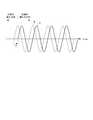
- FIG. 8 is a conceptual diagram showing an alternating current leaking to the load 3 when a phase difference ⁇ occurs between the detection signals indicating the alternating potential differences V1 and V2.
- FIG. 8A is a diagram showing waveforms of the AC potential difference V1 of the vector 611 and the AC potential difference V2 of the vector 612 shown in FIG.
- FIG. 8B is a diagram illustrating a waveform of the AC potential difference Ve of the difference vector 613.
- the vertical axis indicates the amplitude
- the horizontal axis is a common time axis.
- a phase difference ⁇ between the phase angle ⁇ 1 of the vector 611 and the phase angle ⁇ 2 of the vector 612 is generated between the AC potential difference V1 and the AC potential difference V2.
- an AC potential difference Ve is generated between the positive terminal 211 and the negative terminal 212 of the fuel cell stack 1 as shown in FIG.
- the electrostatic capacity C1 or the electrostatic capacity C2 varies depending on the operating state of the fuel cell stack 1, and the phase difference ⁇ is generated between the detection signals of the AC potential differences V1 and V2, the internal resistances R1 and R2 The error included in the measurement result may exceed the allowable range.
- the signal levels of the detection signals output from the positive electrode side detection circuit 5411 and the negative electrode side detection circuit 5412 both show a constant value by the equipotential control. Therefore, the impedance measurement is performed without detecting that the measurement state of the impedance measuring device 5 is defective.
- the phase difference of the AC potential supplied to both the positive electrode terminal 211 and the negative electrode terminal 212 due to the electrostatic capacitance component of the fuel cell stack 1 is detected, and the impedance is determined based on the phase difference. It is diagnosed whether or not the measurement state of measuring is defective.
- the first embodiment is realized by the phase difference detection unit 561 and the determination circuit 562 shown in FIG.
- the phase difference detection unit 561 is a circuit that detects the phase difference between the AC potential generated at the positive terminal 211 and the AC potential generated at the negative terminal 212 of the fuel cell stack 1.
- the phase difference detection unit 561 detects the AC potential difference V1 and the AC potential difference based on the detection signal of the AC potential difference V1 output from the positive electrode side detection circuit 5411 and the detection signal of the AC potential difference V2 output from the negative electrode side detection circuit 5412. The phase difference from V2 is calculated.
- the phase difference detection unit 561 uses the real axis component V1r and the imaginary axis component V1x of the AC potential difference V1 output from the positive electrode side detection circuit 5411 according to the following formula to determine the phase angle ⁇ 1 of the AC potential difference V1. Calculate.
- phase difference detection unit 561 calculates the phase angle ⁇ 2 of the AC potential difference V2 using the real axis component V2r and the imaginary axis component V2x of the AC potential difference V2 output from the negative electrode side detection circuit 5412 according to the following equation.
- the phase difference detection unit 561 calculates a value obtained by subtracting the phase angle ⁇ 2 of the AC potential difference V2 from the phase angle ⁇ 1 of the AC potential difference V1 between the AC potential generated at the positive terminal 211 and the AC potential generated at the negative terminal as shown in the following equation. Is calculated as a phase difference ⁇ between them and output to the determination circuit 562.
- the determination circuit 562 compares the phase difference ⁇ output from the phase difference detection unit 561 with a predetermined allowable value Th1, and determines whether the measurement state in which the internal resistances R1 and R2 are measured is defective. Diagnose.
- the allowable value Th1 of the phase difference ⁇ is an upper limit value within a range in which a measurement error can be allowed, that is, a threshold value, and is set by experimental data or the like. A method for determining the allowable value Th1 will be described later with reference to FIG.
- the determination circuit 562 determines that the equipotential control is poor due to the phase difference ⁇ .
- a determination signal of H (High) level indicating that the measurement state is defective is generated.
- the determination circuit 562 when the phase difference ⁇ is smaller than the allowable value Th1, the determination circuit 562 generates an L (Low) level determination signal indicating that the measurement state is not defective. Then, the determination circuit 562 outputs the generated determination signal to the controller unit 6 or the arithmetic unit 550.
- the calculation unit 550 includes detection signals indicating the AC potential differences V1 and V2 output from the positive electrode side potential difference detection unit 521 and the negative electrode side potential difference detection unit 522, an AC current I1 for the positive electrode side power supply unit 531 and the negative electrode side power supply unit 532, and The I2 command signal is input. In other words, the calculation unit 550 acquires the detection values of the alternating currents I1 and I2 and the detection values of the AC potential differences V1 and V2.
- the calculation unit 550 calculates the internal impedance of the fuel cell stack 1 based on the AC potential differences V1 and V2 and the AC currents I1 and I2.
- the calculation unit 550 calculates a real axis component and an imaginary axis component of the AC potential difference V1 based on the detection signal from the positive electrode side potential difference detection unit 521, and AC based on the detection signal from the negative electrode side potential difference detection unit 522.
- the real axis component and the imaginary axis component of the potential difference V2 are calculated.
- the calculation unit 550 calculates the internal resistance R1 by dividing the real axis component of the AC potential difference V1 by the AC current I1, and internally calculates the internal axis component by dividing the real axis component of the AC potential difference V2 by the AC current I2.
- the resistance R2 is calculated.
- the calculation unit 550 may calculate the capacitances C1 and C2 using the imaginary axis components of the AC potential differences V1 and V2.
- the calculation unit 550 obtains an average value or an effective value of the AC potential differences V1 and V2 based on detection signals from the positive electrode side potential difference detection unit 521 and the negative electrode side potential difference detection unit 522, and generates a command signal from the AC adjustment unit 540. Based on this, the average value or the effective value of the alternating currents I1 and I2 may be obtained. Then, the calculation unit 550 calculates the internal resistance R1 by dividing the average value or effective value of the AC potential difference V1 by the average value or effective value of the AC current I1, and calculates the average value or effective value of the AC potential difference V2 as the AC current. The internal resistance R1 is calculated by dividing by the average value or effective value of I2.
- the calculation unit 550 includes an AD (Analog Digital) converter 551 and a microcomputer chip 552.
- AD Analog Digital
- the AD converter 551 converts the alternating current command signals (I1, I2) and the alternating potential difference detection signals (V1, V2), which are analog signals, into digital numerical signals and transfers them to the microcomputer chip 552.
- the microcomputer chip 552 stores a program for calculating the internal resistance Rn and the internal resistance R of the entire fuel cell stack 1 in advance.
- the microcomputer chip 552 sequentially calculates at a predetermined minute time interval or outputs a calculation result in response to a request from the controller unit 6.
- the internal resistance Rn and the internal resistance R of the entire fuel cell stack 1 are calculated by the following equations.
- the arithmetic unit 550 may be realized by an analog arithmetic circuit using an analog arithmetic IC. According to the analog arithmetic circuit, it is possible to output a temporally continuous change in resistance value to the controller unit 6.
- the controller unit 6 acquires the internal resistance R output from the calculation unit 550 as the impedance measurement result, and acquires the determination signal output from the determination circuit 562 as the measurement state determination result.
- the determination signal is input to the controller unit 6 via the arithmetic unit 550, for example.
- the controller unit 6 controls the operating state of the fuel cell stack 1 according to the measurement result of the internal resistance R. For example, when the internal resistance R is high, the controller unit 6 determines that the electrolyte membrane of the fuel cell stack 1 is in a dry state, and reduces the flow rate of the cathode gas supplied to the fuel cell stack 1. Thereby, the amount of water taken out from the fuel cell stack 1 can be reduced.
- the controller unit 6 when the balance between the electrostatic capacitance C1 and the electrostatic capacitance C2 is lost and the phase difference ⁇ between the AC potential differences V1 and V2 becomes large and the determination signal becomes H level, the controller unit 6 has a poor measurement state. And the measurement result of the internal resistance R is discarded.
- the controller unit 6 sets the internal resistance R calculated by the calculation unit 550 as a measurement result before the determination signal is switched from the L level to the H level, and fixes the measurement result until the determination signal returns to the L level.
- the controller unit 6 records the resistance value in a memory (not shown) in time series and holds the resistance value in the memory for a specific period.
- the controller unit 6 calculates a fixed value used as a measurement result based on the plurality of resistance values held in the memory when the determination signal is switched from the L level to the H level.
- the fixed value for example, an average value obtained by averaging a plurality of resistance values held in the memory, or the latest value recorded last in the memory among the plurality of resistance values is used.
- the controller unit 6 has a plurality of control blocks for controlling the cathode gas supply flow rate, the anode gas supply flow rate, the cooling water temperature, etc. of the fuel cell stack 1, and the internal resistance R required for each control block is assumed.
- the handling of the measurement result can be changed according to the code added to the measurement data.
- the phase difference ⁇ detected by the phase difference detection unit 561 may be directly input to the controller unit 6 so that the controller unit 6 diagnoses whether or not the measurement state of the impedance measuring device 5 is defective.
- the phase difference ⁇ is input to the calculation unit 550, and the calculation unit 550 diagnoses the measurement state.
- the calculation result is discarded and the measurement result before the determination is made that the measurement is defective. You may make it output to the controller unit 6.
- phase difference detection unit 561 calculates the phase difference ⁇ between the AC potential difference V1 and the AC potential difference V2
- the calculation unit 550 may determine the phase difference ⁇ .
- the real axis component V1r and the imaginary axis component V1x output from the positive electrode side detection circuit 5411 and the real axis component V2r and the imaginary axis component V2x output from the negative electrode side detection circuit 5412 are input to the calculation unit 550.
- the calculation unit 550 calculates the equations (2) to (4) to obtain the phase difference ⁇ .
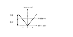
- the example in which the phase difference ⁇ between the AC potential difference V1 and the AC potential difference V2 is used to detect whether the measurement state is defective has been described.
- the imaginary axis component V1x on the positive electrode side and the negative electrode side The difference ⁇ Vx from the imaginary axis component V2x may be used.
- the phase difference ⁇ between the AC potential difference V1 and the AC potential difference V2 is proportional to the difference ⁇ Vx obtained by subtracting the imaginary axis component V2x on the negative electrode side from the imaginary axis component V1x on the positive electrode side, as shown in the following equation.
- the imaginary axis component difference ⁇ Vx increases as the phase difference ⁇ of the detection signal increases.
- the allowable value is an upper limit value within a range in which an impedance measurement error can be allowed, and is set according to system design from experimental data or the like.
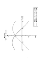
- FIG. 10 is a diagram for explaining an example of a setting method for setting an allowable value for the phase difference ⁇ used in the determination circuit 562.
- the transfer function G is obtained by modeling the circuit configuration of the impedance measuring device 5.
- the output of the transfer function G with respect to these inputs is a value obtained by adding the measurement error E ( ⁇ ) to the internal resistance R (Vs, I1, I2).
- the allowable value E ( ⁇ ) of the measurement error determined according to the use of the measurement result is substituted into the reverse transfer function G ⁇ 1 , whereby the leakage current I L ( ⁇ ) is calculated, and this calculated value is used as a determination value for determining whether or not the measurement state is defective.
- An allowable value Th1 of the phase difference ⁇ is determined by this determination value.
- requires the transfer function G and sets allowable value Th1 was demonstrated here, it is not restricted to this.
- the relationship between the phase difference ⁇ detected by the phase difference detection unit 561 and the measurement error E ( ⁇ ) by the impedance measuring device 5 is obtained in advance through experiments, and the allowable measurement error E ( ⁇ ) is obtained from the result. May be set as the allowable value Th1.
- the allowable value Th1 is fixed to a predetermined value.
- the allowable value Th1 may be changed as appropriate in consideration of such deterioration factors.
- a data table or a function equation indicating the relationship between the integrated value of the time when the fuel cell stack 1 is used and the allowable value of the phase difference ⁇ is stored in the impedance measuring device 5 in advance, and the data table is used.
- the allowable value Th1 is changed when the impedance measuring apparatus 5 is started.
- the allowable value Th1 may be set or corrected.
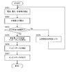
- FIG. 11 is a flowchart illustrating an example of a control method when the control performed by the AC adjustment unit 540 is realized by a controller.
- step S1 the controller determines whether or not the positive AC potential Va is greater than a predetermined value. If the determination result is negative, the controller proceeds to step S2, and if the determination result is positive, the controller proceeds to step S3.
- step S2 the controller determines whether or not the positive AC potential Va is smaller than a predetermined value. If the determination result is negative, the controller proceeds to step S4, and if the determination result is positive, the controller proceeds to step S5.
- step S3 the controller decreases the output of the positive power supply unit 531. That is, the controller decreases the amplitude of the alternating current I1. As a result, the positive AC potential Va decreases.
- step S4 the controller maintains the output of the positive power supply unit 531. As a result, the positive AC potential Va is maintained.
- step S5 the controller increases the output of the positive power supply unit 531. As a result, the positive AC potential Va increases.
- step S6 the controller determines whether or not the negative AC potential Vb is greater than a predetermined value. If the determination result is negative, the controller proceeds to step S7, and if the determination result is positive, the controller proceeds to step S8.
- step S7 the controller determines whether or not the negative electrode AC potential Vb is smaller than a predetermined value. If the determination result is negative, the controller proceeds to step S9. If the determination result is positive, the controller proceeds to step S10.
- step S8 the controller decreases the output of the negative power source unit 532. As a result, the negative AC potential Vb decreases.
- step S9 the controller maintains the output of the negative power supply unit 532. As a result, the negative AC potential Vb is maintained.
- step S10 the controller increases the output of the negative power source unit 532. This increases the negative AC potential Vb.
- step S11 the controller determines whether or not the AC potential Va and the AC potential Vb are predetermined values. If the determination result is positive, the controller proceeds to step S12. If the determination result is negative, the controller exits the process.
- step S12 the controller calculates the internal resistance value based on the above equations (5-1) and (5-2).
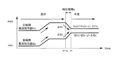
- FIG. 12 is a time chart when the controller executes control of the impedance measuring device 5. Note that step numbers are also shown so that the correspondence with the flowchart is easy to understand.
- the internal resistance value R1 on the positive electrode side is higher than the internal resistance value R2 on the negative electrode side (FIG. 12 (A)).
- the controller starts control.
- the controller repeats steps S1, S2, S4, S6, S8, S11, and S12.
- the negative side AC current I2 is lowered as the negative side internal resistance value R2 increases, so the negative side AC potential Vb is maintained at the same level as the positive side AC potential Va. Therefore, the internal resistance R is calculated even in this state.
- the internal resistance value R2 on the negative electrode side coincides with the internal resistance value R1 on the positive electrode side (FIG. 12A).
- the controller repeats steps S1, S2, S4, S6, S7, S9, S11, and S12. By processing in this way, the positive side AC potential Va and the negative side AC potential Vb are maintained at the same level (FIG. 12C), and the internal resistance R is calculated.
- FIG. 13 is a diagram illustrating the state of the positive electrode potential generated at the positive electrode terminal 211 and the negative electrode potential generated at the negative electrode terminal 212 of the fuel cell stack 1 when the measurement state of the impedance measuring device 5 is good.
- a potential difference V3 is generated between the positive terminal 211 and the negative terminal 212.
- the impedance measuring device 5 Before the impedance measuring device 5 is activated (ON), the positive electrode potential and the negative electrode potential are constant, and a DC voltage is supplied to the load 3.
- the impedance measuring device 5 is activated and the alternating currents I1 and I2 are output from the positive power supply unit 531 and the negative power supply unit 532, the alternating current potential Va is superimposed on the positive potential and the alternating potential Vb is superimposed on the negative potential. Is done.
- the positive power supply unit 531 and the negative power supply unit 532 adjust the amplitudes of the AC currents I1 and I2 and output them.
- the AC adjustment unit 540 determines the difference (V1 ⁇ V2) between the AC potential difference V1 on the positive electrode side of the fuel cell stack 1 and the AC potential difference V2 on the negative electrode side, that is, the difference (Va ⁇ Vb) between the AC potential Va and the AC potential Vb. Is adjusted so that the positive power supply unit 531 and the negative power supply unit 532 are always reduced.
- the calculation unit 550 includes AC potential differences V1 and V2 output from the positive electrode side potential difference detection unit 521 and the negative electrode side potential difference detection unit 522, and AC currents I1 and I2 output from the positive electrode side power supply unit 531 and the negative electrode side power supply unit 532. And apply Ohm's law. As a result, the calculation unit 550 calculates the internal resistance R1 on the positive electrode side and the internal resistance R2 on the negative electrode side of the fuel cell stack 1.
- the AC potential of the positive electrode terminal 211 and the negative electrode terminal 212 is the same, even if the load device 3 such as a traveling motor is connected to the positive electrode terminal 211 and the negative electrode terminal 212, AC current leaks to the load device 3. Can be suppressed.
- the alternating current values I1 and I2 flowing through the fuel cell stack 1 that is the measurement target of the internal resistance substantially coincide with the alternating current values output from the positive power supply unit 531 and the negative power supply unit 532. Therefore, the internal resistance value R1 and the internal resistance value R2 of the fuel cell stack 1 can be accurately obtained from the alternating current values output from the positive power supply unit 531 and the negative power supply unit 532. Furthermore, the internal resistance value R of the entire fuel cell stack 1 can be accurately measured based on the internal resistance value R1 and the internal resistance value R2 of the operating fuel cell stack 1 regardless of the state of the load device 3. Further, since the positive electrode side power supply unit 531 and the negative electrode side power supply unit 532 are used, the internal resistance R can be measured even when the fuel cell stack 1 is stopped.
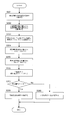
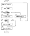
- FIG. 14 is a flowchart showing an example of a processing procedure of a failure detection method for detecting whether or not the measurement state of the impedance measuring device 5 is defective.
- step S101 the positive-side detection circuit 5411 decomposes the positive-side AC potential difference V1 into the real axis component V1r and the imaginary axis component V1x, and outputs the real axis component V1r and the imaginary axis component V1x to the phase difference detection unit 561.
- step S102 the phase difference detection unit 561 calculates the phase angle ⁇ 1 of the AC potential difference V1 with respect to the AC current I1 based on the real axis component V1r and the imaginary axis component V1x of the AC potential difference V1 according to Expression (2).
- step S103 the negative-side detection circuit 5412 decomposes the negative-side AC potential difference V2 into the real axis component V2r and the imaginary axis component V2x, and outputs the real axis component V1r and the imaginary axis component V1c to the phase difference detection unit 561.
- step S104 the phase difference detection unit 561 calculates the phase angle ⁇ 2 of the AC potential difference V2 with respect to the AC current I2 based on the real axis component V2r and the imaginary axis component V2x of the AC potential difference V2 according to Expression (3).
- step S105 the phase difference detection unit 561 calculates a phase difference between the AC potential difference V1 and the AC potential difference V2 by subtracting the phase angle ⁇ 2 of the AC potential difference V2 from the phase angle ⁇ 1 of the AC potential difference V1 according to the equation (4). The result is output to the determination circuit 562 as ⁇ .
- step S106 the determination circuit 562 determines whether or not the phase difference ⁇ is smaller than the allowable value Th1.
- the determination circuit 562 determines that the measurement state of the internal resistance R is good when the phase difference ⁇ is smaller than the allowable value Th1.
- the determination circuit 562 determines that the measurement state is defective.
- the determination circuit 562 outputs the determination result to the calculation unit 550.
- the calculation unit 550 When it is determined in step S107 that the measurement state of the internal resistance R is good, the calculation unit 550 outputs the resistance value calculated in step S12 illustrated in FIG. 11 to the controller unit 6 as a measurement result. . Note that the calculation unit 550 may generate and output measurement data indicating the resistance value calculated in step S12, the determination result, and the phase difference ⁇ .
- step S108 when it is determined in step S108 that the measurement state of the internal resistance R is defective, the arithmetic unit 550 executes measurement result processing associated with the measurement defect.
- the calculation unit 550 discards the resistance value calculated in step S12, and outputs the resistance value before being determined as a measurement failure to the controller unit 6 for a predetermined time, for example, as a measurement result.
- the calculating part 550 may produce
- step S107 or S108 a series of processing procedures of the defect detection method based on the phase difference ⁇ ends.
- the impedance of the fuel cell stack 1, which is an example of a stacked battery is measured.
- the impedance measuring device 5 includes a positive power source 531 that outputs an alternating current having a predetermined reference frequency fb to the positive terminal 211 of the fuel cell stack 1 and a reference frequency fb to the negative terminal 212 of the fuel cell stack 1.
- a negative-side power supply unit 532 that outputs an alternating current of 2.
- a positive electrode side potential difference detection unit 521 that detects an AC potential difference V1 between the positive electrode terminal 211 and the midpoint terminal 213, and a negative electrode side potential difference detection unit that detects an AC potential difference V2 between the negative electrode terminal 212 and the midpoint terminal 213. 522.
- the AC adjustment unit 540 that adjusts the amplitude of the AC current output from at least one of the positive power supply unit 531 and the negative power supply unit 532 is adjusted so that the AC potential difference V1 and the AC potential difference V2 match.
- a calculation unit 550 that calculates impedance based on the AC current and the AC potential difference is provided.
- the impedance measuring device 5 includes a phase difference detection unit 561 that obtains a phase difference ⁇ between the AC potential generated at the positive electrode terminal 211 and the AC potential generated at the negative electrode terminal 212 or a parameter correlated with the phase difference ⁇ . Prepare. Based on the phase difference ⁇ or parameters related to the phase difference ⁇ , diagnostic processing for diagnosing whether the measurement state is defective, cancellation processing for discarding the measurement result, and fixing the measurement result to a predetermined value with high reliability One of the hold processes to be executed is executed.
- the measurement state diagnosis process, the measurement result cancellation process, and the hold process are executed. Therefore, the reliability of the measurement result can be ensured. Therefore, it is possible to maintain and improve the reliability of the measurement result when the measurement accuracy of the impedance measuring device 5 is reduced due to the variation in the capacitance component of the laminated battery.
- the capacitance component of the fuel cell stack 1 with respect to the AC signal of the reference frequency fb changes, and the difference between the positive electrode side capacitance C1 and the negative electrode side capacitance C2 is different. May be larger.
- the phase difference ⁇ between the AC potential generated at the positive electrode terminal 211 of the fuel cell stack 1 and the AC potential generated at the negative electrode terminal 212 becomes large, and the load 3 connected to the fuel cell stack 1 More AC current leaks out.
- the internal resistance R measured by the impedance measuring device 5 is used in the fuel cell system to control, for example, the wetness of the fuel cell stack 1. For this reason, in the state where the measurement accuracy of the internal resistance R is lowered, that is, the internal resistance R measured in a state where the measurement state of the impedance measuring device 5 is defective, the wetness of the fuel cell stack 1 can be appropriately controlled. It becomes difficult.
- the impedance measuring device 5 detects the phase difference ⁇ or a parameter related to the phase difference ⁇ , and the impedance measurement accuracy decreases due to variations in the capacitance C1 and the capacitance C2. Detecting that
- the impedance measuring device 5 determines that the measurement state is defective based on the phase difference ⁇
- the impedance measurement device 5 outputs a diagnosis result indicating that the measurement state is defective together with the measurement result.
- the measurement result may be discarded. Thereby, since the measurement result with low measurement accuracy and low reliability is not output, only the measurement result with high reliability can be reliably output to the controller unit 6 or the like.
- the measurement state is defective, past measurement results measured before being determined as defective may be output.
- the measurement result when the measurement state is good, that is, the measurement accuracy is high, for a system that must continue control using the measurement result.
- the measurement result can be output.
- the internal resistance R changes mainly depending on the wetness degree of the power generation cell 10
- the capacitance C1 or C2 is a gas state in the fuel cell stack 1, an operating state of the load 3, etc. It depends on. For this reason, it can be said that the correlation between the change in the internal resistance R and the change in the capacitance C is low.
- the resistance component R is likely to show a constant value. For this reason, when it is determined that the measurement state is defective based on the phase difference ⁇ , the reliability of the output result is improved by outputting the internal resistance value before being determined to be defective as the measurement result. It becomes possible.
- the first embodiment it is possible to maintain and improve the reliability of the measurement result with respect to the decrease in measurement accuracy in the impedance measuring apparatus 5 caused by the capacitance component of the laminated battery.
- the phase difference detection unit 561 is based on a detection signal indicating the AC potential difference V1 output from the positive electrode side detection circuit 5411 and a detection signal indicating the AC potential difference V2 output from the negative electrode side detection circuit 5412. To calculate the phase difference ⁇ .
- the impedance measuring device 5 determines that the measurement state is bad when the phase difference ⁇ is equal to or greater than the predetermined threshold Th1, and the measurement state is good when the phase difference ⁇ is smaller than the threshold Th1. It is determined that The threshold value Th1 is set according to an allowable range of measurement accuracy required from the system.
- the impedance measuring device 5 determines that the measurement state is good within the allowable range of measurement error, and the phase difference ⁇ is allowed. Only when the range is exceeded, it is determined that the measurement is defective. Thereby, according to the request
- the phase difference ⁇ is obtained using the detection signals output from the positive potential difference detection unit 521 and the negative potential detection unit 522 instead of the detection signals output from the positive detection circuit 5411 and the negative detection circuit 5412. You may do it.
- FIG. 15 is a diagram illustrating configurations of the AC adjustment unit 540 and the phase difference detection unit 571 according to the second embodiment of the present invention.
- phase difference detection unit 571 and a determination circuit 572 are provided instead of the phase difference detection unit 561 and the determination circuit 562 shown in FIG.
- the configuration other than the phase difference detection unit 571 and the determination circuit 572 is the same as the configuration of the AC adjustment unit 540 illustrated in FIG. 5, and thus description thereof is omitted here.
- the phase difference detector 571 receives the positive current command value I1c output from the positive integration circuit 5431 and the negative current command value I2c output from the negative integration circuit 5432.
- the phase difference detection unit 571 calculates the difference between the time variation ⁇ I1c of the positive current command value I1c and the time variation ⁇ I2c of the negative current command value I2c.
- the time change amounts ⁇ I1c and ⁇ I2c are time change rates, and indicate the amount by which the positive current command value I1c and the negative current command value I2c are increased or decreased within the same time.
- the difference between the positive current command value I1c and the negative current command value I2c is substantially constant, and the positive current command value I1c and the negative current Command value I2c changes in the same direction.
- the internal resistance R decreases, both the positive current command value I1c and the negative current command value I2c increase, and when the internal resistance R increases, the positive current command value I1c and the negative current command value I2c. Both decrease.
- the phase difference detection unit 571 uses the absolute value of the difference obtained by subtracting the time change amount ⁇ I2c from the time change amount ⁇ I1c as a parameter related to the phase difference ⁇ , and uses the positive current command value Ic1 and the negative current command value I2c. It is determined whether or not has changed in the opposite direction.
- FIG. 16A is a diagram illustrating a determination method for determining whether or not the positive-side current command value Ic1 and the negative-side current command value I2c have changed in opposite directions.
- FIG. 16B is a diagram showing the relationship between the absolute difference between the positive current command value I1c and the negative current command value I2c and the measurement state.
- the phase difference detection unit 571 acquires both the positive-side current command value I1c and the negative-side current command value I2c for each predetermined determination period (S seconds), and the positive-side current command value I1c and the negative-side Both current command values I2c are recorded in the memory 5711. At the same time, the phase difference detection unit 571 reads the positive-side current command value I1c and the negative-side current command value I2c recorded last time from the memory 5711.
- the phase difference detection unit 571 acquires the positive current command value I1c (n), and the previous positive current command value I1c (ns) acquired S seconds before time n from the memory 5711. read out.
- the acquisition time of the current command value is indicated by parentheses.
- phase difference detection unit 571 subtracts the positive-side current command value I1c (ns) acquired last time from the positive-side current command value I1c (n) acquired this time, as shown in the following equation.
- a time change amount ⁇ I1c of the command value I1c is calculated.
- the time variation ⁇ I1c is a negative (minus) value.
- phase difference detection unit 571 acquires the negative electrode current command value I2c (n) at time n, and reads the negative electrode current command value I2c (ns) acquired last time from the memory 5711. Then, the phase difference detecting unit 571 subtracts the negative electrode current command value I2c (ns) acquired last time from the negative electrode current command value I2c (n) acquired this time as A time change amount ⁇ I2c of the command value I2c is calculated.
- the time variation ⁇ I2c is a positive (plus) value.
- phase difference detection unit 571 subtracts the time change amount ⁇ I2c of the negative current command value I2c from the time change amount ⁇ I1c of the positive current command value I1c as shown in the following equation, and calculates the absolute value of the subtracted value. calculate.
- the absolute value of the difference between the time change amount ⁇ I1c and the time change amount ⁇ I2c is the largest value.
- the time change amount ⁇ I1c of the positive current command value I1c and the time change amount ⁇ I2c of the negative current command value I2c are The absolute value of the difference (absolute difference) increases.
- the determination circuit 572 has the absolute value of the difference between the time change amount ⁇ I1c of the positive-side current command value I1c and the time change amount ⁇ I2c of the negative-side current command value I2c as the following formula, based on the allowable value Th2. It is judged whether it is also large.
- the determination circuit 572 determines that the absolute value of the difference between the time change amount ⁇ I1c and the time change amount ⁇ I2c is larger than the allowable value Th2, and the impedance measurement state is poor. Is determined.
- the equipotential control is in an equilibrium state in a state where some of the alternating currents I1 and I2 supplied to the fuel cell stack 1 are leaking to the load 3, so that the measurement state is poor after time n.
- the determination result that the current value is is output from the impedance measuring device 5.
- the determination circuit 572 uses the time change amount ⁇ I1c and the time change amount ⁇ I2c as follows.
- the measurement state may be determined with the difference between the two. In this case, both positive (plus) and negative (minus) tolerance values are set in the determination circuit 572. When the determination circuit 572 exceeds the tolerance range from the positive tolerance value to the negative tolerance value, the measurement state Is determined to be defective.
- FIG. 17 is a flowchart showing a processing procedure of a diagnostic method for diagnosing a measurement state based on a difference between a time change amount ⁇ I1c of the positive current command value I1c and a time change amount ⁇ I2c of the negative current command value I2c. This calculation method is executed every predetermined determination cycle S seconds.
- step S201 the phase difference detection unit 571 stands by until S seconds of the determination period elapses.
- step S202 the phase difference detection unit 571 acquires both the positive current command value I1c (n) and the negative current command value I2c (n) at time n.
- step S203 the phase difference detection unit 571 records both the positive-side current command value I1c (n) and the negative-side current command value I2c (n) acquired this time in the memory 5711, and acquired them from the memory 5711 S seconds ago. The previous positive current command value I1c (ns) and negative current command value I2c (ns) are read.
- step S204 the phase difference detection unit 571 subtracts the positive electrode current command value I1c (ns) acquired last time from the positive electrode current command value I1c (n) acquired this time according to the equation (7), A time change amount ⁇ I1c of the side current command value I1c is calculated.
- step S205 the phase difference detection unit 571 subtracts the negative electrode current command value I2c (ns) acquired last time from the negative electrode current command value I2c (n) acquired this time, according to the equation (8).
- a time change amount ⁇ I2c of the side current command value I2c is calculated.
- step S206 the phase difference detection unit 571 sets the absolute value of the difference between the time change amount ⁇ I1c and the time change amount ⁇ I2c as a parameter related to the phase difference ⁇ , and outputs the parameter to the determination circuit 572.
- step S207 the determination circuit 572 determines whether the absolute value of the difference between the time change amount ⁇ I1c and the time change amount ⁇ I2c exceeds the allowable value Th2 according to the equation (9).
- step S208 the determination circuit 572 determines that the measurement state is good when the absolute value of the difference between the time change amount ⁇ I1c and the time change amount ⁇ I2c is equal to or less than the allowable value Th2. Thereafter, for example, similarly to the process of step S107 illustrated in FIG. 13, the calculation unit 550 outputs the calculated resistance value to the controller unit 6.
- step S209 the determination circuit 572 determines that the measurement state is defective when the absolute value of the difference between the time change amount ⁇ I1c and the time change amount ⁇ I2c is larger than the allowable value Th2. Then, the calculation unit 550 outputs the calculated resistance value to the controller unit 6 in the same manner as the process of step S107 illustrated in FIG. Thereafter, for example, similar to the process in step S108 shown in FIG. 13, the arithmetic unit 550 executes the measurement result process.
- step S208 or S209 When the processing of step S208 or S209 is completed, a series of processing procedures of the diagnosis method based on the difference between the time variation ⁇ I1c and the time variation ⁇ I2c is terminated.
- the AC adjustment unit 540 extracts the real axis component V1r of the AC potential difference V1 by the positive-side detection circuit 5411 and calculates the positive-side current command value I1c for the positive-side power supply unit 531.
- the AC adjustment unit 540 extracts the real axis component V2r of the AC potential difference V2 by the negative electrode side detection circuit 5412 and calculates the negative electrode current command value I2c for the negative electrode side power supply unit 532.
- the determination circuit 572 when one value of the positive current command value I1c and the negative current command value I2c decreases and the other value increases, the measurement state of the impedance measuring device 5 is defective. Is determined.
- phase angle ⁇ is increased due to the transient change in the output voltage of the fuel cell stack 1 and the impedance measuring device 5 has a measurement failure.
- the circuit breaker connected between the fuel cell stack 1 and the load 3 is disconnected. Applicable when switching from state to connected state. In such a situation, the amount of current flowing from the fuel cell stack 1 to the load 3 changes greatly in a transient manner, so that the consumption of anode gas and cathode gas consumed in the fuel cell stack 1 increases transiently and gas As the concentration changes, the output voltage of the fuel cell stack 1 varies.
- the phase of the alternating current supplied from the positive electrode side power supply unit 531 is easily shifted, the balance between the positive electrode side capacitance C1 and the negative electrode side capacitance C2 is lost, and the alternating current I1 or I2 is reduced. A part leaks to the load 3.
- the amount of change increases transiently. Even in such a situation, the gas concentration in the fuel cell stack 1 changes and the output voltage of the fuel cell stack 1 fluctuates rapidly.
- the impedance measuring device 5 can detect that the measurement state is defective.
- the phase difference detection unit 571 calculates a difference obtained by subtracting the time change amount ⁇ I2c of the negative current command value I2c from the time change amount ⁇ I1c of the positive current command value I1c as a parameter relating to the phase difference ⁇ . .
- the determination circuit 572 determines that the measurement is defective. judge.
- the positive current command value I1c changes according to the change in the phase angle ⁇ 1 of the AC potential difference V1
- the negative current command value I2c changes according to the change in the phase angle ⁇ 2 of the AC potential difference V2.
- size of either the electrostatic capacitance C1 or the electrostatic capacitance C2 changes, the difference of the positive electrode side current command value I1c and the negative electrode side current command value I2c will change.
- the difference between the positive-side current command value I1c and the negative-side current command value I2c also changes depending on the change in the internal resistance R of the fuel cell stack 1. For this reason, in order to diagnose more accurately, it is necessary to separate the change in the internal resistance R and the change in the phase difference ⁇ .
- phase difference detection unit 571 calculates the time change amounts of the pole-side current command value I1c and the negative-side current command value I2c and calculates the absolute value of these differences.
- the positive side current command value I1c and the negative side current command value I2c may be input to the calculation unit 550, and the calculation unit 550 may obtain the absolute value of the difference in time variation.
- FIG. 18 is a diagram illustrating configurations of the AC adjustment unit 540 and the phase difference detection unit 581 according to the third embodiment of the present invention.
- phase difference detection unit 581 and a determination circuit 582 are provided instead of the phase difference detection unit 561 and the determination circuit 562 shown in FIG. Since the configuration other than the phase difference detection unit 581 and the determination circuit 582 is the same as that of the AC adjustment unit 540 shown in FIG. 5, the same reference numerals are given and description thereof is omitted here.
- the phase difference detector 581 is connected to the output terminal of the positive power supply unit 531 and the output terminal of the negative power supply unit 532, respectively.
- the AC potential Va generated at the output terminal of the positive power supply unit 531 and the AC potential Vb generated at the output terminal of the negative power supply unit 532 are input to the phase difference detection unit 581.
- the phase difference detection unit 581 detects the AC component of the potential difference (Va ⁇ Vb) between the AC potential Va and the AC potential Vb. That is, the phase difference detection unit 581 detects an alternating current component of the potential difference V3 between the positive electrode terminal 211 and the negative electrode terminal 212 of the fuel cell stack 1.
- the phase difference ⁇ between the AC potential generated at the positive electrode terminal 211 of the fuel cell stack 1 and the AC potential generated at the negative electrode terminal 212 is equal to the AC potential Va generated at the output terminal of the positive electrode side power supply unit 531 and the negative electrode side power supply unit 532. It is designed to be equal to the phase difference between the AC potential Vb generated at the output terminal of the output terminal. For this reason, in a state where there is no phase difference between the AC potential Va and the AC potential Vb, the detection signal indicating the potential difference V3 that is the output voltage of the fuel cell stack 1 shows a constant value by the equipotential control. On the other hand, in a state where a phase difference ⁇ is generated between the AC potential Va and the AC potential Vb, the detection signal indicating the potential difference V3 includes an AC component.
- the potential difference (Va ⁇ Vb) is a parameter correlated with the phase difference ⁇ . Can be used.
- the phase difference detection unit 581 detects the AC component of the potential difference (Va ⁇ Vb) between the AC potential Va and the AC potential Vb as a parameter related to the phase difference ⁇ .
- FIG. 19 is a circuit diagram showing a detailed configuration of the phase difference detection unit 581.
- the phase difference detection unit 581 includes a differential amplifier 5811, a multiplication unit 5812, and a low-pass filter 5813.
- the differential amplifier 5811 detects a potential difference (Va ⁇ Vb) obtained by subtracting the AC potential Vb from the AC potential Va, and outputs it to the multiplier 5812 as a detection signal indicating the potential difference V3.
- the differential amplifier 5811 has the same configuration as the positive electrode side potential difference detection unit 521 and the negative electrode side potential difference detection unit 522 shown in FIG.
- Multiplier 5812 multiplies the detection signal output from differential amplifier 5811 by in-phase signal Sin (0).
- the multiplier 5812 outputs a signal indicating an AC component included in the potential difference V3 by removing unnecessary signals from the detection signal.
- the in-phase signal Sin (0) is an AC signal having the same phase as the AC current of the reference frequency fb output from the positive power supply unit 531 and the negative power supply unit 532.
- the in-phase signal Sin (0) is input to the multiplier 5812 from the AC signal source 546, for example.
- the low-pass filter 5813 is an LPF that smoothes the signal output from the multiplier 5812 and passes the DC component of the output signal.
- the low-pass filter 5813 detects the amplitude component of the output signal. For this reason, the DC signal smoothed by the low-pass filter 5813 is input to the determination circuit 582 as the amplitude value of the AC component included in the potential difference V3.
- the phase difference detection unit 581 detects the amplitude value of the alternating current component included in the potential difference V3 between the positive electrode terminal 211 and the negative electrode terminal 212 of the fuel cell stack 1, and supplies it to the determination circuit 582 as a parameter related to the phase difference ⁇ . Output.
- the determination circuit 582 determines that the measurement state is defective when the amplitude value of the AC component included in the potential difference V3 exceeds a predetermined allowable value Th3, and outputs an H level determination signal.
- the allowable value Th3 related to the AC component of the potential difference V3 is set by experimental data or the like, for example, in the same manner as the allowable value Th1 of the phase difference ⁇ .
- the signal line connecting the positive-side DC blocking unit 511 and the positive-side power supply unit 531 and the negative-side DC blocking unit 512 and the negative-side power supply unit 532 are connected. Are connected to the phase difference detection unit 581.
- the phase difference detector 581 detects a potential difference (Va ⁇ Vb) between the AC potential Va and the AC potential Vb as a potential difference V3 between the AC potential generated at the positive electrode terminal 211 and the AC potential generated at the negative electrode terminal 212 of the fuel cell stack 1. To do.
- the impedance measuring device 5 calculates the AC component included in the potential difference (Va ⁇ Vb) as a parameter relating to the phase difference ⁇ , and determines that the measurement state is defective when the AC component exceeds a predetermined threshold. To do.
- the potential difference (Va ⁇ Vb) obtained by subtracting the AC potential Vb generated at the output terminal of the negative power supply unit 532 from the AC potential Va generated at the output terminal of the positive power supply unit 531 is the positive terminal 211 of the fuel cell stack 1.
- the negative electrode terminal 212 is detected as an AC potential difference Ve.
- the alternating current component which arises in the electric potential difference V3 of the alternating current potential produced in the positive electrode terminal 211 of the fuel cell stack 1 and the alternating current potential produced in the negative electrode terminal 212 more directly. Can be detected. Therefore, the phase difference ⁇ between the AC potential generated at the positive electrode terminal 211 of the fuel cell stack 1 and the AC potential generated at the negative electrode terminal 212 can be obtained with high accuracy. Therefore, it is possible to more reliably determine a measurement state defect caused by the phase difference ⁇ .
- the multiplier used in the cell voltage measuring device 5 is used. And the number of LPFs can be reduced.
- FIG. 20 is a diagram showing the configuration of the phase difference detection unit 591 in the fourth embodiment of the present invention.
- a current sensor 590, a phase difference detection unit 591 and a determination circuit 592 are provided instead of the phase difference detection unit 561 and the determination circuit 562 shown in FIG.
- Other configurations are the same as those of the AC adjustment unit 540 illustrated in FIG. 5, and thus the same reference numerals are given and description thereof is omitted here.
- the current sensor 590 is connected between the fuel cell stack 1 and the load 3. In the present embodiment, the current sensor 590 is connected between the positive electrode terminal 211 of the fuel cell stack 1 and the positive electrode terminal of the load 3.
- Current sensor 590 detects a leakage current I L that leaks from the fuel cell stack 1 to the load 3. For example, the current sensor 590, the current flowing from the fuel cell stack 1 to the load 3, extract the AC component, the amplitude of the extracted AC component is detected as a leakage current I L. The current sensor 590 outputs the detected leakage current I L to the phase difference detection unit 591.
- the leakage current I L can be used as a parameter associated with the phase difference [Phi.
- the phase difference detection unit 591 outputs a detection signal related to the phase difference ⁇ to the determination circuit 592 according to the leakage current I L.
- the determination circuit 592 determines that the measurement state is defective and outputs an H level determination signal.
- the allowable value Th4 is set based on experimental data or the like in the same manner as the allowable value Th1 of the phase difference ⁇ .
- the AC leakage current I L detected by the current sensor 590 connected between the fuel cell stack 1 and the load 3 is generated in the positive terminal 211 and the negative terminal 212. This is used as a parameter having a correlation with the phase difference ⁇ between potentials.
- the impedance measuring apparatus 5 determines that the leakage current I L is detected by the current sensor 590, is poor measurement state if it exceeds a predetermined threshold.
- the leakage current I L is more reliably increased. Can be detected. Therefore, it is possible to accurately estimate the measurement error of the impedance based on the magnitude of the leakage current I L, the detection of the measurement failure can be more accurately. For this reason, the maintenance improvement of the reliability with respect to a measurement result can be aimed at.
- the period for executing the defect detection process for detecting whether or not the measurement state is defective based on the phase difference ⁇ is limited. Thereby, useless diagnosis processing can be reduced, so that the calculation load of the impedance measuring device 5 can be reduced.
- the impedance measuring device 5 executes a measurement state diagnosis process in accordance with a command transmitted from the controller unit 6.
- the controller unit 6 controls the operating state of the fuel cell system that supplies the anode gas and the cathode gas to the fuel cell stack 1 to generate power in the fuel cell stack 1. Specifically, the controller unit 6 manages the power required for the fuel cell stack 1 from the load 3, the power generation state of the fuel cell stack 1, and the like, and the anode gas and cathode supplied to the fuel cell stack 1 Control the amount of gas supply.
- the impedance measuring device 5 executes a measurement state diagnosis process when a predetermined diagnosis condition in which the electrostatic capacitances C1 and C2 of the fuel cell stack 1 are likely to change is satisfied.
- the startup process performed when starting the fuel cell stack 1, the purge process performed during the stop process of the fuel cell stack 1, and the restart performed when the vehicle returns from the idle stop state It is desirable to start processing. While such processing is being performed, the difference between the capacitance C1 and the capacitance C2 tends to increase.
- the purge process performed during the stop process is a process of opening the purge valve provided in the anode gas discharge passage until the pressure of the anode gas existing in the fuel cell stack 1 decreases to a predetermined value. That is.
- the controller unit 6 transmits a diagnosis execution command to the impedance measuring device 5.
- the impedance measuring device 5 receives the diagnosis execution command, the impedance measuring device 5 determines that the diagnosis condition is satisfied, and executes the measurement state diagnosis process.
- the abnormal state is avoided and the normal processing is resumed. There is also a possibility that the measurement state has not yet recovered to a good state.
- a recovery process for recovering the abnormal state of the fuel cell stack 1 may be added to the diagnosis condition.
- the controller unit 6 transmits a diagnosis execution command to the impedance measuring device 5 when starting the recovery process.
- the recovery process include a process of increasing the supply amount of the cathode gas, the amount of barge, and the like when flooding occurs.
- Other diagnostic conditions include when processing requiring high reliability for the measurement result of the internal resistance R is executed.
- the example in which the period for executing the diagnosis process is limited to only when the specific process is performed has been described.
- the diagnosis process is performed by increasing the determination cycle S.
- the determination cycle S may be shortened when the diagnosis condition is satisfied. Thereby, the processing load of the impedance measuring device 5 can be reduced while suppressing a decrease in the reliability of the measurement result.
- FIG. 21 is a diagram illustrating details of the AC adjustment unit 540 according to the sixth embodiment of the present invention.
- the AC adjustment unit 540 includes a phase correction unit 600 instead of the determination circuit 562 shown in FIG.
- phase correction unit 600 Based on the phase difference ⁇ output from the phase difference detection unit 561, the phase correction unit 600 generates an AC current I1 output from the positive power supply unit 531 and an AC current I2 output from the negative power supply unit 532. Correct the phase difference between them.
- the phase correction unit 600 needs a shift amount for shifting the phase of the alternating current I1 or the phase of the alternating current I2 to correct the phase shift so that the phase difference ⁇ output from the phase difference detection unit 561 becomes small. Calculated as the correction amount M.
- FIG. 22 is a diagram showing a configuration of the impedance measuring apparatus 5 in the present embodiment.
- phase variable power supply unit 5311 is provided.
- the phase variable power supply unit 5311 is an AC source that outputs the AC current I1 having the reference frequency fb and can change the phase of the AC current I1.
- the phase variable power supply unit 5311 outputs an alternating current I1 having a reference frequency fb in accordance with a command signal output from the alternating current adjustment unit 540 in the same manner as the positive power supply unit 531. Furthermore, the phase variable power supply unit 5311 shifts the phase of the alternating current I1 in accordance with the correction amount M output from the phase correction unit 600.
- the phase variable power supply unit 5311 is realized, for example, by including a known phase shift circuit in addition to the voltage-current conversion circuit shown in FIG. As this phase shift circuit, a state variable filter constituting an all-pass filter or the like is used. In the present embodiment, the phase shift circuit is connected between the input terminal of the voltage-current conversion circuit and the output terminal of the positive multiplier 5441.
- phase shift circuit In such a phase shift circuit, the phase of the alternating current I1 output to the voltage-current conversion circuit is shifted by changing the center frequency of the filter. Therefore, a voltage control type oscillation circuit (VCO: Voltage-controlled oscillator) is provided in the phase correction unit 600, and the correction amount M is converted into a frequency by the voltage control type oscillator circuit, and the frequency is phase-shifted as the center frequency of the filter. Input to the circuit.
- VCO Voltage-controlled oscillator
- FIG. 23 is a diagram for explaining a direction in which the phase of the alternating current I output from the phase variable power supply unit 5311 is shifted in accordance with the correction amount M output from the phase correction unit 600.
- the correction amount M is zero, the phases of the AC potential I1 and the AC current I2 match.
- the correction amount M output from the phase correction unit 600 becomes a positive (plus) value larger than zero as the phase of the AC potential difference V1 shifts in the direction of advance with respect to the AC potential difference V2.
- the correction amount M becomes a negative (minus) value smaller than zero, so the AC current output from the phase variable power supply unit 5311 The phase of I1 is shifted in the direction of travel.
- phase variable power source unit 5311 is provided instead of the positive electrode side power source unit 531 .
- the negative electrode side power source unit 532 is replaced with the phase variable power source unit 5311 so that the phase difference ⁇ is reduced.
- the phase of the current I2 may be shifted.
- phase difference ⁇ in order to reduce the phase difference ⁇ , it is necessary to shift the phase of the alternating current I2 in the direction opposite to that when the phase of the alternating current I1 is shifted.
- an inverting circuit for inverting the sign of the phase difference ⁇ is provided. For example, since the correction amount M becomes smaller than zero as the phase difference ⁇ becomes larger than zero, the phase of the alternating current I2 output from the phase variable power supply unit 5311 shifts in a direction to advance with respect to the alternating current I1. .
- the phase of the AC current I1 or the phase of the AC current I2 is corrected by the phase correction unit 600 based on the phase difference ⁇ between the AC potential difference V1 and the AC potential difference V2.
- the phase difference ⁇ is reduced, so that the error between the AC current I1 used for the calculation of the internal resistance R1 and the actual current that actually flows through the internal resistance R1, and the AC current I2 used for the calculation of the internal resistance R2
- the error from the actual current that actually flows through the internal resistor R2 is reduced. For this reason, the fall of the measurement precision of the internal resistance R calculated based on the alternating current I1 and the alternating current I2 can be suppressed.
- the impedance measuring device 5 that measures the internal impedance of the fuel cell stack 1, it is possible to suppress a decrease in measurement accuracy due to variations in the capacitance component in the fuel cell stack 1.
- the phase correction unit 600 is configured so that the AC current output from the phase shift circuit provided in the phase variable power supply unit 5311 so that the phase difference ⁇ between the AC potential difference V1 and the AC potential difference V2 becomes small. The phase of I1 is shifted.
- phase shift circuit is provided between the positive power supply unit 531 and the AC signal source 546 .
- a phase is provided between the positive power supply unit 531 and the positive electrode terminal 211 of the fuel cell stack 1.
- a circuit may be provided.
- phase variable power supply unit 5311 is used as a method for shifting the phase of the alternating current I1 .
- the present invention is not limited to this. Therefore, as another example, a method of shifting the phase of the alternating current I1 without using the phase variable power supply unit 5311 will be described with reference to FIG.
- FIG. 24 is a diagram illustrating a configuration example of the phase correction unit 600 according to the seventh embodiment of the present invention.
- phase variable AC signal source 5461 is provided in place of the AC signal source 546 that outputs an AC signal of the reference frequency fb to the positive-side multiplier 5441 shown in FIG.
- the phase variable AC signal source 5461 is an AC source that outputs an AC signal having a reference frequency fb and can change the phase of the AC signal.
- the phase correction unit 600 includes an integration circuit 601 for correcting the phase of the alternating current I1 by PI control.
- the integrating circuit 601 integrates the phase difference ⁇ output from the phase difference detecting unit 561 and outputs the integrated value to the phase variable AC signal source 5461 as the correction amount M. Since the integration circuit 601 suppresses a noise component included in the detection signal output from the phase difference detection unit 561, the phase of the alternating current I1 can be accurately shifted.
- phase of the AC signal output from the phase variable AC signal source 5461 shifts in the direction of delay.
- phase of the alternating current I1 output from the positive-side power supply unit 531 also shifts in a delayed direction.
- phase of the AC signal output from the phase variable AC signal source 5461 shifts in the advancing direction. Therefore, the phase of the AC current I1 output from the positive power supply unit 531 is the same. Shift in the direction to go to.
- the phase variable AC signal source 5461 by providing the phase variable AC signal source 5461 and shifting the phase of the AC signal having the reference frequency fb, the AC current I1 is reduced so that the phase difference ⁇ between the AC potential difference V1 and the AC potential difference V2 is reduced. Can be shifted in phase.
- phase variable AC signal source 5461 is provided instead of the AC signal source 546 of the positive power supply unit 531, but the phase variable AC signal source 5461 is used instead of the AC signal source 546 of the negative power supply unit 532. You may make it provide.
- an inversion circuit that inverts the sign of the phase difference ⁇ is provided in the phase correction unit 600. For example, as the phase difference ⁇ becomes larger than zero, the correction amount M becomes smaller than zero, so that the phase of the alternating current I2 output from the phase variable power supply unit 5311 shifts in the advancing direction.
- a phase variable AC signal source 5461 is used instead of the AC signal source 546, and is output from the phase variable AC signal source 5461 by the correction amount M output from the integrating circuit 601.
- the phase of the AC signal is corrected.
- the phase of the AC potential difference V1 is close to the AC potential difference V2, the phase difference ⁇ becomes smaller, it is possible to reduce the leakage current I L leaking from the fuel cell stack 1 to the load 3. Therefore, the measurement accuracy for the internal resistance R of the fuel cell stack 1 can be improved.
- the circuit configuration can be simplified and less expensive than the case where a phase shift circuit is added to the positive power supply unit 531 and a phase shift adjustment function is added.
- the phase of the alternating current I1 can be changed. That is, the circuit configuration can be simplified while suppressing an increase in cost.
- FIG. 25 is a diagram for explaining a technique for correcting an error between the alternating current I1 and the alternating current I2 caused by the phase difference ⁇ between the alternating potential difference V1 and the alternating potential difference V2.
- Figure 25 is an equivalent circuit of the fuel cell stack 1, and, the route of the alternating currents I1 and AC current I2 flows in the load 3 impedance Z L is shown.
- FIG. 7 it is assumed that the phase of the AC potential difference V1 is advanced by the phase difference ⁇ from the AC potential difference V2.
- the amplitude of the AC potential difference Ve between the AC potential generated at the positive electrode terminal 211 and the AC potential generated at the negative electrode terminal 212 of the fuel cell stack 1 can be expressed by the following equation.
- the reference voltage Vs is a predetermined value to match the amplitudes of the AC potential difference V1 and the AC potential difference V2 as described in FIG.
- the amplitude of the AC potential difference Ve is proportional to the amplitude of the AC potential difference V1 and the AC potential difference V2, that is, the reference voltage Vs, and depends on the phase difference ⁇ within the range from 0 degree to 90 degrees. growing.
- the impedance Z L of the load 3 is a value obtained in advance through experiments or the like, and is recorded in, for example, the phase correcting unit 600 shown in FIG.
- the leakage current I L flows from the negative terminal 212 of the fuel cell stack 1 to the positive terminal 211 via the load 3. In the positive electrode terminal 211, the leakage current I L merges with the AC current I 1, and a current (I 1 + I L ) obtained by adding the leakage current I L to the AC current I 1 is output to the midpoint terminal 213 through the internal resistance R 1. .
- a current (I2-I L ) obtained by subtracting the leakage current I L from the AC current I2 is output to the midpoint terminal 213 through the internal resistor R2.
- the measurement errors of the internal resistances R1 and R2 caused by the leakage current I L are measured values R1m and R2m of the internal resistances R1 and R2 calculated by the calculation unit 550 and It can be represented by the ratio with the actual values R1r and R2r.
- the ratio of the leakage current I L for the detected value of the AC current I1 and I2 becomes the measurement error of the internal resistance R1 and R2.
- the measurement by the leakage current I L is performed by applying the correction processing of the following equation to the measurement values R1m and R2m obtained based on the AC potential differences V1 and V2 indicated by the detection signal and the AC currents I1 and I2. The error can be corrected.
- the correction process shown in Expression (13) is executed, for example, in the phase correction unit 600 shown in FIG.
- FIG. 26 is a flowchart showing an example of a correction method for correcting a measurement error associated with the phase difference ⁇ in the present embodiment.
- the phase correction unit 600 executes correction processing for the internal resistances R1 and R2.
- step S301 the phase correction unit 600 acquires the phase difference ⁇ output from the phase difference detection unit 561.
- step S302 the phase correcting unit 600 calculates the amplitude value of the AC potential difference Ve based on the phase difference ⁇ acquired from the phase difference detecting unit 561 and a predetermined reference potential Vs according to the equation (10).
- step S ⁇ b> 303 the phase correction unit 600 calculates a leakage current I L leaking to the load 3 based on the AC potential difference Ve and the impedance Z L of the load 3 according to the equation (11).
- step S304 the phase correction unit 600 executes a correction process for correcting the internal resistances R1 and R2.
- phase correction unit 600 converts internal resistance value R1m to actual value R1r based on leakage current I L and internal resistance value R1m calculated by calculation unit 550 according to equation (13-1). to correct. Phase correction unit 600 corrects internal resistance value R2m to actual value R2r based on leakage current I L and internal resistance value R2m calculated by calculation unit 550 according to equation (13-2).
- the phase correction unit 600 outputs the corrected internal resistance R1 and internal resistance R2 to the calculation unit 550, and a series of processes regarding the correction method for correcting the measurement error due to the phase difference ⁇ is completed. Thereafter, the internal resistance R of the entire fuel cell stack 1 is calculated in step S12 shown in FIG.
- the measurement error of the internal resistance R caused by the phase difference ⁇ between the AC potential difference V1 and the AC potential difference V2 is corrected.
- the phase correcting unit 600, the leakage current I L on the basis of the phase difference ⁇ between the AC potential difference V1 and the AC potential difference V2 is calculated based on the leakage current I L,
- the phase shift that is an error between the alternating current I1 and the alternating current I2 due to the phase difference ⁇ is corrected.
- the phase correcting unit 600 in accordance with the leakage current I L is calculated based on the phase difference [Phi, the detected value of the AC current I1 outputted from the positive-side power source unit 531, and the output from the negative electrode side power supply unit 532
- the detected value of the alternating current I2 is corrected to correct the phase difference between the alternating current I1 and the alternating current I2.
- the measurement error of the internal resistance R measured by the impedance measuring device 5 can be corrected. Therefore, it is possible to suppress a reduction in impedance measurement accuracy due to the capacitance component of the fuel cell stack 1 in the impedance measuring device 5.
- the phase difference ⁇ between the AC potential difference V1 and the AC potential difference V2 increases when the impedance of the fuel cell stack 1 changes or when the balance between the capacitance C1 and the capacitance C2 is lost.
- the measurement error of the internal resistance R can be corrected by the arithmetic processing. Therefore, compared with the seventh embodiment, the impedance measuring device 5 can have a simple circuit configuration.
- the phase correction unit 600 determines the level between the AC potential generated at the positive electrode terminal 211 of the fuel cell stack 1 and the AC potential generated at the negative electrode terminal 212. A phase difference ⁇ is detected. Based on the phase difference ⁇ , the phase difference of the alternating current output from at least one of the positive power supply unit 531 and the negative power supply unit 532 is corrected. Thereby, it can suppress that the measurement precision of the impedance resulting from the leakage current from the impedance measuring apparatus 5 to the load 3 falls.
- the AC signal I2 output from the positive power supply unit 531 or the negative power supply unit 532 is corrected based on the phase difference ⁇ to correct the phase of the AC signal I1 or I2.
- the phase correction unit 600 calculates the leakage current I L based on the phase difference ⁇ and corrects the alternating current I1 and the alternating current I2 according to the leakage current I L as shown in the equation (11), and the alternating current I1.
- the phase difference between the AC current I2 may be corrected.
- each leakage current I L, a map shift amount of the phase of the AC signals I1 and I2 are associated has been preset to the phase correcting unit 600.
- the phase correction part 600 of the alternating current adjustment part 540 demonstrated the example which corrects the phase of alternating current I1 or I2.
- an error corresponding to the phase amount corrected by the phase correction unit 600 is included in the impedance calculation result.
- the lower the frequency of the alternating currents I1 and I2 the greater the error included in the impedance calculation result for reasons described later. Therefore, in the ninth embodiment of the present invention, an example will be described in which an error due to the correction of the phase of the alternating current I1 or I2 is corrected with respect to the impedance calculation result.
- the impedance measuring device of the present embodiment has the same configuration as the impedance measuring device 5 of the sixth embodiment or the seventh embodiment. These similar configurations are denoted by the same reference numerals and description thereof is omitted.
- the phase correction unit 600 calculates a correction amount M of the phase of the alternating current I2 out of the alternating current I1 and the alternating current I2.
- the phase angle of the negative impedance Z2 calculated by the calculation unit 5521 causes a shift corresponding to the correction amount M. Therefore, for example, a configuration corresponding to the phase variable AC signal source 5461 as shown in the seventh embodiment is provided on the negative electrode side instead of the AC signal source 547.
- the phase correction unit 600 outputs the calculated correction amount M to the phase variable power supply unit provided on the negative electrode side, and uses the calculated correction amount M to correct the phase angle of the impedance Z2. It outputs to the calculating part 550 as (DELTA) xi.
- FIG. 27 is a diagram showing a detailed configuration of the calculation unit 550.
- the correction amount ⁇ is input from the phase correction unit 600 to the calculation unit 550.
- the AC potential difference V ⁇ b> 1 is input from the positive electrode side potential difference detection unit 521
- the AC potential difference V ⁇ b> 2 is input from the negative electrode side potential difference detection unit 522
- the AC adjustment unit 540 receives the AC. Currents I1 and I2 are input.
- the calculation unit 550 includes an AD converter 551 and a microcomputer chip 552, similarly to the calculation unit 550 shown in FIG. Further, the microcomputer chip 552 includes a calculation unit 5521 and a correction unit 5522.
- the calculation unit 5521 calculates the impedance Z1 on the positive electrode side using the AC potential difference V1 and the AC current I1 output from the AD converter 551. Then, the calculation unit 5521 outputs the calculated positive-side impedance Z1.
- the calculation unit 5521 calculates the impedance Z2 on the negative electrode side using the AC potential difference V2 and the AC current I2 output from the AD converter 551. Then, the calculation unit 5521 outputs the calculated negative-side impedance Z2.
- the correction unit 5522 receives the correction amount ⁇ from the phase correction unit 600.
- the correction unit 5522 corrects the error due to the correction of the phase of the alternating current I2 with respect to the impedance Z2 according to the correction amount ⁇ . Then, the correction unit 5522 outputs the corrected impedance Z2 as the impedance Z2C.
- the correction unit 5522 outputs the impedance Z1 output from the calculation unit 5521 without correcting it.
- the correction unit 5522 corrects the impedance Z2
- the phase difference between the impedance Z1 on the positive electrode side and the impedance Z2 on the negative electrode side will be described.
- FIG. 28 is a diagram illustrating an example of the phase difference ⁇ between the positive-side AC potential difference V1 and the negative-side AC potential difference V2.
- the horizontal axis indicates the real axis component of the AC potential differences V1 and V2 with reference to the phase angle of the AC currents I1 and I2, and the vertical axis indicates the imaginary axis component of the AC potential differences V1 and V2.
- phase correction unit 600 does not correct the phase of alternating current I2.
- phase of the AC potential difference V1 is delayed by the phase angle ⁇ 1 with respect to the phase of the AC current I1. Further, the phase of the AC potential difference V2 is delayed by a phase angle ⁇ 2 larger than the phase angle ⁇ 1 with respect to the phase of the AC current I2. For this reason, a phase difference ⁇ is generated between the AC potential difference V1 and the AC potential difference V2.
- phase correcting unit 600 corrects the phase of the AC current I2 so that the phases of the AC potential difference V1 and the AC potential difference V2 are equal.
- the AC adjusting unit 540 adjusts the amplitudes of the AC current I1 and the AC current I2 so that the amplitude of the AC potential difference V1 is equal to the amplitude of the AC potential difference V2.
- the alternating currents I1 and I2 are equipotentially controlled so that the magnitude and phase of the alternating potential difference V1 and the alternating potential difference V2 are equal.
- 29A, 29B, and 29C are diagrams illustrating examples of the phase angles of the impedance Z1 and the impedance Z2 calculated by the calculation unit 5521.
- FIG. In each figure, the phase angle of the impedances Z1 and Z2 with respect to the real axis is shown, and the larger the phase angle delay, the larger the positive (plus) direction.
- FIG. 29A shows the phase angles of the impedances Z1 and Z2 when the fuel cell stack 1 has no capacitance component and only an internal resistance.
- the impedance measuring device 5 is adjusted to an ideal state so as not to be affected by individual differences in the measurement circuit at the time of shipment. Also, the internal resistance does not affect the impedance phase angle. Therefore, the phase angles of the impedances Z1 and Z2 are zero without any advance or delay.
- FIG. 29B shows the phase angles of the impedances Z1 and Z2 when the phase of the alternating current I2 is not corrected by the phase correction unit 600.
- the capacitance component on the negative electrode side of the fuel cell stack 1 is larger than the capacitance component on the positive electrode side. Therefore, the phase angle ⁇ 2 of the impedance Z2 is larger than the phase angle ⁇ 1 of the impedance Z1. Therefore, a phase difference ⁇ is generated between the phase angle ⁇ 1 of the impedance Z1 and the phase angle ⁇ 2 of the impedance Z2.
- FIG. 29C shows the phase angles of the impedances Z1 and Z2 when the phase of the alternating current I2 is corrected by the phase correction unit 600.
- the phase correction unit 600 advances the phase of the alternating current I2 by the correction amount ⁇ so that the phase difference ⁇ becomes zero. Accordingly, the phase of the AC potential difference V2 is actively advanced by the amount by which the phase of the AC current I2 is advanced, that is, by the correction amount ⁇ .
- the impedance Z2 is calculated by dividing the AC potential difference V2 by the amplitude of the AC current I2. For this reason, when the phase of the alternating current I2 is corrected, the phase angle of the impedance Z2 advances by the amount by which the phase of the AC potential difference V2 advances, that is, the correction amount ⁇ .
- the phase of the alternating current I2 when the phase of the alternating current I2 is corrected, the leakage current to the load 3 decreases. Therefore, the phase of the AC potential difference V1 is passively delayed by the change amount ⁇ .
- the impedance Z1 is calculated by dividing the AC potential difference V1 by the amplitude of the AC current I1. Therefore, when the leakage current to the load 3 decreases, the phase angle of the impedance Z1 is delayed by the amount by which the phase of the AC potential difference V1 is delayed, that is, by the change amount ⁇ .
- the phase of the alternating current I2 is corrected so that the phase difference ⁇ between the phase angle of the impedance Z1 and the phase angle of the impedance Z2 becomes zero.
- the leakage current to the load 3 decreases, and the phase of the alternating potential difference V1 is passively delayed by the change amount ⁇ .
- phase of the AC potential difference V1 is delayed by the change amount ⁇ when the leakage current is reduced.
- the phase of the AC potential difference V1 may advance when the leakage current to the load 3 decreases.
- phase angle of the impedance Z2 advances by the correction amount ⁇ . Then, since the leakage current is reduced when the phase of the alternating current I2 is corrected, the phase angle of the impedance Z1 is delayed by the change amount ⁇ . Therefore, both the phase angles of the impedances Z1 and Z2 are corrected to the phase angle ⁇ . Thus, since the passive change amount ⁇ of the phase angle of the impedance Z1 is taken into consideration, the phase difference ⁇ is reduced to zero by advancing the phase of the alternating current I2 by the correction amount ⁇ instead of the phase difference ⁇ before the correction. Become.
- FIG. 30 is a diagram for explaining a method of correcting an error caused by the modification of the phase of the alternating current I2 with respect to the impedance Z2.
- the impedance Z2 calculated by the calculation unit 5521 and the impedance Z2C after the error is corrected by the correction unit 5522 are shown.
- the horizontal axis indicates the real axis components of the impedances Z2 and Z2C
- the vertical axis indicates the imaginary axis components of the impedances Z2 and Z2C.
- the phase angle of the impedance Z2 advances by the correction amount ⁇ , and the impedance Z2 includes an error.
- the correction unit 5522 corrects an error caused by the correction of the phase of the alternating current I2 by delaying the phase angle of the impedance Z2 by the correction amount ⁇ .
- the correction unit 5522 calculates the corrected impedance Z2C by correcting the impedance Z2 using the equations (14-1) and (14-2).
- FIG. 31 is a flowchart showing a process for correcting an error of the impedance Z2 due to the correction of the phase of the alternating current I2.
- the phase correction unit 600 does not correct the phase.
- the AC adjustment unit 540 includes the real axis component V1r and the imaginary axis component V1x of the AC potential difference V1, the phase angle ⁇ 1 of the AC potential difference V1, the real axis component V2r and the imaginary axis component V2x of the AC potential difference V2, and the AC.
- the phase angle ⁇ 2 of the potential difference V2 is measured.
- AC adjustment unit 540 performs the same processing as steps S101 to S104 shown in FIG.
- step S402 the AC adjustment unit 540 calculates the phase difference ⁇ by subtracting the phase angle ⁇ 1 of the AC potential difference V1 from the phase angle ⁇ 2 of the AC potential difference V2. This process is the same as step S105 shown in FIG.
- step S403 the AC adjustment unit 540 determines whether or not the phase difference ⁇ is within a predetermined range.
- the phase difference ⁇ is zero. Therefore, for example, the AC adjustment unit 540 determines whether or not the phase difference ⁇ is within a predetermined range such that the phase difference ⁇ is ⁇ 1 degree (degree) or more and less than +1 degree.
- phase correction unit 600 changes the phase of AC current I2 so that phase difference ⁇ is zero. Shift (step S404). And the impedance measuring apparatus 5 returns to the process of step S401.
- step S403 determines that the phase difference ⁇ is within the predetermined range
- step S405 the phase correction unit 600 determines, as the correction amount ⁇ , the phase angle at which the phase correction unit 600 has shifted the phase of the alternating current I2 when the phase difference ⁇ is within a predetermined range.
- the phase correction unit 600 outputs the determined correction amount ⁇ to the calculation unit 550.
- the phase correction unit 600 sets the correction amount ⁇ to zero.
- the calculation part 5521 calculates
- the calculation unit 5521 obtains a real axis component Z2r and an imaginary axis component Z2x of the impedance Z2 from the AC potential difference V2 and the AC current I2.
- the calculation unit 5521 includes an in-phase component extraction unit 710 and a quadrature component extraction unit 720 similarly to the positive-side detection circuit 5411 illustrated in FIG. 6, and the real-axis component of the AC potential difference V1 using these configurations. V1r and the imaginary axis component V1x are obtained. Then, the calculating unit 5521 calculates the real axis component Z1r of the impedance Z1 by dividing the real axis component V1r by the amplitude of the alternating current I1. The calculation unit 5521 calculates the imaginary axis component Z1x of the impedance Z1 by dividing the imaginary axis component V1x by the amplitude of the alternating current I1.
- the calculation unit 5521 has a configuration similar to that of the negative-side detection circuit 5412, and uses these configurations to obtain the real axis component Z2r and the imaginary axis component Z2x of the impedance Z2.
- step S406 the correction unit 5522 uses the real axis component Z2r and the imaginary axis component Z2x of the impedance Z2 and the correction amount ⁇ , based on the equations (14-1) and (14-2). Then, the corrected real axis component Z2Cr and imaginary axis component Z2Cx are calculated. In this way, the correction unit 5522 calculates the corrected impedance Z2C.
- the correction unit 5522 may calculate the trigonometric function calculation part in the expressions (14-1) and (14-2) using a preset map.
- the correction unit 5522 stores a trigonometric function table that is a map in which the angle ⁇ is associated with the sine function (sin ⁇ ) and the cosine function (cos ⁇ ) at the angle ⁇ .
- the correction unit 5522 obtains sin ⁇ and cos ⁇ using the stored trigonometric function table.
- the correction unit 5522 uses the sin ⁇ and cos ⁇ , the real axis component Z2r and the imaginary axis component Z2x of the impedance Z2, and performs the following calculations of the equations (14-1) and (14-2):
- the corrected real axis component Z2Cr and imaginary axis component Z2Cx are calculated.
- correction unit 5522 calculates the following values in advance.
- the correction unit 5522 calculates the corrected phase angle ( ⁇ + ⁇ ) by adding the calculated phase angle ⁇ before correction and the correction amount ⁇ corrected by the phase correction unit 600.
- the correction unit 5522 obtains sin ( ⁇ + ⁇ ) and cos ( ⁇ + ⁇ ) using the stored trigonometric table. Then, the correction unit 5522 uses these sin ( ⁇ + ⁇ ) and cos ( ⁇ + ⁇ ) and the magnitude
- the corrected real axis component Z2Cr and imaginary axis component Z2Cx are calculated by performing the following calculations.
- step S407 the correction unit 5522 outputs the impedance Z2C to the controller unit 6. Further, the correction unit 5522 outputs the impedance Z1 to the controller unit 6.
- the impedance measuring apparatus 5 finishes the process regarding the impedance measurement.
- FIG. 32 is a diagram illustrating an example of the relationship between the correction amount ⁇ used for correction by the correction unit 5522 and the impedance Z2C after being corrected by the correction unit 5522.
- the real axis component Z2r and the imaginary axis component Z2x of the impedance Z2 are both 1.5 ⁇ . Therefore, the phase angle of the impedance Z2 is 45 degrees.
- the relationship between the correction amount ⁇ and the corrected real axis component Z2r will be described.
- the corrected real axis component Z2r increases as the correction amount ⁇ decreases.
- the corrected real axis component Z2r decreases as the correction amount ⁇ increases.
- the corrected imaginary axis component Z2x increases as the correction amount ⁇ increases.
- the corrected imaginary axis component Z2x decreases as the correction amount ⁇ increases.
- the correction amount ⁇ increases, the real axis component Z2r and the imaginary axis component Z2x of the impedance Z2 after correction may increase or decrease.
- the correction amount ⁇ is in the range from ⁇ 45 degrees to +45 degrees, the larger the correction amount ⁇ , the smaller the corrected real axis component Z2x and the larger the corrected imaginary axis component Z2x.
- the state of the positive electrode side and the negative electrode side of the fuel cell stack 1 is not significantly different. Therefore, the phase angle of the impedance Z1 and the phase angle of the impedance Z2 are substantially the same, and the correction amount ⁇ is often a value in the vicinity of 0 degrees, that is, a value in the range from ⁇ 45 degrees to +45 degrees. Therefore, in many cases, as the correction amount ⁇ increases, the corrected real axis component Z2x decreases and the corrected imaginary axis component Z2x increases.
- phase correction unit 600 may correct the phase of the alternating current I1. In such a case, the correction unit 5522 corrects an error in the impedance Z1 on the positive electrode side.
- the phase correction unit 600 corrects both the real axis component Z2r and the imaginary axis component Z2x of the impedance Z2, but the present invention is not limited to this.
- the phase correcting unit 600 may correct either the real axis component Z2r or the imaginary axis component Z2x.
- the controller unit 6 may use only the real axis component Z2r for controlling the operating state of the fuel cell stack 1 without using the imaginary axis component Z2x of the impedance Z2.
- the correction unit 5522 corrects only the real axis component Z2r and corrects the imaginary axis component Z2x.
- the correction unit 5522 includes the real axis component Z2r of the impedance Z2 on the negative electrode side calculated by the calculation unit 5521 in accordance with the correction amount ⁇ of the alternating current I2 by the phase correction unit 600 and The imaginary axis component Z2x is corrected.
- phase correction unit 600 corrects the phase of the alternating current I2 by the correction amount ⁇ , so that the phase difference ⁇ becomes zero and the leakage current is reduced.
- the correction unit 5522 corrects the phase angle of the impedance Z2 by the correction amount ⁇ , thereby correcting an error caused by correcting the phase of the alternating current I2.
- the leakage current to the load 3 is not generated by correcting the phase of the alternating current I2, and further, the error of the impedance Z2 due to the correction of the phase of the alternating current I2 is corrected. ing. Therefore, the impedance Z2C in which the error is corrected by the correction unit 5522 is a more accurate value. Therefore, the controller unit 6 can appropriately control the operation state of the fuel cell stack 1 by using the more accurate impedance Z2C.
- the correction unit 5522 corrects the phase angle of the impedance Z2 by the correction amount ⁇ that is the magnitude of the phase to which the alternating current I2 is shifted in the direction opposite to the direction in which the alternating current I2 is shifted. In this way, the correction unit 5522 appropriately corrects the error included in the impedance Z2, so that the impedance Z2C becomes a more accurate value. In this way, the controller unit 6 can appropriately control the operation state of the fuel cell stack 1 by using the more accurate impedance Z2C.
- the correction unit 5522 corrects at least one of the real axis component Z2r and the imaginary axis component Z2x of the impedance Z2 calculated by the calculation unit 5521. As described above, the processing load of the impedance measuring device 5 can be reduced by omitting the correction processing of either the real axis component Z2r or the imaginary axis component Z2x by the correction unit 5522 as necessary.
- FIG. 33 is a diagram illustrating a configuration of the calculation unit 550 of the present embodiment.
- the microcomputer chip 552 illustrated in FIG. 27 further includes a determination unit 5523.
- the determination unit 5523 receives the phase angle correction amount ⁇ from the phase correction unit 600. .
- phase correction amount ⁇ the phase angle of the impedance Z2 is shifted by the correction amount ⁇ . Therefore, if the phase correction amount ⁇ of the alternating current I2 by the phase correction unit 600 is small, the error included in the impedance Z2 is small.
- determination unit 5523 determines whether correction by correction unit 5522 is necessary based on correction amount ⁇ that corrects the phase of alternating current I2.
- the correction unit 5522 corrects the impedance Z2. Then, the correction unit 5522 outputs the corrected impedance Z2C to the control unit 6. On the other hand, when the determination unit 5523 determines that correction is not necessary, the correction unit 5522 outputs the impedance Z2 to the control unit 6 without correcting the impedance Z2.
- FIG. 34 is a flowchart showing the operation of the impedance measuring apparatus 5 of the present embodiment.
- the process of step S501 is further performed.
- the determination unit 5523 determines, for example, a range from ⁇ 5 degrees or more to +5 degrees as a predetermined threshold in order to determine whether correction by the correction unit 5522 is necessary based on the correction amount ⁇ . It is memorized beforehand.
- step S501 the determination unit 5523 determines whether correction by the correction unit 5522 is necessary based on the correction amount ⁇ .
- the determination unit 5523 determines that correction is necessary when the correction amount ⁇ exceeds a predetermined range (step S501: Yes). Then, the determination unit 5523 outputs a determination result indicating that correction is necessary to the correction unit 5522. When the correction unit 5522 receives a determination result indicating that correction is necessary, the correction unit 5522 proceeds to the process of S406 and corrects the impedance Z2.
- the determination unit 5523 determines that correction is not necessary when the correction amount ⁇ is within a predetermined range (step S501: No). Then, the determination unit 5523 outputs a determination result indicating that correction is not necessary to the correction unit 5522. When the correction unit 5522 receives a determination result indicating that correction is not necessary, the correction unit 5522 proceeds to step S407.
- the determination unit 5523 determines whether correction is necessary using the correction amount ⁇ , but is not limited thereto.
- the determination unit 5523 may determine whether correction is necessary using, for example, the frequencies of the alternating currents I1 and I2 output from the impedance measuring device 5.
- FIG. 35 is a diagram illustrating an example of the relationship between the frequency of the alternating current used for measuring the impedance of the fuel cell stack 1 and the impedance measurement result. In general, such a diagram is called a Nyquist diagram.
- FIG. 35 shows the impedance characteristics of the fuel cell stack 1 when the frequency of the alternating current is changed. As shown in FIG. 35, the phase angle of the impedance advances as the frequency of the alternating current increases. Moreover, the phase angle of the impedance is delayed as the frequency of the alternating current is lowered.
- Impedance ZH is a measurement result when an alternating current having a frequency higher than about 1 KHz is used. Note that such a measurement using a high-frequency alternating current is referred to as an HFR (High Frequency Resistance) measurement.
- HFR High Frequency Resistance
- Impedance ZL is a measurement result when an alternating current having a frequency lower than the frequency of the alternating current used in the HFR measurement is used.
- Such an impedance measured using the low-frequency alternating current used in the HFR measurement is called LFI (Low Frequency Impedance).
- the correction amount ⁇ decreases, the error due to the phase correction by the phase correction unit 600 included in the impedance Z2 decreases. Therefore, even if the impedance Z2 is not corrected by the correction unit 5522, the impedance Z2 becomes a substantially accurate value. Therefore, in the HFR measurement, the necessity for correction by the correction unit 5522 is low.
- the correction amount ⁇ increases, the error caused by the phase correction by the phase correction unit 600 included in the impedance Z2 increases. Therefore, in the LFI measurement, the necessity for correction by the correction unit 5522 is high.
- the determination unit 5523 stores, for example, 1 KHz as the reference frequency in order to determine whether correction is necessary.
- the determination unit 5523 compares the frequencies of the alternating currents I1 and I2 with the reference frequency, and determines that correction is necessary when the frequencies of the alternating currents I1 and I2 are smaller than the reference frequency ( Step S501: Yes).
- the determination part 5523 determines that correction
- the determination unit 5523 determines whether correction is necessary.
- the correction unit 5522 can omit the correction processing by the correction unit 5522 when the determination unit 5523 determines that correction is not necessary. Therefore, the processing load of the impedance measuring device 5 can be reduced.
- the determination unit 5523 determines that correction by the correction unit 5522 is not necessary. Thus, since the correction process by the correction unit 5522 can be omitted as necessary, the processing load of the impedance measuring device 5 can be reduced.
- the impedances Z1 and Z2 are in the vicinity of the real axis and the phase angle is small. Become. Therefore, the phase difference ⁇ between the impedance Z1 and the impedance Z2 tends to be small. Since the phase of the alternating current I2 is corrected so that the phase difference ⁇ is zero, the phase correction amount ⁇ of the alternating current I2 is small when the phase difference ⁇ is small. Thus, if the correction amount ⁇ of the phase of the alternating current I2 is small, the error due to the correction of the phase of the alternating current I2 included in the impedance Z2 becomes small.
- the determination unit 5523 determines that correction by the correction unit 5522 is not necessary.
- the correction unit 5522 does not perform correction when the determination unit 5523 determines that correction is not necessary.
- the processing load of the impedance measuring device 5 can be reduced.
- the determination unit 5523 has described an example of determining whether correction by the correction unit 5522 is necessary. In the eleventh embodiment, another method will be described in which the determination unit 5523 determines whether correction by the correction unit 5522 is necessary.
- FIG. 36 is a diagram illustrating a configuration of the calculation unit 550 of the present embodiment.
- determination unit 5523 shown in FIG. 33 receives impedances Z1 and Z2 from calculation unit 5521.
- the same components as those of the calculation unit 550 illustrated in FIG. 33 are denoted by the same reference numerals and description thereof is omitted.
- the calculating unit 5521 outputs the calculated impedances Z1 and Z2 to the correcting unit 5522.
- the calculation unit 5521 further outputs the calculated impedances Z1 and Z2 to the determination unit 5523.
- the determination unit 5523 determines whether or not the state of the fuel cell stack 1 is normal using the impedances Z1 and Z2.
- the correction unit 5522 does not correct the impedance Z2 when the determination unit 5523 determines that the state of the fuel cell stack 1 is normal. On the other hand, when the determination unit 5523 determines that the state of the fuel cell stack 1 is not normal, the correction unit 5522 corrects the impedance Z2.
- the impedance measuring device 5 performs the same process as the operation shown in FIG. Below, it demonstrates focusing on the process of step S501.
- the determination unit 5523 stores, for example, a range that is 1 ⁇ or more and less than 2 ⁇ as a predetermined real axis range. ing.
- step S501 the determination unit 5523 determines whether the real axis component Z2r of the impedance Z2 is within a predetermined real axis range in order to determine whether correction by the correction unit 5522 is necessary.
- the determination unit 5523 determines that the state of the fuel cell stack 1 is normal and correction by the correction unit 5522 is not necessary (step S501: No). ).
- the determination unit 5523 determines that the state of the fuel cell stack 1 is not normal and correction by the correction unit 5522 is necessary (step S501: Yes).
- the determination unit 5523 determines whether or not the state of the fuel cell stack 1 is normal using the real axis component Z2r of the impedance Z2, but the present invention is not limited to this.
- the determination unit 5523 may determine whether or not the state of the fuel cell stack 1 is normal using the imaginary axis component Z2x of the impedance Z2.
- the determination unit 5523 may determine whether or not the state of the fuel cell stack 1 is normal by using the impedance Z1 on the positive electrode side. Further, the determination unit 5523 may determine whether or not the state of the fuel cell stack 1 is normal using both the impedances Z1 and Z2.
- the determination unit 5523 determines whether or not the state of the fuel cell stack 1 is normal.
- the state of the fuel cell stack 1 is normal, an error is unlikely to occur in the measurement result of the impedance Z2, and therefore the necessity for correction by the correction unit 5522 is low.
- the state of the fuel cell stack 1 is not normal, an error is likely to occur in the measurement result of the impedance Z2, and thus the correction by the correction unit 5522 is highly necessary.
- the correction unit 5522 does not correct the impedance Z2.
- the processing load of the impedance measuring device 5 can be reduced.
- the determination unit 5523 determines whether or not the calculated impedance Z2 is within a predetermined range, and determines whether or not the state of the fuel cell stack 1 is normal according to the determination result. Then, the correction unit 5522 does not correct the impedance Z2 when the determination unit determines that the impedance Z2 is within the predetermined range. Thus, since the correction process by the correction unit 5522 can be omitted as necessary, the processing load of the impedance measuring device 5 can be reduced.
- the determination unit 5523 has described an example in which it is determined whether correction by the correction unit 5522 is necessary. In the twelfth embodiment, another method will be described in which the determination unit 5523 determines whether correction by the correction unit 5522 is necessary.
- FIG. 37 is a diagram showing a configuration of the impedance measuring apparatus 5 of the present embodiment.
- the impedance measuring device 5 shown in FIG. the impedance measuring device 5 shown in FIG.
- symbol is attached
- the collection unit 800 collects power generation information that changes according to the power generation status of the fuel cell stack 1. For example, the collection unit 800 collects the temperature of the cooling water supplied to the fuel cell stack 1, the gas pressure supplied to the fuel cell stack 1, the output voltage of the fuel cell stack 1, and the like as power generation information. The collection unit 800 outputs the collected power generation information to the determination unit 5523.
- the determination unit 5523 stores a predetermined standard for power generation information in order to determine whether or not the state of the fuel cell stack 1 is normal. The determination unit 5523 determines whether or not the power generation information collected by the collection unit 800 satisfies a predetermined standard.
- the power generation information collected by the collection unit 800 satisfies a predetermined standard, the state of the fuel cell stack 1 is normal and the impedance Z2 is often an accurate value. Therefore, the necessity for correction by the correction unit 5522 is low.
- the power generation information collected by the collection unit 800 does not satisfy a predetermined standard, the state of the fuel cell stack 1 is not normal and the impedance Z2 is often an abnormal value. Therefore, the necessity for correction by the correction unit 5522 is high.
- the correction unit 5522 does not correct the impedance Z2 when the power generation information collected by the collection unit 800 satisfies a predetermined standard.
- the correction unit 5522 corrects the impedance Z2 when the power generation information collected by the collection unit 800 does not satisfy a predetermined standard.
- the impedance measuring device 5 performs the same process as the process shown in FIG. Below, it demonstrates focusing on the process of step S501.
- step S501 the determination unit 5523 determines whether the power generation information collected by the collection unit 800 satisfies a predetermined standard in order to determine whether correction by the correction unit 5522 is necessary. Then, the determination unit 5523 outputs the determination result to the correction unit 5522.
- the determination unit 5523 determines that the state of the fuel cell stack 1 is normal when the power generation information collected by the collection unit 800 satisfies a predetermined standard (step S501: No).
- the determination unit 5523 determines that the state of the fuel cell stack 1 is not normal (step S501: Yes).
- the temperature of the fuel cell stack 1 is about 90 degrees Celsius. Therefore, in order to specify an abnormal state of the fuel cell stack 1, the temperature of the fuel cell stack 1 is measured by the collection unit 800.
- the determination unit 5523 stores in advance, for example, a range of 50 degrees Celsius or more and less than 95 degrees Celsius as a predetermined temperature range.
- step S501 Yes.
- Step S501 when the temperature of the fuel cell stack 1 measured by the collection unit 800 is within a predetermined temperature range, the determination unit 5523 indicates that the state of the fuel cell stack 1 is normal and correction by the correction unit 5522 is necessary. (Step S501: No).
- the gas pressure supplied to the fuel cell stack 1 is about 110 KPa to 250 KPa. Therefore, in order to identify an abnormal state of the fuel cell stack 1, the gas pressure supplied to the fuel cell stack 1 by the collecting unit 800 is measured.
- the determination unit 5523 stores, as the predetermined pressure range, for example, a range of 100 KPa or more and less than 270 KPa as the predetermined pressure range.
- the determination unit 5523 determines that the state of the fuel cell stack 1 is not normal and correction by the correction unit 5522 is necessary (step). S501: Yes).
- step S501 determines whether the gas pressure measured by the collection unit 800 is within a predetermined gas pressure range. If the gas pressure measured by the collection unit 800 is within a predetermined gas pressure range, the determination unit 5523 indicates that the state of the fuel cell stack 1 is normal and correction by the correction unit 5522 is not necessary. Determination is made (step S501: No).
- the determination unit 5523 is provided in the microcomputer chip 552, but is not limited thereto.
- the determination unit 5523 may be provided in the collection unit 800.
- the determination unit 5523 determines whether the power generation information collected by the collection unit 800 satisfies a predetermined standard, and whether correction by the correction unit 5522 is necessary according to the determination result.
- the determination unit 5523 may determine whether the power generation information collected by the collection unit 800 satisfies a predetermined criterion, and may not determine whether correction by the correction unit 5522 is necessary according to the determination result. .
- the correction unit 5522 corrects the impedance Z2 when the determination unit 5523 determines that the power generation information collected by the collection unit 800 does not satisfy a predetermined standard.
- the correction unit 5522 does not correct the impedance Z2 when the determination unit 5523 determines that the power generation information collected by the collection unit 800 satisfies a predetermined criterion.
- the determination unit 5523 collects the power generation information that is changed according to the power generation status of the fuel cell stack 1 collected by the collection unit 800, and uses the collected power generation information. It is used to determine whether or not the state of the fuel cell stack 1 is normal.
- the determination unit 5523 uses the phase correction amount ⁇ by the phase correction unit 600 to determine whether or not the state of the fuel cell stack 1 is normal.
- the phase angle ⁇ 1 of the impedance Z1 and the phase angle ⁇ 2 of the impedance Z2 are In some cases, the phase difference ⁇ does not occur during this period, and the phase correction unit 600 does not correct the phase. In such a case, the phase correction amount ⁇ by the phase correction unit 600 remains zero, and the determination unit 5523 erroneously determines whether or not the state of the fuel cell stack 1 is normal.
- the power generation information collected by the collection unit 800 changes. Therefore, even when the positive electrode side and the negative electrode side state of the fuel cell stack 1 as described above change in the same manner and become an abnormal state, the entire state of the fuel cell stack 1 has changed.
- the power generation information collected by the collection unit 800 changes.
- the determination unit 5523 can more accurately determine whether or not the state of the fuel cell stack 1 is normal by using the power generation information that changes in accordance with the power generation state of the fuel cell stack 1. .
- the determination unit 5523 can appropriately determine whether or not the correction by the correction unit 5522 is necessary. Therefore, the processing load of the impedance measuring device 5 can be appropriately reduced by omitting the correction processing of the impedance Z2 by the correction unit 5522 at an appropriate timing.
- the measurement target may be a stacked battery in which a plurality of battery cells are stacked. It may be a lithium battery. Even in the case of a lithium battery, there may be a phase difference ⁇ due to a difference between the positive electrode side capacitance C1 and the negative electrode side capacitance C2 due to individual differences in battery cells. Even in such a case, the effects of the present invention can be obtained in the same manner as in the above embodiment.
Landscapes
- General Physics & Mathematics (AREA)
- Physics & Mathematics (AREA)
- Engineering & Computer Science (AREA)
- Life Sciences & Earth Sciences (AREA)
- General Chemical & Material Sciences (AREA)
- Electrochemistry (AREA)
- Chemical Kinetics & Catalysis (AREA)
- Chemical & Material Sciences (AREA)
- Sustainable Energy (AREA)
- Sustainable Development (AREA)
- Manufacturing & Machinery (AREA)
- Automation & Control Theory (AREA)
- Theoretical Computer Science (AREA)
- Software Systems (AREA)
- Medical Informatics (AREA)
- Fuzzy Systems (AREA)
- Evolutionary Computation (AREA)
- Computing Systems (AREA)
- Artificial Intelligence (AREA)
- Health & Medical Sciences (AREA)
- Measurement Of Resistance Or Impedance (AREA)
- Fuel Cell (AREA)
- Tests Of Electric Status Of Batteries (AREA)
Abstract
Priority Applications (5)
| Application Number | Priority Date | Filing Date | Title |
|---|---|---|---|
| CN201580008578.4A CN105992956B (zh) | 2014-02-19 | 2015-01-07 | 阻抗测定装置和阻抗测定装置的控制方法 |
| JP2016503990A JP6315078B2 (ja) | 2014-02-19 | 2015-01-07 | インピーダンス測定装置及びインピーダンス測定装置の制御方法 |
| EP15752297.0A EP3109655B1 (fr) | 2014-02-19 | 2015-01-07 | Dispositif de mesure d'impédance et procédé de commande de dispositif de mesure d'impédance |
| CA2940181A CA2940181C (fr) | 2014-02-19 | 2015-01-07 | Dispositif de mesure d'impedance et procede de commande de dispositif de mesure d'impedance |
| US15/118,598 US9791518B2 (en) | 2014-02-19 | 2015-01-07 | Impedance measuring device and control method for impedance measuring device |
Applications Claiming Priority (2)
| Application Number | Priority Date | Filing Date | Title |
|---|---|---|---|
| JPPCT/JP2014/053912 | 2014-02-19 | ||
| JP2014053912 | 2014-02-19 |
Publications (1)
| Publication Number | Publication Date |
|---|---|
| WO2015125506A1 true WO2015125506A1 (fr) | 2015-08-27 |
Family
ID=53878022
Family Applications (1)
| Application Number | Title | Priority Date | Filing Date |
|---|---|---|---|
| PCT/JP2015/050273 WO2015125506A1 (fr) | 2014-02-19 | 2015-01-07 | Dispositif de mesure d'impédance et procédé de commande de dispositif de mesure d'impédance |
Country Status (6)
| Country | Link |
|---|---|
| US (1) | US9791518B2 (fr) |
| EP (1) | EP3109655B1 (fr) |
| JP (1) | JP6315078B2 (fr) |
| CN (1) | CN105992956B (fr) |
| CA (1) | CA2940181C (fr) |
| WO (1) | WO2015125506A1 (fr) |
Cited By (2)
| Publication number | Priority date | Publication date | Assignee | Title |
|---|---|---|---|---|
| JP2020004675A (ja) * | 2018-07-02 | 2020-01-09 | 株式会社Soken | 燃料電池システム、および燃料電池の湿潤状態の推定方法 |
| WO2020261799A1 (fr) * | 2019-06-27 | 2020-12-30 | ヌヴォトンテクノロジージャパン株式会社 | Circuit de gestion de batterie, dispositif de gestion de batterie et réseau de gestion de batterie |
Families Citing this family (12)
| Publication number | Priority date | Publication date | Assignee | Title |
|---|---|---|---|---|
| CN106571649B (zh) * | 2015-10-09 | 2019-06-28 | 华为技术有限公司 | 一种均衡电流调节方法及相关装置 |
| DE102017209742A1 (de) * | 2017-06-09 | 2018-12-13 | Robert Bosch Gmbh | Gesteuerte Lastvorrichtung und Herstellungsverfahren für eine gesteuerte Lastvorrichtung |
| CN108008194A (zh) * | 2017-08-17 | 2018-05-08 | 哈尔滨理工大学 | 一种基于巴申定律气压可调的固体绝缘材料高场强电阻率测试系统及其测试方法 |
| US11422207B2 (en) | 2018-09-27 | 2022-08-23 | Apple Inc. | Configurable AC/DC sensor readout architecture |
| US11199425B2 (en) | 2018-09-27 | 2021-12-14 | Apple Inc. | Dynamic current control of a transmitter for magnetic proximity sensing |
| CN109346745B (zh) * | 2018-09-28 | 2020-08-28 | 北京机械设备研究所 | 一种基于阻抗判断燃料电池内部水状态的方法及系统 |
| EP4022737A4 (fr) * | 2019-08-23 | 2023-11-08 | Stafl Systems, LLC | Surveillance de défaut pour système de gestion de batterie |
| IT201900015144A1 (it) * | 2019-08-28 | 2021-02-28 | St Microelectronics Srl | Procedimento per monitorare carichi elettrici, circuito, amplificatore e sistema audio corrispondenti |
| DE102019129449A1 (de) * | 2019-10-31 | 2021-05-06 | Bayerische Motoren Werke Aktiengesellschaft | Phasenbestimmung |
| US20230008384A1 (en) * | 2021-07-08 | 2023-01-12 | Guangzhou Automobile Group Co., Ltd. | Method for detecting state of battery installed in vehicle, and vehicle-mounted battery-monitoring device |
| US11927662B2 (en) * | 2022-05-12 | 2024-03-12 | Borgwarner Inc. | Determination of diagnostic plausibility of phase current measurements |
| CN116106629B (zh) * | 2023-04-06 | 2023-07-28 | 上海安其威微电子科技有限公司 | 一种电源阻抗的频响测试方法 |
Citations (3)
| Publication number | Priority date | Publication date | Assignee | Title |
|---|---|---|---|---|
| JP2011216429A (ja) * | 2010-04-02 | 2011-10-27 | Toyota Motor Corp | 燃料電池システム |
| WO2012077450A1 (fr) * | 2010-12-10 | 2012-06-14 | 日産自動車株式会社 | Appareil de mesure de résistance interne de batteries en couches |
| WO2014141752A1 (fr) * | 2013-03-12 | 2014-09-18 | 日産自動車株式会社 | Dispositif de mesure d'impédance et procédé de commande pour dispositif de mesure d'impédance |
Family Cites Families (24)
| Publication number | Priority date | Publication date | Assignee | Title |
|---|---|---|---|---|
| KR100414979B1 (ko) * | 2000-03-13 | 2004-01-14 | 니폰 덴신 덴와 가부시끼가이샤 | 리튬이온전지의 용량추정방법, 열화판정방법 및열화판정장치, 및 리튬이온배터리 |
| JP2003121513A (ja) * | 2001-10-09 | 2003-04-23 | Furukawa Battery Co Ltd:The | 蓄電池内部抵抗測定方法 |
| JP2004311343A (ja) * | 2003-04-10 | 2004-11-04 | Mitsubishi Heavy Ind Ltd | 非水電解質電池の性能検査手段およびその性能検査方法、非水電解液の注液装置ならびに非水電解質電池の製造方法 |
| WO2005054879A1 (fr) * | 2003-12-04 | 2005-06-16 | Powertron Eng'g Co., Ltd | Circuit de mesure d'impedance et de tension d'element de batterie |
| US6922058B2 (en) * | 2003-12-19 | 2005-07-26 | Btech, Inc. | Method for determining the internal impedance of a battery cell in a string of serially connected battery cells |
| US7259572B2 (en) * | 2004-06-14 | 2007-08-21 | Powerprecise Solutions, Inc. | Method and apparatus for detecting impedance |
| US20110270559A1 (en) * | 2010-05-03 | 2011-11-03 | Battelle Energy Alliance, Llc | In-situ real-time energy storage device impedance identification |
| KR100812760B1 (ko) * | 2005-12-08 | 2008-03-12 | 김득수 | 축전지 내부 임피던스 유효성분 측정연산 장치 및 그 방법 |
| KR101096053B1 (ko) * | 2007-11-29 | 2011-12-19 | 주식회사 와튼 | 축전지 등가회로의 요소별 내부 저항 또는 등가 캐패시터값 연산 방법, 및 이의 구현회로 |
| CN201156079Y (zh) * | 2007-12-27 | 2008-11-26 | 武汉理工大学 | 一种燃料电池堆单片电池内阻与电压在线测试装置 |
| US20090209945A1 (en) * | 2008-01-18 | 2009-08-20 | Neurosystec Corporation | Valveless impedance pump drug delivery systems |
| JP2010139260A (ja) * | 2008-12-09 | 2010-06-24 | Hitachi Ltd | 二次電池の余寿命推定システムおよび余寿命推定方法 |
| JP2010243481A (ja) * | 2009-03-18 | 2010-10-28 | National Institute Of Advanced Industrial Science & Technology | 二次電池の温度に関する状態を判定する方法、判定装置および判定プログラム |
| JP4862937B2 (ja) * | 2009-12-08 | 2012-01-25 | トヨタ自動車株式会社 | 蓄電装置の内部抵抗推定装置、蓄電装置の劣化判定装置、および電源システム |
| JP5448914B2 (ja) | 2010-02-22 | 2014-03-19 | 三菱重工業株式会社 | 二次電池モジュールの診断装置 |
| JP4947173B2 (ja) * | 2010-03-16 | 2012-06-06 | 横河電機株式会社 | 交流インピーダンス測定装置 |
| GB201014384D0 (en) * | 2010-08-27 | 2010-10-13 | Imp Innovations Ltd | Battery monitoring in electric vehicles, hybrid electric vehicles and other applications |
| US9128165B2 (en) * | 2011-05-04 | 2015-09-08 | Datang Nxp Semiconductors Co., Ltd. | Battery cell impedance measurement method and apparatus |
| US8648602B2 (en) * | 2011-06-01 | 2014-02-11 | Nxp B.V. | Battery impedance detection system, apparatus and method |
| JP5537521B2 (ja) * | 2011-09-20 | 2014-07-02 | 株式会社日立製作所 | リチウムイオン二次電池制御システムおよび組電池制御システム |
| US9322884B2 (en) * | 2012-01-06 | 2016-04-26 | Industrial Technology Research Institute | Impedance analyzing device |
| JP5867615B2 (ja) * | 2012-10-09 | 2016-02-24 | 日産自動車株式会社 | 積層電池のインピーダンス測定装置 |
| US9519031B2 (en) * | 2013-12-16 | 2016-12-13 | Battelle Energy Alliance, Llc | Circuits and methods for impedance determination using active measurement cancelation |
| CA2939987C (fr) * | 2014-02-19 | 2017-11-21 | Nissan Motor Co., Ltd. | Appareil de mesure de l'impedance et methode de controle de l'appareil de mesure d'impedance |
-
2015
- 2015-01-07 CA CA2940181A patent/CA2940181C/fr active Active
- 2015-01-07 WO PCT/JP2015/050273 patent/WO2015125506A1/fr active Application Filing
- 2015-01-07 EP EP15752297.0A patent/EP3109655B1/fr active Active
- 2015-01-07 CN CN201580008578.4A patent/CN105992956B/zh active Active
- 2015-01-07 US US15/118,598 patent/US9791518B2/en active Active
- 2015-01-07 JP JP2016503990A patent/JP6315078B2/ja active Active
Patent Citations (3)
| Publication number | Priority date | Publication date | Assignee | Title |
|---|---|---|---|---|
| JP2011216429A (ja) * | 2010-04-02 | 2011-10-27 | Toyota Motor Corp | 燃料電池システム |
| WO2012077450A1 (fr) * | 2010-12-10 | 2012-06-14 | 日産自動車株式会社 | Appareil de mesure de résistance interne de batteries en couches |
| WO2014141752A1 (fr) * | 2013-03-12 | 2014-09-18 | 日産自動車株式会社 | Dispositif de mesure d'impédance et procédé de commande pour dispositif de mesure d'impédance |
Cited By (3)
| Publication number | Priority date | Publication date | Assignee | Title |
|---|---|---|---|---|
| JP2020004675A (ja) * | 2018-07-02 | 2020-01-09 | 株式会社Soken | 燃料電池システム、および燃料電池の湿潤状態の推定方法 |
| JP7074591B2 (ja) | 2018-07-02 | 2022-05-24 | 株式会社Soken | 燃料電池システム、および燃料電池の湿潤状態の推定方法 |
| WO2020261799A1 (fr) * | 2019-06-27 | 2020-12-30 | ヌヴォトンテクノロジージャパン株式会社 | Circuit de gestion de batterie, dispositif de gestion de batterie et réseau de gestion de batterie |
Also Published As
| Publication number | Publication date |
|---|---|
| CN105992956A (zh) | 2016-10-05 |
| CN105992956B (zh) | 2018-11-06 |
| JP6315078B2 (ja) | 2018-04-25 |
| EP3109655B1 (fr) | 2018-04-18 |
| JPWO2015125506A1 (ja) | 2017-03-30 |
| US20170045588A1 (en) | 2017-02-16 |
| CA2940181A1 (fr) | 2015-08-27 |
| EP3109655A4 (fr) | 2017-03-08 |
| US9791518B2 (en) | 2017-10-17 |
| EP3109655A1 (fr) | 2016-12-28 |
| CA2940181C (fr) | 2017-10-24 |
Similar Documents
| Publication | Publication Date | Title |
|---|---|---|
| JP6315078B2 (ja) | インピーダンス測定装置及びインピーダンス測定装置の制御方法 | |
| JP6508190B2 (ja) | インピーダンス測定装置及びインピーダンス測定装置の制御方法 | |
| JP6075442B2 (ja) | インピーダンス測定装置及びインピーダンス測定装置の制御方法 | |
| JP6344465B2 (ja) | インピーダンス測定装置及びインピーダンス測定方法 | |
| WO2017061036A1 (fr) | Dispositif de mesure d'impédance et procédé de traitement associé | |
| JP6350678B2 (ja) | 燃料電池の状態検出装置及び方法 | |
| JP6319457B2 (ja) | 燃料電池の状態推定装置、状態推定方法、及び燃料電池システム | |
| JP6620510B2 (ja) | 燃料電池の水素濃度推定方法及び水素濃度推定装置 | |
| JP6380534B2 (ja) | 燃料電池のインピーダンス測定装置および燃料電池のインピーダンス測定方法 | |
| JP6507507B2 (ja) | 燃料電池の内部状態推定装置 | |
| JP6686715B2 (ja) | インピーダンス測定装置、診断装置、及びインピーダンス測定装置の測定方法 | |
| JP6318883B2 (ja) | インピーダンス測定装置 | |
| JP6413402B2 (ja) | インピーダンス測定装置 |
Legal Events
| Date | Code | Title | Description |
|---|---|---|---|
| 121 | Ep: the epo has been informed by wipo that ep was designated in this application |
Ref document number: 15752297 Country of ref document: EP Kind code of ref document: A1 |
|
| ENP | Entry into the national phase |
Ref document number: 2016503990 Country of ref document: JP Kind code of ref document: A |
|
| WWE | Wipo information: entry into national phase |
Ref document number: 15118598 Country of ref document: US |
|
| ENP | Entry into the national phase |
Ref document number: 2940181 Country of ref document: CA |
|
| NENP | Non-entry into the national phase |
Ref country code: DE |
|
| REEP | Request for entry into the european phase |
Ref document number: 2015752297 Country of ref document: EP |
|
| WWE | Wipo information: entry into national phase |
Ref document number: 2015752297 Country of ref document: EP |