WO2015125388A1 - 自動追尾撮像装置 - Google Patents
自動追尾撮像装置 Download PDFInfo
- Publication number
- WO2015125388A1 WO2015125388A1 PCT/JP2014/083090 JP2014083090W WO2015125388A1 WO 2015125388 A1 WO2015125388 A1 WO 2015125388A1 JP 2014083090 W JP2014083090 W JP 2014083090W WO 2015125388 A1 WO2015125388 A1 WO 2015125388A1
- Authority
- WO
- WIPO (PCT)
- Prior art keywords
- image
- optical system
- wide
- telephoto
- angle
- Prior art date
Links
Images


Classifications
-
- H—ELECTRICITY
- H04—ELECTRIC COMMUNICATION TECHNIQUE
- H04N—PICTORIAL COMMUNICATION, e.g. TELEVISION
- H04N23/00—Cameras or camera modules comprising electronic image sensors; Control thereof
- H04N23/58—Means for changing the camera field of view without moving the camera body, e.g. nutating or panning of optics or image sensors
-
- G—PHYSICS
- G03—PHOTOGRAPHY; CINEMATOGRAPHY; ANALOGOUS TECHNIQUES USING WAVES OTHER THAN OPTICAL WAVES; ELECTROGRAPHY; HOLOGRAPHY
- G03B—APPARATUS OR ARRANGEMENTS FOR TAKING PHOTOGRAPHS OR FOR PROJECTING OR VIEWING THEM; APPARATUS OR ARRANGEMENTS EMPLOYING ANALOGOUS TECHNIQUES USING WAVES OTHER THAN OPTICAL WAVES; ACCESSORIES THEREFOR
- G03B15/00—Special procedures for taking photographs; Apparatus therefor
- G03B15/16—Special procedures for taking photographs; Apparatus therefor for photographing the track of moving objects
-
- H—ELECTRICITY
- H04—ELECTRIC COMMUNICATION TECHNIQUE
- H04N—PICTORIAL COMMUNICATION, e.g. TELEVISION
- H04N23/00—Cameras or camera modules comprising electronic image sensors; Control thereof
- H04N23/50—Constructional details
-
- H—ELECTRICITY
- H04—ELECTRIC COMMUNICATION TECHNIQUE
- H04N—PICTORIAL COMMUNICATION, e.g. TELEVISION
- H04N23/00—Cameras or camera modules comprising electronic image sensors; Control thereof
- H04N23/50—Constructional details
- H04N23/55—Optical parts specially adapted for electronic image sensors; Mounting thereof
-
- H—ELECTRICITY
- H04—ELECTRIC COMMUNICATION TECHNIQUE
- H04N—PICTORIAL COMMUNICATION, e.g. TELEVISION
- H04N23/00—Cameras or camera modules comprising electronic image sensors; Control thereof
- H04N23/60—Control of cameras or camera modules
- H04N23/61—Control of cameras or camera modules based on recognised objects
- H04N23/611—Control of cameras or camera modules based on recognised objects where the recognised objects include parts of the human body
-
- H—ELECTRICITY
- H04—ELECTRIC COMMUNICATION TECHNIQUE
- H04N—PICTORIAL COMMUNICATION, e.g. TELEVISION
- H04N23/00—Cameras or camera modules comprising electronic image sensors; Control thereof
- H04N23/60—Control of cameras or camera modules
- H04N23/67—Focus control based on electronic image sensor signals
-
- H—ELECTRICITY
- H04—ELECTRIC COMMUNICATION TECHNIQUE
- H04N—PICTORIAL COMMUNICATION, e.g. TELEVISION
- H04N23/00—Cameras or camera modules comprising electronic image sensors; Control thereof
- H04N23/60—Control of cameras or camera modules
- H04N23/695—Control of camera direction for changing a field of view, e.g. pan, tilt or based on tracking of objects
-
- H—ELECTRICITY
- H04—ELECTRIC COMMUNICATION TECHNIQUE
- H04N—PICTORIAL COMMUNICATION, e.g. TELEVISION
- H04N23/00—Cameras or camera modules comprising electronic image sensors; Control thereof
- H04N23/60—Control of cameras or camera modules
- H04N23/698—Control of cameras or camera modules for achieving an enlarged field of view, e.g. panoramic image capture
-
- H—ELECTRICITY
- H04—ELECTRIC COMMUNICATION TECHNIQUE
- H04N—PICTORIAL COMMUNICATION, e.g. TELEVISION
- H04N23/00—Cameras or camera modules comprising electronic image sensors; Control thereof
- H04N23/80—Camera processing pipelines; Components thereof
- H04N23/84—Camera processing pipelines; Components thereof for processing colour signals
- H04N23/843—Demosaicing, e.g. interpolating colour pixel values
-
- H—ELECTRICITY
- H04—ELECTRIC COMMUNICATION TECHNIQUE
- H04N—PICTORIAL COMMUNICATION, e.g. TELEVISION
- H04N25/00—Circuitry of solid-state image sensors [SSIS]; Control thereof
- H04N25/10—Circuitry of solid-state image sensors [SSIS]; Control thereof for transforming different wavelengths into image signals
- H04N25/11—Arrangement of colour filter arrays [CFA]; Filter mosaics
- H04N25/13—Arrangement of colour filter arrays [CFA]; Filter mosaics characterised by the spectral characteristics of the filter elements
- H04N25/134—Arrangement of colour filter arrays [CFA]; Filter mosaics characterised by the spectral characteristics of the filter elements based on three different wavelength filter elements
-
- G—PHYSICS
- G03—PHOTOGRAPHY; CINEMATOGRAPHY; ANALOGOUS TECHNIQUES USING WAVES OTHER THAN OPTICAL WAVES; ELECTROGRAPHY; HOLOGRAPHY
- G03B—APPARATUS OR ARRANGEMENTS FOR TAKING PHOTOGRAPHS OR FOR PROJECTING OR VIEWING THEM; APPARATUS OR ARRANGEMENTS EMPLOYING ANALOGOUS TECHNIQUES USING WAVES OTHER THAN OPTICAL WAVES; ACCESSORIES THEREFOR
- G03B17/00—Details of cameras or camera bodies; Accessories therefor
- G03B17/56—Accessories
- G03B17/561—Support related camera accessories
-
- G—PHYSICS
- G03—PHOTOGRAPHY; CINEMATOGRAPHY; ANALOGOUS TECHNIQUES USING WAVES OTHER THAN OPTICAL WAVES; ELECTROGRAPHY; HOLOGRAPHY
- G03B—APPARATUS OR ARRANGEMENTS FOR TAKING PHOTOGRAPHS OR FOR PROJECTING OR VIEWING THEM; APPARATUS OR ARRANGEMENTS EMPLOYING ANALOGOUS TECHNIQUES USING WAVES OTHER THAN OPTICAL WAVES; ACCESSORIES THEREFOR
- G03B41/00—Special techniques not covered by groups G03B31/00 - G03B39/00; Apparatus therefor
-
- G—PHYSICS
- G08—SIGNALLING
- G08B—SIGNALLING OR CALLING SYSTEMS; ORDER TELEGRAPHS; ALARM SYSTEMS
- G08B13/00—Burglar, theft or intruder alarms
- G08B13/18—Actuation by interference with heat, light, or radiation of shorter wavelength; Actuation by intruding sources of heat, light, or radiation of shorter wavelength
- G08B13/189—Actuation by interference with heat, light, or radiation of shorter wavelength; Actuation by intruding sources of heat, light, or radiation of shorter wavelength using passive radiation detection systems
- G08B13/194—Actuation by interference with heat, light, or radiation of shorter wavelength; Actuation by intruding sources of heat, light, or radiation of shorter wavelength using passive radiation detection systems using image scanning and comparing systems
- G08B13/196—Actuation by interference with heat, light, or radiation of shorter wavelength; Actuation by intruding sources of heat, light, or radiation of shorter wavelength using passive radiation detection systems using image scanning and comparing systems using television cameras
- G08B13/19602—Image analysis to detect motion of the intruder, e.g. by frame subtraction
- G08B13/19608—Tracking movement of a target, e.g. by detecting an object predefined as a target, using target direction and or velocity to predict its new position
-
- G—PHYSICS
- G08—SIGNALLING
- G08B—SIGNALLING OR CALLING SYSTEMS; ORDER TELEGRAPHS; ALARM SYSTEMS
- G08B13/00—Burglar, theft or intruder alarms
- G08B13/18—Actuation by interference with heat, light, or radiation of shorter wavelength; Actuation by intruding sources of heat, light, or radiation of shorter wavelength
- G08B13/189—Actuation by interference with heat, light, or radiation of shorter wavelength; Actuation by intruding sources of heat, light, or radiation of shorter wavelength using passive radiation detection systems
- G08B13/194—Actuation by interference with heat, light, or radiation of shorter wavelength; Actuation by intruding sources of heat, light, or radiation of shorter wavelength using passive radiation detection systems using image scanning and comparing systems
- G08B13/196—Actuation by interference with heat, light, or radiation of shorter wavelength; Actuation by intruding sources of heat, light, or radiation of shorter wavelength using passive radiation detection systems using image scanning and comparing systems using television cameras
- G08B13/19617—Surveillance camera constructional details
- G08B13/1963—Arrangements allowing camera rotation to change view, e.g. pivoting camera, pan-tilt and zoom [PTZ]
-
- H—ELECTRICITY
- H04—ELECTRIC COMMUNICATION TECHNIQUE
- H04N—PICTORIAL COMMUNICATION, e.g. TELEVISION
- H04N23/00—Cameras or camera modules comprising electronic image sensors; Control thereof
- H04N23/10—Cameras or camera modules comprising electronic image sensors; Control thereof for generating image signals from different wavelengths
-
- H—ELECTRICITY
- H04—ELECTRIC COMMUNICATION TECHNIQUE
- H04N—PICTORIAL COMMUNICATION, e.g. TELEVISION
- H04N23/00—Cameras or camera modules comprising electronic image sensors; Control thereof
- H04N23/60—Control of cameras or camera modules
- H04N23/667—Camera operation mode switching, e.g. between still and video, sport and normal or high- and low-resolution modes
-
- H—ELECTRICITY
- H04—ELECTRIC COMMUNICATION TECHNIQUE
- H04N—PICTORIAL COMMUNICATION, e.g. TELEVISION
- H04N23/00—Cameras or camera modules comprising electronic image sensors; Control thereof
- H04N23/60—Control of cameras or camera modules
- H04N23/67—Focus control based on electronic image sensor signals
- H04N23/673—Focus control based on electronic image sensor signals based on contrast or high frequency components of image signals, e.g. hill climbing method
-
- H—ELECTRICITY
- H04—ELECTRIC COMMUNICATION TECHNIQUE
- H04N—PICTORIAL COMMUNICATION, e.g. TELEVISION
- H04N23/00—Cameras or camera modules comprising electronic image sensors; Control thereof
- H04N23/60—Control of cameras or camera modules
- H04N23/69—Control of means for changing angle of the field of view, e.g. optical zoom objectives or electronic zooming
Definitions
- the present invention relates to an automatic tracking imaging apparatus, and more particularly to an automatic tracking imaging apparatus that can simultaneously capture a wide-angle image and a telephoto image.
- Patent Documents 1 and 2 As automatic tracking imaging devices capable of simultaneously imaging a wide-angle image and a telephoto image.
- Patent Documents 1 and 2 each include a wide-angle camera that captures a wide-angle image and a telephoto camera that captures a telephoto image mounted on an electric pan head (pan / tilt device).
- the object to be tracked is detected from the captured wide-angle image
- the electric pan head is controlled based on the position information of the detected object in the wide-angle image
- the object is automatically tracked by the telephoto camera. It has a simple structure.
- a narrow-angle image is formed by the optical system in which the narrow-angle lens portion in the circular central portion and the wide-angle lens portion in the annular portion surrounding the circular central portion are arranged coaxially, and the narrow-angle lens portion.
- the OBT can be captured by the wide-angle image so that tracking deviation (tracking dropout) does not occur.
- Non-Patent Document 1 a contact lens capable of observing a wide-angle image and a telephoto image has been proposed by Joseph Ford of the University of California, San Diego (UCSD) (Non-Patent Document 1).
- Patent Documents 1 and 2 are basically provided with two independent wide-angle cameras and a telephoto camera, there is a problem that the system becomes expensive and increases in size.
- the optical axes of the wide-angle camera and the telephoto camera are not the same, and parallax occurs between the wide-angle image and the telephoto image that are captured, so if you do not perform parallax correction using object distance information (in principle) Accurate object tracking is not possible.
- object distance information in principle
- the tracking system described in Patent Document 3 has a narrow-angle image captured by a narrow-angle lens portion in a circular central portion and a wide-angle image (distortion aberration is corrected) captured by a wide-angle lens portion in an annular portion. It is difficult to design an optical system that smoothly connects a non-fish-eye image), and it is difficult to track OBT at the boundary between a narrow-angle image and a wide-angle image.
- the narrow-angle image and the wide-angle image overlap (batt) on the image sensor. If an optical shielding / separating mechanism is provided to avoid this, the wide-angle image becomes a donut shape, and the middle part of the wide-angle image is lost and cannot be photographed.
- Non-Patent Document 1 can solve the problem of parallax between a wide-angle image and a telephoto image, a switching shutter is necessary to separately acquire two images of a wide-angle image and a telephoto image. Therefore, the system is complicated. Furthermore, since both images cannot be acquired at the same timing, there is a drawback that information on a wide-angle image cannot be acquired while a telephoto image is acquired, and tracking accuracy is reduced.
- the present invention has been made in view of such circumstances, and a wide-angle image and a telephoto image in which the optical axes coincide with each other can be simultaneously acquired by a single imaging unit, and the object to be tracked can be reliably detected with the telephoto image.
- An object of the present invention is to provide a small and inexpensive automatic tracking imaging apparatus that can be captured.
- an automatic tracking imaging apparatus in a central first optical system and a peripheral portion of the first optical system, and is the same as the first optical system.
- a directional sensor having a plurality of pixels composed of elements, a directional sensor that selectively divides a light beam incident through a wide-angle optical system and a telephoto optical system by pupil division, a photographing optical system, and A pan / tilt mechanism that rotates the imaging unit including the directional sensor horizontally and vertically, and a wide-angle image received from the directional sensor via the wide-angle optical system and a telephoto image received via the telephoto optical system.
- Image acquisition unit to acquire each and image acquisition Detects a tracking target object based on at least the wide-angle image and the wide-angle image acquired by the camera, and a pan / tilt mechanism based on position information in the image of the object detected by the object detection unit
- a wide-angle image and a telephoto image having a common optical axis can be simultaneously acquired by an imaging unit (single imaging unit) including the imaging optical system and the directivity sensor having the above-described configuration. It is possible to detect an object to be tracked based on at least a wide-angle image, and to control the pan / tilt mechanism based on position information of the detected object in the image, thereby placing the object in the telephoto image (automatic tracking) In addition, even if the object moves at high speed, the object can be captured by the wide-angle image, so that tracking deviation does not occur.
- the automatic tracking imaging apparatus preferably includes a recording unit that records at least a telephoto image of the wide-angle image and the telephoto image acquired by the image acquisition unit. Thereby, a desired object can be confirmed from the telephoto image recorded by the recording unit.
- the object detection unit detects and detects a moving object based on at least a wide-angle image and a wide-angle image continuously acquired by the image acquisition unit. It is preferable that the moving object is a tracking target object. Since the tracking target object moves, a desired object can be detected by detecting a moving object.
- the object detection unit recognizes a specific object based on at least the wide-angle image of the wide-angle image and the telephoto image acquired by the image acquisition unit, and the recognized identification It is preferable that the object is a tracking target object.
- the tracking target object can be detected by recognizing the person or the face of the person.
- the pan / tilt control unit controls the pan / tilt mechanism based on position information in the image of the object detected by the object detection unit, and detects the detected object. Enter at least the angle of view of the telephoto image.
- the pan / tilt mechanism may be controlled so that the detected object comes to the center of the telephoto image, or the pan / tilt mechanism so that the detected object falls within a certain range near the center of the telephoto image. May be controlled.
- the object detection unit includes a first object detection unit that detects an object based on a telephoto image acquired by the image acquisition unit, and a wide angle acquired by the image acquisition unit.
- a pan / tilt control unit configured to detect pan / tilt based on position information of the object detected by the first object detection unit in the telephoto image.
- the pan / tilt mechanism is controlled based on position information in the wide-angle image of the object detected by the second object detection unit. Is preferred.
- the pan / tilt mechanism when an object can be detected based on a telephoto image, the pan / tilt mechanism is controlled based on position information of the detected object in the telephoto image. High-accuracy automatic tracking can be performed. On the other hand, if the object cannot be detected based on the telephoto image, pan / tilt is performed based on the position information in the wide-angle image of the object detected based on the wide-angle image. By controlling the mechanism, the tracking accuracy does not occur, although the accuracy of the automatic tracking is lowered as compared with the control of the pan / tilt mechanism based on the position information in the telephoto image.
- the automatic tracking imaging apparatus includes a mode selection unit that selects a first tracking mode or a second tracking mode, and the pan / tilt control unit performs the first tracking by the mode selection unit.
- the mode is selected, the pan / tilt mechanism is controlled based only on the position information in the wide-angle image of the object detected by the second object detection unit, and the second tracking mode is selected by the mode selection unit.
- the pan / tilt mechanism is controlled based on the position information in the telephoto image of the object detected by the first object detection unit, and when the object cannot be detected by the first object detection unit, the second It is preferable to control the pan / tilt mechanism based on position information of the object detected by the object detection unit in the wide-angle image.
- automatic tracking imaging in the first tracking mode and automatic tracking imaging in the second tracking mode can be used properly according to the application.
- the first optical system of the photographing optical system is a circular central optical system
- the second optical system is disposed concentrically with respect to the central optical system.
- the annular optical system is used. No parallax occurs between the two images picked up by the circular central optical system and the annular optical system arranged concentrically with respect to the central optical system, and each has a rotationally symmetric shape. It is preferable as a photographing optical system.
- the annular optical system has a reflection optical system that reflects the light beam twice or more.
- the dimension of the optical axis direction of an annular optical system can be shortened, and an imaging part can be made compact.
- the first optical system is a wide-angle optical system and the second optical system is a telephoto optical system.
- the automatic tracking imaging apparatus it is preferable to have a focus adjustment unit that performs focus adjustment of the telephoto optical system. Since the telephoto optical system has a shallow depth of field and is easily blurred compared to the wide-angle optical system, it is preferable to perform focus adjustment.
- the wide-angle optical system may be provided with a focus adjustment unit, or the wide-angle optical system may be provided with no focus adjustment unit, and the wide-angle optical system may be pan-focused.
- the directivity sensor may have a microlens array or a light shielding mask that functions as pupil dividing means.
- the present invention it is possible to simultaneously acquire a wide-angle image and a telephoto image in which optical axes coincide with each other by a single imaging unit, so that the automatic tracking imaging device can be reduced in size and cost.
- an object to be tracked is detected based on at least the wide-angle image, and a pan / tilt mechanism is installed based on position information of the detected object in the image.
- the object can be put in the telephoto image (automatic tracking), and even if the object moves at high speed, the object can be captured by the wide-angle image, so that tracking deviation does not occur. There is.
- FIG. 1 is an external perspective view of an automatic tracking imaging apparatus according to the present invention. Sectional drawing which shows 1st Embodiment of the imaging part of an automatic tracking imaging device
- FIG. 2 is an enlarged view of a main part of the microlens array and the image sensor shown in FIG. The figure which shows the color filter arrangement etc.
- the block diagram which shows embodiment of the internal structure of an automatic tracking imaging device
- the image figure which shows the telephoto image which shows the state where tracking control is done so that the specific object (person's face) comes to the center of the telephoto image
- the figure used for explaining an example of a moving object detection method for detecting a moving object as an object to be tracked 6 is a flowchart showing an example of an automatic tracking control method by the automatic tracking imaging apparatus according to the present invention.
- the flowchart which shows the other example of the automatic tracking control method by the automatic tracking imaging device which concerns on this invention Side view showing another embodiment of a directional sensor Sectional drawing which shows other embodiment of the imaging part applicable to an automatic tracking imaging device
- FIG. 1 is an external perspective view of an automatic tracking imaging apparatus according to the present invention.
- the automatic tracking imaging apparatus 10 mainly includes an apparatus main body 2, an imaging unit 11, a pan / tilt device 30 (FIG. 5), and a dome cover 6 that covers the imaging unit 11.
- the pan / tilt device 30 includes a pedestal 4 and a holding unit 8 that is fixed to the pedestal 4 and holds the imaging unit 11 in a rotatable manner.
- the pedestal 4 is disposed so as to be rotatable about the axis in the vertical direction Z of the apparatus main body 2 and is rotated around the axis in the vertical direction Z by the pan driving unit 34 (FIG. 5).
- the holding unit 8 includes a gear 8A provided coaxially with the axis in the horizontal direction X, and the driving force is transmitted from the tilt driving unit 36 (FIG. 5) via the gear 8A, thereby causing the imaging unit 11 to move. Rotate vertically (tilt operation).
- the dome cover 6 is a dustproof and dripproof cover, and the horizontal X axis and the vertical Z axis so that the optical performance of the imaging unit 11 does not change regardless of the optical axis direction L of the imaging unit 11. It is preferable to have a spherical shell shape having a constant thickness with the intersection point with the center of curvature.
- a tripod mounting portion (such as a tripod screw hole) (not shown) on the back surface of the apparatus body 2.
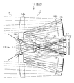
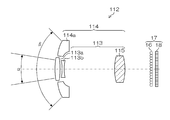
- FIG. 2 is a cross-sectional view illustrating the first embodiment of the imaging unit 11 of the automatic tracking imaging apparatus 10.
- the imaging unit 11 includes a photographing optical system 12 and a directivity sensor 17.
- the photographing optical system 12 is arranged on the same optical axis, and a central optical system 13 as a first optical system and an annular optical system as a concentric second optical system at the periphery thereof. 14.
- the central optical system 13 is a wide-angle optical system (wide-angle lens) that includes a first lens 13 a, a second lens 13 b, a third lens 13 c, a fourth lens 13 d, and a common lens 15. A wide-angle image is formed on the microlens array 16.
- the annular optical system 14 is a telephoto optical system (telephoto lens) including a first lens 14a, a second lens 14b, a first reflection mirror 14c as a reflection optical system, a second reflection mirror 14d, and a common lens 15.
- a telephoto image is formed on the microlens array 16.
- the light beam incident through the first lens 14a and the second lens 14b is reflected twice by the first reflection mirror 14c and the second reflection mirror 14d, and then passes through the common lens 15.
- the light beam is folded back by the first reflecting mirror 14c and the second reflecting mirror 14d, so that the length in the optical axis direction of the telephoto optical system (telephoto lens) having a long focal length is shortened.
- the directivity sensor 17 includes a microlens array 16 and an image sensor 18.
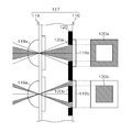
- FIG. 3 is an enlarged view of a main part of the microlens array 16 and the image sensor 18.
- the microlens array 16 includes a plurality of microlenses (pupil imaging lenses) 16 a arranged in a two-dimensional manner, and the horizontal and vertical intervals between the microlenses are the photoelectric conversion elements of the image sensor 18. This corresponds to the interval of three light receiving cells 18a. That is, each microlens of the microlens array 16 is formed corresponding to the position of every two light receiving cells in each of the horizontal direction and the vertical direction.
- Each microlens 16a of the microlens array 16 has a circular central pupil image (first pupil image) 17a and an annular pupil image (first pupil image) corresponding to the central optical system 13 and the annular optical system 14 of the photographing optical system 12. 2b) 17b is formed on the light receiving cell 18a in the corresponding light receiving region of the image sensor 18.
- 3 ⁇ 3 light receiving cells 18 a having a lattice shape (square lattice shape) are allocated per microlens 16 a of the microlens array 16.
- one microlens 16a and a light receiving cell group (3 ⁇ 3 light receiving cells 18a) corresponding to one microlens 16a are referred to as a unit block.
- the central pupil image 17a is formed only on the light receiving cell 18a at the center of the unit block, and the annular pupil image 17b is formed on eight light receiving cells 18a around the unit block.
- a wide-angle image corresponding to the central optical system 13 and a telephoto image corresponding to the annular optical system 14 can be simultaneously captured as described later.
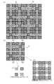
- FIG. 4 is a diagram showing a color filter array and the like disposed in the image sensor 18.
- the microlens array 16 is omitted.
- the region indicated by a circle includes 3 ⁇ 3 light receiving cells on which pupil images are formed by the microlenses 16 a of the microlens array 16.
- the unit block to be included is shown.
- a color filter array composed of color filters arranged on each light receiving cell is provided.
- This color filter array is constituted by three primary color filters (hereinafter referred to as R filter, G filter, and B filter) that transmit light in each wavelength band of red (R), green (G), and blue (B).
- R filter three primary color filters
- G filter three primary color filters
- B filter blue filter
- One of the RGB filters is disposed on each light receiving cell.
- the light receiving cell in which the R filter is disposed is referred to as “R light receiving cell”
- the light receiving cell in which the G filter is disposed is referred to as “G light receiving cell”
- B light receiving cell the light receiving cell in which the B filter is disposed
- the color filter array shown in part (a) of FIG. 4 includes 6 ⁇ 6 light receiving cells as basic blocks B (blocks indicated by a thick frame in part (a) of FIG. 4 and part (b) of FIG. 4). ), And the basic block B is repeatedly arranged in the horizontal direction and the vertical direction.
- the basic block B is composed of four unit blocks B1 to B4.
- the image of the group of the center light receiving cells is a Bayer array mosaic image. Accordingly, a color image can be obtained by demosaicing the mosaic image of the Bayer array.
- a group of eight light receiving cells around each central light receiving cell of the unit blocks B1 to B4 includes all the light receiving cells of RGB in the eight light receiving cells. (R light receiving cell, G light receiving cell, B light receiving cell) and the RGB light receiving cells are arranged in the same pattern regardless of the unit blocks B1 to B4.
- the G light receiving cells are arranged in the four light receiving cells at the four corners of each of the unit blocks B1 to B4, and the R light receiving cells are arranged in the two upper and lower light receiving cells across the center light receiving cell.
- the B light receiving cells are arranged in the two left and right light receiving cells with the central light receiving cell interposed therebetween.
- the R light receiving cell, the G light receiving cell, and the B light receiving cell are respectively arranged at symmetrical positions with respect to the center light receiving cell (center) of the unit block.
- the pixel value of the G pixel at the center position of the unit block (1 microlens) can be obtained.
- Pixel values can be acquired.
- the pixel values of the RGB light receiving cells in the unit block are used. Therefore, it is not necessary to generate pixel values of pixels in a specific wavelength range by interpolating the pixel values of the light receiving cells of the surrounding unit blocks, and the resolution of the output image (substantial number of pixels) ) Is not reduced.
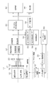
- FIG. 5 is a block diagram showing an embodiment of the internal configuration of the automatic tracking imaging apparatus 10.
- the automatic tracking imaging apparatus 10 includes a photographing optical system 12 having the central optical system 13 and the annular optical system 14 described with reference to FIG. 2, a microlens array 16 and an image sensor described with reference to FIGS. 3 and 4.
- An imaging unit 11 including a directional sensor 17 having 18 is provided.
- the imaging unit 11 preferably includes a focus adjustment unit 19 that performs focus adjustment of the telephoto optical system (annular optical system 14).
- the focus adjustment unit 19 can be configured by, for example, a voice coil motor or the like that moves the entire or part of the annular optical system 14 in the optical axis direction.
- the focus of the telephoto image can be determined based on the contrast of the focus detection area of the telephoto image, but the focus adjustment method is not limited to this.
- a focus adjustment unit may be provided separately or pan focus may be used.
- the pan / tilt device (electric head) 30 has a pan mechanism that rotates the imaging unit 11 in the horizontal direction (pan direction) with respect to the apparatus body 2 and a vertical direction (tilt direction).
- a tilt mechanism (hereinafter referred to as “pan / tilt mechanism”) 32 for rotating, a pan driving unit 34, a tilt driving unit 36, and the like are provided.
- the pan / tilt mechanism 32 includes a home position sensor that detects a reference position of a rotation angle (pan angle) in the pan direction and a home position sensor that detects a reference position of a tilt angle (tilt angle) in the tilt direction.
- the pan driving unit 34 and the tilt driving unit 36 each have a stepping motor and a motor driver, and output a driving force to the pan / tilt mechanism 32 to drive the pan / tilt mechanism 32.
- the imaging unit 11 captures time-series wide-angle images and telephoto images via the photographing optical system 12 and the directivity sensor 17, and each of the directivity sensors 17 (image sensors 18) via the photographing optical system 12.
- the subject image formed on the light receiving surface of the light receiving cell is converted into a signal voltage (or charge) in an amount corresponding to the amount of incident light.
- the signal voltage (or charge) accumulated in the image sensor 18 is accumulated in the light receiving cell itself or an attached capacitor.
- the stored signal voltage (or charge) is read out together with the selection of the light receiving cell position by using a method of a MOS type image pickup device (so-called CMOS sensor) using the XY address method.
- CMOS sensor MOS type image pickup device
- Signal can be read out.
- pixel signals indicating a wide-angle image and a telephoto image are continuously read from the image sensor 18 at a predetermined frame rate (for example, the number of frames per second is 24p, 30p, or 60p).
- the pixel signal (voltage signal) read from the image sensor 18 is converted into an output signal for each light receiving cell for the purpose of reducing correlated double sampling processing (noise (particularly thermal noise) included in the sensor output signal).
- the pixel signal for each light-receiving cell is sampled and held by a process of obtaining accurate pixel data by taking the difference between the included feedthrough component level and the signal component level, and is amplified and applied to the A / D converter 20 .
- the A / D converter 20 converts sequentially input pixel signals into digital signals and outputs them to the image acquisition unit 22. Note that some MOS type sensors include an A / D converter. In this case, a digital signal is directly output from the image sensor 18.
- the image acquisition unit 22 can acquire the pixel signal indicating the wide-angle image and the pixel signal indicating the telephoto image simultaneously or selectively by selecting the light receiving cell position of the image sensor 18 and reading out the pixel signal. .
- a pixel signal indicating an image (a pixel signal indicating a mosaic image of a Bayer array) can be acquired.
- a pixel signal indicating a telephoto image of eight light receiving cells (light receiving cells around a 3 ⁇ 3 light receiving cell) per microlens can be acquired.
- the pixel signals indicating the wide-angle image and the telephoto image acquired by the image acquisition unit 22 are output to the digital signal processing unit 40 and the object detection unit 50, respectively.
- the digital signal processing unit 40 performs offset processing, gamma correction processing, and demosaic processing on RGB mosaic image signals for input digital pixel signals (RGB dot-sequential R signals, G signals, and B signals).
- the predetermined signal processing is performed.
- the demosaic process is a process of calculating all color information for each pixel from the RGB mosaic image corresponding to the color filter array of the single-plate image sensor 18, and is also referred to as a synchronization process.
- this is a process of calculating color information of all RGB for each pixel from a mosaic image composed of RGB.
- the demosaic processing unit included in the digital signal processing unit 40 has no R light receiving cell and B light receiving cell at the position of the G light receiving cell in the wide-angle image (Bayer array mosaic image).
- R signal and B signal of the R light receiving cell and B light receiving cell are respectively interpolated to generate R signal and B signal at the position of the G light receiving cell.
- the G light receiving cell around the R light receiving cell, the G signal of the B light receiving cell, and the B signal are respectively interpolated.
- G signal and B signal are generated at the position of the R light receiving cell, and since there are no G light receiving cell and R light receiving cell at the position of the B light receiving cell of the mosaic image, the G light receiving cells around the B light receiving cell, The G signal and R signal at the position of the B light receiving cell are generated by interpolating the G signal and R signal of the R light receiving cell, respectively.
- the telephoto image is composed of eight mosaic images per microlens 16a (eight around the 3 ⁇ 3 unit block) as shown in part (c2) of FIG. 4, and in the eight light receiving cells. Includes all the RGB color information (R light receiving cell, G light receiving cell, B light receiving cell), the demosaic processing unit uses the output signals of the eight light receiving cells in the unit block.
- the demosaic processing unit that performs demosaic processing of the mosaic image of the telephoto image obtains the average value of the pixel values of the four G light receiving cells in the unit block, thereby obtaining the center position of the unit block (1 microlens).
- the demosaic processing unit that performs demosaic processing of the mosaic image of the telephoto image obtains the average value of the pixel values of the four G light receiving cells in the unit block, thereby obtaining the center position of the unit block (1 microlens).
- the R pixel value and B pixel value of the pixel at the center position of the block are calculated.
- the demosaic image of the telephoto image of the two demosaic images of the wide-angle image and the telephoto image generated by the demosaic processing unit is demosaiced using the output signals of the eight light receiving cells in the unit block.
- the resolution is substantially higher than the demosaic image of the wide-angle image in which the demosaic process is performed using (interpolating) the output signals of the light receiving cells of the surrounding unit blocks.
- the digital signal processing unit 40 performs RGB / YC conversion for generating the luminance signal Y and the color difference signals Cb, Cr from the RGB color information (R signal, G signal, B signal) demosaiced by the demosaic processing unit. And generating image signals for recording and displaying moving images indicating wide-angle images and telephoto images at a predetermined frame rate.
- Image signals indicating a wide-angle image and a telephoto image processed by the digital signal processing unit 40 are output to the recording unit 42 and the display unit 44, respectively.
- the recording unit 42 records an image signal for moving image recording indicating the wide-angle image and the telephoto image processed by the digital signal processing unit 40 on a recording medium (hard disk, memory card, etc.). Note that the recording unit 42 may record only the telephoto image.
- the display unit 44 displays the wide-angle image and the telephoto image by the moving image display image signal indicating the wide-angle image and the telephoto image processed by the digital signal processing unit 40.
- the display unit 44 can also reproduce a wide-angle image and a telephoto image based on the image signal recorded in the recording unit 42.
- the object detection unit 50 detects the tracking target object based on the pixel signal indicating the wide-angle image and the telephoto image acquired by the image acquisition unit 22, and the position information of the detected object in the pan / tilt control unit
- a first object detection unit 52 that detects an object based on a telephoto image and detects position information of the object in the telephoto image; detects an object based on the wide-angle image;
- a second object detection unit 54 that detects position information in the image.
- a method for detecting an object in the first object detection unit 52 and the second object detection unit 54 a method for detecting a specific object by an object recognition technique represented by a technique for performing human face recognition, or a moving object is used.
- the object detection method based on object recognition is a method of registering the appearance characteristics of a specific object in advance as an object dictionary, and comparing the image extracted from the captured image while changing its position and size with the object dictionary. It is a method of recognizing an object.
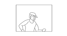
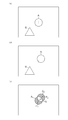
- 6 (a) and 6 (b) are diagrams showing examples of a wide-angle image and a telephoto image, respectively.
- region shown with the broken line in a wide angle image has shown the imaging range of the telephoto image.
- the second object detection unit 54 can detect a face, but the first object detection unit 52 cannot detect a face. This is because the telephoto image contains only a part of the human face and cannot recognize the face.
- the position information in the wide-angle image of the human face (object) detected by the second object detection unit 54 is output to the pan / tilt control unit 60.
- the first object detection unit 52 detects an object based on the telephoto image
- the position information of the object detected by the first object detection unit 52 in the telephoto image is used as the second object detection unit 54. Is output to the pan / tilt control unit 60 in preference to the position information in the wide-angle image of the detected object. This is because the first object detection unit 52 has higher object position detection accuracy than the second object detection unit 54.
- a mode selection unit 56 for selecting the first tracking mode or the second tracking mode is provided.
- the first tracking mode only the position information of the object detected by the second object detection unit 54 in the wide-angle image is output to the pan / tilt control unit 60, and pan / tilt is performed based on the position information in the wide-angle image.
- the device 30 is controlled.
- the second tracking mode when the first object detection unit 52 and the second object detection unit 54 are used together and an object is detected by the first object detection unit 52, the object in the telephoto image of the object is displayed.
- the position information at is preferentially output to the pan / tilt control unit 60 and the pan / tilt device 30 is controlled based on the position information in the telephoto image.
- the position information of the object detected by the second object detection unit 54 in the wide-angle image is output to the pan / tilt control unit 60, and the pan / tilt device 30 is controlled based on the position information in the wide-angle image. is there.
- the pan / tilt control unit 60 controls the pan / tilt device 30 based on the position information of the object in the image (in the wide-angle image or in the telephoto image) input from the object detection unit 50 as described above.
- Pan drive unit 34 tilt drive so that position information in the image of the object (for example, in the case of a tracking target face, the center of gravity of the face region) moves to the center position of the image (position on the optical axis).
- the pan / tilt mechanism 32 (that is, the shooting direction by the imaging unit 11) is controlled via the unit 36.
- FIG. 7 shows a telephoto image showing a state in which tracking control is performed so that a specific object (person's face) comes to the center of the telephoto image.
- the pan / tilt mechanism 32 may be controlled so that it enters at least the angle of view of the telephoto image (preferably within a certain range near the center of the telephoto image (for example, within the focus detection region)).
- the first object detection unit 52 includes two time-series telephoto images (the telephoto image acquired previously (the portion (a) in FIG. 8) and the telephoto image acquired this time (FIG. 8).
- the difference image (part (c) in FIG. 8) obtained by taking the difference (part (b)) is detected.
- the object A of the objects A and B is moving, and the object B is stopped.
- the difference images A 1 and A 2 are images generated by the movement of the object A.
- the barycentric positions of the difference images A 1 and A 2 are calculated and set as positions P 1 and P 2 , respectively, and the midpoint of the line segment connecting these positions P 1 and P 2 is set as a position G. Then, this position G is set as a position in the telephoto image of the moving object (object A).
- the pan / tilt mechanism 32 (that is, the shooting direction by the imaging unit 11) so that the position G of the object A in the telephoto image calculated in this way moves to the center position (position on the optical axis) of the telephoto image. Is repeatedly controlled, the object A moves (converges) to the center position of the telephoto image.
- the second object detection unit 54 can also detect a tracking target object (moving object) based on the wide-angle image and detect the position of the object in the wide-angle image. .
- a tracking target object moving object
- the imaging unit 11 moves (moves by the pan / tilt mechanism 32 or moves by mounting the automatic tracking imaging device 10)
- the background between time-series images also moves. Detects an object moving in the real space regardless of the movement of the imaging unit 11 by shifting the images so that the backgrounds of the time-series images match and taking the difference image between the shifted images. can do.
- the moving object detection method is not limited to the above embodiment.
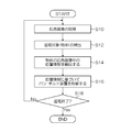
- FIG. 9 is a flowchart showing an example of an automatic tracking control method by the automatic tracking imaging apparatus according to the present invention, and shows a case where the first tracking mode is selected by the mode selection unit 56.
- the second object detection unit 54 acquires a wide-angle image from the image acquisition unit 22 (step S10), and detects a tracking target object from the acquired wide-angle image (step S12).
- the second object detection unit 54 calculates position information of the detected object in the wide-angle image (step S14).
- the pan / tilt control unit 60 inputs position information in the wide-angle image of the object from the second object detection unit 54, and the pan / tilt control unit 60 makes the object come to the center of the wide-angle image based on the input position information.
- the tilt device 30 is controlled (step S16).
- step S18 it is determined whether or not the automatic tracking imaging has been completed. If it is determined that the automatic tracking imaging has not been completed, the process proceeds to step S10. Thereby, the processing from step S10 to step S18 is repeated, and imaging with automatic tracking of the object is performed. On the other hand, when it is determined that the automatic tracking imaging is finished, the automatic tracking imaging is finished. Note that whether or not automatic tracking imaging has ended may be determined by turning the power on or off, or by a switch input indicating whether or not automatic tracking imaging is to be performed.
- FIG. 10 is a flowchart showing another example of the automatic tracking control method by the automatic tracking imaging apparatus according to the present invention, and shows the case where the second tracking mode is selected by the mode selection unit 56.
- the first object detection unit 52 acquires a telephoto image from the image acquisition unit 22 (step S20), and detects a tracking target object from the acquired telephoto image (step S22).
- the first object detection unit 52 determines whether or not an object is detected in step S22 (step S24). When an object is detected (in the case of “Yes”), the first object detection unit 52 calculates position information of the detected object in the telephoto image (step S26).
- step S28 the process proceeds to step S28, and the second object detection unit 54 performs the processing from step S28 to step S32.
- the processing from step S28 to step S32 is the same as the processing from step S10 to step S14 shown in FIG. That is, the second object detection unit 54 acquires a wide-angle image from the image acquisition unit 22 (step S28), detects an object to be tracked from the acquired wide-angle image (step S30), and in the wide-angle image of the detected object. Is calculated (step S32).
- the pan / tilt control unit 60 inputs the position information of the object in the telephoto image detected in step S26 or the position information of the object in the wide-angle image detected in step S32, and enters the input position information. Based on this, the pan / tilt device 30 is controlled so that the object is located at the center position in the telephoto image or at the center position in the wide-angle image (step S34).
- the pan / tilt device 30 is controlled by the pan / tilt control unit 60 when the first object detection unit 52 detects an object from the telephoto image based on the position information of the object in the telephoto image. Needless to say, the control of the tilt device 30 is prioritized.
- step S36 it is determined whether or not automatic tracking imaging has ended. If it is determined that the automatic tracking imaging has not ended, the process proceeds to step S20. Thereby, the processing from step S20 to step S36 is repeated, and imaging with automatic tracking of the object is performed. On the other hand, when it is determined that the automatic tracking imaging is finished, the automatic tracking imaging is finished.
- FIG. 11 is a side view showing another embodiment of the directivity sensor.
- the directivity sensor 117 includes a microlens array 118 serving as a pupil dividing unit, a light shielding member 120 functioning as a light shielding mask, and an image sensor 116 in which a part of the light receiving cells 116 a and 116 b is shielded from light by the light shielding member 120. ing.
- the light receiving cells 116a and the light receiving cells 116b partially shielded by the light shielding member 120 are provided alternately (checker flag shape) in the horizontal direction and the vertical direction of the image sensor 116.
- the microlens array 118 has microlenses 118 a that correspond one-to-one with the light receiving cells 116 a and 116 b of the image sensor 116.
- the light shielding member 120 regulates the opening of the light receiving cells 116a and 116b of the image sensor 116, and has an opening shape corresponding to the central optical system 13 and the annular optical system 14 of the photographing optical system 12 shown in FIG. ing. Note that red (R), green (G), and blue (B) color filters are disposed below each lens of the microlens array 118.
- the periphery of the opening is shielded by the light shielding portion 120a of the light shielding member 120, while in the light receiving cell 116b, the center of the opening is shielded by the light shielding portion 120b of the light shielding member 120.
- the light beam that has passed through the central optical system 13 of the photographic optical system 12 is pupil-divided by the microlens array 118 and the light shielding portion 120a of the light shielding member 120 and enters the light receiving cell 116a.
- the light beam that has passed through the optical system 14 is divided into pupils by the microlens array 118 and the light shielding portion 120b of the light shielding member 120, and enters the light receiving cell 116b.
- the pixel signal of the wide-angle image can be read from each light receiving cell 116a of the image sensor 116, and the pixel signal of the telephoto image can be read from each light receiving cell 116b of the image sensor 116.
- FIG. 12 is a cross-sectional view showing another embodiment of an imaging unit applicable to the automatic tracking imaging device 10.
- This imaging unit is configured by a photographing optical system 112 and a directivity sensor 17. Since the directivity sensor 17 is the same as that shown in FIGS. 2 and 3, the photographing optical system 112 will be described below.
- the photographing optical system 112 is composed of a central optical system 113 at the center and an annular optical system 114 at the periphery thereof arranged on the same optical axis.
- the central optical system 113 is a telephoto optical system including a first lens 113a, a second lens 113b, and a common lens 115, and has an angle of view ⁇ .
- the annular optical system 114 is a wide-angle optical system including a lens 114 a and a common lens 115, has an angle of view ⁇ ( ⁇ > ⁇ ), and is wider than the central optical system 113.
- the photographing optical system 112 does not use a reflecting mirror
- the central optical system 113 is a telephoto optical system
- the annular optical system 114 is a wide-angle optical system. It is different in that.
- the pan / tilt mechanism 32 that rotates the imaging unit 11 in the pan direction and the tilt direction is provided in the apparatus main body 2. It may be mounted on a pan head (pan / tilt device). Note that the automatic tracking imaging apparatus according to the present invention can be used as, for example, a surveillance camera or an in-vehicle camera.
- the object to be tracked may be initially set by the operator using a touch panel or the like from the wide-angle image displayed on the display unit 44.
- the second optical system provided in the peripheral portion of the first optical system is an annular optical system, but is not limited to this, and is arranged on a concentric circle with the optical axis as the center. It may be configured by a plurality of optical systems provided.
- 2 is not limited to a concave mirror or a convex mirror, and may be a plane mirror, and the number of reflection mirrors is not limited to two. You may make it provide more sheets.
- the focus adjustment unit may move the common lens of the central optical system and the annular optical system, or the image sensor in the optical axis direction.
- DESCRIPTION OF SYMBOLS 10 Automatic tracking imaging device, 11 ... Imaging part, 12, 112 ... Shooting optical system, 13, 113 ... Central optical system, 14, 114 ... Annular optical system, 16, 118 ... Micro lens array, 16a, 118a ... Micro lens , 17, 117 ... Directional sensor, 18, 116 ... Image sensor, 18a, 116a, 116b ... Light receiving cell, 22 ... Image acquisition unit, 30 ... Pan / tilt device, 32 ... Pan / tilt mechanism, 42 ... Recording unit, DESCRIPTION OF SYMBOLS 50 ... Object detection part, 52 ... 1st object detection part, 54 ... 2nd object detection part, 56 ... Mode selection part, 60 ... Pan / tilt control part, 120 ... Light shielding member
Landscapes
- Engineering & Computer Science (AREA)
- Multimedia (AREA)
- Signal Processing (AREA)
- Physics & Mathematics (AREA)
- General Physics & Mathematics (AREA)
- Spectroscopy & Molecular Physics (AREA)
- Studio Devices (AREA)
- Optics & Photonics (AREA)
- Accessories Of Cameras (AREA)
Priority Applications (3)
| Application Number | Priority Date | Filing Date | Title |
|---|---|---|---|
| CN201480074827.5A CN105960796B (zh) | 2014-02-18 | 2014-12-15 | 自动跟踪摄像装置 |
| EP14883490.6A EP3110132B1 (en) | 2014-02-18 | 2014-12-15 | Automatic tracking image-capture apparatus |
| US15/206,617 US9924084B2 (en) | 2014-02-18 | 2016-07-11 | Auto-tracking imaging apparatus including wide-angle and telephoto optical systems |
Applications Claiming Priority (2)
| Application Number | Priority Date | Filing Date | Title |
|---|---|---|---|
| JP2014-028339 | 2014-02-18 | ||
| JP2014028339A JP6027560B2 (ja) | 2014-02-18 | 2014-02-18 | 自動追尾撮像装置 |
Related Child Applications (1)
| Application Number | Title | Priority Date | Filing Date |
|---|---|---|---|
| US15/206,617 Continuation US9924084B2 (en) | 2014-02-18 | 2016-07-11 | Auto-tracking imaging apparatus including wide-angle and telephoto optical systems |
Publications (1)
| Publication Number | Publication Date |
|---|---|
| WO2015125388A1 true WO2015125388A1 (ja) | 2015-08-27 |
Family
ID=53877917
Family Applications (1)
| Application Number | Title | Priority Date | Filing Date |
|---|---|---|---|
| PCT/JP2014/083090 WO2015125388A1 (ja) | 2014-02-18 | 2014-12-15 | 自動追尾撮像装置 |
Country Status (5)
| Country | Link |
|---|---|
| US (1) | US9924084B2 (zh) |
| EP (1) | EP3110132B1 (zh) |
| JP (1) | JP6027560B2 (zh) |
| CN (1) | CN105960796B (zh) |
| WO (1) | WO2015125388A1 (zh) |
Cited By (1)
| Publication number | Priority date | Publication date | Assignee | Title |
|---|---|---|---|---|
| JP2018533245A (ja) * | 2015-10-30 | 2018-11-08 | レイセオン カンパニー | デュアル視野光学システム |
Families Citing this family (30)
| Publication number | Priority date | Publication date | Assignee | Title |
|---|---|---|---|---|
| JP6077967B2 (ja) * | 2013-08-27 | 2017-02-08 | 富士フイルム株式会社 | 撮像装置 |
| WO2015098110A1 (ja) * | 2013-12-27 | 2015-07-02 | パナソニックIpマネジメント株式会社 | 撮像装置、撮像システムおよび撮像方法 |
| KR102269601B1 (ko) * | 2014-01-14 | 2021-06-28 | 삼성전자주식회사 | 이중 초점 렌즈 및 이를 포함하는 촬상 장치 |
| TWI518437B (zh) * | 2014-05-12 | 2016-01-21 | 晶睿通訊股份有限公司 | 動態對焦調整系統及其動態對焦調整方法 |
| US9521830B2 (en) * | 2014-08-21 | 2016-12-20 | Identiflight, Llc | Bird or bat detection and identification for wind turbine risk mitigation |
| EP3183687B1 (en) | 2014-08-21 | 2020-07-08 | IdentiFlight International, LLC | Avian detection system and method |
| EP3214832B1 (en) * | 2014-10-31 | 2019-11-27 | Fujifilm Corporation | Imaging device and method for recognizing target object |
| USD811462S1 (en) | 2015-11-16 | 2018-02-27 | Axis Ab | Monitoring camera |
| US10761417B2 (en) * | 2015-11-30 | 2020-09-01 | Lg Electronics Inc. | Smart watch and method for controlling same |
| CN105718887A (zh) * | 2016-01-21 | 2016-06-29 | 惠州Tcl移动通信有限公司 | 基于移动终端摄像头实现动态捕捉人脸摄像的方法及系统 |
| WO2017199559A1 (ja) * | 2016-05-17 | 2017-11-23 | 富士フイルム株式会社 | 撮像装置、撮像方法、プログラム、及び非一時的記録媒体 |
| EP3461127B1 (en) * | 2016-05-17 | 2024-03-06 | FUJIFILM Corporation | Stereo camera and stereo camera control method |
| WO2018045319A1 (en) * | 2016-09-01 | 2018-03-08 | Catalyft Labs, Inc. | Multi-functional weight rack and exercise monitoring system for tracking exercise movements |
| KR20180070264A (ko) * | 2016-12-16 | 2018-06-26 | 삼성전자주식회사 | 패닝 샷 이미지 획득 방법 및 이를 지원하는 전자 장치 |
| CN110574359B (zh) * | 2017-05-16 | 2021-03-02 | 富士胶片株式会社 | 摄像装置及图像合成装置 |
| WO2018235565A1 (ja) * | 2017-06-21 | 2018-12-27 | 富士フイルム株式会社 | 撮像装置及び移動撮像装置 |
| JP2019080226A (ja) * | 2017-10-26 | 2019-05-23 | キヤノン株式会社 | 撮像装置、撮像装置の制御方法、及びプログラム |
| US10593014B2 (en) * | 2018-03-26 | 2020-03-17 | Ricoh Company, Ltd. | Image processing apparatus, image processing system, image capturing system, image processing method |
| JP2019186630A (ja) * | 2018-04-03 | 2019-10-24 | キヤノン株式会社 | 撮像装置及びその制御方法及びプログラム |
| EP3564917B1 (en) * | 2018-05-04 | 2020-07-01 | Axis AB | A method for detecting motion in a video sequence |
| CN108429881A (zh) * | 2018-05-08 | 2018-08-21 | 山东超景深信息科技有限公司 | 免通过反复变焦取景的长焦拍摄云台相机系统应用方法 |
| JP7120835B2 (ja) * | 2018-07-18 | 2022-08-17 | トヨタ自動車株式会社 | 画像処理装置 |
| JP7262997B2 (ja) * | 2018-12-27 | 2023-04-24 | キヤノン株式会社 | 制御装置、撮像装置、および、プログラム |
| AT522115A1 (de) * | 2019-01-24 | 2020-08-15 | Zactrack Gmbh | Bühnentechnische Vorrichtung und Verfahren zur Bestimmung einer Korrelationsfunktion |
| CN110602389B (zh) * | 2019-08-30 | 2021-11-02 | 维沃移动通信有限公司 | 一种显示方法及电子设备 |
| KR20210028808A (ko) | 2019-09-04 | 2021-03-15 | 삼성전자주식회사 | 이미지 센서 및 이를 포함하는 촬상 장치 |
| JP7354773B2 (ja) * | 2019-11-01 | 2023-10-03 | 株式会社Jvcケンウッド | 物体検出装置、物体検出方法、及び物体検出プログラム |
| JP7467114B2 (ja) * | 2019-12-27 | 2024-04-15 | キヤノン株式会社 | 撮像装置およびその制御方法 |
| CN111487647A (zh) * | 2020-03-31 | 2020-08-04 | 中国科学院西安光学精密机械研究所 | 一种基于逆向反射背景的主动照明的高速目标探测装置及方法 |
| US11595575B2 (en) * | 2020-05-11 | 2023-02-28 | Samsung Electronics Co., Ltd. | Image sensor |
Citations (7)
| Publication number | Priority date | Publication date | Assignee | Title |
|---|---|---|---|---|
| WO2003042743A1 (fr) * | 2001-11-13 | 2003-05-22 | Matsushita Electric Industrial Co., Ltd. | Systeme optique d'imagerie a grand angle, dispositif d'imagerie a grand angle, dispositif d'imagerie de surveillance, dispositif d'imagerie a bord d'un vehicule et dispositif de projection equipe du systeme optique d'imagerie a grand angle |
| JP2008129454A (ja) * | 2006-11-22 | 2008-06-05 | Canon Inc | 光学装置、撮像装置、制御方法、及びプログラム |
| JP2010141671A (ja) * | 2008-12-12 | 2010-06-24 | Canon Inc | 撮像装置 |
| JP2011505022A (ja) * | 2007-11-27 | 2011-02-17 | イーストマン コダック カンパニー | 二重の焦点距離のレンズシステム |
| WO2012043211A1 (ja) * | 2010-10-01 | 2012-04-05 | 富士フイルム株式会社 | 撮像装置 |
| JP2012247645A (ja) * | 2011-05-27 | 2012-12-13 | Fujifilm Corp | 撮像装置 |
| JP2012253670A (ja) * | 2011-06-06 | 2012-12-20 | Fujifilm Corp | 撮像装置 |
Family Cites Families (10)
| Publication number | Priority date | Publication date | Assignee | Title |
|---|---|---|---|---|
| JPH1169342A (ja) | 1997-08-22 | 1999-03-09 | Hitachi Denshi Ltd | 侵入物体追尾画像処理システム |
| EP0878965A3 (en) | 1997-05-14 | 2000-01-12 | Hitachi Denshi Kabushiki Kaisha | Method for tracking entering object and apparatus for tracking and monitoring entering object |
| US6734911B1 (en) | 1999-09-30 | 2004-05-11 | Koninklijke Philips Electronics N.V. | Tracking camera using a lens that generates both wide-angle and narrow-angle views |
| JP4140567B2 (ja) | 2004-07-14 | 2008-08-27 | 松下電器産業株式会社 | 物体追跡装置および物体追跡方法 |
| CN1267763C (zh) * | 2004-09-24 | 2006-08-02 | 清华大学 | 一种长焦距大视场无活动部件的微型目标探测系统 |
| JP2006333120A (ja) * | 2005-05-26 | 2006-12-07 | Denso Corp | 撮像モジュール |
| JP2008197540A (ja) * | 2007-02-15 | 2008-08-28 | Funai Electric Co Ltd | 広角撮像装置 |
| JP5201957B2 (ja) * | 2007-11-21 | 2013-06-05 | キヤノン株式会社 | 撮像装置 |
| US9063352B2 (en) * | 2010-10-11 | 2015-06-23 | The Regents Of The University Of California | Telescopic contact lens |
| WO2013027488A1 (ja) * | 2011-08-24 | 2013-02-28 | 富士フイルム株式会社 | 撮像装置 |
-
2014
- 2014-02-18 JP JP2014028339A patent/JP6027560B2/ja active Active
- 2014-12-15 CN CN201480074827.5A patent/CN105960796B/zh active Active
- 2014-12-15 WO PCT/JP2014/083090 patent/WO2015125388A1/ja active Application Filing
- 2014-12-15 EP EP14883490.6A patent/EP3110132B1/en active Active
-
2016
- 2016-07-11 US US15/206,617 patent/US9924084B2/en active Active
Patent Citations (7)
| Publication number | Priority date | Publication date | Assignee | Title |
|---|---|---|---|---|
| WO2003042743A1 (fr) * | 2001-11-13 | 2003-05-22 | Matsushita Electric Industrial Co., Ltd. | Systeme optique d'imagerie a grand angle, dispositif d'imagerie a grand angle, dispositif d'imagerie de surveillance, dispositif d'imagerie a bord d'un vehicule et dispositif de projection equipe du systeme optique d'imagerie a grand angle |
| JP2008129454A (ja) * | 2006-11-22 | 2008-06-05 | Canon Inc | 光学装置、撮像装置、制御方法、及びプログラム |
| JP2011505022A (ja) * | 2007-11-27 | 2011-02-17 | イーストマン コダック カンパニー | 二重の焦点距離のレンズシステム |
| JP2010141671A (ja) * | 2008-12-12 | 2010-06-24 | Canon Inc | 撮像装置 |
| WO2012043211A1 (ja) * | 2010-10-01 | 2012-04-05 | 富士フイルム株式会社 | 撮像装置 |
| JP2012247645A (ja) * | 2011-05-27 | 2012-12-13 | Fujifilm Corp | 撮像装置 |
| JP2012253670A (ja) * | 2011-06-06 | 2012-12-20 | Fujifilm Corp | 撮像装置 |
Non-Patent Citations (1)
| Title |
|---|
| See also references of EP3110132A4 * |
Cited By (1)
| Publication number | Priority date | Publication date | Assignee | Title |
|---|---|---|---|---|
| JP2018533245A (ja) * | 2015-10-30 | 2018-11-08 | レイセオン カンパニー | デュアル視野光学システム |
Also Published As
| Publication number | Publication date |
|---|---|
| JP6027560B2 (ja) | 2016-11-16 |
| CN105960796B (zh) | 2019-08-16 |
| EP3110132A1 (en) | 2016-12-28 |
| JP2015154386A (ja) | 2015-08-24 |
| CN105960796A (zh) | 2016-09-21 |
| EP3110132A4 (en) | 2017-03-01 |
| US20160323504A1 (en) | 2016-11-03 |
| EP3110132B1 (en) | 2021-06-30 |
| US9924084B2 (en) | 2018-03-20 |
Similar Documents
| Publication | Publication Date | Title |
|---|---|---|
| JP6027560B2 (ja) | 自動追尾撮像装置 | |
| JP6641470B2 (ja) | ステレオカメラ及びステレオカメラの制御方法 | |
| JP6302085B2 (ja) | 撮像装置及び対象物認識方法 | |
| JP6214481B2 (ja) | 撮像装置 | |
| JP2016046772A (ja) | 車載カメラ | |
| US10552963B2 (en) | Imaging device, imaging method, and non-transitory recording medium | |
| JP2016048824A (ja) | 追尾装置、追尾システム、及び表示装置 | |
| JP2018134712A (ja) | ロボットシステム及びロボットシステムの制御方法 | |
| JP2016046771A (ja) | 撮像装置、撮像システム及び表示装置 | |
| JP2016046774A (ja) | 撮像装置 | |
| JP2016048825A (ja) | 撮像装置 | |
| JP2016048282A (ja) | 撮像装置 | |
| JP2016046773A (ja) | 撮像装置 | |
| WO2020066341A1 (ja) | 合焦度検出装置、深度マップ生成装置、及び、電子機器 | |
| CN114302046A (zh) | 应用于屏下的摄像装置 | |
| JP2004086401A (ja) | 対象物認識装置および方法 | |
| JP2017038254A (ja) | 撮像装置、画像処理装置、画像処理方法およびプログラム |
Legal Events
| Date | Code | Title | Description |
|---|---|---|---|
| 121 | Ep: the epo has been informed by wipo that ep was designated in this application |
Ref document number: 14883490 Country of ref document: EP Kind code of ref document: A1 |
|
| REEP | Request for entry into the european phase |
Ref document number: 2014883490 Country of ref document: EP |
|
| WWE | Wipo information: entry into national phase |
Ref document number: 2014883490 Country of ref document: EP |
|
| NENP | Non-entry into the national phase |
Ref country code: DE |