EP3110132B1 - Automatic tracking image-capture apparatus - Google Patents
Automatic tracking image-capture apparatus Download PDFInfo
- Publication number
- EP3110132B1 EP3110132B1 EP14883490.6A EP14883490A EP3110132B1 EP 3110132 B1 EP3110132 B1 EP 3110132B1 EP 14883490 A EP14883490 A EP 14883490A EP 3110132 B1 EP3110132 B1 EP 3110132B1
- Authority
- EP
- European Patent Office
- Prior art keywords
- optical system
- image
- wide
- angle
- section
- Prior art date
- Legal status (The legal status is an assumption and is not a legal conclusion. Google has not performed a legal analysis and makes no representation as to the accuracy of the status listed.)
- Active
Links
- 230000003287 optical effect Effects 0.000 claims description 158
- 238000003384 imaging method Methods 0.000 claims description 128
- 238000004091 panning Methods 0.000 claims description 68
- 238000001514 detection method Methods 0.000 claims description 66
- 230000000903 blocking effect Effects 0.000 claims description 18
- 210000001747 pupil Anatomy 0.000 claims description 17
- 238000006243 chemical reaction Methods 0.000 claims description 5
- 238000012545 processing Methods 0.000 description 36
- 238000000034 method Methods 0.000 description 14
- 230000000875 corresponding effect Effects 0.000 description 9
- 238000010586 diagram Methods 0.000 description 8
- 230000002093 peripheral effect Effects 0.000 description 8
- 239000003086 colorant Substances 0.000 description 5
- 210000003128 head Anatomy 0.000 description 4
- 230000001276 controlling effect Effects 0.000 description 3
- 238000005516 engineering process Methods 0.000 description 3
- 230000006870 function Effects 0.000 description 3
- NJPPVKZQTLUDBO-UHFFFAOYSA-N novaluron Chemical compound C1=C(Cl)C(OC(F)(F)C(OC(F)(F)F)F)=CC=C1NC(=O)NC(=O)C1=C(F)C=CC=C1F NJPPVKZQTLUDBO-UHFFFAOYSA-N 0.000 description 3
- 238000012937 correction Methods 0.000 description 2
- 238000013461 design Methods 0.000 description 2
- 230000010354 integration Effects 0.000 description 2
- 238000011160 research Methods 0.000 description 2
- 239000003990 capacitor Substances 0.000 description 1
- 230000002596 correlated effect Effects 0.000 description 1
- 230000006866 deterioration Effects 0.000 description 1
- 230000000694 effects Effects 0.000 description 1
- 238000005070 sampling Methods 0.000 description 1
Images


Classifications
-
- H—ELECTRICITY
- H04—ELECTRIC COMMUNICATION TECHNIQUE
- H04N—PICTORIAL COMMUNICATION, e.g. TELEVISION
- H04N23/00—Cameras or camera modules comprising electronic image sensors; Control thereof
- H04N23/58—Means for changing the camera field of view without moving the camera body, e.g. nutating or panning of optics or image sensors
-
- G—PHYSICS
- G03—PHOTOGRAPHY; CINEMATOGRAPHY; ANALOGOUS TECHNIQUES USING WAVES OTHER THAN OPTICAL WAVES; ELECTROGRAPHY; HOLOGRAPHY
- G03B—APPARATUS OR ARRANGEMENTS FOR TAKING PHOTOGRAPHS OR FOR PROJECTING OR VIEWING THEM; APPARATUS OR ARRANGEMENTS EMPLOYING ANALOGOUS TECHNIQUES USING WAVES OTHER THAN OPTICAL WAVES; ACCESSORIES THEREFOR
- G03B17/00—Details of cameras or camera bodies; Accessories therefor
-
- G—PHYSICS
- G03—PHOTOGRAPHY; CINEMATOGRAPHY; ANALOGOUS TECHNIQUES USING WAVES OTHER THAN OPTICAL WAVES; ELECTROGRAPHY; HOLOGRAPHY
- G03B—APPARATUS OR ARRANGEMENTS FOR TAKING PHOTOGRAPHS OR FOR PROJECTING OR VIEWING THEM; APPARATUS OR ARRANGEMENTS EMPLOYING ANALOGOUS TECHNIQUES USING WAVES OTHER THAN OPTICAL WAVES; ACCESSORIES THEREFOR
- G03B15/00—Special procedures for taking photographs; Apparatus therefor
- G03B15/16—Special procedures for taking photographs; Apparatus therefor for photographing the track of moving objects
-
- H—ELECTRICITY
- H04—ELECTRIC COMMUNICATION TECHNIQUE
- H04N—PICTORIAL COMMUNICATION, e.g. TELEVISION
- H04N23/00—Cameras or camera modules comprising electronic image sensors; Control thereof
- H04N23/50—Constructional details
-
- H—ELECTRICITY
- H04—ELECTRIC COMMUNICATION TECHNIQUE
- H04N—PICTORIAL COMMUNICATION, e.g. TELEVISION
- H04N23/00—Cameras or camera modules comprising electronic image sensors; Control thereof
- H04N23/50—Constructional details
- H04N23/55—Optical parts specially adapted for electronic image sensors; Mounting thereof
-
- H—ELECTRICITY
- H04—ELECTRIC COMMUNICATION TECHNIQUE
- H04N—PICTORIAL COMMUNICATION, e.g. TELEVISION
- H04N23/00—Cameras or camera modules comprising electronic image sensors; Control thereof
- H04N23/60—Control of cameras or camera modules
- H04N23/61—Control of cameras or camera modules based on recognised objects
- H04N23/611—Control of cameras or camera modules based on recognised objects where the recognised objects include parts of the human body
-
- H—ELECTRICITY
- H04—ELECTRIC COMMUNICATION TECHNIQUE
- H04N—PICTORIAL COMMUNICATION, e.g. TELEVISION
- H04N23/00—Cameras or camera modules comprising electronic image sensors; Control thereof
- H04N23/60—Control of cameras or camera modules
- H04N23/67—Focus control based on electronic image sensor signals
-
- H—ELECTRICITY
- H04—ELECTRIC COMMUNICATION TECHNIQUE
- H04N—PICTORIAL COMMUNICATION, e.g. TELEVISION
- H04N23/00—Cameras or camera modules comprising electronic image sensors; Control thereof
- H04N23/60—Control of cameras or camera modules
- H04N23/695—Control of camera direction for changing a field of view, e.g. pan, tilt or based on tracking of objects
-
- H—ELECTRICITY
- H04—ELECTRIC COMMUNICATION TECHNIQUE
- H04N—PICTORIAL COMMUNICATION, e.g. TELEVISION
- H04N23/00—Cameras or camera modules comprising electronic image sensors; Control thereof
- H04N23/60—Control of cameras or camera modules
- H04N23/698—Control of cameras or camera modules for achieving an enlarged field of view, e.g. panoramic image capture
-
- H—ELECTRICITY
- H04—ELECTRIC COMMUNICATION TECHNIQUE
- H04N—PICTORIAL COMMUNICATION, e.g. TELEVISION
- H04N23/00—Cameras or camera modules comprising electronic image sensors; Control thereof
- H04N23/80—Camera processing pipelines; Components thereof
- H04N23/84—Camera processing pipelines; Components thereof for processing colour signals
- H04N23/843—Demosaicing, e.g. interpolating colour pixel values
-
- H—ELECTRICITY
- H04—ELECTRIC COMMUNICATION TECHNIQUE
- H04N—PICTORIAL COMMUNICATION, e.g. TELEVISION
- H04N25/00—Circuitry of solid-state image sensors [SSIS]; Control thereof
- H04N25/10—Circuitry of solid-state image sensors [SSIS]; Control thereof for transforming different wavelengths into image signals
- H04N25/11—Arrangement of colour filter arrays [CFA]; Filter mosaics
- H04N25/13—Arrangement of colour filter arrays [CFA]; Filter mosaics characterised by the spectral characteristics of the filter elements
- H04N25/134—Arrangement of colour filter arrays [CFA]; Filter mosaics characterised by the spectral characteristics of the filter elements based on three different wavelength filter elements
-
- G—PHYSICS
- G03—PHOTOGRAPHY; CINEMATOGRAPHY; ANALOGOUS TECHNIQUES USING WAVES OTHER THAN OPTICAL WAVES; ELECTROGRAPHY; HOLOGRAPHY
- G03B—APPARATUS OR ARRANGEMENTS FOR TAKING PHOTOGRAPHS OR FOR PROJECTING OR VIEWING THEM; APPARATUS OR ARRANGEMENTS EMPLOYING ANALOGOUS TECHNIQUES USING WAVES OTHER THAN OPTICAL WAVES; ACCESSORIES THEREFOR
- G03B17/00—Details of cameras or camera bodies; Accessories therefor
- G03B17/56—Accessories
- G03B17/561—Support related camera accessories
-
- G—PHYSICS
- G03—PHOTOGRAPHY; CINEMATOGRAPHY; ANALOGOUS TECHNIQUES USING WAVES OTHER THAN OPTICAL WAVES; ELECTROGRAPHY; HOLOGRAPHY
- G03B—APPARATUS OR ARRANGEMENTS FOR TAKING PHOTOGRAPHS OR FOR PROJECTING OR VIEWING THEM; APPARATUS OR ARRANGEMENTS EMPLOYING ANALOGOUS TECHNIQUES USING WAVES OTHER THAN OPTICAL WAVES; ACCESSORIES THEREFOR
- G03B41/00—Special techniques not covered by groups G03B31/00 - G03B39/00; Apparatus therefor
-
- G—PHYSICS
- G08—SIGNALLING
- G08B—SIGNALLING OR CALLING SYSTEMS; ORDER TELEGRAPHS; ALARM SYSTEMS
- G08B13/00—Burglar, theft or intruder alarms
- G08B13/18—Actuation by interference with heat, light, or radiation of shorter wavelength; Actuation by intruding sources of heat, light, or radiation of shorter wavelength
- G08B13/189—Actuation by interference with heat, light, or radiation of shorter wavelength; Actuation by intruding sources of heat, light, or radiation of shorter wavelength using passive radiation detection systems
- G08B13/194—Actuation by interference with heat, light, or radiation of shorter wavelength; Actuation by intruding sources of heat, light, or radiation of shorter wavelength using passive radiation detection systems using image scanning and comparing systems
- G08B13/196—Actuation by interference with heat, light, or radiation of shorter wavelength; Actuation by intruding sources of heat, light, or radiation of shorter wavelength using passive radiation detection systems using image scanning and comparing systems using television cameras
- G08B13/19602—Image analysis to detect motion of the intruder, e.g. by frame subtraction
- G08B13/19608—Tracking movement of a target, e.g. by detecting an object predefined as a target, using target direction and or velocity to predict its new position
-
- G—PHYSICS
- G08—SIGNALLING
- G08B—SIGNALLING OR CALLING SYSTEMS; ORDER TELEGRAPHS; ALARM SYSTEMS
- G08B13/00—Burglar, theft or intruder alarms
- G08B13/18—Actuation by interference with heat, light, or radiation of shorter wavelength; Actuation by intruding sources of heat, light, or radiation of shorter wavelength
- G08B13/189—Actuation by interference with heat, light, or radiation of shorter wavelength; Actuation by intruding sources of heat, light, or radiation of shorter wavelength using passive radiation detection systems
- G08B13/194—Actuation by interference with heat, light, or radiation of shorter wavelength; Actuation by intruding sources of heat, light, or radiation of shorter wavelength using passive radiation detection systems using image scanning and comparing systems
- G08B13/196—Actuation by interference with heat, light, or radiation of shorter wavelength; Actuation by intruding sources of heat, light, or radiation of shorter wavelength using passive radiation detection systems using image scanning and comparing systems using television cameras
- G08B13/19617—Surveillance camera constructional details
- G08B13/1963—Arrangements allowing camera rotation to change view, e.g. pivoting camera, pan-tilt and zoom [PTZ]
-
- H—ELECTRICITY
- H04—ELECTRIC COMMUNICATION TECHNIQUE
- H04N—PICTORIAL COMMUNICATION, e.g. TELEVISION
- H04N23/00—Cameras or camera modules comprising electronic image sensors; Control thereof
- H04N23/10—Cameras or camera modules comprising electronic image sensors; Control thereof for generating image signals from different wavelengths
-
- H—ELECTRICITY
- H04—ELECTRIC COMMUNICATION TECHNIQUE
- H04N—PICTORIAL COMMUNICATION, e.g. TELEVISION
- H04N23/00—Cameras or camera modules comprising electronic image sensors; Control thereof
- H04N23/60—Control of cameras or camera modules
- H04N23/667—Camera operation mode switching, e.g. between still and video, sport and normal or high- and low-resolution modes
-
- H—ELECTRICITY
- H04—ELECTRIC COMMUNICATION TECHNIQUE
- H04N—PICTORIAL COMMUNICATION, e.g. TELEVISION
- H04N23/00—Cameras or camera modules comprising electronic image sensors; Control thereof
- H04N23/60—Control of cameras or camera modules
- H04N23/67—Focus control based on electronic image sensor signals
- H04N23/673—Focus control based on electronic image sensor signals based on contrast or high frequency components of image signals, e.g. hill climbing method
-
- H—ELECTRICITY
- H04—ELECTRIC COMMUNICATION TECHNIQUE
- H04N—PICTORIAL COMMUNICATION, e.g. TELEVISION
- H04N23/00—Cameras or camera modules comprising electronic image sensors; Control thereof
- H04N23/60—Control of cameras or camera modules
- H04N23/69—Control of means for changing angle of the field of view, e.g. optical zoom objectives or electronic zooming
Definitions
- the present invention relates to an auto-tracking imaging apparatus, and particularly relates to an auto-tracking imaging apparatus capable of simultaneously capturing a wide-angle image and a telephoto image.
- US 6,734,911 B1 teaches a tracking system that provides high resolution images and a low tracking dropout rate.
- WO 2013/027488 A1 is a PCT application. It discloses an bifocal optical system with a telephoto lens in a central position and a wide-angle lens at the periphery. It also discloses a microlens array in front of a light shielding member that divides the rays from the bifocal optical system into a wide-angle image and a telephoto image on the pixels of a sensor.
- JP1999-69342A JP-H11-69342A
- JP2006-33224A describe a conventional auto-tracking imaging apparatus capable of simultaneously capturing a wide-angle image and a telephoto image.
- Both the systems described in JP1999-69342A ( JP-H11-69342A ) and JP2006-33224A comprise: a wide-angle camera that captures a wide-angle image; and a telephoto camera that is mounted on an electric pan head (panning/tilting device) and captures a telephoto image.
- the wide-angle camera detects a tracking target object from the captured wide-angle image, and the telephoto camera automatically tracks the object by controlling rotation of the electric pan head on the basis of information about a position of the detected object in the wide-angle image, thereby performing telephoto imaging.
- the camera comprises an optical system in which an axis of a narrow-angle lens portion of a central circular part coincides with an axis of a wide-angle lens portion of an annular part surrounding the central circular part, and an image sensor having a central zone, in which a narrow-angle image is formed by the narrow-angle lens portion, and a circumferential zone in which a wide-angle image is formed by the wide-angle lens portion ( JP2003-510666A ).
- the OBT can be captured by using the wide-angle image.
- tracking dropout does not occur.
- the wide-angle image is formed in an annular shape, and the center part of the wide-angle image is vacant. Accordingly, imaging cannot be performed.
- the central circular part is formed as a telephoto lens and the annular part is formed as a wide-angle lens, it is difficult to design an optical system that smoothly connects the narrow-angle and wide-angle images which are captured through these lenses. In this situation, at the boundary between the telephoto image and the wide-angle image, a region, in which an image is not captured, appears.
- the contact lens described in "Photonic Systems Integration Laboratory", the Internet ⁇ URL: http:// psilab.ucsd.edu/research/Telescopic Contact Lens/main.html> is able to solve the problem of parallax between the wide-angle image and the telephoto image.
- a switching shutter is necessary in order to separately obtain two images which are wide-angle and telephoto images. For this reason, a complex system is formed. Further, it is not possible to obtain both images at the same time, and thus information of the wide-angle image is not acquired while the telephoto image is being acquired. Accordingly, there is a problem in that precision of tracking is lowered.
- the present invention has been made in consideration of the above-mentioned situation, and its object is to provide a small-size and inexpensive auto-tracking imaging apparatus capable of simultaneously acquiring wide-angle and telephoto images, of which the optical axes coincide with each other, through a single imaging section, and reliably capturing the tracking target object by using the telephoto image.
- an auto-tracking imaging apparatus comprising: an imaging optical system that is formed of a first optical system at a central portion thereof and a second optical system which is provided at the periphery of the first optical system and has an optical axis the same as that of the first optical system, where one of the optical systems is a wide-angle optical system, and the other is a telephoto optical system; a directional sensor that has a plurality of pixels constituted of photoelectric conversion elements two-dimensionally arranged and that respectively pupil-divides rays incident through the wide-angle and telephoto optical systems so as to selectively receive the rays; a panning/tilting mechanism that rotates an imaging section, which includes the imaging optical system and the directional sensor, in horizontal and vertical directions; an image acquisition section that respectively acquires a wide-angle image, for which light is received from the directional sensor through the wide-angle optical system, and a telephoto image for which light is
- the imaging section single imaging section
- the panning/tilting mechanism is controlled on the basis of the information about the position of the detected object in the image, whereby the object is set to be within the telephoto image (to be automatically tracked).
- the object is set to be within the telephoto image (to be automatically tracked).
- the auto-tracking imaging apparatus further comprises a recording section that records at least the telephoto image in the wide-angle and telephoto images acquired by the image acquisition section. Thereby, a desired object can be checked on the basis of the telephoto image which is recorded by the recording section.
- the object detection section detects a moving object on the basis of at least the wide-angle image in the wide-angle and telephoto images continuously acquired by the image acquisition section, and sets the detected moving object as the tracking target object. Since the tracking target object is moving, it is possible to detect a desired object through detection of the moving object.
- the object detection section recognizes a specific object on the basis of at least the wide-angle image in the wide-angle and telephoto images acquired by the image acquisition section, and sets the recognized specific object as the tracking target object.
- the specific object is a person
- the object detection section recognizes a specific object on the basis of at least the wide-angle image in the wide-angle and telephoto images acquired by the image acquisition section, and sets the recognized specific object as the tracking target object.
- the panning/tilting control section controls the panning/tilting mechanism on the basis of the information about the position of the object, which is detected by the object detection section, in the image, and an angle of view of at least the telephoto image is set to include the detected object.
- the panning/tilting mechanism may be controlled such that the detected object is at the center of the telephoto image, and the panning/tilting mechanism may be controlled such that the detected object is within a predetermined range in the vicinity of the center of the telephoto image.
- the object detection section has a first object detection section that detects the object on the basis of the telephoto image acquired by the image acquisition section, and a second object detection section that detects the object on the basis of the wide-angle image acquired by the image acquisition section.
- the panning/tilting control section controls the panning/tilting mechanism on the basis of the information about a position of the object, which is detected by the first object detection section, in the telephoto image, and controls the panning/tilting mechanism on the basis of the information about a position of the object, which is detected by the second object detection section, in the wide-angle image when the first object detection section is unable to detect the object.
- the panning/tilting mechanism in a case where the object can be detected on the basis of the telephoto image, the panning/tilting mechanism is controlled on the basis of the information about the position of the detected object in the telephoto image.
- the panning/tilting mechanism is controlled on the basis of the wide-angle image, that is, on the basis of the information about the position of the detected object in the wide-angle image.
- the auto-tracking imaging apparatus further comprises a mode selection section that selects a first tracking mode or a second tracking mode.
- the panning/tilting control section controls the panning/tilting mechanism on the basis of only the information about the position of the object detected by the second object detection section in the wide-angle image if the mode selection section selects the first tracking mode, controls the panning/tilting mechanism on the basis of the information about the position of the object detected by the first object detection section in the telephoto image if the mode selection section selects the second tracking mode, and controls the panning/tilting mechanism on the basis of the information about the position of the object detected by the second object detection section in the wide-angle image when the first object detection section is unable to detect the object.
- the first optical system of the imaging optical system is a central optical system that has a circular shape
- the second optical system is an annular optical system that is disposed concentrically around the central optical system. No parallax occurs between the two images captured by the central optical system, which have a circular shape, and the annular optical system which is disposed concentrically around the central optical system.
- each of the optical systems is rotationally symmetric, and thus preferred as an imaging optical system.
- the annular optical system has a reflective optical system that reflects rays twice or more. Thereby, it is possible to shorten the dimension of the annular optical system in the optical axis direction. As a result, it is possible to reduce the size of the imaging section.
- the first optical system is the wide-angle optical system
- the second optical system is the telephoto optical system
- the auto-tracking imaging apparatus further includes a focus adjustment section that performs focus adjustment of the telephoto optical system. Since the telephoto optical system has a depth of field lower than that of the wide-angle optical system and blurring tends to occur in the telephoto optical system, it is preferable that the focus adjustment is performed thereon. It should be noted that the focus adjustment section may be provided also in the wide-angle optical system, and the wide-angle optical system may perform panning and focusing without the focus adjustment section in the wide-angle optical system.
- the directional sensor may have a micro lens array or a light blocking mask that functions as pupil division means.
- the present invention it is possible to simultaneously acquire wide-angle and telephoto images, of which the optical axes coincide with each other, through a single imaging section, and thus it is possible to reduce the size and the cost of the auto-tracking imaging apparatus. Further, the optical axis directions of the wide-angle and telephoto images coincide with each other.
- the tracking target object is detected on the basis of at least the wide-angle image, and the panning/tilting mechanism is controlled on the basis of the information about the position of the detected object in the image, whereby the object can be set to be within the telephoto image (to be automatically tracked). Further, even if the object moves at a high speed, it is possible to capture the object by using the wide-angle image. As a result, there is an effect that no tracking dropout occurs.
- Fig. 1 is a perspective view of an appearance of an auto-tracking imaging apparatus according to the present invention.
- an auto-tracking imaging apparatus 10 mainly has an apparatus main body 2, an imaging section 11, a panning/tilting device 30 ( Fig. 5 ), and a dome cover 6 that covers the imaging section 11.
- the panning/tilting device 30 has a pedestal 4 and a holding section 8 that is fixed onto the pedestal 4 and rotatably holds the imaging section 11.
- the pedestal 4 is disposed to be rotatable about the axis of the vertical direction Z of the apparatus main body 2.
- a pan driving section 34 ( Fig. 5 ) rotates about the axis of the vertical direction Z.
- the holding section 8 has a gear 8A that is provided on the axis the same as the axis of the horizontal direction X, and transfers the driving force from the tilt driving section 36 ( Fig. 5 ) through the gear 8A, thereby rotating (tilting) the imaging section 11 in the up-down direction.
- the dome cover 6 is a vibration-proof and drip-proof cover. It is preferable that the dome cover 6 has a spherical shell shape with a certain thickness at which an intersection point between the axis of the horizontal direction X and the axis of the vertical direction Z is set as a center of a curvature thereof without change in optical performance of the imaging section 11, regardless of an optical axis direction L of the imaging section 11.
- a tripod attaching section (such as a tripod screw hole) not shown in the drawing is provided on the rear surface of the apparatus main body 2.
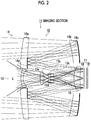
- Fig. 2 is a sectional view illustrating a first embodiment of the imaging section 11 of the auto-tracking imaging apparatus 10.
- the imaging section 11 includes the imaging optical system 12 and the directional sensor 17.
- the imaging optical system 12 includes a central optical system 13 as a first optical system at the center portion and an annular optical system 14 as a second optical system having a concentric shape at the periphery. Each optical system is disposed on the same optical axis.
- the central optical system 13 is a wide-angle optical system (wide-angle lens) including a first lens 13a, a second lens 13b, a third lens 13c, a fourth lens 13d, and a common lens 15, and forms a wide-angle image on a micro lens array 16 constituting the directional sensor 17.
- wide-angle lens wide-angle lens
- the annular optical system 14 is a telephoto optical system (telephoto lens) including a first lens 14a, a second lens 14b, a first reflection mirror 14c as a reflective optical system, a second reflection mirror 14d, and a common lens 15, and forms a telephoto image on a micro lens array 16. Rays, which are incident through the first lens 14a and the second lens 14b, are reflected twice by the first reflection mirror 14c and the second reflection mirror 14d, and thereafter pass through the common lens 15. The rays are bent by the first reflection mirror 14c and the second reflection mirror 14d, whereby a length of the telephoto optical system (telephoto lens) having a long focal length in the optical axis direction is shortened.
- telephoto optical system telephoto lens
- the directional sensor 17 includes a micro lens array 16 and an image sensor 18.
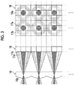
- Fig. 3 is an enlarged view of principal sections of the micro lens array 16 and the image sensor 18.
- the micro lens array 16 is configured such that multiple micro lenses (pupil imaging lenses) 16a are two-dimensionally arranged. Distances between the micro lenses in the horizontal and vertical directions correspond to distances between three light receiving cells 18a as photoelectric conversion elements of the image sensor 18. That is, each micro lens of the micro lens array 16 is formed to correspond to positions of two light receiving cells in each direction of the horizontal and vertical directions.
- each micro lens 16a of the micro lens array 16 forms a central pupil image (first pupil image) 17a having a circular shape and annular pupil image (second pupil image) 17b, which correspond to the central optical system 13 and the annular optical system 14 of the imaging optical system 12, on the light receiving cells 18a in a corresponding light receiving region of the image sensor 18.
- 3 ⁇ 3 light receiving cells 18a having a lattice (square lattice) shape are allocated for each one micro lens 16a of the micro lens array 16.
- a light receiving cell group (3 ⁇ 3 light receiving cells 18a) corresponding to one micro lens 16a and one micro lens 16a is referred to as a unit block.
- the central pupil image 17a is formed only on the light receiving cell 18a at the center of the unit block, and the annular pupil image 17b is formed on the eight light receiving cells 18a at the periphery of the unit block.
- a wide-angle image corresponding to the central optical system 13 and a telephoto image corresponding to the annular optical system 14 are captured at the same time.
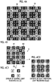
- Figs. 4A to 4C2 are diagrams illustrating a color filter array that is disposed on the image sensor 18.
- the micro lens array 16 is omitted, but the regions indicated by circles represents unit blocks each including 3 ⁇ 3 light receiving cells on which pupil images are formed by the respective micro lenses 16a of the micro lens array 16.
- the color filter array formed of color filters disposed on the respective light receiving cells is provided on an imaging surface of the image sensor 18.
- the color filter array is formed of color filters (hereinafter referred to as R, G, and B filters) which have three primary colors and through which rays with respective wavelength regions of red (R), green (G), and blue (B) are transmitted. Then, any one of the RGB filters is disposed on each light receiving cell.
- R, G, and B filters color filters
- any one of the RGB filters is disposed on each light receiving cell.
- the light receiving cell, on which the R filter is disposed is referred to as an "R light receiving cell”
- the light receiving cell, on which the G filter is disposed is referred to as an "G light receiving cell”
- the light receiving cell, on which the B filter is disposed is referred to as an "B light receiving cell”.
- the color filter array shown in Fig. 4A is configured as follows: 6 ⁇ 6 light receiving cells are set as a basic block B (a block indicated by a large frame of Fig. 4A , and shown in Fig. 4B ), and the basic blocks B are repeatedly arranged in the horizontal and vertical directions.
- the basic block B is formed of four unit blocks B1 to B4.
- Fig. 4C1 shows a group of central light receiving cells (light receiving cells on which rays passing through the central optical system 13 shown in Fig. 3 are incident) of the four unit blocks B1 to B4.
- Fig. 4C2 shows groups of eight peripheral light receiving cells (light receiving cells on which rays passing through the annular optical system 14 shown in Fig. 3 are incident).
- the image of the group of the central light receiving cells is formed of mosaic images having a Bayer array.
- the demosaic processing on the mosaic images having the Bayer array, it is possible to obtain a color image.
- the groups of the central light receiving cells and the eight peripheral light receiving cells of the unit blocks B1 to B4 include all the RGB light receiving cells (R, G, and B light receiving cells) in the eight light receiving cells, and the RGB light receiving cells are arranged with the same pattern regardless of the unit blocks B1 to B4.
- G light receiving cells are disposed on the four light receiving cells at four corners of each of the unit blocks B1 to B4, R light receiving cells are disposed on the two upper and lower light receiving cells with the central light receiving cell interposed therebetween, and B light receiving cells are disposed on the two left and right light receiving cells with the central light receiving cell interposed therebetween.
- the R light receiving cells, the G light receiving cells, and the B light receiving cells are respectively positioned to be symmetric to each other with respect to the central light receiving cell (center) of each unit block.
- the telephoto image which is generated by a group of the peripheral eight light receiving cells of each unit block and corresponds to the annular optical system 14 (telephoto optical system), can be subjected to demosaic processing on the basis of pixel values of the RGB light receiving cells within the unit block.
- the telephoto image which is generated by a group of the peripheral eight light receiving cells of each unit block and corresponds to the annular optical system 14 (telephoto optical system)
- demosaic processing on the basis of pixel values of the RGB light receiving cells within the unit block.
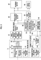
- Fig. 5 is a block diagram illustrating an embodiment of an internal configuration of the auto-tracking imaging apparatus 10.
- the auto-tracking imaging apparatus 10 comprises the imaging section 11 that is formed of the imaging optical system 12, which has the central optical system 13 and the annular optical system 14 described in Fig. 2 and the directional sensor 17 which has the micro lens array 16 and the image sensor 18 described in Figs. 3 and 4A to 4C2 .
- the imaging section 11 comprises a focus adjustment section 19 that performs focus adjustment of the telephoto optical system (annular optical system 14).
- the focus adjustment section 19 can be constituted of, for example, a voice coil motor that moves an entire or partial optical system of the annular optical system 14 in the optical axis direction, and the like. Further, determination as to whether or not the telephoto image is in an in-focus state can be performed on the basis of a contrast of a focus detection region of the telephoto image.
- the focus adjustment method is not limited to this.
- the focus adjustment section may be separately provided, and the panning and focusing function may be used.
- the panning/tilting device (electric pan head) 30 comprises, as shown in Fig. 1 , a panning mechanism that rotates the imaging section 11 in the horizontal direction (panning direction) of the apparatus main body 2, and a panning/tilting mechanism (hereinafter referred to as a "panning/tilting mechanism") 32 that rotates the imaging section 11 in the vertical direction (tilting direction), a pan driving section 34, a tilt driving section 36, and the like.
- the panning/tilting mechanism 32 has a home position sensor that detects a reference position of a rotation angle (pan angle) in the panning direction and a home position sensor that detects a reference position of an inclination angle (tilt angle) in the tilting direction.
- Each of the pan driving section 34 and the tilt driving section 36 has a stepping motor and a motor driver, outputs a driving force to a panning/tilting mechanism 32, and drives the panning/tilting mechanism 32.
- the imaging section 11 captures time-series wide-angle and telephoto images through the imaging optical system 12 and the directional sensor 17, and converts subject images into signal voltages (or electric charges) of which amounts correspond to an amount of incident light.
- the subject images are formed on light receiving surfaces of the light receiving cells (photoelectric conversion elements) of the directional sensor 17 (image sensor 18) through the imaging optical system 12.
- the signal voltages (or electric charges) accumulated in the image sensor 18 can be stored in the light receiving cells themselves or provided capacitors.
- the stored signal voltages (or electric charges) are read in conjunction with selection of positions of the light receiving cells by a method of using MOS-type imaging elements (so-called CMOS sensors) based on an X-Y address system.
- pixel signals which indicate wide-angle images of groups of the central light receiving cells corresponding to the central optical system 13
- pixel signals which indicate telephoto images of groups of the eight peripheral light receiving cells corresponding to the annular optical system 14
- pixel signals which indicate the wide-angle and telephoto images, are continuously read from the image sensor 18, at a predetermined frame rate (for example, a frame number per sec. of 24p, 30p, or 60p).
- the pixel signal (voltage signals), which is read from the image sensor 18, for each light receiving cell is sampled through correlated double sampling processing (processing of acquiring precise pixel data by taking a difference between a feed-through component level and a signal component level included in the output signal of each light receiving cell in order to reduce noise (particularly thermal noise) included in the sensor output signal). Then, the signal is amplified, and thereafter added to an A/D converter 20.
- the A/D converter 20 converts the pixel signals, which are sequentially input, into digital signals, and outputs the signals to the image acquisition section 22.
- the A/D converter may be built into the MOS-type sensor. In this case, the digital signals are output directly from the image sensor 18.
- the image acquisition section 22 selects the positions of the light receiving cells of the image sensor 18 and reads the pixel signals, thereby simultaneously or selectively acquiring the pixel signals, which indicate the wide-angle image, and the pixel signals which indicate the telephoto image.
- the pixel signals of the light receiving cells of the image sensor 18 onto which the central pupil images 17a are incident it is possible to acquire the pixel signals (pixel signals indicating mosaic images having a Bayer array) indicating a wide-angle image of the light receiving cells (each of which is the central light receiving cell of the 3 ⁇ 3 light receiving cells) each of which corresponds to each one micro lens.
- the pixel signals of the light receiving cells of the image sensor 18 onto which the annular pupil images 17b are incident it is possible to acquire the pixel signals (pixel signals indicating mosaic images having a Bayer array) indicating a telephoto image of the light receiving cells (which are the peripheral light receiving cells of the 3 ⁇ 3 light receiving cells) of which every eight light receiving cells correspond to each one micro lens.
- all the pixel signals may be read from the image sensor 18 and temporarily stored in the buffer memory, and groups of the pixel signals of the two images of the wide-angle and telephoto images may be divided from the pixel signals stored in the buffer memory.
- the pixel signals which indicate the wide-angle and telephoto images acquired by the image acquisition section 22, are respectively output to a digital signal processing section 40 and an object detection section 50.
- the digital signal processing section 40 performs predetermined signal processing, such as offset processing, gamma correction processing, and demosaic processing for the signals of the RGB mosaic images, on the input digital pixel signals (sequential R, G, and B signals of RGB points).
- the demosaic processing is processing of calculating information of all colors for each pixel from the RGB mosaic images corresponding to a color filter array of a single-plate-type image sensor 18, and is also referred to as synchronization processing.
- the demosaic processing is processing of calculating information of all colors of RGB for each pixel from the mosaic images having RGB colors.
- the demosaic processing section included in the digital signal processing section 40 does not have the R and B light receiving cells at the positions of the G light receiving cells of the wide-angle image (mosaic images having a Bayer array).
- the R and B signals of the R and B light receiving cells around the G light receiving cells are separately interpolated, and the R and B signals at the positions of the G light receiving cells are generated.
- the G and B signals of the G and B light receiving cells around the R light receiving cells are separately interpolated, and the G and B signals at the positions of the R light receiving cells are generated.
- the G and R signals of the G and R light receiving cells around the B light receiving cells are separately interpolated, and the G and R signals at the positions of the B light receiving cells are generated.
- the telephoto image is formed of the mosaic images of which every eight (eight peripheral blocks of 3x3 unit blocks) images correspond to one micro lens 16a, and the eight light receiving cells include all RGB color information pieces (of the R, G, and B light receiving cells).
- the demosaic processing section is able to generate a single pixel (RGB pixel value) constituting the image, on which the demosaic processing is performed, for each unit block, by using the output signals of the eight light receiving cells in the unit block.
- the demosaic processing section which performs the demosaic processing on the mosaic images of the telephoto image, calculates an average value of the pixel values of the four G light receiving cells in the unit block, thereby calculating a G pixel value of the pixel at the center position of the unit block (single micro lens).
- the demosaic processing section calculates an average value of the pixel values of the two R light receiving cells and an average value of the pixel values of the two B light receiving cells in the unit block, thereby calculating R and B pixel values of the pixels at the center positions of the respective unit blocks.
- the demosaic image of the telephoto image of two demosaic images of the wide-angle and telephoto images generated by the demosaic processing section is subjected to demosaic processing by using the output signals of the eight light receiving cells in the unit block. Accordingly, the resolution of the demosaic image is substantially higher than that of the demosaic image of the wide-angle image which is subjected to demosaic processing by using (interpolating) the output signals of the light receiving cells of the peripheral unit blocks.
- the digital signal processing section 40 performs RGB/YC conversion or the like which generates a luminance signal Y and color difference signals Cb and Cr from the RGB color information pieces (R, G, and B signals) on which demosaic processing is performed by the demosaic processing section, thereby generating image signals for recording and displaying a moving image indicating the wide-angle and telephoto images with the predetermined frame rate.
- the image signals which indicate the wide-angle and telephoto images processed by the digital signal processing section 40, are respectively output to the recording section 42 and the display section 44.
- the recording section 42 records the image signals for recording a moving image indicating the wide-angle and telephoto images processed by the digital signal processing section 40 in a recording medium (such as a hard disk or a memory card).
- the recording section 42 may record only the telephoto image.
- the display section 44 displays the wide-angle and telephoto images on the basis of the image signals for displaying the moving image indicating the wide-angle and telephoto images processed by the digital signal processing section 40.
- the display section 44 may reproduce the wide-angle and telephoto images on the basis of the image signals recorded in the recording section 42.
- the object detection section 50 has: a first object detection section 52 that detects a tracking target object on the basis of the pixel signals indicating the wide-angle and telephoto images acquired by the image acquisition section 22, outputs the information about the position of the detected object in the image to the panning/tilting control section 60, detects the object on the basis of the telephoto image, and detects the information about the position of the object in the telephoto image; and a second object detection section 54 that detects the object on the basis of the wide-angle image, and detects the information about the position of the object in the wide-angle image.
- the object detection method in the first object detection section 52 and second object detection section 54 there is a method of detecting a specific object on the basis of an object recognition technology as a representative of a technology for recognizing a person's face, or a moving object detection method of detecting a moving object as a tracking target object.
- the object detection method based on object recognition is a method in which features of a specific object in a viewing direction are registered as an object dictionary in advance and an object is recognized by comparing the object dictionary with a clipped image while changing a position or a size of the object from the captured image.
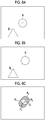
- Figs. 6A and 6B are diagrams respectively illustrating examples of captured wide-angle and telephoto images.
- the region indicated by the dashed line within the wide-angle image represents an imaging range of the telephoto image.
- the wide-angle and telephoto images shown in Figs. 6A and 6B are captured, a person's face is set as a tracking target, and the person's face is detected by using an object (face) recognition technology.
- the second object detection section 54 is able to detect the face, but the first object detection section 52 is unable to detect the face.
- the reason for this is that telephoto image includes only a part of the person's face, and thus face cannot be recognized.
- the second object detection section 54 outputs information about a position of the detected person's face (object) in the wide-angle image to the panning/tilting control section 60.
- the first object detection section 52 detects the object on the basis of the telephoto image
- the first object detection section 52 outputs information about a position of the detected object in the telephoto image to the panning/tilting control section 60 in priority to the information about the position of the object, which is detected by the second object detection section 54, in the wide-angle image.
- the reason for this is that the first object detection section 52 has a higher accuracy in detecting the position of the object than the second object detection section 54.
- a mode selection section 56 which selects a first tracking mode or a second tracking mode.
- the first tracking mode is a mode for outputting only the information about the position of the object detected by the second object detection section 54 in the wide-angle image to the panning/tilting control section 60 and controlling the panning/tilting device 30 on the basis of the information about the position in the wide-angle image.
- the second tracking mode is a mode that uses the first object detection section 52 and the second object detection section 54 in combination.
- the information about the position of the object in the telephoto image is preferentially output to the panning/tilting control section 60, and the panning/tilting device 30 is controlled on the basis of the information about the position in the telephoto image.
- the information about the position of the object detected by the second object detection section 54 in the wide-angle image is output to the panning/tilting control section 60, and the panning/tilting device 30 is controlled on the basis of the information about the position of the object in the wide-angle image.
- the panning/tilting control section 60 is a section that controls the panning/tilting device 30 on the basis of the information about the position of the object in the image (in the wide-angle image or the telephoto image) which is input from the object detection section 50 as described above.
- the panning/tilting control section 60 controls the panning/tilting mechanism 32 (that is, a direction of imaging performed by the imaging section 11) through the pan driving section 34 and the tilt driving section 36 such that the information about the position (for example, a barycentric position of a face region in a case where the tracking target is a face) of the object in the image is moved to the center position (a position on the optical axis) in the image.
- Fig. 7 shows a telephoto image that indicates a state where tracking is controlled such that a specific object (a face of a person) is at the center of the telephoto image.
- tracking target object for example, person's face
- Fig. 7 shows a telephoto image that indicates a state where tracking is controlled such that a specific object (a face of a person) is at the center of the telephoto image.
- the present invention is not limited to this.
- the panning/tilting mechanism 32 may be controlled such that the position (barycentric position) of the object in the image is set in at least an angle of view of the telephoto image (preferably, set in a predetermined range (for example, in a focus detection region) in the vicinity of the center of the telephoto image).
- the first object detection section 52 detects a difference image ( Fig. 8C ) which is obtained from a difference between two time-series telephoto images (a previously acquired telephoto image ( Fig. 8A ) and a currently acquired telephoto image ( Fig. 8B ).
- the difference images A 1 and A 2 are images generated through movement of the object A.
- the barycentric positions of the difference images A 1 and A 2 are calculated, and respectively referred to as positions Pi and P 2 , and the midpoint of a line segment connecting these positions P 1 and P 2 is referred to as a position G.
- the position G is set as a position of the moving object (object A) in the telephoto image.
- the panning/tilting mechanism 32 (that is, the direction of imaging performed by the imaging section 11) is repeatedly controlled such that the position G of the object A in the telephoto image calculated in such a manner is moved to the center position (the position on the optical axis) in the telephoto image. Thereby, the object A is moved (converged) to the center position in the telephoto image.
- the second object detection section 54 is also able to detect the position of the object in the wide-angle image by detecting the tracking target object (moving object) on the basis of the wide-angle image.
- the imaging section 11 is moved (moved by the panning/tilting mechanism 32, or moved since the auto-tracking imaging apparatus 10 is mounted on a vehicle)
- background also moves between time-series images.
- the moving object detection method is not limited to the embodiments.
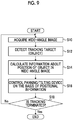
- Fig. 9 is a flowchart illustrating an example of the auto-tracking control method in the auto-tracking imaging apparatus according to the present invention, and shows a case where the mode selection section 56 selects the first tracking mode.
- the second object detection section 54 acquires the wide-angle image from the image acquisition section 22 (step S10), and detects the tracking target object from the acquired wide-angle image (step S12).
- the second object detection section 54 calculates the information about the position of the detected object in the wide-angle image (step S14).
- the panning/tilting control section 60 inputs the information about the position of the object in the wide-angle image from the second object detection section 54, and controls the panning/tilting device 30 such that the object is at the center of the wide-angle image on the basis of the input positional information (step S16).
- step S18 it is determined whether or not the auto-tracking imaging is terminated. If it is determined that the imaging is not terminated, the process advances to step S10. Thereby, the processes of steps S10 to S18 are repeated, and the object is automatically tracked and imaged. In contrast, if it is determined that the auto-tracking imaging is terminated, the auto-tracking imaging is terminated. In addition, determination as to whether or not the auto-tracking imaging is terminated may be performed by turning on/off a power supply, and may be performed on the basis of a switch input indicating whether or not the auto-tracking imaging is performed.
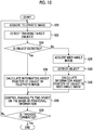
- Fig. 10 is a flowchart illustrating another example of the auto-tracking control method in the auto-tracking imaging apparatus according to the present invention, and shows a case where the mode selection section 56 selects the second tracking mode.
- the first object detection section 52 acquires the telephoto image from the image acquisition section 22 (step S20), and detects the tracking target object from the acquired telephoto image (step S22).
- step S22 it is determined whether the first object detection section 52 detect the object, in step S22 (step S24). In a case where the object is detected (in a case of "Yes"), the first object detection section 52 calculates the information about the position of the detected object in the telephoto image (step S26).
- step S28 the process advances to step S28, and the second object detection section 54 performs processing of steps S28 to S32.
- the processing of steps S28 to S32 is the same as processing of steps S10 to S14 shown in Fig. 9 . That is, the second object detection section 54 acquires the wide-angle image from the image acquisition section 22 (step S28), detects the tracking target object from the acquired wide-angle image (step S30), and calculates the information about the position of the detected object in the wide-angle image (step S32).
- the panning/tilting control section 60 inputs the information about the position of the object detected in step S26 in the telephoto image or the information about the position of the object detected in step S32 in the wide-angle image, and controls the panning/tilting device 30 such that the object is at the center position in the telephoto image or at the center position in the wide-angle image, on the basis of the input positional information (step S34).
- the control of the panning/tilting device 30 performed by the panning/tilting control section 60 in a case where the first object detection section 52 detects the object on the basis of the telephoto image, the control of the panning/tilting device 30 is prioritized on the basis of the information about the position of the object in the telephoto image.
- step S36 it is determined whether or not the auto-tracking imaging is terminated. If it is determined that the imaging is not terminated, the current process advances to step S20. Thereby, the processes of steps S20 to S36 are repeated, and the object is automatically tracked and imaged. In contrast, if it is determined that the auto-tracking imaging is terminated, the auto-tracking imaging is terminated.
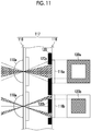
- Fig. 11 is a side view illustrating another embodiment of the directional sensor.
- a directional sensor 117 includes a micro lens array 118 as pupil division means, a light blocking member 120 that functions as a light blocking mask, and an image sensor 116 in which the light receiving cells 116a and 116b are partially blocked by the light blocking member 120.
- the light receiving cells 116a and 116b, which are partially blocked by the light blocking member 120 are provided alternately (in a checker flag shape) in the left-right direction and up-down direction of the image sensor 116.
- the micro lens array 118 has micro lenses 118a corresponding one-to-one with the light receiving cells 116a and 116b of the image sensor 116.
- the light blocking member 120 is configured to regulate the openings of the light receiving cells 116a and 116b of the image sensor 116, and the openings have opening shapes corresponding to the central optical system 13 and annular optical system 14 of the imaging optical system 12 shown in Fig. 2 .
- color filters of red (R), green (G), and blue (B) are arranged under the lenses of the micro lens array 118.
- the circumferential portion of the opening of the light receiving cell 116a is shielded from light by the light blocking section 120a of the light blocking member 120, while the central portion of the opening of the light receiving cell 116b is shielded from light by the light blocking section 120b of the light blocking member 120.
- rays passing through the central optical system 13 of the imaging optical system 12 are pupil-divided by the light blocking section 120a of the light blocking member 120 and the micro lens array 118, and are incident onto the light receiving cell 116a
- rays passing through the annular optical system 14 of the imaging optical system 12 are pupil-divided by the light blocking section 120b of the light blocking member 120 and the micro lens array 118, and are incident onto the light receiving cell 116b.
- a pixel signal of the wide-angle image can be read from the each light receiving cell 116a of the image sensor 116, and a pixel signal of the telephoto image can be read from each light receiving cell 116b of the image sensor 116.
- Fig. 12 is a sectional view illustrating another embodiment of the imaging section that can be applied to the auto-tracking imaging apparatus 10.
- the imaging section includes an imaging optical system 112 and the directional sensor 17.
- the directional sensor 17 is the same as those shown in Figs. 2 and 3 , and hereinafter the imaging optical system 112 will be described.
- the imaging optical system 112 is formed of a central optical system 113 at the central portion and an annular optical system 114 at the periphery. The systems are disposed on the same optical axis.
- the central optical system 113 is a telephoto optical system formed of a first lens 113a, a second lens 113b, and a common lens 115, and has an angle of view ⁇ .
- the annular optical system 114 is a wide-angle optical system formed of a lens 114a and a common lens 115, and has angle of view ⁇ ( ⁇ > ⁇ ), and the angle of view ⁇ is greater than that of the central optical system 113.
- the imaging optical system 112 is different in that the system does not use a reflection mirror, the central optical system 113 is a telephoto optical system, and the annular optical system 114 is a wide-angle optical system.
- the panning/tilting mechanism 32 which rotates the imaging section 11 in the panning direction and the tilting direction, is provided in the apparatus main body 2.
- the present invention is not limited to this, and the entire imaging apparatus may be mounted on an electric pan head (panning/tilting device).
- the auto-tracking imaging apparatus according to the present invention can be used as, for example, a surveillance camera, or an on-board camera.
- the tracking target object may be initially set by an operator using a touch panel or the like on the basis of the wide-angle image which is displayed on the display section 44.
- the second optical system provided at the periphery of the first optical system is the annular optical system.
- the present invention is not limited to this, and the second optical system may be formed of a plurality of optical systems arranged concentrically around the optical axis.
- the reflection mirror in the reflection-mirror-type lens configuration of the imaging optical system 12 shown in Fig. 2 is not limited to a concave mirror or a convex mirror, and may be a plane mirror. Further, the number of reflection mirrors is not limited to two, and may be equal to or greater than three.
- the focus adjustment section may move the common lens or the image sensor of the central optical system and the annular optical system in the optical axis direction.
Description
- The present invention relates to an auto-tracking imaging apparatus, and particularly relates to an auto-tracking imaging apparatus capable of simultaneously capturing a wide-angle image and a telephoto image.
-
US 6,734,911 B1 teaches a tracking system that provides high resolution images and a low tracking dropout rate. -
WO 2013/027488 A1 is a PCT application. It discloses an bifocal optical system with a telephoto lens in a central position and a wide-angle lens at the periphery. It also discloses a microlens array in front of a light shielding member that divides the rays from the bifocal optical system into a wide-angle image and a telephoto image on the pixels of a sensor. -
JP1999-69342A JP-H11-69342A JP2006-33224A - Both the systems described in
JP1999-69342A JP-H11-69342A JP2006-33224A - Further, a tracking system in which a camera is mounted on a panning/tilting mount, and which controls the panning/tilting mount such that it captures an object (OBT) subjected to tracking at the center of the field of view of the camera has been proposed. The camera comprises an optical system in which an axis of a narrow-angle lens portion of a central circular part coincides with an axis of a wide-angle lens portion of an annular part surrounding the central circular part, and an image sensor having a central zone, in which a narrow-angle image is formed by the narrow-angle lens portion, and a circumferential zone in which a wide-angle image is formed by the wide-angle lens portion (
JP2003-510666A - Thereby, even if the OBT drops out from the narrow-angle image, the OBT can be captured by using the wide-angle image. Thus, tracking dropout does not occur.
- Further, a contact lens, through which the wide-angle and telephoto images can be observed, was proposed by Joseph Ford at the University of California at San Diego (UCSD) ("Photonic Systems Integration Laboratory", the Internet <URL: http:// psilab.ucsd.edu/research/Telescopic Contact Lens/main.html>).
- By using the configuration of the contact lens in a camera, it is possible to obtain wide-angle and telephoto images.
- Both systems described in
JP1999-69342A JP-H11-69342A JP2006-33224A - On the other hand, in the tracking system described in
JP2003-510666A - That is, on an image sensor, overlapping (butting) between the narrow-angle image and the wide-angle image occurs. In order to avoid the above-mentioned problem, if an optical blocking and separating mechanism is provided, the wide-angle image is formed in an annular shape, and the center part of the wide-angle image is vacant. Accordingly, imaging cannot be performed.
- Further, in a case where the central circular part is formed as a telephoto lens and the annular part is formed as a wide-angle lens, it is difficult to design an optical system that smoothly connects the narrow-angle and wide-angle images which are captured through these lenses. In this situation, at the boundary between the telephoto image and the wide-angle image, a region, in which an image is not captured, appears.
- The contact lens described in "Photonic Systems Integration Laboratory", the Internet <URL: http:// psilab.ucsd.edu/research/Telescopic Contact Lens/main.html> is able to solve the problem of parallax between the wide-angle image and the telephoto image. However, in order to separately obtain two images which are wide-angle and telephoto images, a switching shutter is necessary. For this reason, a complex system is formed. Further, it is not possible to obtain both images at the same time, and thus information of the wide-angle image is not acquired while the telephoto image is being acquired. Accordingly, there is a problem in that precision of tracking is lowered.
- The present invention has been made in consideration of the above-mentioned situation, and its object is to provide a small-size and inexpensive auto-tracking imaging apparatus capable of simultaneously acquiring wide-angle and telephoto images, of which the optical axes coincide with each other, through a single imaging section, and reliably capturing the tracking target object by using the telephoto image.
- In order to achieve the above-mentioned object, according to an aspect of the present invention, there is provided an auto-tracking imaging apparatus comprising: an imaging optical system that is formed of a first optical system at a central portion thereof and a second optical system which is provided at the periphery of the first optical system and has an optical axis the same as that of the first optical system, where one of the optical systems is a wide-angle optical system, and the other is a telephoto optical system; a directional sensor that has a plurality of pixels constituted of photoelectric conversion elements two-dimensionally arranged and that respectively pupil-divides rays incident through the wide-angle and telephoto optical systems so as to selectively receive the rays; a panning/tilting mechanism that rotates an imaging section, which includes the imaging optical system and the directional sensor, in horizontal and vertical directions; an image acquisition section that respectively acquires a wide-angle image, for which light is received from the directional sensor through the wide-angle optical system, and a telephoto image for which light is received from the directional sensor through the telephoto optical system; an object detection section that detects a tracking target object on the basis of at least the wide-angle image in the wide-angle and telephoto images acquired by the image acquisition section; and a panning/tilting control section that controls the panning/tilting mechanism on the basis of information about a position of the object, which is detected by the object detection section, in the image.
- According to the aspect of the present invention, it is possible to simultaneously acquire the wide-angle and telephoto images having a common optical axis through the imaging section (single imaging section) including the directional sensor and the imaging optical system having the above-mentioned configuration. Thus, the tracking target object is detected on the basis of at least the wide-angle image, and the panning/tilting mechanism is controlled on the basis of the information about the position of the detected object in the image, whereby the object is set to be within the telephoto image (to be automatically tracked). Further, even if the object moves at a high speed, it is possible to capture the object by using the wide-angle image. As a result, there is no tracking dropout.
- It is preferable that the auto-tracking imaging apparatus according to another aspect of the present invention further comprises a recording section that records at least the telephoto image in the wide-angle and telephoto images acquired by the image acquisition section. Thereby, a desired object can be checked on the basis of the telephoto image which is recorded by the recording section.
- In the auto-tracking imaging apparatus according to still another aspect of the present invention, it is preferable that the object detection section detects a moving object on the basis of at least the wide-angle image in the wide-angle and telephoto images continuously acquired by the image acquisition section, and sets the detected moving object as the tracking target object. Since the tracking target object is moving, it is possible to detect a desired object through detection of the moving object.
- In the auto-tracking imaging apparatus according to still another aspect of the present invention, it is preferable that the object detection section recognizes a specific object on the basis of at least the wide-angle image in the wide-angle and telephoto images acquired by the image acquisition section, and sets the recognized specific object as the tracking target object. For example, in a case where the specific object is a person, by recognizing the person or a face of the person, it is possible to detect the tracking target object.
- In the auto-tracking imaging apparatus according to still another aspect of the present invention, the panning/tilting control section controls the panning/tilting mechanism on the basis of the information about the position of the object, which is detected by the object detection section, in the image, and an angle of view of at least the telephoto image is set to include the detected object. In this case, the panning/tilting mechanism may be controlled such that the detected object is at the center of the telephoto image, and the panning/tilting mechanism may be controlled such that the detected object is within a predetermined range in the vicinity of the center of the telephoto image.
- In the auto-tracking imaging apparatus according to still another aspect of the present invention, it is preferable that the object detection section has a first object detection section that detects the object on the basis of the telephoto image acquired by the image acquisition section, and a second object detection section that detects the object on the basis of the wide-angle image acquired by the image acquisition section. In addition, it is preferable that the panning/tilting control section controls the panning/tilting mechanism on the basis of the information about a position of the object, which is detected by the first object detection section, in the telephoto image, and controls the panning/tilting mechanism on the basis of the information about a position of the object, which is detected by the second object detection section, in the wide-angle image when the first object detection section is unable to detect the object.
- According to the above-mentioned aspect of the present invention, in a case where the object can be detected on the basis of the telephoto image, the panning/tilting mechanism is controlled on the basis of the information about the position of the detected object in the telephoto image. Thus, it is possible to precisely perform auto-tracking. In contrast, in a case where the object cannot be detected on the basis of the telephoto image, the panning/tilting mechanism is controlled on the basis of the wide-angle image, that is, on the basis of the information about the position of the detected object in the wide-angle image. Thereby, as compared with the control of the panning/tilting mechanism based on the information about the position in the telephoto image, the precision of the auto-tracking is lowered. However, there is no tracking dropout.
- It is preferable that the auto-tracking imaging apparatus according to still another aspect of the present invention further comprises a mode selection section that selects a first tracking mode or a second tracking mode. In addition, it is preferable that the panning/tilting control section controls the panning/tilting mechanism on the basis of only the information about the position of the object detected by the second object detection section in the wide-angle image if the mode selection section selects the first tracking mode, controls the panning/tilting mechanism on the basis of the information about the position of the object detected by the first object detection section in the telephoto image if the mode selection section selects the second tracking mode, and controls the panning/tilting mechanism on the basis of the information about the position of the object detected by the second object detection section in the wide-angle image when the first object detection section is unable to detect the object.
- Thereby, it is possible to selectively use auto-tracking imaging using the first tracking mode and auto-tracking imaging using the second tracking mode in accordance with the use.
- In the auto-tracking imaging apparatus according to still another aspect of the present invention, it is preferable that the first optical system of the imaging optical system is a central optical system that has a circular shape, and the second optical system is an annular optical system that is disposed concentrically around the central optical system. No parallax occurs between the two images captured by the central optical system, which have a circular shape, and the annular optical system which is disposed concentrically around the central optical system. Further, each of the optical systems is rotationally symmetric, and thus preferred as an imaging optical system.
- In the auto-tracking imaging apparatus according to still another aspect of the present invention, it is preferable that the annular optical system has a reflective optical system that reflects rays twice or more. Thereby, it is possible to shorten the dimension of the annular optical system in the optical axis direction. As a result, it is possible to reduce the size of the imaging section.
- In the auto-tracking imaging apparatus according to still another aspect of the present invention, it is preferable that the first optical system is the wide-angle optical system, and the second optical system is the telephoto optical system.
- It is preferable that the auto-tracking imaging apparatus according to still another aspect of the present invention further includes a focus adjustment section that performs focus adjustment of the telephoto optical system. Since the telephoto optical system has a depth of field lower than that of the wide-angle optical system and blurring tends to occur in the telephoto optical system, it is preferable that the focus adjustment is performed thereon. It should be noted that the focus adjustment section may be provided also in the wide-angle optical system, and the wide-angle optical system may perform panning and focusing without the focus adjustment section in the wide-angle optical system.
- In the auto-tracking imaging apparatus according to still another aspect of the present invention, the directional sensor may have a micro lens array or a light blocking mask that functions as pupil division means.
- According to the present invention, it is possible to simultaneously acquire wide-angle and telephoto images, of which the optical axes coincide with each other, through a single imaging section, and thus it is possible to reduce the size and the cost of the auto-tracking imaging apparatus. Further, the optical axis directions of the wide-angle and telephoto images coincide with each other. Thus, the tracking target object is detected on the basis of at least the wide-angle image, and the panning/tilting mechanism is controlled on the basis of the information about the position of the detected object in the image, whereby the object can be set to be within the telephoto image (to be automatically tracked). Further, even if the object moves at a high speed, it is possible to capture the object by using the wide-angle image. As a result, there is an effect that no tracking dropout occurs.
-
-
Fig. 1 is a perspective view of an appearance of an auto-tracking imaging apparatus according to the present invention. -
Fig. 2 is a sectional view illustrating a first embodiment of an imaging section of the auto-tracking imaging apparatus. -
Fig. 3 is an enlarged view of principal sections of a micro lens array and an image sensor shown inFig. 2 . -
Figs. 4A to 4C2 are diagrams illustrating a color filter array and the like which are disposed in the image sensor. -
Fig. 5 is a block diagram illustrating an embodiment of an internal configuration of the auto-tracking imaging apparatus. -
Figs. 6A and 6B are diagrams illustrating examples of the wide-angle and telephoto images captured by the auto-tracking imaging apparatus. -
Fig. 7 is an image diagram illustrating a telephoto image that indicates a state where tracking is controlled such that a specific object (a face of a person) is at the center of the telephoto image. -
Figs. 8A to 8C are diagrams illustrating an example of a moving object detection method for detecting a moving object as a tracking target object. -
Fig. 9 is a flowchart illustrating an example of an auto-tracking control method using the auto-tracking imaging apparatus according to the present invention. -
Fig. 10 is a flowchart illustrating another example of the auto-tracking control method using the auto-tracking imaging apparatus according to the present invention. -
Fig. 11 is a side view illustrating another embodiment of a directional sensor. -
Fig. 12 is a sectional view illustrating another embodiment of the imaging section that can be applied to the auto-tracking imaging apparatus. - Hereinafter, referring to accompanying drawings, embodiments of an auto-tracking imaging apparatus according to the present invention will be described.
-
Fig. 1 is a perspective view of an appearance of an auto-tracking imaging apparatus according to the present invention. - As shown in
Fig. 1 , an auto-tracking imaging apparatus 10 mainly has an apparatusmain body 2, animaging section 11, a panning/tilting device 30 (Fig. 5 ), and a dome cover 6 that covers theimaging section 11. - The panning/
tilting device 30 has apedestal 4 and aholding section 8 that is fixed onto thepedestal 4 and rotatably holds theimaging section 11. - The
pedestal 4 is disposed to be rotatable about the axis of the vertical direction Z of the apparatusmain body 2. A pan driving section 34 (Fig. 5 ) rotates about the axis of the vertical direction Z. - The holding
section 8 has agear 8A that is provided on the axis the same as the axis of the horizontal direction X, and transfers the driving force from the tilt driving section 36 (Fig. 5 ) through thegear 8A, thereby rotating (tilting) theimaging section 11 in the up-down direction. - The dome cover 6 is a vibration-proof and drip-proof cover. It is preferable that the dome cover 6 has a spherical shell shape with a certain thickness at which an intersection point between the axis of the horizontal direction X and the axis of the vertical direction Z is set as a center of a curvature thereof without change in optical performance of the
imaging section 11, regardless of an optical axis direction L of theimaging section 11. - Further, it is preferable that a tripod attaching section (such as a tripod screw hole) not shown in the drawing is provided on the rear surface of the apparatus
main body 2. -
Fig. 2 is a sectional view illustrating a first embodiment of theimaging section 11 of the auto-tracking imaging apparatus 10. - As shown in
Fig. 2 , theimaging section 11 includes the imagingoptical system 12 and thedirectional sensor 17. - The imaging
optical system 12 includes a centraloptical system 13 as a first optical system at the center portion and an annularoptical system 14 as a second optical system having a concentric shape at the periphery. Each optical system is disposed on the same optical axis. - The central
optical system 13 is a wide-angle optical system (wide-angle lens) including afirst lens 13a, asecond lens 13b, athird lens 13c, afourth lens 13d, and acommon lens 15, and forms a wide-angle image on amicro lens array 16 constituting thedirectional sensor 17. - The annular
optical system 14 is a telephoto optical system (telephoto lens) including afirst lens 14a, asecond lens 14b, afirst reflection mirror 14c as a reflective optical system, asecond reflection mirror 14d, and acommon lens 15, and forms a telephoto image on amicro lens array 16. Rays, which are incident through thefirst lens 14a and thesecond lens 14b, are reflected twice by thefirst reflection mirror 14c and thesecond reflection mirror 14d, and thereafter pass through thecommon lens 15. The rays are bent by thefirst reflection mirror 14c and thesecond reflection mirror 14d, whereby a length of the telephoto optical system (telephoto lens) having a long focal length in the optical axis direction is shortened. - The
directional sensor 17 includes amicro lens array 16 and animage sensor 18. -
Fig. 3 is an enlarged view of principal sections of themicro lens array 16 and theimage sensor 18. - The
micro lens array 16 is configured such that multiple micro lenses (pupil imaging lenses) 16a are two-dimensionally arranged. Distances between the micro lenses in the horizontal and vertical directions correspond to distances between three light receivingcells 18a as photoelectric conversion elements of theimage sensor 18. That is, each micro lens of themicro lens array 16 is formed to correspond to positions of two light receiving cells in each direction of the horizontal and vertical directions. - Further, each
micro lens 16a of themicro lens array 16 forms a central pupil image (first pupil image) 17a having a circular shape and annular pupil image (second pupil image) 17b, which correspond to the centraloptical system 13 and the annularoptical system 14 of the imagingoptical system 12, on the light receivingcells 18a in a corresponding light receiving region of theimage sensor 18. - According to the
micro lens array 16 and theimage sensor 18 shown inFig. 3 , 3×3 light receivingcells 18a having a lattice (square lattice) shape are allocated for each onemicro lens 16a of themicro lens array 16. Hereinafter, a light receiving cell group (3×3 light receivingcells 18a) corresponding to onemicro lens 16a and onemicro lens 16a is referred to as a unit block. - The
central pupil image 17a is formed only on thelight receiving cell 18a at the center of the unit block, and theannular pupil image 17b is formed on the eight light receivingcells 18a at the periphery of the unit block. - According to the
imaging section 11 having the above-mentioned configuration, as described later, a wide-angle image corresponding to the centraloptical system 13 and a telephoto image corresponding to the annularoptical system 14 are captured at the same time. -
Figs. 4A to 4C2 are diagrams illustrating a color filter array that is disposed on theimage sensor 18. InFigs. 4A to 4C2 , themicro lens array 16 is omitted, but the regions indicated by circles represents unit blocks each including 3×3 light receiving cells on which pupil images are formed by the respectivemicro lenses 16a of themicro lens array 16. - As shown in
Fig. 4A , the color filter array formed of color filters disposed on the respective light receiving cells is provided on an imaging surface of theimage sensor 18. - The color filter array is formed of color filters (hereinafter referred to as R, G, and B filters) which have three primary colors and through which rays with respective wavelength regions of red (R), green (G), and blue (B) are transmitted. Then, any one of the RGB filters is disposed on each light receiving cell. Hereinafter, the light receiving cell, on which the R filter is disposed, is referred to as an "R light receiving cell", the light receiving cell, on which the G filter is disposed, is referred to as an "G light receiving cell", and the light receiving cell, on which the B filter is disposed, is referred to as an "B light receiving cell".
- The color filter array shown in
Fig. 4A is configured as follows: 6×6 light receiving cells are set as a basic block B (a block indicated by a large frame ofFig. 4A , and shown inFig. 4B ), and the basic blocks B are repeatedly arranged in the horizontal and vertical directions. - As shown in
Fig. 4B , the basic block B is formed of four unit blocks B1 to B4. -
Fig. 4C1 shows a group of central light receiving cells (light receiving cells on which rays passing through the centraloptical system 13 shown inFig. 3 are incident) of the four unit blocks B1 to B4.Fig. 4C2 shows groups of eight peripheral light receiving cells (light receiving cells on which rays passing through the annularoptical system 14 shown inFig. 3 are incident). - As shown in
Fig. 4C1 , the image of the group of the central light receiving cells is formed of mosaic images having a Bayer array. Thereby, by performing the demosaic processing on the mosaic images having the Bayer array, it is possible to obtain a color image. - In contrast, as shown in
Fig. 4C2 , the groups of the central light receiving cells and the eight peripheral light receiving cells of the unit blocks B1 to B4 include all the RGB light receiving cells (R, G, and B light receiving cells) in the eight light receiving cells, and the RGB light receiving cells are arranged with the same pattern regardless of the unit blocks B1 to B4. - Specifically, G light receiving cells are disposed on the four light receiving cells at four corners of each of the unit blocks B1 to B4, R light receiving cells are disposed on the two upper and lower light receiving cells with the central light receiving cell interposed therebetween, and B light receiving cells are disposed on the two left and right light receiving cells with the central light receiving cell interposed therebetween.
- Further, the R light receiving cells, the G light receiving cells, and the B light receiving cells are respectively positioned to be symmetric to each other with respect to the central light receiving cell (center) of each unit block. Thereby, by using output signals of the RGB light receiving cells in the unit blocks, after the demosaic processing (synchronization processing) of each unit block, one pixel (a pixel value of RGB) constituting an image can be generated.
- That is, by obtaining an average value of the output signals (pixel values) of the four G light receiving cells within the unit block, it is possible to acquire a pixel value of the G pixel at the center of the unit block (single micro lens). Likewise, by obtaining an average value of the pixel values of the two R light receiving cells and an average value of the pixel values of the two B light receiving cells within the unit block, it is possible to acquire respective pixel values of the R and B pixels at the center of the unit block.
- Thereby, the telephoto image, which is generated by a group of the peripheral eight light receiving cells of each unit block and corresponds to the annular optical system 14 (telephoto optical system), can be subjected to demosaic processing on the basis of pixel values of the RGB light receiving cells within the unit block. Thus, by interpolating the pixel values of the light receiving cells of the peripheral unit blocks, it is not necessary to generate pixel values of pixels in a specific wavelength region, and there is no deterioration in resolution (substantial number of pixels).
-
Fig. 5 is a block diagram illustrating an embodiment of an internal configuration of the auto-tracking imaging apparatus 10. - As shown in
Fig. 5 , the auto-tracking imaging apparatus 10 comprises theimaging section 11 that is formed of the imagingoptical system 12, which has the centraloptical system 13 and the annularoptical system 14 described inFig. 2 and thedirectional sensor 17 which has themicro lens array 16 and theimage sensor 18 described inFigs. 3 and4A to 4C2 . - It is preferable that the
imaging section 11 comprises afocus adjustment section 19 that performs focus adjustment of the telephoto optical system (annular optical system 14). Thefocus adjustment section 19 can be constituted of, for example, a voice coil motor that moves an entire or partial optical system of the annularoptical system 14 in the optical axis direction, and the like. Further, determination as to whether or not the telephoto image is in an in-focus state can be performed on the basis of a contrast of a focus detection region of the telephoto image. However, the focus adjustment method is not limited to this. In addition, in the wide-angle optical system (central optical system 13), the focus adjustment section may be separately provided, and the panning and focusing function may be used. - The panning/tilting device (electric pan head) 30 comprises, as shown in
Fig. 1 , a panning mechanism that rotates theimaging section 11 in the horizontal direction (panning direction) of the apparatusmain body 2, and a panning/tilting mechanism (hereinafter referred to as a "panning/tilting mechanism") 32 that rotates theimaging section 11 in the vertical direction (tilting direction), apan driving section 34, atilt driving section 36, and the like. The panning/tilting mechanism 32 has a home position sensor that detects a reference position of a rotation angle (pan angle) in the panning direction and a home position sensor that detects a reference position of an inclination angle (tilt angle) in the tilting direction. - Each of the
pan driving section 34 and thetilt driving section 36 has a stepping motor and a motor driver, outputs a driving force to a panning/tilting mechanism 32, and drives the panning/tilting mechanism 32. - The
imaging section 11 captures time-series wide-angle and telephoto images through the imagingoptical system 12 and thedirectional sensor 17, and converts subject images into signal voltages (or electric charges) of which amounts correspond to an amount of incident light. The subject images are formed on light receiving surfaces of the light receiving cells (photoelectric conversion elements) of the directional sensor 17 (image sensor 18) through the imagingoptical system 12. - The signal voltages (or electric charges) accumulated in the
image sensor 18 can be stored in the light receiving cells themselves or provided capacitors. The stored signal voltages (or electric charges) are read in conjunction with selection of positions of the light receiving cells by a method of using MOS-type imaging elements (so-called CMOS sensors) based on an X-Y address system. - Thereby, pixel signals, which indicate wide-angle images of groups of the central light receiving cells corresponding to the central
optical system 13, and pixel signals, which indicate telephoto images of groups of the eight peripheral light receiving cells corresponding to the annularoptical system 14, can be read from theimage sensor 18. In addition, pixel signals, which indicate the wide-angle and telephoto images, are continuously read from theimage sensor 18, at a predetermined frame rate (for example, a frame number per sec. of 24p, 30p, or 60p). - The pixel signal (voltage signals), which is read from the
image sensor 18, for each light receiving cell is sampled through correlated double sampling processing (processing of acquiring precise pixel data by taking a difference between a feed-through component level and a signal component level included in the output signal of each light receiving cell in order to reduce noise (particularly thermal noise) included in the sensor output signal). Then, the signal is amplified, and thereafter added to an A/D converter 20. The A/D converter 20 converts the pixel signals, which are sequentially input, into digital signals, and outputs the signals to theimage acquisition section 22. In addition, the A/D converter may be built into the MOS-type sensor. In this case, the digital signals are output directly from theimage sensor 18. - The
image acquisition section 22 selects the positions of the light receiving cells of theimage sensor 18 and reads the pixel signals, thereby simultaneously or selectively acquiring the pixel signals, which indicate the wide-angle image, and the pixel signals which indicate the telephoto image. - That is, by selectively reading the pixel signals of the light receiving cells of the
image sensor 18 onto which thecentral pupil images 17a are incident, it is possible to acquire the pixel signals (pixel signals indicating mosaic images having a Bayer array) indicating a wide-angle image of the light receiving cells (each of which is the central light receiving cell of the 3×3 light receiving cells) each of which corresponds to each one micro lens. In contrast, by selectively reading the pixel signals of the light receiving cells of theimage sensor 18 onto which theannular pupil images 17b are incident, it is possible to acquire the pixel signals (pixel signals indicating mosaic images having a Bayer array) indicating a telephoto image of the light receiving cells (which are the peripheral light receiving cells of the 3×3 light receiving cells) of which every eight light receiving cells correspond to each one micro lens. - In addition, all the pixel signals may be read from the
image sensor 18 and temporarily stored in the buffer memory, and groups of the pixel signals of the two images of the wide-angle and telephoto images may be divided from the pixel signals stored in the buffer memory. - The pixel signals, which indicate the wide-angle and telephoto images acquired by the
image acquisition section 22, are respectively output to a digitalsignal processing section 40 and anobject detection section 50. - The digital
signal processing section 40 performs predetermined signal processing, such as offset processing, gamma correction processing, and demosaic processing for the signals of the RGB mosaic images, on the input digital pixel signals (sequential R, G, and B signals of RGB points). Here, the demosaic processing is processing of calculating information of all colors for each pixel from the RGB mosaic images corresponding to a color filter array of a single-plate-type image sensor 18, and is also referred to as synchronization processing. For example, in the case of theimage sensor 18 having color filters of three colors of RGB, the demosaic processing is processing of calculating information of all colors of RGB for each pixel from the mosaic images having RGB colors. - That is, the demosaic processing section included in the digital
signal processing section 40 does not have the R and B light receiving cells at the positions of the G light receiving cells of the wide-angle image (mosaic images having a Bayer array). Hence, the R and B signals of the R and B light receiving cells around the G light receiving cells are separately interpolated, and the R and B signals at the positions of the G light receiving cells are generated. Likewise, at the positions of the R light receiving cells of the mosaic images, there are no G and B light receiving cells. Hence, the G and B signals of the G and B light receiving cells around the R light receiving cells are separately interpolated, and the G and B signals at the positions of the R light receiving cells are generated. Further, at the positions of the B light receiving cells of the mosaic images, there are no G and R light receiving cells. Hence, the G and R signals of the G and R light receiving cells around the B light receiving cells are separately interpolated, and the G and R signals at the positions of the B light receiving cells are generated. - In contrast, as shown in
Fig. 4C2 , the telephoto image is formed of the mosaic images of which every eight (eight peripheral blocks of 3x3 unit blocks) images correspond to onemicro lens 16a, and the eight light receiving cells include all RGB color information pieces (of the R, G, and B light receiving cells). Accordingly, the demosaic processing section is able to generate a single pixel (RGB pixel value) constituting the image, on which the demosaic processing is performed, for each unit block, by using the output signals of the eight light receiving cells in the unit block. - Specifically, the demosaic processing section, which performs the demosaic processing on the mosaic images of the telephoto image, calculates an average value of the pixel values of the four G light receiving cells in the unit block, thereby calculating a G pixel value of the pixel at the center position of the unit block (single micro lens). Likewise, the demosaic processing section calculates an average value of the pixel values of the two R light receiving cells and an average value of the pixel values of the two B light receiving cells in the unit block, thereby calculating R and B pixel values of the pixels at the center positions of the respective unit blocks.
- The demosaic image of the telephoto image of two demosaic images of the wide-angle and telephoto images generated by the demosaic processing section is subjected to demosaic processing by using the output signals of the eight light receiving cells in the unit block. Accordingly, the resolution of the demosaic image is substantially higher than that of the demosaic image of the wide-angle image which is subjected to demosaic processing by using (interpolating) the output signals of the light receiving cells of the peripheral unit blocks.
- Further, the digital
signal processing section 40 performs RGB/YC conversion or the like which generates a luminance signal Y and color difference signals Cb and Cr from the RGB color information pieces (R, G, and B signals) on which demosaic processing is performed by the demosaic processing section, thereby generating image signals for recording and displaying a moving image indicating the wide-angle and telephoto images with the predetermined frame rate. - The image signals, which indicate the wide-angle and telephoto images processed by the digital
signal processing section 40, are respectively output to therecording section 42 and thedisplay section 44. Therecording section 42 records the image signals for recording a moving image indicating the wide-angle and telephoto images processed by the digitalsignal processing section 40 in a recording medium (such as a hard disk or a memory card). In addition, therecording section 42 may record only the telephoto image. - The
display section 44 displays the wide-angle and telephoto images on the basis of the image signals for displaying the moving image indicating the wide-angle and telephoto images processed by the digitalsignal processing section 40. In addition, thedisplay section 44 may reproduce the wide-angle and telephoto images on the basis of the image signals recorded in therecording section 42. - In contrast, the
object detection section 50 has: a firstobject detection section 52 that detects a tracking target object on the basis of the pixel signals indicating the wide-angle and telephoto images acquired by theimage acquisition section 22, outputs the information about the position of the detected object in the image to the panning/tilting control section 60, detects the object on the basis of the telephoto image, and detects the information about the position of the object in the telephoto image; and a secondobject detection section 54 that detects the object on the basis of the wide-angle image, and detects the information about the position of the object in the wide-angle image. - As the object detection method in the first
object detection section 52 and secondobject detection section 54, there is a method of detecting a specific object on the basis of an object recognition technology as a representative of a technology for recognizing a person's face, or a moving object detection method of detecting a moving object as a tracking target object. - The object detection method based on object recognition is a method in which features of a specific object in a viewing direction are registered as an object dictionary in advance and an object is recognized by comparing the object dictionary with a clipped image while changing a position or a size of the object from the captured image.
-
Figs. 6A and 6B are diagrams respectively illustrating examples of captured wide-angle and telephoto images. In addition, the region indicated by the dashed line within the wide-angle image represents an imaging range of the telephoto image. - At this time, the wide-angle and telephoto images shown in
Figs. 6A and 6B are captured, a person's face is set as a tracking target, and the person's face is detected by using an object (face) recognition technology. In this case, the secondobject detection section 54 is able to detect the face, but the firstobject detection section 52 is unable to detect the face. The reason for this is that telephoto image includes only a part of the person's face, and thus face cannot be recognized. - Accordingly, in this case, the second
object detection section 54 outputs information about a position of the detected person's face (object) in the wide-angle image to the panning/tilting control section 60. - In contrast, in a case where the first
object detection section 52 detects the object on the basis of the telephoto image, the firstobject detection section 52 outputs information about a position of the detected object in the telephoto image to the panning/tilting control section 60 in priority to the information about the position of the object, which is detected by the secondobject detection section 54, in the wide-angle image. The reason for this is that the firstobject detection section 52 has a higher accuracy in detecting the position of the object than the secondobject detection section 54. - Further, in the present example, a
mode selection section 56, which selects a first tracking mode or a second tracking mode, is provided. The first tracking mode is a mode for outputting only the information about the position of the object detected by the secondobject detection section 54 in the wide-angle image to the panning/tilting control section 60 and controlling the panning/tilting device 30 on the basis of the information about the position in the wide-angle image. On the other hand, the second tracking mode is a mode that uses the firstobject detection section 52 and the secondobject detection section 54 in combination. In this mode, in a case where the firstobject detection section 52 detects the object, the information about the position of the object in the telephoto image is preferentially output to the panning/tilting control section 60, and the panning/tilting device 30 is controlled on the basis of the information about the position in the telephoto image. In a case where the firstobject detection section 52 does not detect the object, the information about the position of the object detected by the secondobject detection section 54 in the wide-angle image is output to the panning/tilting control section 60, and the panning/tilting device 30 is controlled on the basis of the information about the position of the object in the wide-angle image. - The panning/
tilting control section 60 is a section that controls the panning/tilting device 30 on the basis of the information about the position of the object in the image (in the wide-angle image or the telephoto image) which is input from theobject detection section 50 as described above. The panning/tilting control section 60 controls the panning/tilting mechanism 32 (that is, a direction of imaging performed by the imaging section 11) through thepan driving section 34 and thetilt driving section 36 such that the information about the position (for example, a barycentric position of a face region in a case where the tracking target is a face) of the object in the image is moved to the center position (a position on the optical axis) in the image. - Under the control of the panning/
tilting mechanism 32, it is possible to capture an image while automatically tracking a tracking target object (for example, person's face) such that the object is at the centers of the wide-angle and telephoto images.Fig. 7 shows a telephoto image that indicates a state where tracking is controlled such that a specific object (a face of a person) is at the center of the telephoto image. In the present example, the case of controlling tracking such that the position (barycentric position) of the object in the image is at the center of the telephoto image has been described, but the present invention is not limited to this. Thus, the panning/tilting mechanism 32 may be controlled such that the position (barycentric position) of the object in the image is set in at least an angle of view of the telephoto image (preferably, set in a predetermined range (for example, in a focus detection region) in the vicinity of the center of the telephoto image). - Next, as the object detection method of the first
object detection section 52 and secondobject detection section 54, an example of a moving object detection method of detecting a moving object as a tracking target object will be described. - In this case, as shown in
Figs. 8A to 8C , the firstobject detection section 52 detects a difference image (Fig. 8C ) which is obtained from a difference between two time-series telephoto images (a previously acquired telephoto image (Fig. 8A ) and a currently acquired telephoto image (Fig. 8B ). - In the examples shown in
Figs. 8A and 8B , the object A of the objects A and B moves, and the object B remains stationary. - Accordingly, as shown in
Fig. 8C , the difference images A1 and A2 are images generated through movement of the object A. - Here, the barycentric positions of the difference images A1 and A2 are calculated, and respectively referred to as positions Pi and P2, and the midpoint of a line segment connecting these positions P1 and P2 is referred to as a position G. In addition, the position G is set as a position of the moving object (object A) in the telephoto image.
- The panning/tilting mechanism 32 (that is, the direction of imaging performed by the imaging section 11) is repeatedly controlled such that the position G of the object A in the telephoto image calculated in such a manner is moved to the center position (the position on the optical axis) in the telephoto image. Thereby, the object A is moved (converged) to the center position in the telephoto image.
- In addition, in a manner similar to that of the first
object detection section 52, the secondobject detection section 54 is also able to detect the position of the object in the wide-angle image by detecting the tracking target object (moving object) on the basis of the wide-angle image. Further, in a case where theimaging section 11 is moved (moved by the panning/tilting mechanism 32, or moved since the auto-tracking imaging apparatus 10 is mounted on a vehicle), background also moves between time-series images. However, in this case, by shifting the images such that backgrounds between the time-series images coincide with each other and acquiring the difference image between the shifted images, regardless of movement of theimaging section 11, it is possible to detect the object which moves in real space. Furthermore, the moving object detection method is not limited to the embodiments. -
Fig. 9 is a flowchart illustrating an example of the auto-tracking control method in the auto-tracking imaging apparatus according to the present invention, and shows a case where themode selection section 56 selects the first tracking mode. - In
Fig. 9 , the secondobject detection section 54 acquires the wide-angle image from the image acquisition section 22 (step S10), and detects the tracking target object from the acquired wide-angle image (step S12). - Subsequently, the second
object detection section 54 calculates the information about the position of the detected object in the wide-angle image (step S14). - Next, the panning/
tilting control section 60 inputs the information about the position of the object in the wide-angle image from the secondobject detection section 54, and controls the panning/tilting device 30 such that the object is at the center of the wide-angle image on the basis of the input positional information (step S16). - Next, it is determined whether or not the auto-tracking imaging is terminated (step S18). If it is determined that the imaging is not terminated, the process advances to step S10. Thereby, the processes of steps S10 to S18 are repeated, and the object is automatically tracked and imaged. In contrast, if it is determined that the auto-tracking imaging is terminated, the auto-tracking imaging is terminated. In addition, determination as to whether or not the auto-tracking imaging is terminated may be performed by turning on/off a power supply, and may be performed on the basis of a switch input indicating whether or not the auto-tracking imaging is performed.
-
Fig. 10 is a flowchart illustrating another example of the auto-tracking control method in the auto-tracking imaging apparatus according to the present invention, and shows a case where themode selection section 56 selects the second tracking mode. - In
Fig. 10 , the firstobject detection section 52 acquires the telephoto image from the image acquisition section 22 (step S20), and detects the tracking target object from the acquired telephoto image (step S22). - Subsequently, it is determined whether the first
object detection section 52 detect the object, in step S22 (step S24). In a case where the object is detected (in a case of "Yes"), the firstobject detection section 52 calculates the information about the position of the detected object in the telephoto image (step S26). - In contrast, in a case where the object is not detected (in a case of "No"), the process advances to step S28, and the second
object detection section 54 performs processing of steps S28 to S32. Here, the processing of steps S28 to S32 is the same as processing of steps S10 to S14 shown inFig. 9 . That is, the secondobject detection section 54 acquires the wide-angle image from the image acquisition section 22 (step S28), detects the tracking target object from the acquired wide-angle image (step S30), and calculates the information about the position of the detected object in the wide-angle image (step S32). - Next, the panning/
tilting control section 60 inputs the information about the position of the object detected in step S26 in the telephoto image or the information about the position of the object detected in step S32 in the wide-angle image, and controls the panning/tilting device 30 such that the object is at the center position in the telephoto image or at the center position in the wide-angle image, on the basis of the input positional information (step S34). In addition, it is needless to say that, in the control of the panning/tilting device 30 performed by the panning/tilting control section 60, in a case where the firstobject detection section 52 detects the object on the basis of the telephoto image, the control of the panning/tilting device 30 is prioritized on the basis of the information about the position of the object in the telephoto image. - Next, it is determined whether or not the auto-tracking imaging is terminated (step S36). If it is determined that the imaging is not terminated, the current process advances to step S20. Thereby, the processes of steps S20 to S36 are repeated, and the object is automatically tracked and imaged. In contrast, if it is determined that the auto-tracking imaging is terminated, the auto-tracking imaging is terminated.
-
Fig. 11 is a side view illustrating another embodiment of the directional sensor. - A
directional sensor 117 includes amicro lens array 118 as pupil division means, alight blocking member 120 that functions as a light blocking mask, and animage sensor 116 in which the light receivingcells light blocking member 120. In addition, the light receivingcells light blocking member 120, are provided alternately (in a checker flag shape) in the left-right direction and up-down direction of theimage sensor 116. - The
micro lens array 118 hasmicro lenses 118a corresponding one-to-one with the light receivingcells image sensor 116. - The
light blocking member 120 is configured to regulate the openings of the light receivingcells image sensor 116, and the openings have opening shapes corresponding to the centraloptical system 13 and annularoptical system 14 of the imagingoptical system 12 shown inFig. 2 . In addition, color filters of red (R), green (G), and blue (B) are arranged under the lenses of themicro lens array 118. - The circumferential portion of the opening of the
light receiving cell 116a is shielded from light by thelight blocking section 120a of thelight blocking member 120, while the central portion of the opening of thelight receiving cell 116b is shielded from light by thelight blocking section 120b of thelight blocking member 120. Thereby, rays passing through the centraloptical system 13 of the imagingoptical system 12 are pupil-divided by thelight blocking section 120a of thelight blocking member 120 and themicro lens array 118, and are incident onto thelight receiving cell 116a, while rays passing through the annularoptical system 14 of the imagingoptical system 12 are pupil-divided by thelight blocking section 120b of thelight blocking member 120 and themicro lens array 118, and are incident onto thelight receiving cell 116b. - Thereby, a pixel signal of the wide-angle image can be read from the each
light receiving cell 116a of theimage sensor 116, and a pixel signal of the telephoto image can be read from each light receivingcell 116b of theimage sensor 116. - Next, another embodiment of the imaging section applied to the auto-tracking imaging apparatus according to the present invention will be described.
-
Fig. 12 is a sectional view illustrating another embodiment of the imaging section that can be applied to the auto-tracking imaging apparatus 10. - The imaging section includes an imaging
optical system 112 and thedirectional sensor 17. In addition, thedirectional sensor 17 is the same as those shown inFigs. 2 and3 , and hereinafter the imagingoptical system 112 will be described. - The imaging
optical system 112 is formed of a centraloptical system 113 at the central portion and an annularoptical system 114 at the periphery. The systems are disposed on the same optical axis. - The central
optical system 113 is a telephoto optical system formed of afirst lens 113a, asecond lens 113b, and acommon lens 115, and has an angle of view α. - The annular
optical system 114 is a wide-angle optical system formed of alens 114a and acommon lens 115, and has angle of view β (β>α), and the angle of view β is greater than that of the centraloptical system 113. - As compared with the imaging
optical system 12 shown inFig. 2 , the imagingoptical system 112 is different in that the system does not use a reflection mirror, the centraloptical system 113 is a telephoto optical system, and the annularoptical system 114 is a wide-angle optical system. - In the auto-tracking imaging apparatus 10 of the present embodiment, the panning/
tilting mechanism 32, which rotates theimaging section 11 in the panning direction and the tilting direction, is provided in the apparatusmain body 2. However, the present invention is not limited to this, and the entire imaging apparatus may be mounted on an electric pan head (panning/tilting device). In addition, the auto-tracking imaging apparatus according to the present invention can be used as, for example, a surveillance camera, or an on-board camera. - Further, the tracking target object may be initially set by an operator using a touch panel or the like on the basis of the wide-angle image which is displayed on the
display section 44. - In the imaging optical system of the present embodiment, the second optical system provided at the periphery of the first optical system is the annular optical system. However, the present invention is not limited to this, and the second optical system may be formed of a plurality of optical systems arranged concentrically around the optical axis.
- The reflection mirror in the reflection-mirror-type lens configuration of the imaging
optical system 12 shown inFig. 2 is not limited to a concave mirror or a convex mirror, and may be a plane mirror. Further, the number of reflection mirrors is not limited to two, and may be equal to or greater than three. - Further, the focus adjustment section may move the common lens or the image sensor of the central optical system and the annular optical system in the optical axis direction.
-
- 10: auto-tracking imaging apparatus
- 11: imaging section
- 12, 112: imaging optical system
- 13, 113: central optical system
- 14, 114: annular optical system
- 16, 118: micro lens array
- 16a, 118a: micro lens
- 17, 117: directional sensor
- 18, 116: image sensor
- 18a, 116a, 116b: light receiving cell
- 22: image acquisition section
- 30: panning/tilting device
- 32: panning/tilting mechanism
- 42: recording section
- 50: object detection section
- 52: first object detection section
- 54: second object detection section
- 56: mode selection section
- 60: panning/tilting control section
- 120: light blocking member
Claims (7)
- An auto-tracking imaging apparatus (10) comprising:an imaging optical system (12, 112) that is formed of a first optical system at a central portion thereof and a second optical system which is provided at the periphery of the first optical system and has an optical axis the same as that of the first optical system, where the first optical system (13) is a wide-angle optical system, and the second optical system is a telephoto optical system (14);a directional sensor (17; 117) that has an image sensor (18; 116) having a plurality of pixels constituted of photoelectric conversion elements two-dimensionally arranged and(i) a micro lens array (16) as a pupil division means, each micro lens (16a) of which forms a central pupil image (17a) of circular shape and an annular pupil image (17b) corresponding to first and the second optical system, respectively, or(ii) a micro lens array (118) as a pupil division means and a light blocking member (120), micro lenses (118a) of the micro lens array corresponding one-to-one with the pixels (116a, 116b) of the image sensor (116), and the light blocking member (120) defining opening shapes corresponding to the first optical system (13) and the second optical system (14), respectively,wherein the pupil division means pupil-divides rays incident through the first and second optical systems such that the plurality of pixels selectively receive the rays,a panning/tilting mechanism (32) that rotates an imaging section, which includes the imaging optical system (12, 112) and the directional sensor (17, 117), in horizontal and vertical directions;an image acquisition section (22) that respectively acquires a wide-angle image formed on the directional sensor (17, 117) through the first optical system, and a telephoto image formed on the directional sensor (17, 117) through the second optical system;an object detection section (50) that detects a tracking target object on the basis of the wide-angle image acquired by the image acquisition section (22); anda panning/tilting control section (60) that controls the panning/tilting mechanism (32) such that the tracking target object is at the center of the wide-angle image on the basis of information about a position of the tracking target object in the wide-angle image,wherein an angle of view of at least the telephoto image is set to include the tracking target object.
- The auto-tracking imaging apparatus (10) according to claim 1, further comprising a recording section that records at least the telephoto image in the wide-angle and telephoto images acquired by the image acquisition section (22).
- The auto-tracking imaging apparatus (10) according to claim 1 or 2, wherein the object detection section (50) detects a moving object on the basis of the wide-angle image continuously acquired by the image acquisition section (22), and sets the detected moving object as the tracking target object.
- The auto-tracking imaging apparatus (10) according to claim 1 or 2, wherein the object detection section (50) recognizes a specific object on the basis of the wide-angle image acquired by the image acquisition section (22), and sets the recognized specific object as the tracking target object.
- The auto-tracking imaging apparatus (10) according to any one of claims 1 to 4, wherein the first optical system of the imaging optical system (12, 112) is a central optical system (13, 113) that has a circular shape, and the second optical system is an annular optical system (14, 114) that is disposed concentrically around the central optical system (13, 113).
- The auto-tracking imaging apparatus (10) according to claim 5, wherein the annular optical system (14, 114) has a reflective optical system that reflects rays twice or more.
- The auto-tracking imaging apparatus (10) according to any one of claims 1 to 6, further comprising a focus adjustment section (19) that performs focus adjustment of the telephoto optical system.
Applications Claiming Priority (2)
| Application Number | Priority Date | Filing Date | Title |
|---|---|---|---|
| JP2014028339A JP6027560B2 (en) | 2014-02-18 | 2014-02-18 | Automatic tracking imaging device |
| PCT/JP2014/083090 WO2015125388A1 (en) | 2014-02-18 | 2014-12-15 | Automatic tracking image-capture apparatus |
Publications (3)
| Publication Number | Publication Date |
|---|---|
| EP3110132A1 EP3110132A1 (en) | 2016-12-28 |
| EP3110132A4 EP3110132A4 (en) | 2017-03-01 |
| EP3110132B1 true EP3110132B1 (en) | 2021-06-30 |
Family
ID=53877917
Family Applications (1)
| Application Number | Title | Priority Date | Filing Date |
|---|---|---|---|
| EP14883490.6A Active EP3110132B1 (en) | 2014-02-18 | 2014-12-15 | Automatic tracking image-capture apparatus |
Country Status (5)
| Country | Link |
|---|---|
| US (1) | US9924084B2 (en) |
| EP (1) | EP3110132B1 (en) |
| JP (1) | JP6027560B2 (en) |
| CN (1) | CN105960796B (en) |
| WO (1) | WO2015125388A1 (en) |
Families Citing this family (31)
| Publication number | Priority date | Publication date | Assignee | Title |
|---|---|---|---|---|
| JP6077967B2 (en) * | 2013-08-27 | 2017-02-08 | 富士フイルム株式会社 | Imaging device |
| WO2015098110A1 (en) * | 2013-12-27 | 2015-07-02 | パナソニックIpマネジメント株式会社 | Imaging device, imaging system, and imaging method |
| KR102269601B1 (en) * | 2014-01-14 | 2021-06-28 | 삼성전자주식회사 | Dual focus lens and image pickup apparatus including the same |
| TWI518437B (en) * | 2014-05-12 | 2016-01-21 | 晶睿通訊股份有限公司 | Dynamical focus adjustment system and related method of dynamical focus adjustment |
| US9856856B2 (en) | 2014-08-21 | 2018-01-02 | Identiflight International, Llc | Imaging array for bird or bat detection and identification |
| ES2821735T3 (en) | 2014-08-21 | 2021-04-27 | Identiflight Int Llc | Bird detection system and procedure |
| EP3214832B1 (en) * | 2014-10-31 | 2019-11-27 | Fujifilm Corporation | Imaging device and method for recognizing target object |
| US9762812B2 (en) * | 2015-10-30 | 2017-09-12 | Raytheon Company | Dual-field-of-view optical system |
| USD811462S1 (en) * | 2015-11-16 | 2018-02-27 | Axis Ab | Monitoring camera |
| WO2017094962A1 (en) * | 2015-11-30 | 2017-06-08 | 엘지전자 주식회사 | Smart watch and method for controlling same |
| CN105718887A (en) * | 2016-01-21 | 2016-06-29 | 惠州Tcl移动通信有限公司 | Shooting method and shooting system capable of realizing dynamic capturing of human faces based on mobile terminal |
| WO2017199556A1 (en) | 2016-05-17 | 2017-11-23 | 富士フイルム株式会社 | Stereo camera and stereo camera control method |
| JP6619513B2 (en) * | 2016-05-17 | 2019-12-11 | 富士フイルム株式会社 | Imaging apparatus, imaging method, program, and non-transitory recording medium |
| WO2018045319A1 (en) * | 2016-09-01 | 2018-03-08 | Catalyft Labs, Inc. | Multi-functional weight rack and exercise monitoring system for tracking exercise movements |
| KR20180070264A (en) * | 2016-12-16 | 2018-06-26 | 삼성전자주식회사 | Obtaining method for Panning shot image and Electronic device supporting the same |
| CN110574359B (en) * | 2017-05-16 | 2021-03-02 | 富士胶片株式会社 | Image pickup apparatus and image synthesizing apparatus |
| WO2018235565A1 (en) * | 2017-06-21 | 2018-12-27 | 富士フイルム株式会社 | Imaging device and mobile imaging device |
| JP2019080226A (en) * | 2017-10-26 | 2019-05-23 | キヤノン株式会社 | Imaging apparatus, method for controlling imaging apparatus, and program |
| US10593014B2 (en) * | 2018-03-26 | 2020-03-17 | Ricoh Company, Ltd. | Image processing apparatus, image processing system, image capturing system, image processing method |
| JP2019186630A (en) * | 2018-04-03 | 2019-10-24 | キヤノン株式会社 | Imaging apparatus, control method thereof, and program |
| EP3564917B1 (en) * | 2018-05-04 | 2020-07-01 | Axis AB | A method for detecting motion in a video sequence |
| CN108429881A (en) * | 2018-05-08 | 2018-08-21 | 山东超景深信息科技有限公司 | Exempt from the focal length shooting tripod head camera system application process by zoom view repeatedly |
| JP7120835B2 (en) * | 2018-07-18 | 2022-08-17 | トヨタ自動車株式会社 | Image processing device |
| JP7262997B2 (en) * | 2018-12-27 | 2023-04-24 | キヤノン株式会社 | Control device, imaging device, and program |
| AT522115A1 (en) * | 2019-01-24 | 2020-08-15 | Zactrack Gmbh | Stage technology device and method for determining a correlation function |
| CN110602389B (en) * | 2019-08-30 | 2021-11-02 | 维沃移动通信有限公司 | Display method and electronic equipment |
| KR20210028808A (en) | 2019-09-04 | 2021-03-15 | 삼성전자주식회사 | Image sensor and imaging apparatus having the same |
| JP7354773B2 (en) * | 2019-11-01 | 2023-10-03 | 株式会社Jvcケンウッド | Object detection device, object detection method, and object detection program |
| JP7467114B2 (en) * | 2019-12-27 | 2024-04-15 | キヤノン株式会社 | Imaging device and control method thereof |
| CN111487647A (en) * | 2020-03-31 | 2020-08-04 | 中国科学院西安光学精密机械研究所 | Active illumination high-speed target detection device and method based on retroreflective background |
| US11595575B2 (en) * | 2020-05-11 | 2023-02-28 | Samsung Electronics Co., Ltd. | Image sensor |
Family Cites Families (17)
| Publication number | Priority date | Publication date | Assignee | Title |
|---|---|---|---|---|
| JPH1169342A (en) | 1997-08-22 | 1999-03-09 | Hitachi Denshi Ltd | Image processing system for tracking intruding object |
| EP0878965A3 (en) | 1997-05-14 | 2000-01-12 | Hitachi Denshi Kabushiki Kaisha | Method for tracking entering object and apparatus for tracking and monitoring entering object |
| US6734911B1 (en) | 1999-09-30 | 2004-05-11 | Koninklijke Philips Electronics N.V. | Tracking camera using a lens that generates both wide-angle and narrow-angle views |
| JP4509559B2 (en) * | 2001-11-13 | 2010-07-21 | パナソニック株式会社 | Wide-angle imaging optical system, wide-angle imaging device including the same, surveillance imaging device, in-vehicle imaging device, and projection device |
| JP4140567B2 (en) | 2004-07-14 | 2008-08-27 | 松下電器産業株式会社 | Object tracking device and object tracking method |
| CN1267763C (en) * | 2004-09-24 | 2006-08-02 | 清华大学 | Micro target detecting system with long-focus large field no-movable part |
| JP2006333120A (en) * | 2005-05-26 | 2006-12-07 | Denso Corp | Image sensing module |
| JP5074747B2 (en) | 2006-11-22 | 2012-11-14 | キヤノン株式会社 | Optical apparatus, imaging apparatus, control method, and program |
| JP2008197540A (en) * | 2007-02-15 | 2008-08-28 | Funai Electric Co Ltd | Wide-angle imaging apparatus |
| JP5201957B2 (en) * | 2007-11-21 | 2013-06-05 | キヤノン株式会社 | Imaging device |
| US7764440B2 (en) | 2007-11-27 | 2010-07-27 | Eastman Kodak Company | Dual focal length lens system |
| JP2010141671A (en) * | 2008-12-12 | 2010-06-24 | Canon Inc | Image pickup device |
| CN103155543B (en) * | 2010-10-01 | 2014-04-09 | 富士胶片株式会社 | Imaging device |
| US9063352B2 (en) * | 2010-10-11 | 2015-06-23 | The Regents Of The University Of California | Telescopic contact lens |
| JP5693379B2 (en) * | 2011-05-27 | 2015-04-01 | 富士フイルム株式会社 | Imaging device |
| JP5634946B2 (en) * | 2011-06-06 | 2014-12-03 | 富士フイルム株式会社 | Imaging device |
| CN103782586B (en) * | 2011-08-24 | 2015-06-17 | 富士胶片株式会社 | Imaging device |
-
2014
- 2014-02-18 JP JP2014028339A patent/JP6027560B2/en active Active
- 2014-12-15 WO PCT/JP2014/083090 patent/WO2015125388A1/en active Application Filing
- 2014-12-15 CN CN201480074827.5A patent/CN105960796B/en active Active
- 2014-12-15 EP EP14883490.6A patent/EP3110132B1/en active Active
-
2016
- 2016-07-11 US US15/206,617 patent/US9924084B2/en active Active
Non-Patent Citations (1)
| Title |
|---|
| None * |
Also Published As
| Publication number | Publication date |
|---|---|
| WO2015125388A1 (en) | 2015-08-27 |
| EP3110132A1 (en) | 2016-12-28 |
| US9924084B2 (en) | 2018-03-20 |
| CN105960796B (en) | 2019-08-16 |
| US20160323504A1 (en) | 2016-11-03 |
| CN105960796A (en) | 2016-09-21 |
| JP2015154386A (en) | 2015-08-24 |
| JP6027560B2 (en) | 2016-11-16 |
| EP3110132A4 (en) | 2017-03-01 |
Similar Documents
| Publication | Publication Date | Title |
|---|---|---|
| EP3110132B1 (en) | Automatic tracking image-capture apparatus | |
| US10091408B2 (en) | Imaging apparatus and method of recognizing target object | |
| US10863164B2 (en) | Stereo camera and method of controlling stereo camera | |
| JP6214481B2 (en) | Imaging device | |
| EP2191318B1 (en) | Imaging apparatus | |
| JP4823167B2 (en) | Imaging device | |
| JP2016046772A (en) | On-vehicle camera | |
| US10552963B2 (en) | Imaging device, imaging method, and non-transitory recording medium | |
| JP2016048824A (en) | Tracking device, tracking system and display device | |
| JP2018134712A (en) | Robot system and control method for robot system | |
| JP2016046771A (en) | Imaging device, imaging system, and display device | |
| JP2016046774A (en) | Imaging device | |
| JP2016048825A (en) | Imaging apparatus | |
| JP2016048282A (en) | Imaging apparatus | |
| JP2016046773A (en) | Imaging device | |
| JP2017038254A (en) | Imaging device, image processing apparatus, image processing method, and program | |
| JP2002271659A (en) | Method for imaging over wide range |
Legal Events
| Date | Code | Title | Description |
|---|---|---|---|
| PUAI | Public reference made under article 153(3) epc to a published international application that has entered the european phase |
Free format text: ORIGINAL CODE: 0009012 |
|
| STAA | Information on the status of an ep patent application or granted ep patent |
Free format text: STATUS: REQUEST FOR EXAMINATION WAS MADE |
|
| 17P | Request for examination filed |
Effective date: 20160802 |
|
| AK | Designated contracting states |
Kind code of ref document: A1 Designated state(s): AL AT BE BG CH CY CZ DE DK EE ES FI FR GB GR HR HU IE IS IT LI LT LU LV MC MK MT NL NO PL PT RO RS SE SI SK SM TR |
|
| AX | Request for extension of the european patent |
Extension state: BA ME |
|
| A4 | Supplementary search report drawn up and despatched |
Effective date: 20170201 |
|
| RIC1 | Information provided on ipc code assigned before grant |
Ipc: G03B 17/00 20060101ALI20170126BHEP Ipc: G03B 17/56 20060101ALI20170126BHEP Ipc: H04N 5/232 20060101AFI20170126BHEP Ipc: H04N 5/225 20060101ALI20170126BHEP Ipc: G03B 15/00 20060101ALI20170126BHEP |
|
| DAX | Request for extension of the european patent (deleted) | ||
| STAA | Information on the status of an ep patent application or granted ep patent |
Free format text: STATUS: EXAMINATION IS IN PROGRESS |
|
| 17Q | First examination report despatched |
Effective date: 20181109 |
|
| GRAP | Despatch of communication of intention to grant a patent |
Free format text: ORIGINAL CODE: EPIDOSNIGR1 |
|
| STAA | Information on the status of an ep patent application or granted ep patent |
Free format text: STATUS: GRANT OF PATENT IS INTENDED |
|
| RIC1 | Information provided on ipc code assigned before grant |
Ipc: H04N 5/232 20060101AFI20201215BHEP Ipc: G03B 17/00 20060101ALI20201215BHEP Ipc: H04N 5/225 20060101ALI20201215BHEP Ipc: G03B 17/56 20060101ALI20201215BHEP Ipc: G03B 15/00 20060101ALI20201215BHEP |
|
| INTG | Intention to grant announced |
Effective date: 20210113 |
|
| RAP3 | Party data changed (applicant data changed or rights of an application transferred) |
Owner name: FUJIFILM CORPORATION |
|
| GRAS | Grant fee paid |
Free format text: ORIGINAL CODE: EPIDOSNIGR3 |
|
| GRAA | (expected) grant |
Free format text: ORIGINAL CODE: 0009210 |
|
| STAA | Information on the status of an ep patent application or granted ep patent |
Free format text: STATUS: THE PATENT HAS BEEN GRANTED |
|
| AK | Designated contracting states |
Kind code of ref document: B1 Designated state(s): AL AT BE BG CH CY CZ DE DK EE ES FI FR GB GR HR HU IE IS IT LI LT LU LV MC MK MT NL NO PL PT RO RS SE SI SK SM TR |
|
| REG | Reference to a national code |
Ref country code: CH Ref legal event code: EP |
|
| REG | Reference to a national code |
Ref country code: AT Ref legal event code: REF Ref document number: 1407473 Country of ref document: AT Kind code of ref document: T Effective date: 20210715 |
|
| REG | Reference to a national code |
Ref country code: DE Ref legal event code: R096 Ref document number: 602014078518 Country of ref document: DE |
|
| REG | Reference to a national code |
Ref country code: IE Ref legal event code: FG4D |
|
| REG | Reference to a national code |
Ref country code: LT Ref legal event code: MG9D |
|
| PG25 | Lapsed in a contracting state [announced via postgrant information from national office to epo] |
Ref country code: HR Free format text: LAPSE BECAUSE OF FAILURE TO SUBMIT A TRANSLATION OF THE DESCRIPTION OR TO PAY THE FEE WITHIN THE PRESCRIBED TIME-LIMIT Effective date: 20210630 Ref country code: FI Free format text: LAPSE BECAUSE OF FAILURE TO SUBMIT A TRANSLATION OF THE DESCRIPTION OR TO PAY THE FEE WITHIN THE PRESCRIBED TIME-LIMIT Effective date: 20210630 Ref country code: BG Free format text: LAPSE BECAUSE OF FAILURE TO SUBMIT A TRANSLATION OF THE DESCRIPTION OR TO PAY THE FEE WITHIN THE PRESCRIBED TIME-LIMIT Effective date: 20210930 |
|
| REG | Reference to a national code |
Ref country code: NL Ref legal event code: MP Effective date: 20210630 |
|
| REG | Reference to a national code |
Ref country code: AT Ref legal event code: MK05 Ref document number: 1407473 Country of ref document: AT Kind code of ref document: T Effective date: 20210630 |
|
| PG25 | Lapsed in a contracting state [announced via postgrant information from national office to epo] |
Ref country code: GR Free format text: LAPSE BECAUSE OF FAILURE TO SUBMIT A TRANSLATION OF THE DESCRIPTION OR TO PAY THE FEE WITHIN THE PRESCRIBED TIME-LIMIT Effective date: 20211001 Ref country code: LV Free format text: LAPSE BECAUSE OF FAILURE TO SUBMIT A TRANSLATION OF THE DESCRIPTION OR TO PAY THE FEE WITHIN THE PRESCRIBED TIME-LIMIT Effective date: 20210630 Ref country code: NO Free format text: LAPSE BECAUSE OF FAILURE TO SUBMIT A TRANSLATION OF THE DESCRIPTION OR TO PAY THE FEE WITHIN THE PRESCRIBED TIME-LIMIT Effective date: 20210930 Ref country code: RS Free format text: LAPSE BECAUSE OF FAILURE TO SUBMIT A TRANSLATION OF THE DESCRIPTION OR TO PAY THE FEE WITHIN THE PRESCRIBED TIME-LIMIT Effective date: 20210630 Ref country code: SE Free format text: LAPSE BECAUSE OF FAILURE TO SUBMIT A TRANSLATION OF THE DESCRIPTION OR TO PAY THE FEE WITHIN THE PRESCRIBED TIME-LIMIT Effective date: 20210630 |
|
| PG25 | Lapsed in a contracting state [announced via postgrant information from national office to epo] |
Ref country code: SK Free format text: LAPSE BECAUSE OF FAILURE TO SUBMIT A TRANSLATION OF THE DESCRIPTION OR TO PAY THE FEE WITHIN THE PRESCRIBED TIME-LIMIT Effective date: 20210630 Ref country code: SM Free format text: LAPSE BECAUSE OF FAILURE TO SUBMIT A TRANSLATION OF THE DESCRIPTION OR TO PAY THE FEE WITHIN THE PRESCRIBED TIME-LIMIT Effective date: 20210630 Ref country code: CZ Free format text: LAPSE BECAUSE OF FAILURE TO SUBMIT A TRANSLATION OF THE DESCRIPTION OR TO PAY THE FEE WITHIN THE PRESCRIBED TIME-LIMIT Effective date: 20210630 Ref country code: EE Free format text: LAPSE BECAUSE OF FAILURE TO SUBMIT A TRANSLATION OF THE DESCRIPTION OR TO PAY THE FEE WITHIN THE PRESCRIBED TIME-LIMIT Effective date: 20210630 Ref country code: AT Free format text: LAPSE BECAUSE OF FAILURE TO SUBMIT A TRANSLATION OF THE DESCRIPTION OR TO PAY THE FEE WITHIN THE PRESCRIBED TIME-LIMIT Effective date: 20210630 Ref country code: PT Free format text: LAPSE BECAUSE OF FAILURE TO SUBMIT A TRANSLATION OF THE DESCRIPTION OR TO PAY THE FEE WITHIN THE PRESCRIBED TIME-LIMIT Effective date: 20211102 Ref country code: NL Free format text: LAPSE BECAUSE OF FAILURE TO SUBMIT A TRANSLATION OF THE DESCRIPTION OR TO PAY THE FEE WITHIN THE PRESCRIBED TIME-LIMIT Effective date: 20210630 Ref country code: RO Free format text: LAPSE BECAUSE OF FAILURE TO SUBMIT A TRANSLATION OF THE DESCRIPTION OR TO PAY THE FEE WITHIN THE PRESCRIBED TIME-LIMIT Effective date: 20210630 Ref country code: ES Free format text: LAPSE BECAUSE OF FAILURE TO SUBMIT A TRANSLATION OF THE DESCRIPTION OR TO PAY THE FEE WITHIN THE PRESCRIBED TIME-LIMIT Effective date: 20210630 |
|
| PG25 | Lapsed in a contracting state [announced via postgrant information from national office to epo] |
Ref country code: PL Free format text: LAPSE BECAUSE OF FAILURE TO SUBMIT A TRANSLATION OF THE DESCRIPTION OR TO PAY THE FEE WITHIN THE PRESCRIBED TIME-LIMIT Effective date: 20210630 |
|
| REG | Reference to a national code |
Ref country code: DE Ref legal event code: R097 Ref document number: 602014078518 Country of ref document: DE |
|
| PG25 | Lapsed in a contracting state [announced via postgrant information from national office to epo] |
Ref country code: DK Free format text: LAPSE BECAUSE OF FAILURE TO SUBMIT A TRANSLATION OF THE DESCRIPTION OR TO PAY THE FEE WITHIN THE PRESCRIBED TIME-LIMIT Effective date: 20210630 |
|
| PLBE | No opposition filed within time limit |
Free format text: ORIGINAL CODE: 0009261 |
|
| STAA | Information on the status of an ep patent application or granted ep patent |
Free format text: STATUS: NO OPPOSITION FILED WITHIN TIME LIMIT |
|
| PG25 | Lapsed in a contracting state [announced via postgrant information from national office to epo] |
Ref country code: AL Free format text: LAPSE BECAUSE OF FAILURE TO SUBMIT A TRANSLATION OF THE DESCRIPTION OR TO PAY THE FEE WITHIN THE PRESCRIBED TIME-LIMIT Effective date: 20210630 |
|
| 26N | No opposition filed |
Effective date: 20220331 |
|
| PG25 | Lapsed in a contracting state [announced via postgrant information from national office to epo] |
Ref country code: MC Free format text: LAPSE BECAUSE OF FAILURE TO SUBMIT A TRANSLATION OF THE DESCRIPTION OR TO PAY THE FEE WITHIN THE PRESCRIBED TIME-LIMIT Effective date: 20210630 Ref country code: IT Free format text: LAPSE BECAUSE OF FAILURE TO SUBMIT A TRANSLATION OF THE DESCRIPTION OR TO PAY THE FEE WITHIN THE PRESCRIBED TIME-LIMIT Effective date: 20210630 |
|
| REG | Reference to a national code |
Ref country code: CH Ref legal event code: PL |
|
| REG | Reference to a national code |
Ref country code: BE Ref legal event code: MM Effective date: 20211231 |
|
| PG25 | Lapsed in a contracting state [announced via postgrant information from national office to epo] |
Ref country code: LU Free format text: LAPSE BECAUSE OF NON-PAYMENT OF DUE FEES Effective date: 20211215 Ref country code: IE Free format text: LAPSE BECAUSE OF NON-PAYMENT OF DUE FEES Effective date: 20211215 |
|
| REG | Reference to a national code |
Ref country code: DE Ref legal event code: R079 Ref document number: 602014078518 Country of ref document: DE Free format text: PREVIOUS MAIN CLASS: H04N0005232000 Ipc: H04N0023600000 |
|
| PG25 | Lapsed in a contracting state [announced via postgrant information from national office to epo] |
Ref country code: FR Free format text: LAPSE BECAUSE OF NON-PAYMENT OF DUE FEES Effective date: 20211231 Ref country code: BE Free format text: LAPSE BECAUSE OF NON-PAYMENT OF DUE FEES Effective date: 20211231 |
|
| PG25 | Lapsed in a contracting state [announced via postgrant information from national office to epo] |
Ref country code: LI Free format text: LAPSE BECAUSE OF NON-PAYMENT OF DUE FEES Effective date: 20211231 Ref country code: CH Free format text: LAPSE BECAUSE OF NON-PAYMENT OF DUE FEES Effective date: 20211231 |
|
| PG25 | Lapsed in a contracting state [announced via postgrant information from national office to epo] |
Ref country code: LT Free format text: LAPSE BECAUSE OF FAILURE TO SUBMIT A TRANSLATION OF THE DESCRIPTION OR TO PAY THE FEE WITHIN THE PRESCRIBED TIME-LIMIT Effective date: 20210630 |
|
| PG25 | Lapsed in a contracting state [announced via postgrant information from national office to epo] |
Ref country code: HU Free format text: LAPSE BECAUSE OF FAILURE TO SUBMIT A TRANSLATION OF THE DESCRIPTION OR TO PAY THE FEE WITHIN THE PRESCRIBED TIME-LIMIT; INVALID AB INITIO Effective date: 20141215 |
|
| P01 | Opt-out of the competence of the unified patent court (upc) registered |
Effective date: 20230515 |
|
| PG25 | Lapsed in a contracting state [announced via postgrant information from national office to epo] |
Ref country code: CY Free format text: LAPSE BECAUSE OF FAILURE TO SUBMIT A TRANSLATION OF THE DESCRIPTION OR TO PAY THE FEE WITHIN THE PRESCRIBED TIME-LIMIT Effective date: 20210630 |
|
| PGFP | Annual fee paid to national office [announced via postgrant information from national office to epo] |
Ref country code: GB Payment date: 20231102 Year of fee payment: 10 |
|
| PGFP | Annual fee paid to national office [announced via postgrant information from national office to epo] |
Ref country code: DE Payment date: 20231031 Year of fee payment: 10 |