WO2015125334A1 - 内視鏡用湾曲管 - Google Patents
内視鏡用湾曲管 Download PDFInfo
- Publication number
- WO2015125334A1 WO2015125334A1 PCT/JP2014/076086 JP2014076086W WO2015125334A1 WO 2015125334 A1 WO2015125334 A1 WO 2015125334A1 JP 2014076086 W JP2014076086 W JP 2014076086W WO 2015125334 A1 WO2015125334 A1 WO 2015125334A1
- Authority
- WO
- WIPO (PCT)
- Prior art keywords
- bending
- slots
- tube
- slot
- bending tube
- Prior art date
Links
Images


Classifications
-
- A—HUMAN NECESSITIES
- A61—MEDICAL OR VETERINARY SCIENCE; HYGIENE
- A61B—DIAGNOSIS; SURGERY; IDENTIFICATION
- A61B1/00—Instruments for performing medical examinations of the interior of cavities or tubes of the body by visual or photographical inspection, e.g. endoscopes; Illuminating arrangements therefor
- A61B1/005—Flexible endoscopes
- A61B1/0051—Flexible endoscopes with controlled bending of insertion part
- A61B1/0055—Constructional details of insertion parts, e.g. vertebral elements
-
- G—PHYSICS
- G02—OPTICS
- G02B—OPTICAL ELEMENTS, SYSTEMS OR APPARATUS
- G02B23/00—Telescopes, e.g. binoculars; Periscopes; Instruments for viewing the inside of hollow bodies; Viewfinders; Optical aiming or sighting devices
- G02B23/24—Instruments or systems for viewing the inside of hollow bodies, e.g. fibrescopes
- G02B23/2476—Non-optical details, e.g. housings, mountings, supports
-
- A—HUMAN NECESSITIES
- A61—MEDICAL OR VETERINARY SCIENCE; HYGIENE
- A61B—DIAGNOSIS; SURGERY; IDENTIFICATION
- A61B1/00—Instruments for performing medical examinations of the interior of cavities or tubes of the body by visual or photographical inspection, e.g. endoscopes; Illuminating arrangements therefor
- A61B1/005—Flexible endoscopes
- A61B1/0051—Flexible endoscopes with controlled bending of insertion part
- A61B1/0057—Constructional details of force transmission elements, e.g. control wires
-
- A—HUMAN NECESSITIES
- A61—MEDICAL OR VETERINARY SCIENCE; HYGIENE
- A61B—DIAGNOSIS; SURGERY; IDENTIFICATION
- A61B1/00—Instruments for performing medical examinations of the interior of cavities or tubes of the body by visual or photographical inspection, e.g. endoscopes; Illuminating arrangements therefor
- A61B1/307—Instruments for performing medical examinations of the interior of cavities or tubes of the body by visual or photographical inspection, e.g. endoscopes; Illuminating arrangements therefor for the urinary organs, e.g. urethroscopes, cystoscopes
-
- A—HUMAN NECESSITIES
- A61—MEDICAL OR VETERINARY SCIENCE; HYGIENE
- A61B—DIAGNOSIS; SURGERY; IDENTIFICATION
- A61B17/00—Surgical instruments, devices or methods, e.g. tourniquets
- A61B17/00234—Surgical instruments, devices or methods, e.g. tourniquets for minimally invasive surgery
- A61B2017/00292—Surgical instruments, devices or methods, e.g. tourniquets for minimally invasive surgery mounted on or guided by flexible, e.g. catheter-like, means
- A61B2017/003—Steerable
- A61B2017/00305—Constructional details of the flexible means
- A61B2017/00309—Cut-outs or slits
-
- A—HUMAN NECESSITIES
- A61—MEDICAL OR VETERINARY SCIENCE; HYGIENE
- A61M—DEVICES FOR INTRODUCING MEDIA INTO, OR ONTO, THE BODY; DEVICES FOR TRANSDUCING BODY MEDIA OR FOR TAKING MEDIA FROM THE BODY; DEVICES FOR PRODUCING OR ENDING SLEEP OR STUPOR
- A61M25/00—Catheters; Hollow probes
- A61M25/0043—Catheters; Hollow probes characterised by structural features
- A61M25/0054—Catheters; Hollow probes characterised by structural features with regions for increasing flexibility
-
- A—HUMAN NECESSITIES
- A61—MEDICAL OR VETERINARY SCIENCE; HYGIENE
- A61M—DEVICES FOR INTRODUCING MEDIA INTO, OR ONTO, THE BODY; DEVICES FOR TRANSDUCING BODY MEDIA OR FOR TAKING MEDIA FROM THE BODY; DEVICES FOR PRODUCING OR ENDING SLEEP OR STUPOR
- A61M25/00—Catheters; Hollow probes
- A61M25/01—Introducing, guiding, advancing, emplacing or holding catheters
- A61M25/0105—Steering means as part of the catheter or advancing means; Markers for positioning
- A61M25/0133—Tip steering devices
- A61M25/0138—Tip steering devices having flexible regions as a result of weakened outer material, e.g. slots, slits, cuts, joints or coils
-
- A—HUMAN NECESSITIES
- A61—MEDICAL OR VETERINARY SCIENCE; HYGIENE
- A61M—DEVICES FOR INTRODUCING MEDIA INTO, OR ONTO, THE BODY; DEVICES FOR TRANSDUCING BODY MEDIA OR FOR TAKING MEDIA FROM THE BODY; DEVICES FOR PRODUCING OR ENDING SLEEP OR STUPOR
- A61M25/00—Catheters; Hollow probes
- A61M25/01—Introducing, guiding, advancing, emplacing or holding catheters
- A61M25/0105—Steering means as part of the catheter or advancing means; Markers for positioning
- A61M25/0133—Tip steering devices
- A61M25/0147—Tip steering devices with movable mechanical means, e.g. pull wires
Definitions
- the present invention relates to a bending tube for an endoscope that bends in response to an operation of an operation unit.
- endoscopes that display a subject image in a body cavity on a screen of a display device or the like by inserting an elongated insertion portion into the body cavity have been widely used.
- a bending portion is provided on the distal end side of the insertion portion of this type of endoscope, and the bending portion includes, for example, two upper and lower directions and two left and right directions associated with a subject image displayed on a display device or the like. Alternatively, it is configured to be bendable in four directions, up, down, left and right.
- a bending tube using a superelastic alloy material has been proposed as a bending tube constituting such a bending portion.
- This type of curved tube for example, realizes a simple configuration without using a joint piece or a rotating pin by providing a plurality of slots in a cylindrical pipe material (curved tube body) using laser processing or the like. Therefore, it is possible to easily realize a reduction in diameter.
- the bending tube made of superelastic alloy is expected to be used for endoscopes that require a particularly small diameter, such as a renal ureteroscope.
- a particularly small diameter such as a renal ureteroscope.
- the bending portion in order to more effectively reduce the diameter of the insertion portion, it is common to employ a configuration in which the bending portion can be bent only in the two upper and lower directions or the two left and right directions. Is.
- the distal end In an endoscope that can bend in only two directions, the distal end can be oriented in any direction in the body cavity by combining the bending operation with respect to the bending portion and the rotation operation around the axis with respect to the insertion portion. It becomes.
- Patent Document 1 discloses a technique for suitably transmitting the rotational torque around the axis applied to the bending tube. Projecting portions (tabs) and pockets are formed in the grooves by processing each groove (each slot) disposed in a predetermined region including the base end side into a three-dimensionally curved zigzag shape (crank shape). A technique for preventing twisting of the bending tube by engaging the protrusion and the pocket is disclosed.
- the present invention has been made in view of the above circumstances, and an object thereof is to provide a bending tube for an endoscope that can improve durability without unnecessarily reducing torsional rigidity around an axis.
- An endoscope bending tube includes a cylindrical bending tube main body made of a superelastic alloy, and arranged at set intervals along a longitudinal axis direction of the bending tube main body.
- a plurality of bending slots respectively extending in the circumferential direction, and a twist preventing tab mechanism formed in the middle of each of the bending slots in a region from the proximal end of the bending tube main body to a predetermined position on the distal end side.
- An bending tube for an endoscope which allows the bending tube body to be bent by the bending slot, and the bending tube positioned at the most proximal end among the bending slots positioned on the proximal end side of the array. At least one of the torsion prevention tab mechanisms except for the slot is removed.
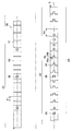
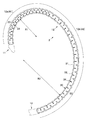
- FIG. 1 is a cross-sectional view taken along line VII-VII.
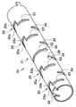
- the perspective view which concerns on a 1st modification and shows the principal part by the side of the base end of a bending tube The perspective view which shows the principal part by the side of the proximal end of a bending tube in connection with a 2nd modification.
- FIG. 1 is a perspective view of an endoscope
- FIG. 2 is a top view of a bending tube
- FIG. 3 is a bottom view of the bending tube
- FIG. 5 is a right side view showing a state where the bending tube is bent upward
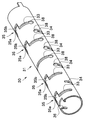
- FIG. 6 is a perspective view showing a main part of the proximal end side of the bending tube.
- An endoscope 1 shown in FIG. 1 is, for example, a nephroscope, and the endoscope 1 is provided at a long insertion portion 2 to be inserted into a subject and a proximal end of the insertion portion 2.
- the operation unit 3 and the eyepiece unit 5 provided at the base end of the operation unit 3 are provided.
- the configuration of the endoscope 1 will be described by taking a so-called fiberscope configuration as an example.
- the endoscope to which the present invention is applied is not limited to the fiberscope. .
- the insertion portion 2 has a distal end hard portion 11 located on the distal end side, a bending portion 12 provided continuously with the proximal end of the distal end hard portion 11, and a flexibility provided continuously with the proximal end of the bending portion 12. And a flexible tube portion 13. Note that an observation lens, an illumination lens, and the like (not shown) are provided in the distal end hard portion 11.
- the bending portion 12 can be bent in two directions, for example, up and down, when the bending lever 14 provided in the operation portion 3 is rotated.
- the operation unit 3 is provided with a treatment instrument insertion port 15.
- the treatment instrument insertion port 15 is inserted into the proximal end side of the treatment instrument insertion channel 16 (see FIG. 7) inserted into the insertion portion 2.
- the treatment instrument inserted into the treatment instrument insertion port 15 is guided to the distal end side of the insertion portion 2 via the treatment instrument insertion channel 16, and from the opening formed on the distal end surface of the distal end rigid portion 11, It is possible to project into the subject.
- the light guide 17 for transmitting the illumination light to the illumination lens described above and the observation lens described above are condensed.
- An image guide 18 for transmitting an optical image in the subject to the eyepiece 5, angle wires 19a, 19b for bending the bending portion 12 in conjunction with the turning operation of the bending lever 14, etc. (FIG. 7). See) is inserted.
- the bending portion 12 includes a first bending portion 12 a located on the distal end side and a second end connected to the base end of the first bending portion 12 a. And a curved portion 12b.
- the first and second curved portions 12a and 12b have different minimum curvature radii when curved, and the minimum curvature radius R1 of the first curved portion 12a is smaller than the minimum curvature radius R2 of the second curved portion 12b. Is also set small (see FIG. 5).
- the bending portion 12 is not limited to one having a configuration in which the minimum radius of curvature at the time of bending is different in two steps on the distal end side and the proximal end side, for example, from the distal end side to the proximal end side. Needless to say, the minimum curvature radius up to this point may be uniform.
- the bending portion 12 is made of, for example, a bending tube 30 mainly composed of a cylindrical bending tube main body 31 made of a superelastic alloy material, and a resin-made covering the periphery of the bending tube 30. And an outer skin 32.
- the superelastic alloy material constituting the bending tube main body 31 include Ni—Ti (nickel titanium), titanium alloy, ⁇ titanium, pure titanium, 64 titanium, A7075, and the like. Is not to be done.
- the bending tube body 31 is provided with a plurality of bending slots whose basic shape is a partially arc-shaped long hole extending in the circumferential direction of the bending tube body 31, for example, by laser processing.
- the bending tube body 31 has a bending direction as a bending slot.
- a plurality of first bending slots 33 extending from the upper side to the lower side and a plurality of second bending slots 34 extending from the lower side in the bending direction of the bending tube main body 31 to the upper side are provided.
- each of the bending slots 33 and 34 is basically constituted by a partially arc-shaped elongated hole having an axially symmetric shape with respect to the longitudinal axis O.
- the first bending slots 33 are arranged in a row as a first arrangement on one side in the circumferential direction of the bending tube main body 31 (upward in the bending direction). These first bending slots 33 are arranged in a row for each preset pitch P1 in the first bending region A1 set on the bending tube body 31 corresponding to the first bending portion 12a, and further, In the second bending region A2 set on the bending tube main body 31 corresponding to the bending portion 12b, the pitches P2 (where P1 ⁇ P2) set in advance are arranged in a line.
- the second bending slots 34 are arranged in a row as a second arrangement on the other side in the circumferential direction of the bending tube main body 31 (lower side in the bending direction). These second bending slots 34 are arranged in a line for each preset pitch P1 in the first bending region A1 set on the bending tube body 31, and the second bending slots 34 are set on the bending tube body 31. In the curved area A2, they are arranged in a line for every preset pitch P2.
- the second bending slot 34 is half pitch (P1) in the longitudinal axis O direction of the bending tube body 31 with respect to the first bending slot 33. / 2) It is arranged in an offset state.
- the second bending slot 34 is arranged in a state offset from the first bending slot 33 by a half pitch (P2 / 2) in the longitudinal axis O direction of the bending tube body 31.
- P2 / 2 half pitch
- the bending tube main body 31 has a torsion suppression region A3 in a region from the base end to a predetermined position on the distal end side (for example, approximately the center of the bending tube main body 31).
- the first and second bending slots 33 and 34 arranged in the torsion suppression region A3 are basically processed in a crank shape in the middle, whereby the first and second bending slots 33 and 34 are processed.
- a twist preventing tab mechanism 35 is formed in the middle of 34.
- the torsion prevention tab mechanism 35 includes a tab 35a projecting in the axial direction of the bending tube body 31, and a pocket 35b recessed to face the tab 35a.
- reference numeral 36 denotes a hole for attaching the wire guide.
- the torsion preventing tab mechanism 35 at the portion where the hole 36 for attaching the wire guide is formed has another problem due to space problems. It is formed in the opposite direction to the torsion prevention tab mechanism 35 of the part.
- the first bending slot 33 is located on the proximal end side of the arrangement and is located on the most proximal end. With respect to at least one of the first bending slots 33 excluding the first bending slot 33, the torsion preventing tab mechanism 35 is removed. In the present embodiment, specifically, among the first bending slots 33 arranged in the torsion suppression region A3, for example, the third first bending slot 33 counted from the most proximal end is cranked halfway. The twist preventing tab mechanism 35 is omitted.
- the second bending slot 34 located on the proximal end side of the arrangement and the most proximal end is provided. With respect to at least one of the second bending slots 34 excluding the two bending slots 34, the torsion prevention tab mechanism 35 is removed.
- the third second bending slot 34 counted from the most proximal end is cranked halfway. The twist preventing tab mechanism 35 is omitted.
- the twist preventing tab mechanism 35 of the third first and second bending slots 33 and 34 counted from the most proximal end is omitted.
- the stress due to the rotational torque is approximately the first and second positions located at the most proximal end and the second end. It became clear that the concentration was concentrated on the bending slots 33 and 34, and in particular, the concentration on the first and second bending slots 33 and 34 located at the most proximal end was remarkable.
- the first and second bending slots 33 and 34 located on the base end side to be twisted. It has also become clear that it is effective to allow the first and second bending slots 33 and 34 located at the third to fourth positions to be twisted. Therefore, in the present embodiment, the first and second first and second bending slots 33 and 34, which are positioned at the most proximal end and the second, most effectively relax the stress concentration of the first and second bending slots 33 and 34.
- the torsion prevention tab mechanism 35 of the second bending slots 33 and 34 is omitted.
- the first and second bending slots in order to further enhance the durability against stress concentration on the first and second bending slots 33 and 34 located at the most proximal end and the second, the first and second bending slots.
- Round holes 38 are provided at the end portions 33 and 34 as stress concentration preventing portions. The diameters of the round holes 38 are set to be larger than the widths of the first and second bending slots 33 and 34, whereby the stress concentrated on the end portions of the slots can be dispersed.
- the bending tube main body 31 is twisted in the middle of the first and second bending slots 33 and 34 located in the region (twisting suppression region A3) from the proximal end to the predetermined position on the distal end side.
- the bending tube 30 for an endoscope which includes a prevention tab mechanism 35 and the bending of the bending tube body 31 is allowed by the first and second bending slots 33 and 34
- the bending tube body 31 is arranged in the same direction along the longitudinal direction.
- the first and second bending slots 33 and 34 respectively arranged in the first and second bending slots 33 and 34
- the first and second bending slots 33 and 34 are located on the base end side of each arrangement (first and second arrangements).
- Torsion about the axis of the bending tube 30 It is possible to improve durability without decreasing more than necessary sex.
- the endoscope 1 of the present embodiment including the bending portion 12 that allows only bending in two directions the bending with respect to the bending portion 12 is performed in order to direct the distal end hard portion 11 in an arbitrary direction within the body cavity.
- the operation and the rotation operation around the axis with respect to the insertion portion 2 are combined, and the durability of the bending tube 30 is improved while maintaining the torsional rigidity around the axis appropriately corresponding to such rotation operation. can do.
- round hole 38 is formed only in the most proximal end and the end portions of the first and second bending slots 33 and 34 located at the second end has been described.
- round holes 38 are also formed at the end portions of the third first and second bending slots 33 and 34 where an increase in stress is expected due to the removal of the twist preventing tab mechanism 35. It is possible to provide.
- first and second bending slots 33 and 34 located in the third among the first and second bending slots 33 and 34 on the twist suppressing region A3 are used for preventing twisting.
- the tab mechanism 35 is removed has been described, depending on the rigidity required for the torsion suppression region A3, the pitch of each slot, and the like, for example, as shown in FIG. It is also possible to remove the twist preventing tab mechanism 35 for the first and second bending slots 33 and 34.
- the first and second bending slots 33 and 34 (for example, the third ones) corresponding to each other as a target for removing the twist preventing tab mechanism 35 are used.
- the first and second bending slots 33 and 34 are set has been described, it is also possible to make the object from which the twist preventing tab mechanism 35 is removed different between the first arrangement and the second arrangement. is there.
- the third and fourth twist prevention tab mechanisms 35 are removed with respect to the first arrangement, and any of the twist prevention tab mechanisms 35 with respect to the second arrangement. Configurations that are not removed are shown. With this configuration, for example, even when the rigidity in each bending direction is different due to the influence of a built-in object inserted into the bending tube 30, durability is ensured while accurately ensuring the torsional rigidity around the axis. Can be improved.
- the stress concentration preventing portion is configured by the round hole 38
- the long side extends along the central axis of the bending tube body 31. It is also possible to configure with an elliptical hole 39. In this case, it is desirable that the long side of each elliptical hole 39 is set wider than the width of each of the first and second bending slots 33 and 34.
- the stress concentration preventing portion can be configured by an elliptical hole 40 having a short side extending along the central axis of the bending tube main body.
- the short side of each elliptical hole 40 is set wider than the width of each of the first and second bending slots 33 and 34.
- the stress concentration preventing portion can be constituted by a hole portion 41 formed of a combination of a plurality of arcs or the like.
- the width of each hole 41 is set wider than the width of each of the first and second bending slots 33 and 34.
Landscapes
- Physics & Mathematics (AREA)
- Health & Medical Sciences (AREA)
- Life Sciences & Earth Sciences (AREA)
- Optics & Photonics (AREA)
- Surgery (AREA)
- General Physics & Mathematics (AREA)
- Astronomy & Astrophysics (AREA)
- Biomedical Technology (AREA)
- Animal Behavior & Ethology (AREA)
- Engineering & Computer Science (AREA)
- Pathology (AREA)
- Heart & Thoracic Surgery (AREA)
- Medical Informatics (AREA)
- Molecular Biology (AREA)
- Radiology & Medical Imaging (AREA)
- General Health & Medical Sciences (AREA)
- Public Health (AREA)
- Veterinary Medicine (AREA)
- Nuclear Medicine, Radiotherapy & Molecular Imaging (AREA)
- Biophysics (AREA)
- Instruments For Viewing The Inside Of Hollow Bodies (AREA)
- Endoscopes (AREA)
Abstract
Description
Claims (7)
- 超弾性合金からなる円筒状の湾曲管本体と、前記湾曲管本体の長手軸方向に沿って設定間隔毎に配列されて前記湾曲管本体の周方向にそれぞれ延在する複数の湾曲用スロットと、前記湾曲管本体の基端から先端側の所定位置までの領域の前記各湾曲用スロットの中途にそれぞれ形成した捩り防止用タブ機構と、を備え、前記湾曲用スロットによって前記湾曲管本体の湾曲を許容する内視鏡用湾曲管において、
前記湾曲管本体の長手方向に沿って同列に配列された前記各湾曲用スロットのうち、当該配列の基端側に位置する前記湾曲用スロットであって、且つ、最基端に位置する前記湾曲用スロットを除く少なくとも何れか1つの前記湾曲用スロットの前記捩り防止用タブ機構を除去したことを特徴とする内視鏡用湾曲管。 - 同列に配列された前記各湾曲用スロットのうち、当該配列の最基端に位置する前記湾曲用スロットから数えて3個目或いは4個目の前記捩り防止用タブ機構の少なくとも何れか1つを除去したことを特徴とする請求項1に記載の内視鏡用湾曲管。
- 前記各湾曲用スロットは、前記湾曲管本体の一方の湾曲方向に沿う第1の配列と、前記湾曲管本体の他方の湾曲方向に沿う第2の配列と、を有し、
前記第1の配列と前記第2の配列とで、前記捩り防止用タブ機構を除去する対象となる前記湾曲用スロットが異なることを特徴とする請求項1に記載の内視鏡用湾曲管。 - 前記捩れ防止用タブ機構を除去した前記湾曲用スロットよりも基端側に位置する前記湾曲用スロットの端部に、応力集中防止部を設けたことを特徴とする請求項1に記載の内視鏡用湾曲管。
- 前記捩れ防止用タブ機構を除去した前記湾曲用スロットの端部に、応力集中防止部を設けたことを特徴とする請求項1に記載の内視鏡用湾曲管。
- 前記応力集中防止部は、前記湾曲用スロットの幅よりも直径が大きい丸孔であることを特徴とする請求項4又は請求項5に記載の内視鏡用湾曲管。
- 前記応力集中防止部は、前記湾曲用スロットの幅よりも幅広な孔部であることを特徴とする請求項4又は請求項5に記載の内視鏡用湾曲管。
Priority Applications (4)
| Application Number | Priority Date | Filing Date | Title |
|---|---|---|---|
| EP14883111.8A EP2997875A4 (en) | 2014-02-18 | 2014-09-30 | Endoscope curved tube |
| JP2015531776A JP5816779B1 (ja) | 2014-02-18 | 2014-09-30 | 内視鏡用湾曲管及び内視鏡 |
| CN201480037683.6A CN105358038B (zh) | 2014-02-18 | 2014-09-30 | 内窥镜用弯曲管 |
| US14/969,553 US9820635B2 (en) | 2014-02-18 | 2015-12-15 | Bending tube for endoscope and endoscope |
Applications Claiming Priority (2)
| Application Number | Priority Date | Filing Date | Title |
|---|---|---|---|
| JP2014028933 | 2014-02-18 | ||
| JP2014-028933 | 2014-02-18 |
Related Child Applications (1)
| Application Number | Title | Priority Date | Filing Date |
|---|---|---|---|
| US14/969,553 Continuation US9820635B2 (en) | 2014-02-18 | 2015-12-15 | Bending tube for endoscope and endoscope |
Publications (1)
| Publication Number | Publication Date |
|---|---|
| WO2015125334A1 true WO2015125334A1 (ja) | 2015-08-27 |
Family
ID=53877864
Family Applications (1)
| Application Number | Title | Priority Date | Filing Date |
|---|---|---|---|
| PCT/JP2014/076086 WO2015125334A1 (ja) | 2014-02-18 | 2014-09-30 | 内視鏡用湾曲管 |
Country Status (5)
| Country | Link |
|---|---|
| US (1) | US9820635B2 (ja) |
| EP (1) | EP2997875A4 (ja) |
| JP (1) | JP5816779B1 (ja) |
| CN (1) | CN105358038B (ja) |
| WO (1) | WO2015125334A1 (ja) |
Cited By (3)
| Publication number | Priority date | Publication date | Assignee | Title |
|---|---|---|---|---|
| US20160310701A1 (en) * | 2013-12-10 | 2016-10-27 | St. Jude Medical, Atrial Fibrillation Division, Inc. | Catheter curve shape strut |
| JP2018183594A (ja) * | 2017-04-26 | 2018-11-22 | バイオセンス・ウエブスター・(イスラエル)・リミテッドBiosense Webster (Israel), Ltd. | 屈折可能な挿入ツールの製造方法 |
| JP2022511153A (ja) * | 2018-02-19 | 2022-01-31 | ベンディット テクノロジーズ リミテッド. | 柔軟性および追従性が改善されたステアリングツール |
Families Citing this family (14)
| Publication number | Priority date | Publication date | Assignee | Title |
|---|---|---|---|---|
| US11730505B2 (en) | 2016-12-16 | 2023-08-22 | The Hospital For Sick Children | Flexible articulate surgical tool |
| DE102017103818A1 (de) * | 2017-02-24 | 2018-08-30 | Hoya Corporation | Endoskop mit einem steuerbaren beweglichen Zwischenabschnitt proximal vom Biegeabschnitt |
| DE102017103819A1 (de) * | 2017-02-24 | 2018-08-30 | Hoya Corporation | Endoskop mit mehreren Biegeabschnitten |
| CN107007241A (zh) * | 2017-03-09 | 2017-08-04 | 上海延顺内窥镜有限公司 | 用于内窥镜头端弯曲部的蛇骨 |
| US11007347B2 (en) * | 2017-04-26 | 2021-05-18 | Biosense Webster (Israel) Ltd. | Deflectable insertion tool |
| CN107802229A (zh) * | 2017-09-21 | 2018-03-16 | 华中科技大学鄂州工业技术研究院 | 一种内窥镜的弯曲管 |
| CN108553070B (zh) * | 2018-05-17 | 2020-09-18 | 黄琴 | 可控弯曲管结构 |
| WO2020094193A1 (de) * | 2018-11-07 | 2020-05-14 | Richard Wolf Gmbh | Endoskopisches instrument |
| CN109497915B (zh) * | 2018-12-25 | 2024-03-22 | 深圳市先赞科技有限公司 | 内窥镜的弯曲部及内窥镜 |
| CN109893073A (zh) * | 2019-04-19 | 2019-06-18 | 广州瑞派医疗器械有限责任公司 | 医用蛇骨管 |
| WO2020232085A1 (en) | 2019-05-15 | 2020-11-19 | Boston Scientific Scimed, Inc. | Medical device having asymmetric bending |
| US11478609B2 (en) * | 2019-09-26 | 2022-10-25 | Biosense Webster (Israel) Ltd. | Bendable guidewire |
| WO2021184151A1 (zh) * | 2020-03-16 | 2021-09-23 | 张敏 | 一种内窥镜蛇骨及内窥镜 |
| CN113273949B (zh) * | 2021-04-01 | 2023-11-10 | 珠海普生医疗科技有限公司 | 一种内窥镜弯曲管及内窥镜 |
Citations (2)
| Publication number | Priority date | Publication date | Assignee | Title |
|---|---|---|---|---|
| JP2009537280A (ja) * | 2006-05-19 | 2009-10-29 | コンメッド エンドスコーピック テクノロジーズ インコーポレーテッド | 可動医療器具 |
| JP2013545553A (ja) * | 2010-12-02 | 2013-12-26 | ジャイラス・エーシーエムアイ・インコーポレーテッド | 内視鏡シャフト |
Family Cites Families (10)
| Publication number | Priority date | Publication date | Assignee | Title |
|---|---|---|---|---|
| US6860849B2 (en) * | 2000-05-08 | 2005-03-01 | Pentax Corporation | Flexible tube for an endoscope |
| JP3776767B2 (ja) * | 2000-10-02 | 2006-05-17 | オリンパス株式会社 | 内視鏡 |
| JP2003061902A (ja) * | 2001-08-23 | 2003-03-04 | Pentax Corp | 可撓性可変内視鏡 |
| JP5165946B2 (ja) * | 2007-07-12 | 2013-03-21 | オリンパス株式会社 | 内視鏡装置 |
| JP2009089724A (ja) * | 2007-10-03 | 2009-04-30 | Olympus Corp | 分離型内視鏡 |
| US20100312056A1 (en) | 2009-06-03 | 2010-12-09 | Gyrus, ACMI, Inc. | Endoscope shaft |
| US20110112365A1 (en) * | 2009-06-03 | 2011-05-12 | Gyrus Acmi, Inc. | Endoscope shaft |
| EP2436299B1 (en) * | 2010-07-29 | 2013-09-11 | Olympus Medical Systems Corp. | Bending mechanism |
| JP5734786B2 (ja) * | 2011-08-10 | 2015-06-17 | オリンパス株式会社 | 内視鏡 |
| US8967204B2 (en) * | 2012-08-24 | 2015-03-03 | Olympus Medical Systems Corporation | Curved pipe for endoscopes |
-
2014
- 2014-09-30 CN CN201480037683.6A patent/CN105358038B/zh active Active
- 2014-09-30 JP JP2015531776A patent/JP5816779B1/ja active Active
- 2014-09-30 EP EP14883111.8A patent/EP2997875A4/en not_active Withdrawn
- 2014-09-30 WO PCT/JP2014/076086 patent/WO2015125334A1/ja active Application Filing
-
2015
- 2015-12-15 US US14/969,553 patent/US9820635B2/en active Active
Patent Citations (2)
| Publication number | Priority date | Publication date | Assignee | Title |
|---|---|---|---|---|
| JP2009537280A (ja) * | 2006-05-19 | 2009-10-29 | コンメッド エンドスコーピック テクノロジーズ インコーポレーテッド | 可動医療器具 |
| JP2013545553A (ja) * | 2010-12-02 | 2013-12-26 | ジャイラス・エーシーエムアイ・インコーポレーテッド | 内視鏡シャフト |
Non-Patent Citations (1)
| Title |
|---|
| See also references of EP2997875A4 * |
Cited By (5)
| Publication number | Priority date | Publication date | Assignee | Title |
|---|---|---|---|---|
| US20160310701A1 (en) * | 2013-12-10 | 2016-10-27 | St. Jude Medical, Atrial Fibrillation Division, Inc. | Catheter curve shape strut |
| US11116941B2 (en) * | 2013-12-10 | 2021-09-14 | St. Jude Medical, Atrial Fibrillation Division, Inc. | Catheter curve shape strut |
| JP2018183594A (ja) * | 2017-04-26 | 2018-11-22 | バイオセンス・ウエブスター・(イスラエル)・リミテッドBiosense Webster (Israel), Ltd. | 屈折可能な挿入ツールの製造方法 |
| JP7106337B2 (ja) | 2017-04-26 | 2022-07-26 | バイオセンス・ウエブスター・(イスラエル)・リミテッド | 屈折可能な挿入ツールの製造方法 |
| JP2022511153A (ja) * | 2018-02-19 | 2022-01-31 | ベンディット テクノロジーズ リミテッド. | 柔軟性および追従性が改善されたステアリングツール |
Also Published As
| Publication number | Publication date |
|---|---|
| EP2997875A1 (en) | 2016-03-23 |
| EP2997875A4 (en) | 2017-03-01 |
| US20160100745A1 (en) | 2016-04-14 |
| JPWO2015125334A1 (ja) | 2017-03-30 |
| US9820635B2 (en) | 2017-11-21 |
| CN105358038A (zh) | 2016-02-24 |
| JP5816779B1 (ja) | 2015-11-18 |
| CN105358038B (zh) | 2017-07-04 |
Similar Documents
| Publication | Publication Date | Title |
|---|---|---|
| JP5816779B1 (ja) | 内視鏡用湾曲管及び内視鏡 | |
| JP5537748B1 (ja) | 内視鏡用湾曲管 | |
| JP5981080B1 (ja) | 内視鏡用湾曲管及びこの内視鏡用湾曲管を具備した内視鏡 | |
| JP5932151B2 (ja) | 副鼻腔内視鏡 | |
| JP5444516B1 (ja) | 湾曲管、医療機器 | |
| ES2379767T3 (es) | Alambre guía médico | |
| JP5711434B1 (ja) | 内視鏡 | |
| US20170224192A1 (en) | Endoscope bending portion | |
| US20100331618A1 (en) | Endoscope shaft frame member with wavy slot | |
| WO2016047265A1 (ja) | 内視鏡用湾曲管及びこの内視鏡用湾曲管を具備した内視鏡 | |
| JP5897237B1 (ja) | 内視鏡 | |
| KR102018860B1 (ko) | 방향조절와이어 고정기능이 강화된 연성 카테터 | |
| JP6422623B1 (ja) | 内視鏡の湾曲部 | |
| EP3202301A1 (en) | Bendable tube segment, bendable tube, and insertion device | |
| JP6697291B2 (ja) | 内視鏡湾曲管 | |
| JP6257854B2 (ja) | 内視鏡 | |
| JP4715378B2 (ja) | 内視鏡の挿入部 | |
| JP6157433B2 (ja) | 内視鏡及び内視鏡システム | |
| WO2016056416A1 (ja) | 内視鏡 | |
| JP2021126228A (ja) | コイルシースおよび医療デバイス | |
| JP2009261523A (ja) | 内視鏡 | |
| JP2006271491A (ja) | 内視鏡の処置具挿通チャンネル | |
| JP2010063628A (ja) | 内視鏡 |
Legal Events
| Date | Code | Title | Description |
|---|---|---|---|
| WWE | Wipo information: entry into national phase |
Ref document number: 201480037683.6 Country of ref document: CN |
|
| ENP | Entry into the national phase |
Ref document number: 2015531776 Country of ref document: JP Kind code of ref document: A |
|
| 121 | Ep: the epo has been informed by wipo that ep was designated in this application |
Ref document number: 14883111 Country of ref document: EP Kind code of ref document: A1 |
|
| WWE | Wipo information: entry into national phase |
Ref document number: 2014883111 Country of ref document: EP |
|
| NENP | Non-entry into the national phase |
Ref country code: DE |