WO2015125326A1 - 内燃機関の制御装置及び制御方法 - Google Patents
内燃機関の制御装置及び制御方法 Download PDFInfo
- Publication number
- WO2015125326A1 WO2015125326A1 PCT/JP2014/074445 JP2014074445W WO2015125326A1 WO 2015125326 A1 WO2015125326 A1 WO 2015125326A1 JP 2014074445 W JP2014074445 W JP 2014074445W WO 2015125326 A1 WO2015125326 A1 WO 2015125326A1
- Authority
- WO
- WIPO (PCT)
- Prior art keywords
- fuel
- internal combustion
- combustion engine
- fuel injection
- stopped
- Prior art date
- Legal status (The legal status is an assumption and is not a legal conclusion. Google has not performed a legal analysis and makes no representation as to the accuracy of the status listed.)
- Ceased
Links
Images

Classifications
-
- F—MECHANICAL ENGINEERING; LIGHTING; HEATING; WEAPONS; BLASTING
- F02—COMBUSTION ENGINES; HOT-GAS OR COMBUSTION-PRODUCT ENGINE PLANTS
- F02D—CONTROLLING COMBUSTION ENGINES
- F02D41/00—Electrical control of supply of combustible mixture or its constituents
- F02D41/30—Controlling fuel injection
- F02D41/3082—Control of electrical fuel pumps
-
- F—MECHANICAL ENGINEERING; LIGHTING; HEATING; WEAPONS; BLASTING
- F02—COMBUSTION ENGINES; HOT-GAS OR COMBUSTION-PRODUCT ENGINE PLANTS
- F02D—CONTROLLING COMBUSTION ENGINES
- F02D41/00—Electrical control of supply of combustible mixture or its constituents
- F02D41/02—Circuit arrangements for generating control signals
- F02D41/04—Introducing corrections for particular operating conditions
- F02D41/042—Introducing corrections for particular operating conditions for stopping the engine
-
- F—MECHANICAL ENGINEERING; LIGHTING; HEATING; WEAPONS; BLASTING
- F02—COMBUSTION ENGINES; HOT-GAS OR COMBUSTION-PRODUCT ENGINE PLANTS
- F02D—CONTROLLING COMBUSTION ENGINES
- F02D41/00—Electrical control of supply of combustible mixture or its constituents
- F02D41/02—Circuit arrangements for generating control signals
- F02D41/04—Introducing corrections for particular operating conditions
- F02D41/06—Introducing corrections for particular operating conditions for engine starting or warming up
- F02D41/062—Introducing corrections for particular operating conditions for engine starting or warming up for starting
- F02D41/065—Introducing corrections for particular operating conditions for engine starting or warming up for starting at hot start or restart
-
- F—MECHANICAL ENGINEERING; LIGHTING; HEATING; WEAPONS; BLASTING
- F02—COMBUSTION ENGINES; HOT-GAS OR COMBUSTION-PRODUCT ENGINE PLANTS
- F02D—CONTROLLING COMBUSTION ENGINES
- F02D41/00—Electrical control of supply of combustible mixture or its constituents
- F02D41/30—Controlling fuel injection
- F02D41/32—Controlling fuel injection of the low pressure type
- F02D41/34—Controlling fuel injection of the low pressure type with means for controlling injection timing or duration
-
- F—MECHANICAL ENGINEERING; LIGHTING; HEATING; WEAPONS; BLASTING
- F02—COMBUSTION ENGINES; HOT-GAS OR COMBUSTION-PRODUCT ENGINE PLANTS
- F02D—CONTROLLING COMBUSTION ENGINES
- F02D2200/00—Input parameters for engine control
- F02D2200/02—Input parameters for engine control the parameters being related to the engine
- F02D2200/06—Fuel or fuel supply system parameters
- F02D2200/0606—Fuel temperature
-
- F—MECHANICAL ENGINEERING; LIGHTING; HEATING; WEAPONS; BLASTING
- F02—COMBUSTION ENGINES; HOT-GAS OR COMBUSTION-PRODUCT ENGINE PLANTS
- F02D—CONTROLLING COMBUSTION ENGINES
- F02D2250/00—Engine control related to specific problems or objectives
- F02D2250/02—Fuel evaporation in fuel rails, e.g. in common rails
-
- Y—GENERAL TAGGING OF NEW TECHNOLOGICAL DEVELOPMENTS; GENERAL TAGGING OF CROSS-SECTIONAL TECHNOLOGIES SPANNING OVER SEVERAL SECTIONS OF THE IPC; TECHNICAL SUBJECTS COVERED BY FORMER USPC CROSS-REFERENCE ART COLLECTIONS [XRACs] AND DIGESTS
- Y02—TECHNOLOGIES OR APPLICATIONS FOR MITIGATION OR ADAPTATION AGAINST CLIMATE CHANGE
- Y02T—CLIMATE CHANGE MITIGATION TECHNOLOGIES RELATED TO TRANSPORTATION
- Y02T10/00—Road transport of goods or passengers
- Y02T10/10—Internal combustion engine [ICE] based vehicles
- Y02T10/40—Engine management systems
Definitions
- the present invention relates to a control device and a control method for an internal combustion engine including a fuel injection valve and an electric fuel pump that pumps fuel to the fuel injection valve.
- Patent Document 1 the fuel pressure of the high-pressure delivery pipe and the low-pressure delivery pipe is reduced by opening the electromagnetic relief valve and stopping the operation of the low-pressure fuel pump at the end of the operation of the vehicle.
- a vehicle control device is disclosed that prevents the exhaust properties from deteriorating at the next start.
- an electromagnetic relief valve is provided, and the operation of this electromagnetic relief valve reduces the fuel pressure in the fuel pipe. There was a problem that the cost was increased by the addition.
- the present invention has been made in view of the above-described problems, and provides a control device and a control method for an internal combustion engine that can suppress fuel leakage from the fuel injection valve during an operation stop period of the internal combustion engine with a simple configuration.
- the purpose is to do.
- An internal combustion engine control method is a control method for an internal combustion engine comprising a fuel injection valve and an electric fuel pump that pumps fuel to the fuel injection valve, and includes the following steps. When the operation of the internal combustion engine is stopped, the drive of the fuel pump is stopped, and after the drive of the fuel pump is stopped, the fuel injection by the fuel injection valve is stopped.
- the fuel pressure in the fuel pipe is reduced by the fuel injection by the fuel injection valve in a state where the drive of the fuel pump is stopped and the fuel pipe is not replenished. Without using a device for reducing the fuel pressure, it is possible to suppress fuel leakage from the fuel injection valve during the operation stop period.
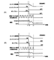
- FIG. 1 is a system configuration diagram of an internal combustion engine in an embodiment of the present invention. It is a flowchart which shows the process at the time of the stop of the internal combustion engine in embodiment of this invention. It is a diagram which shows the correlation with the fuel temperature and the target fuel pressure PFTG during a stop in embodiment of this invention. It is a time chart for demonstrating the process characteristic at the time of the stop of the internal combustion engine in embodiment of this invention, (A) is a characteristic at the time of low temperature, (B) is a time chart which shows the characteristic at the time of high temperature. It is a flowchart which shows the process at the time of the stop of the internal combustion engine in embodiment of this invention.
- (A) is a characteristic at the time of low temperature
- (B) is a time chart which shows the characteristic at the time of high temperature. It is a flowchart which shows the process at the time of the stop of the internal combustion engine in embodiment of this invention.
- FIG. 1 shows an example of an internal combustion engine to which a control device and a control method according to the present invention are applied.
- the internal combustion engine 1 is an engine mounted on a vehicle as a power source, and includes a fuel injection valve 3 in an intake pipe 2 upstream of the intake valve 4 of each cylinder.
- the fuel injection valve 3 is controlled so as to intermittently inject fuel into the intake pipe 2 in accordance with the injection timing of each cylinder.
- the fuel injected by the fuel injection valve 3 into the intake pipe 2 is sucked into the combustion chamber 5 through the intake valve 4 together with air to form an air-fuel mixture.
- the air-fuel mixture in the combustion chamber 5 is ignited and burned by spark ignition by the spark plug 6.
- the combustion gas in the combustion chamber 5 is discharged to the exhaust pipe 8 through the exhaust valve 7.
- the electronic control throttle 10 adjusts the intake air amount of the internal combustion engine 1 by changing the opening degree by the throttle motor 9.
- the electronic control throttle 10 is provided in an intake duct common to each cylinder on the upstream side of a portion where the fuel injection valve 3 of the intake pipe 2 is provided.
- the fuel supply device 13 is a device that pumps the fuel in the fuel tank 11 to the fuel injection valve 3 by the fuel pump 12.
- the fuel supply device 13 includes a fuel tank 11, a fuel pump 12, a pressure adjustment valve 14, an orifice 15, a fuel gallery pipe 16, a fuel supply pipe 17, a fuel return pipe 18, a jet pump 19, and a fuel transfer pipe 20.
- the fuel pump 12 is an electric pump and is provided in the fuel tank 11. Further, the fuel pump 12 opens when the discharge pressure of the fuel pump 12 exceeds the upper limit pressure, and the fuel discharged from the fuel pump 12 is supplied to the fuel tank. 11 has a relief valve 12b for relief.
- the check valve 12a and the relief valve 12b are mechanical valves that displace the valve body between a valve opening position and a valve closing position by using a differential pressure across the valve.
- the fuel supply pipe 17 is a pipe connecting the fuel pump 12 and the fuel gallery pipe 16, one end of the fuel supply pipe 17 is connected to the discharge port of the fuel pump 12, and the fuel gallery pipe is connected to the other end of the fuel supply pipe 17. 16 is connected.
- the fuel supply port of the fuel injection valve 3 of each cylinder is connected to the fuel gallery pipe 16, and the fuel is distributed to the fuel injection valve 3 of each cylinder via the fuel gallery pipe 16.
- the fuel return pipe 18 extends from the fuel supply pipe 17 in the fuel tank 11, and the end of the fuel return pipe 18 opens into the fuel tank 11.
- the fuel return pipe 18 is provided with a pressure regulating valve 14, an orifice 15, and a jet pump 19 in order from the upstream side.
- the pressure regulating valve 14 is a mechanical type including a valve body 14a that opens and closes the fuel return pipe 18 and an elastic member 14b such as a coil spring that presses the valve body 14a toward the valve seat on the upstream side of the fuel return pipe 18. It is a valve.
- the pressure adjustment valve 14 opens when the fuel pressure in the fuel supply pipe 17 and the fuel gallery pipe 16, in other words, the fuel pressure supplied to the fuel injection valve 3 exceeds the set pressure. Is closed when the pressure is equal to or lower than the set pressure, thereby adjusting the amount of fuel relief so that the fuel pressure in the fuel pipe does not fall below the set pressure.
- the jet pump 19 transfers fuel by the flow of fuel returned into the fuel tank 11 through the pressure regulating valve 14 and the orifice 15.
- the fuel tank 11 is a vertical fuel tank in which a part of the bottom surface is raised and the bottom space is divided into two regions 11a and 11b. Since the suction port of the fuel pump 12 opens into the region 11a, the fuel in the region 11b remains unless the fuel in the region 11b is transferred to the region 11a side. Therefore, the jet pump 19 applies a negative pressure to the fuel transfer pipe 20 by the flow of fuel returned into the region 11a of the fuel tank 11 via the pressure regulating valve 14 and the orifice 15, and the fuel transfer pipe 20 is opened. The fuel in the region 11b to be conducted is guided to the jet pump 19 through the fuel transfer pipe 20, and is discharged into the region 11a together with the return fuel. That is, surplus fuel is discharged from the fuel pump 12 and the fuel is transferred into the fuel tank 11 using the surplus fuel returned to the fuel tank 11.
- the jet pump 19 is provided as described above. However, when the shape of the fuel tank 11 is not vertical, that is, the bottom space of the fuel tank 11 is not separated, and the suction port of the fuel pump 12 is provided. When the fuel in the fuel tank 11 can be sucked without remaining, the jet pump 19 and the fuel transfer pipe 20 can be omitted.
- An engine control module (ECM) 31 including a microcomputer is a control device that outputs an injection pulse signal for controlling the injection operation by the fuel injection valve 3.
- the ECM 31 further includes an ignition timing and electronic control by the spark plug 6. It has a function of controlling the opening degree of the throttle 10 and the like.
- a fuel pump control module (FPCM) 30 including a microcomputer outputs a drive signal for the fuel pump 12 to control the fuel pump 12.
- the ECM 31 and the FPCM 30 constituting the control device of the internal combustion engine 1 are configured to be able to communicate with each other, and the ECM 31 transmits a signal indicating a duty ratio in the PWM control of the fuel pump 12 to the FPCM 30. Further, the FPCM 30 transmits a signal indicating the result of failure diagnosis for the fuel pump 12 and the drive circuit of the fuel pump 12 to the ECM 31.
- the ECM 31 receives signals output from various sensors that detect the operating state of the internal combustion engine 1.
- a fuel pressure sensor 33 for detecting the fuel pressure FUPR in the fuel gallery pipe 16, an accelerator pedal depression amount (not shown), in other words, an accelerator opening sensor 34 for detecting the accelerator opening ACC, and the internal combustion engine 1
- An air flow sensor 35 for detecting the intake air flow rate QA, a rotation sensor 36 for detecting the rotational speed NE of the internal combustion engine 1, a water temperature sensor 37 for detecting the cooling water temperature TW of the internal combustion engine 1, and the internal combustion engine 1 based on the oxygen concentration in the exhaust gas.
- a fuel temperature sensor 41 for detecting the temperature TF of the fuel is provided.
- the ECM 31 also receives an output signal from the atmospheric pressure sensor 42 that detects the atmospheric pressure AP, an on / off signal from the ignition switch 43 that commands operation / stop of the internal combustion engine 1, and the like.
- the ECM 31 calculates the ignition timing based on the engine operating conditions such as the engine load and the engine speed NE, and controls energization to the ignition coil (not shown) so that spark discharge is performed by the spark plug 6 at the ignition timing. To do.
- the ECM 31 calculates the target opening of the electronic control throttle 10 from engine operating conditions such as the accelerator opening ACC, and controls the throttle motor 9 so that the opening of the electronic control throttle 10 approaches the target opening. Further, the ECM 31 determines a duty ratio [%] in the PWM control of the fuel pump 12 and transmits a pulse signal indicating the duty ratio to the FPCM 30 as a drive instruction signal for the fuel pump 12.
- the ECM 31 performs PWM of the fuel pump 12 according to the fuel pressure FUPR detected by the fuel pressure sensor 33 and the target fuel pressure set based on the operating conditions of the internal combustion engine 1 (target fuel pressure ⁇ set pressure of the pressure adjusting valve 14).
- the duty ratio in the control can be determined.
- the ECM 31 sets the target fuel pressure to a value that satisfies the relationship “target fuel pressure ⁇ the set pressure of the pressure regulating valve 14”.
- the fuel pressure in the fuel pipe can be maintained in the vicinity of the set pressure of the pressure regulating valve 14.
- the ECM 31 has an excessive amount of fuel that is relieved through the pressure regulating valve 14.
- the duty ratio in the PWM control of the fuel pump 12 can be determined according to the engine operating conditions such as the engine load and the engine speed so that the pump 12 does not perform useless work, and the duty ratio is set as a fixed value. It can also be set as the structure to give.
- the FPCM 30 performs PWM control of energization to the motor of the fuel pump 12 based on the duty ratio instructed from the ECM 31 side.
- the ECM 31 includes a circuit and a control function that the FPCM 30 includes, so that a control device in which the ECM 31 and the FPCM 30 are integrated can be obtained.
- the ECM 31 sets the injection pulse width TI [ms] of the injection pulse signal that controls the valve opening period of the fuel injection valve 3, the intake air flow rate QA, the engine rotational speed NE, the coolant temperature TW, the air-fuel ratio AFR, and the fuel pressure FUPR. Calculate based on the engine operating conditions.
- the ECM 31 detects the fuel injection timing of each cylinder, the ECM 31 outputs an injection pulse signal having an injection pulse width TI to the fuel injection valve 3 of the cylinder that has reached the fuel injection timing.
- the injection amount and the injection timing are controlled.
- the fuel injection valve 3 opens for a period corresponding to the injection pulse width TI, and injects an amount of fuel proportional to the valve opening period [ms].
- the ECM 31 is a fuel pipe between the fuel pump 12 and the fuel injection valve 3 when the internal combustion engine 1 is stopped in order to suppress fuel leakage from the fuel injection valve 3 during the stop period of the internal combustion engine 1.
- a process for reducing the internal fuel pressure below the set pressure of the pressure regulating valve 14 is executed.
- the above-described process for reducing the fuel pressure is also referred to as a fuel pressure reduction process below. That is, when the fuel injection of the fuel injection valve 3 is stopped and the drive of the fuel pump 12 is stopped based on the stop command of the internal combustion engine 1, the fuel pressure in the fuel pipe is held at the set pressure of the pressure adjustment valve 14. However, if the fuel pressure in the fuel pipe can be reduced below the set pressure, the fuel leakage from the fuel injection valve 3 during the stop period can be reduced, so that the internal combustion engine 1 can be started next time.
- the exhaust properties when starting can be improved.
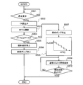
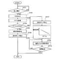
- the flowchart of FIG. 2 shows an example of the fuel pressure lowering process by the ECM 31.
- the ECM 31 is configured to receive power supply even when the ignition switch 43 is switched from on to off, and to shut off the power supply itself after completing a predetermined process when stopping the internal combustion engine 1.
- step S501 the ECM 31 determines whether a stop request for the internal combustion engine 1 has been generated.
- the ECM 31 can determine the occurrence of a stop request for the internal combustion engine 1 when the ignition switch 43 is switched from on to off.
- the stop request for the internal combustion engine 1 by the idle reduction function is a stop request in step S501.
- Shall not be included This is because in the temporary stop process of the internal combustion engine 1 by the idle reduction function, the stop period of the internal combustion engine 1 is short, and fuel leakage from the fuel injection valve 3 is sufficiently small during that period. This is because it is preferable to suppress a decrease in fuel pressure in order to restart the engine.
- step S501 When there is no request to stop the internal combustion engine 1 and the internal combustion engine 1 is continuously operated, the fuel pressure lowering process is unnecessary, and thus the ECM 31 repeats the determination process of step S501 without proceeding to the processes after step S502. On the other hand, when the ECM 31 determines that a request to stop the internal combustion engine 1 is generated, the ECM 31 proceeds to step S502 and reads the fuel temperature TF.
- the ECM 31 can detect the fuel temperature TF based on the output signal of the fuel temperature sensor 41 and can estimate the fuel temperature TF from the operating conditions of the internal combustion engine 1.
- the ECM 31 can estimate the fuel temperature TF from the cooling water temperature TW, the oil temperature TO, the engine load before the stop, and the like, and further, the estimated value of the fuel temperature TF based on the cooling water temperature TW or the like is used as the intake air temperature TIA. Correction can be made based on outside air temperature, atmospheric pressure, and the like.
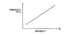
- the ECM 31 When the ECM 31 reads the fuel temperature TF in step S502, the ECM 31 then proceeds to step S503, and calculates the target value PFTG of the fuel pressure during the stop period of the internal combustion engine 1. As shown in FIG. 3, the ECM 31 sets the target fuel pressure PFTG to a higher pressure as the fuel temperature TF read in step S502 is higher. In other words, the fuel pressure lowering margin from the set pressure of the pressure regulating valve 14 is decreased as the fuel temperature TF is higher, and is increased as the fuel temperature TF is lower.
- the ECM 31 reduces the fuel pressure reduction as the fuel temperature TF increases, thereby reducing the fuel pressure during the stop period and reducing the amount of fuel leakage while suppressing the generation of fuel vapor. .
- the ECM 31 sets the target fuel pressure PFTG that is stopped in step S503 that is stopped in step S503
- the ECM 31 proceeds to step S504, and determines whether or not the target fuel pressure PFTG set in step S503 is equal to or higher than the pre-stored heat-resistant fuel pressure PFHOT.
- the heat-resistant fuel pressure PFHOT is a threshold value to be compared with the target fuel pressure PFTG in order to determine whether or not to perform the fuel pressure reduction process.
- a state in which a target fuel pressure PFTG higher than the heat resistant fuel pressure PFHOT is required is that the fuel pressure is lowered below the set pressure of the pressure regulating valve 14 so that the starting failure is caused by the generation of fuel vapor at the time of starting under the heat resistant condition. While the target fuel pressure PFTG lower than the heat resistant fuel pressure PFHOT is required while the fuel pressure may be lower than the set pressure of the pressure regulating valve 14, the state may occur, This is a state in which the generation of fuel vapor is suppressed and stable startability is obtained, and the heat-resistant fuel pressure PFHOT is set in advance so that such a condition can be determined.
- the ECM 31 determines that the target fuel pressure PFTG is equal to or higher than the heat-resistant fuel pressure PFHOT, the ECM 31 proceeds to step S505, and first stops fuel injection by the fuel injection valve 3 based on a stop command for the internal combustion engine 1. Next, the ECM 31 proceeds to step S506, and delays the stop of fuel injection of the fuel injection valve 3 to stop driving of the fuel pump 12, that is, power supply to the fuel pump 12, and stop the internal combustion engine 1. The processing of the fuel supply system is terminated.
- the drive stop of the fuel pump 12 is implemented by, for example, controlling off a power supply relay that cuts off the power supply to the drive circuit of the pump motor.
- the timing at which the drive of the fuel pump 12 is stopped after the fuel injection is stopped can be, for example, a predetermined time after the timing at which the fuel injection is stopped or the timing at which the rotation of the internal combustion engine 1 is stopped.
- step S504 determines in step S504 that the target fuel pressure PFTG is lower than the heat resistant fuel pressure PFHOT
- the ECM 31 proceeds to step S507 and stops driving the fuel pump 12 prior to stopping fuel injection by the fuel injection valve 3.
- the drive of the fuel pump 12 is stopped, for example, by turning off a power relay provided in a power supply line that supplies power to the fuel pump 12.
- the drive of the fuel pump 12 can also be stopped by reducing the on-duty in the PWM control of the fuel pump 12 to a predetermined value.
- the ECM 31 since the ECM 31 stops the fuel injection by the fuel injection valve 3 after stopping the driving of the fuel pump 12 in step S507, the ECM 31 uses the fuel injection valve 3 while the driving of the fuel pump 12 is stopped.
- a period in which fuel injection is performed that is, a period in which fuel is taken away from the fuel pipe in a state where fuel is not replenished in the fuel pipe occurs.
- the fuel pressure in the fuel pipe decreases, and the fuel pressure decreases further as the total amount of fuel injected from the fuel injection valve 3 increases while the drive of the fuel pump 12 is stopped.
- the total amount of fuel injected from the fuel injection valve 3 while the drive of the fuel pump 12 is stopped varies depending on the number of injections, the amount of injection per time, the duration of fuel injection, and the like.
- the ECM 31 proceeds to step S508, and sets the target number of injections INJCNT of the fuel injection valve 3 after the drive of the fuel pump 12 is stopped according to the target fuel pressure PFTG.
- the target injection number INJCNT is a target value of the cumulative number of fuel injections after the drive of the fuel pump 12 is stopped.
- the lower the target fuel pressure PFTG is, the larger the pressure reduction margin from the set pressure of the pressure regulating valve 14 is, and the fuel pressure is the fuel injection in the state where the drive of the fuel pump 12 is stopped. It will decrease as the number of integration increases.
- the ECM 31 sets the target injection number INJCNT to a larger value as the target fuel pressure PFTG is lower. That is, the target injection number INJCNT is the cumulative number of fuel injections required to reduce the fuel pressure to the target fuel pressure PFTG, and the target fuel pressure PFTG is set to a lower pressure as the fuel temperature is lower. Therefore, the target injection number INJCNT is set to a larger number as the fuel temperature is lower.
- step S509 When the ECM 31 sets the target number of injections INJCNT in step S508, the ECM 31 proceeds to step S509 and performs fuel injection by the fuel injection valve 3.
- the ECM 31 sets the injection pulse width TI that defines the fuel injection amount per time, the intake air flow rate QA, the engine rotational speed NE, and the like, as in the operation of the internal combustion engine 1. Calculate based on engine operating conditions. Then, the fuel injected from the fuel injection valve 3 by the fuel injection control in step S509 is ignited and combusted in the combustion chamber of each cylinder by the spark ignition performed by the ignition control that is continued even after the engine stop command.
- step S510 determines whether or not the cumulative number of fuel injections after stopping the driving of the fuel pump 12 has reached the target number of injections INJCNT.
- the cumulative number of fuel injections after the drive of the fuel pump 12 is stopped is smaller than the target injection number INJCNT, in other words, the actual fuel pressure is set to the target fuel pressure PFTG (PFTG ⁇ pressure adjustment valve 14 setting). If it is estimated that the pressure has not decreased to (pressure), the ECM 31 returns to the process of step S509 to continue the fuel injection.
- the ECM 31 estimates that the fuel pressure in the fuel pipe has decreased to the target fuel pressure PFTG, The process of the fuel supply system when the internal combustion engine 1 is stopped by stopping the fuel injection, that is, the fuel pressure lowering process is ended.
- the fuel pressure in the fuel pipe is reduced below the set pressure of the pressure adjusting valve 14, it is compared with the case where the set pressure of the pressure adjusting valve 14 is maintained.
- the fuel leakage from the fuel injection valve 3 during the stop period of the internal combustion engine 1 can be suppressed. If the amount of fuel leakage during the stop period can be suppressed to a low level, the exhaust property can be improved by reducing the amount of unburned fuel when the internal combustion engine 1 is started next time.
- the amount of fuel leakage can be suppressed to a low level by reducing the fuel pressure, the oil tightness required for the fuel injection valve 3 can be reduced compared to the case where the pressure adjustment valve 14 is maintained at the set pressure, and the fuel injection valve The manufacturing cost of 3 can be reduced.
- an electronic control device such as an electromagnetic relief valve is not used to reduce the fuel pressure in the fuel pipe, the fuel pressure in the fuel pipe can be reduced without increasing the system cost. It is possible to omit the process of variably setting the fuel pressure reduction margin according to the fuel temperature when the internal combustion engine 1 is stopped, and to set the uniform target fuel pressure PFTG.
- the fuel pressure sensor 33 detects a pressure drop due to fuel injection after the drive of the fuel pump 12 is stopped, but the fuel after the drive of the fuel pump 12 is stopped.
- the fuel pressure fluctuation due to the injection is large, and when it is configured to stop the fuel injection by judging the arrival at the target fuel pressure PFTG based on the output of the fuel pressure sensor 33, the timing of ending the fuel injection greatly varies, and the fuel leakage It is difficult to stably obtain the effect of reducing the amount.
- the fuel pressure lowering margin is controlled by the cumulative number of fuel injections, the correlation between the cumulative number of fuel injections and the reached fuel pressure is obtained in advance, so that the timing for terminating the fuel injection can be determined. It is stable and the effect of reducing the amount of fuel leakage can be obtained stably.
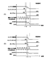
- FIG. 4A and 4B exemplify changes in engine speed, ignition switch, pump power relay, injection pulse signal, and fuel pressure when the ECM 31 performs the processing shown in the flowchart of FIG.
- FIG. 4A shows an example of characteristics when the fuel temperature is lower than that of FIG. 4B
- FIG. 4B shows the case where the fuel temperature is higher than that of FIG.
- An example of characteristics is shown. 4A and 4B, when the ignition switch is switched from on to off at time t1 and a stop command for the internal combustion engine 1 is generated, the pump power supply relay is switched from on to off at time t2. The output of the injection pulse signal is stopped at time t3 with a delay, and the fuel injection by the fuel injection valve 3 is stopped.
- the ECM 31 sets the target fuel pressure PFTG that is stopped according to the fuel temperature, and sets the number of injections after the pump is stopped according to the set target fuel pressure PFTG.
- the fuel pressure can be further reduced. Therefore, instead of changing the number of injections after stopping the pump according to the target fuel pressure PFTG, changing the injection amount per injection in the injection after stopping the pump according to the target fuel pressure PFTG also allows the fuel pressure to be changed. The reduction allowance can be controlled.
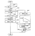
- the flowchart in FIG. 5 exemplifies a fuel pressure reduction process in which the injection amount per injection in the injection after the pump is stopped is changed according to the target fuel pressure PFTG.
- the processing contents of the ECM 31 from step S601 to step S607 are the same as the processing contents of step S501 to step S507 in the flowchart of FIG. 2, and the processing contents of the ECM 31 after step S608 are the same as those in FIG. It differs from the processing content after step S508 in the flowchart.
- step S608 the ECM 31 increases the amount of fuel injected by the fuel injection valve 3 in one injection operation in the stopped state of the fuel pump 12 as the target fuel pressure PFTG being stopped is lower.
- the pulse width of the injection pulse signal in the stopped state is set longer as the target fuel pressure PFTG is lower.
- the fuel injection when the fuel pump 12 is stopped is increased by increasing the injection amount per time. As the total amount of fuel increases, the fuel pressure decreases.
- the correlation between the target fuel pressure PFTG and the injection pulse width in step S608 indicates that the fuel pressure is reduced from the fuel pressure before stopping the engine to the target fuel pressure PFTG that is stopped when the cumulative number of fuel injections is a constant value. It is pre-adapted so that it can be made.
- the injection pulse width that is variably set according to the target fuel pressure PFTG is set to a value within a range where ignition and combustion can be performed by spark ignition by the spark plug.
- step S609 sets the injection pulse width set in step S608 as a value used for injection control of the fuel injection valve 3. Then, the ECM 31 proceeds to step S610, and determines whether or not the cumulative number of fuel injections after stopping the driving of the fuel pump 12 has reached the target injection number INJCNT, which is a fixed value stored in advance. .
- the ECM 31 returns to the process of step S609 to continue the fuel injection according to the injection pulse width set in step S608.
- the ECM 31 estimates that the fuel pressure in the fuel pipe has decreased to the target fuel pressure PFTG, The process of the fuel supply system when the internal combustion engine 1 is stopped by stopping the fuel injection, that is, the fuel pressure lowering process is ended.
- the amount of fuel injected by the fuel injection valve 3 in one injection operation is variably set when the fuel pump 12 is stopped, the number of times of fuel injection when the fuel pump 12 is stopped is variable. The same operation and effect as in the case of setting to can be obtained.
- the injection pulse width when the fuel pump 12 is stopped is variably set, the period from when the ignition switch is turned off until the internal combustion engine 1 actually stops varies even if the fuel temperature is different. This can be suppressed.
- the cumulative number of fuel injections and the injection pulse width can be set variably.
- FIG. 6A and 6B illustrate changes in engine speed, ignition switch, pump power relay, injection pulse signal, and fuel pressure when the ECM 31 performs the processing shown in the flowchart of FIG.
- FIG. 6A shows an example of characteristics when the fuel temperature is lower than that of FIG. 6B
- FIG. 6B shows the case where the fuel temperature is higher than that of FIG.
- An example of characteristics is shown.
- 6A and 6B when the ignition switch is switched from on to off at time t1 and a stop command for the internal combustion engine 1 is generated, the pump power supply relay is switched from on to off at time t2. The output of the injection pulse signal is stopped at time t3 with a delay, and the fuel injection by the fuel injection valve 3 is stopped.
- the ECM 31 sets the target fuel pressure PFTG being stopped according to the fuel temperature, and sets the cumulative number of fuel injections after the pump stops according to the target fuel pressure PFTG.
- the time from when the fuel pump 12 is stopped to when the fuel injection is stopped can be variably set according to the target fuel pressure PFTG.
- the flowchart in FIG. 7 exemplifies a fuel pressure reduction process in which the time from when the fuel pump 12 is stopped to when the fuel injection is stopped is variably set according to the target fuel pressure PFTG.
- step S708 the processing contents of the ECM 31 from step S701 to step S707 are the same as the processing contents of step S501 to step S507 in the flowchart of FIG. 2, and the processing contents of the ECM 31 after step S708 are the same as those in FIG. It differs from the processing content after step S508 in the flowchart.
- step S708 the ECM 31 sets the injection continuation time in the pump stop state longer as the target fuel pressure PFTG being stopped is lower. If the injection duration is long, the cumulative number of fuel injections between them increases, the total amount of fuel injected during the injection duration increases, and the fuel pressure decreases more as the total amount of fuel increases. The fuel pressure can be reduced to the target fuel pressure PFTG.
- step S709 the ECM 31 proceeds to step S709, and calculates the injection pulse width TI based on the engine operating conditions such as the intake air flow rate QA and the engine rotational speed NE, similarly to the ON state of the ignition switch, and the injection pulse width concerned.
- the fuel injection by the fuel injection valve 3 is performed based on TI.
- the fuel injected from the fuel injection valve 3 by the fuel injection control in step S709 is ignited and combusted in the combustion chamber of each cylinder by the spark ignition performed by the ignition control that is continued even after the engine stop command.
- step S710 the ECM 31 determines whether or not the elapsed time after stopping the driving of the fuel pump 12 has reached the injection duration set in step S708. If the elapsed time after stopping the driving of the fuel pump 12 has not reached the injection continuation time set in step S708, the ECM 31 returns to step S709 and continues the fuel injection by the fuel injection valve 3.
- the ECM 31 estimates that the fuel pressure in the fuel pipe has decreased to the target fuel pressure PFTG. Then, the process of the fuel supply system when the internal combustion engine 1 is stopped by stopping the fuel injection, that is, the fuel pressure lowering process is ended. As described above, even when the fuel injection by the fuel injection valve 3 is continued while the fuel pump 12 is stopped, the cumulative number of fuel injections when the fuel pump 12 is stopped is variably set. It is possible to obtain the same operation and effect as when doing this.
- the injection duration time and the injection amount per time can be set variably.
- the ECM 31 can reduce the injection pulse width in the fuel injection after the fuel pump 12 is stopped according to the increase in the cumulative number of fuel injections or the passage of time.
- the ECM 31 sets the target value of the cumulative number of fuel injections and the target value of the injection duration according to the target fuel pressure PFTG, and after the fuel pump 12 is stopped, the cumulative number of fuel injections reaches the target.
- the fuel injection can be stopped at the earlier of the timing and the timing at which the injection duration has reached the target.
- the ECM 31 stores the fuel temperature or target fuel pressure PFTG when the internal combustion engine 1 is stopped, and based on the fuel pressure detected when the internal combustion engine 1 is restarted, the cumulative number of fuel injections, the injection pulse width Then, it is possible to implement learning control in which the correlation between any of the injection durations and the target fuel pressure PFTG is corrected so that the fuel pressure during the actual stoppage approaches the target fuel pressure PFTG.
- the ECM 31 can learn the correlation between the fuel temperature and the target fuel pressure PFTG based on the amount of unburned fuel discharged when the internal combustion engine 1 is restarted. When the amount of unburned fuel discharged is large, it can be estimated that there is a large amount of fuel leakage from the fuel injection valve, and the fuel pressure can be reduced at the next and subsequent stops. Further, the ECM 31 can determine the injection stop timing of the fuel injection valve 3 after stopping the fuel pump 12 based on the fuel pressure detected by the fuel pressure sensor 33.
- SYMBOLS 1 Internal combustion engine, 3 ... Fuel injection valve, 11 ... Fuel tank, 12 ... Fuel pump, 14 ... Pressure regulating valve, 15 ... Fuel gallery piping, 16 ... Fuel supply piping, 17 ... Fuel return piping, 30 ... FPCM (fuel ⁇ Pump control module), 31 ... ECM (engine control module), 33 ... Fuel pressure sensor
Landscapes
- Engineering & Computer Science (AREA)
- Chemical & Material Sciences (AREA)
- Combustion & Propulsion (AREA)
- Mechanical Engineering (AREA)
- General Engineering & Computer Science (AREA)
- Fuel-Injection Apparatus (AREA)
- Electrical Control Of Air Or Fuel Supplied To Internal-Combustion Engine (AREA)
- Combined Controls Of Internal Combustion Engines (AREA)
Abstract
本発明は、燃料噴射弁と電動式の燃料ポンプとを備えた内燃機関の制御装置及び制御方法に関する。制御装置は、内燃機関を停止するときに、燃料ポンプの駆動を停止させた後に燃料噴射弁による燃料噴射を停止させ、更に、内燃機関を停止させるときの燃料の温度が低いほど燃料ポンプの駆動を停止させた後における燃料噴射弁による燃料噴射の総量を多くし、停止期間中における燃料圧力をより低下させる。これにより、簡易な構成で、停止期間における燃料噴射弁からの燃料漏れを抑制することができる。
Description
本発明は、燃料噴射弁と前記燃料噴射弁に燃料を圧送する電動式の燃料ポンプとを備えた内燃機関の制御装置及び制御方法に関する。
特許文献1には、車両の運転終了時に、電磁リリーフ弁の開放及び低圧燃料ポンプの運転停止によって高圧デリバリパイプ及び低圧デリバリパイプの燃圧を低下させ、運転停止期間中にインジェクタからの燃料漏れに起因して次回始動時に排気性状が悪化することを防止するようにした、車両の制御装置が開示されている。
内燃機関の運転停止期間における燃料噴射弁からの燃料漏れを抑制するために、電磁リリーフ弁を設け、この電磁リリーフ弁の作動によって燃料配管内の燃料圧力を低下させる構成とすると、電磁リリーフ弁の追加によってコストアップが生じるという問題があった。
本発明は上記問題点に鑑みなされたものであり、簡易な構成で、内燃機関の運転停止期間における燃料噴射弁からの燃料漏れを抑制することができる、内燃機関の制御装置及び制御方法を提供することを目的とする。
そのため、本願発明に係る内燃機関の制御装置は、内燃機関を停止するときに、燃料ポンプの駆動を停止させた後に燃料噴射弁による燃料噴射を停止させるようにした。
また、本願発明に係る内燃機関の制御方法は、燃料噴射弁と、前記燃料噴射弁に燃料を圧送する電動式の燃料ポンプとを備えた内燃機関の制御方法であって、以下のステップを含む、前記内燃機関の運転を停止させるときに前記燃料ポンプの駆動を停止し、前記燃料ポンプの駆動を停止させた後に前記燃料噴射弁による燃料噴射を停止させる。
また、本願発明に係る内燃機関の制御方法は、燃料噴射弁と、前記燃料噴射弁に燃料を圧送する電動式の燃料ポンプとを備えた内燃機関の制御方法であって、以下のステップを含む、前記内燃機関の運転を停止させるときに前記燃料ポンプの駆動を停止し、前記燃料ポンプの駆動を停止させた後に前記燃料噴射弁による燃料噴射を停止させる。
上記発明によると、燃料ポンプの駆動が停止され燃料配管内に燃料が補給されない状態で燃料噴射弁による燃料噴射が行われることで、燃料配管内の燃料圧力が低下するから、電磁リリーフ弁のような燃料圧力を低下させるためのデバイスを用いることなく、運転停止期間における燃料噴射弁からの燃料漏れの抑制を図ることができる。
以下に本発明の実施の形態を説明する。
図1は、本発明に係る制御装置及び制御方法を適用する内燃機関の一例を示す。
内燃機関1は、車両に動力源として搭載されエンジンであり、各気筒の吸気バルブ4よりも上流側の吸気管2に燃料噴射弁3を備える。燃料噴射弁3は、各気筒の行程に噴射タイミングを合わせ、吸気管2内に燃料を間欠的に噴射するように制御される。
図1は、本発明に係る制御装置及び制御方法を適用する内燃機関の一例を示す。
内燃機関1は、車両に動力源として搭載されエンジンであり、各気筒の吸気バルブ4よりも上流側の吸気管2に燃料噴射弁3を備える。燃料噴射弁3は、各気筒の行程に噴射タイミングを合わせ、吸気管2内に燃料を間欠的に噴射するように制御される。
燃料噴射弁3が吸気管2内に噴射した燃料は、空気と共に吸気バルブ4を介して燃焼室5内に吸引されて混合気を形成する。燃焼室5内の混合気は、点火プラグ6による火花点火によって着火燃焼する。
燃焼室5内の燃焼ガスは、排気バルブ7を介して排気管8に排出される。
電子制御スロットル10は、スロットルモータ9によって開度が変更されることで、内燃機関1の吸入空気量を調整する。電子制御スロットル10は、吸気管2の燃料噴射弁3が配設される部分よりも上流側の各気筒共通の吸気ダクトに設けられる。
燃焼室5内の燃焼ガスは、排気バルブ7を介して排気管8に排出される。
電子制御スロットル10は、スロットルモータ9によって開度が変更されることで、内燃機関1の吸入空気量を調整する。電子制御スロットル10は、吸気管2の燃料噴射弁3が配設される部分よりも上流側の各気筒共通の吸気ダクトに設けられる。
燃料供給装置13は、燃料タンク11内の燃料を燃料ポンプ12によって燃料噴射弁3に圧送する装置である。
燃料供給装置13は、燃料タンク11、燃料ポンプ12、圧力調整弁14、オリフィス15、燃料ギャラリー配管16、燃料供給配管17、燃料戻し配管18、ジェットポンプ19、燃料移送管20を含んで構成される。
燃料供給装置13は、燃料タンク11、燃料ポンプ12、圧力調整弁14、オリフィス15、燃料ギャラリー配管16、燃料供給配管17、燃料戻し配管18、ジェットポンプ19、燃料移送管20を含んで構成される。
燃料ポンプ12は、電動式ポンプであって燃料タンク11内に設けられる。
また、燃料ポンプ12は、吐出燃料の逆流を阻止するためのチェックバルブ12a、及び、燃料ポンプ12の吐出圧が上限圧を上回った場合に開弁し、燃料ポンプ12が吐き出した燃料を燃料タンク11内にリリーフするリリーフバルブ12bを内蔵している。
また、燃料ポンプ12は、吐出燃料の逆流を阻止するためのチェックバルブ12a、及び、燃料ポンプ12の吐出圧が上限圧を上回った場合に開弁し、燃料ポンプ12が吐き出した燃料を燃料タンク11内にリリーフするリリーフバルブ12bを内蔵している。
チェックバルブ12a及びリリーフバルブ12bは、前後差圧を利用して弁体を開弁位置と閉弁位置とに変位させる機械式のバルブである。
燃料供給配管17は、燃料ポンプ12と燃料ギャラリー配管16とを接続する配管であり、燃料ポンプ12の吐出口に燃料供給配管17の一端が接続され、燃料供給配管17の他端に燃料ギャラリー配管16が接続される。
燃料供給配管17は、燃料ポンプ12と燃料ギャラリー配管16とを接続する配管であり、燃料ポンプ12の吐出口に燃料供給配管17の一端が接続され、燃料供給配管17の他端に燃料ギャラリー配管16が接続される。
更に、各気筒の燃料噴射弁3の燃料供給口がそれぞれ燃料ギャラリー配管16に接続され、燃料ギャラリー配管16を介して各気筒の燃料噴射弁3に燃料が分配される。
燃料戻し配管18は、燃料タンク11内で燃料供給配管17から分岐延設され、燃料戻し配管18の端部は、燃料タンク11内に開放する。
燃料戻し配管18は、燃料タンク11内で燃料供給配管17から分岐延設され、燃料戻し配管18の端部は、燃料タンク11内に開放する。
燃料戻し配管18には、上流側から順に、圧力調整弁14、オリフィス15、ジェットポンプ19を設けてある。
圧力調整弁14は、燃料戻し配管18を開閉する弁体14aと、該弁体14aを燃料戻し配管18上流側の弁座に向けて押圧するコイルスプリングなどの弾性部材14bとを含む機械式のバルブである。
圧力調整弁14は、燃料戻し配管18を開閉する弁体14aと、該弁体14aを燃料戻し配管18上流側の弁座に向けて押圧するコイルスプリングなどの弾性部材14bとを含む機械式のバルブである。
そして、圧力調整弁14は、燃料供給配管17及び燃料ギャラリー配管16内の燃料圧力、換言すれば、燃料噴射弁3に供給される燃料圧力が設定圧力を超えたときに開弁し、燃料圧力が前記設定圧力以下であるときに閉弁することで、燃料配管内の燃料圧力が設定圧力を下回らないように、燃料のリリーフ量を調整する。
ジェットポンプ19は、圧力調整弁14、オリフィス15を介して燃料タンク11内に戻される燃料の流れによって燃料を移送する。
ジェットポンプ19は、圧力調整弁14、オリフィス15を介して燃料タンク11内に戻される燃料の流れによって燃料を移送する。
燃料タンク11は、底面の一部が盛り上がって底部空間を2つの領域11a,11bに隔てている鞍型の燃料タンクである。燃料ポンプ12の吸い込み口は領域11a内に開口するため、領域11b内の燃料を領域11a側に移送させないと、領域11b内の燃料が残存することになってしまう。
そこで、ジェットポンプ19は、圧力調整弁14及びオリフィス15を介して燃料タンク11の領域11a内に戻される燃料の流れによって、燃料移送管20内に負圧を作用させ、燃料移送管20が開口する領域11b内の燃料を、燃料移送管20を介してジェットポンプ19まで導き、戻し燃料と共に領域11a内に排出させる。つまり、燃料ポンプ12から余剰の燃料を吐出させ、燃料タンク11に戻される余剰燃料を用いて、燃料タンク11内での燃料の移送を行わせる。
そこで、ジェットポンプ19は、圧力調整弁14及びオリフィス15を介して燃料タンク11の領域11a内に戻される燃料の流れによって、燃料移送管20内に負圧を作用させ、燃料移送管20が開口する領域11b内の燃料を、燃料移送管20を介してジェットポンプ19まで導き、戻し燃料と共に領域11a内に排出させる。つまり、燃料ポンプ12から余剰の燃料を吐出させ、燃料タンク11に戻される余剰燃料を用いて、燃料タンク11内での燃料の移送を行わせる。
本実施形態では、上記のように、ジェットポンプ19を備えるが、燃料タンク11の形状が鞍型ではない場合、即ち、燃料タンク11の底部空間が隔成されずに、燃料ポンプ12の吸い込み口から燃料タンク11内の燃料を残量なく吸引できる場合には、ジェットポンプ19及び燃料移送管20を省略することができる。
マイクロコンピュータを備えるエンジン・コントロール・モジュール(ECM)31は、燃料噴射弁3による噴射動作を制御する噴射パルス信号を出力する制御装置であり、ECM31は、更に、点火プラグ6による点火時期、電子制御スロットル10の開度などを制御する機能を有している。
また、マイクロコンピュータを備えるフューエル・ポンプ・コントロール・モジュール(FPCM)30は、燃料ポンプ12の駆動信号を出力して燃料ポンプ12を制御する。
また、マイクロコンピュータを備えるフューエル・ポンプ・コントロール・モジュール(FPCM)30は、燃料ポンプ12の駆動信号を出力して燃料ポンプ12を制御する。
ここで、内燃機関1の制御装置を構成するECM31及びFPCM30は相互に通信可能に構成され、ECM31は、燃料ポンプ12のPWM制御におけるデューティ比を指示する信号などをFPCM30に向けて送信する。
また、FPCM30は、燃料ポンプ12や燃料ポンプ12の駆動回路などについて故障診断の結果を示す信号などをECM31に向けて送信する。
また、FPCM30は、燃料ポンプ12や燃料ポンプ12の駆動回路などについて故障診断の結果を示す信号などをECM31に向けて送信する。
ECM31は、内燃機関1の運転状態を検出する各種センサが出力する信号を入力する。
前記各種センサとして、燃料ギャラリー配管16内の燃圧FUPRを検出する燃圧センサ33、図外のアクセルペダルの踏み込み量、換言すれば、アクセル開度ACCを検出するアクセル開度センサ34、内燃機関1の吸入空気流量QAを検出するエアフローセンサ35、内燃機関1の回転速度NEを検出する回転センサ36、内燃機関1の冷却水温度TWを検出する水温センサ37、排気中の酸素濃度に基づき内燃機関1の空燃比AFRを検出する空燃比センサ38、内燃機関1の吸気温度TIAの検出する吸気温度センサ39、内燃機関1の潤滑油の温度TOを検出する油温センサ40、燃料ギャラリー配管16内の燃料の温度TFを検出する燃温センサ41などを設けてある。
前記各種センサとして、燃料ギャラリー配管16内の燃圧FUPRを検出する燃圧センサ33、図外のアクセルペダルの踏み込み量、換言すれば、アクセル開度ACCを検出するアクセル開度センサ34、内燃機関1の吸入空気流量QAを検出するエアフローセンサ35、内燃機関1の回転速度NEを検出する回転センサ36、内燃機関1の冷却水温度TWを検出する水温センサ37、排気中の酸素濃度に基づき内燃機関1の空燃比AFRを検出する空燃比センサ38、内燃機関1の吸気温度TIAの検出する吸気温度センサ39、内燃機関1の潤滑油の温度TOを検出する油温センサ40、燃料ギャラリー配管16内の燃料の温度TFを検出する燃温センサ41などを設けてある。
また、ECM31には、大気圧APを検出する大気圧センサ42の出力信号や、内燃機関1の運転/停止を指令するイグニッションスイッチ43のオン/オフ信号などが入力される。
そして、ECM31は、機関負荷や機関回転速度NEなどの機関運転条件に基づいて点火時期を演算し、点火時期において点火プラグ6による火花放電がなされるように図外の点火コイルへの通電を制御する。
そして、ECM31は、機関負荷や機関回転速度NEなどの機関運転条件に基づいて点火時期を演算し、点火時期において点火プラグ6による火花放電がなされるように図外の点火コイルへの通電を制御する。
また、ECM31は、アクセル開度ACCなどの機関運転条件から電子制御スロットル10の目標開度を演算し、電子制御スロットル10の開度が目標開度に近づくようにスロットルモータ9を制御する。
更に、ECM31は、燃料ポンプ12のPWM制御におけるデューティ比[%]を決定し、このデューティ比を示すパルス信号を、燃料ポンプ12の駆動指示信号としてFPCM30に送信する。
更に、ECM31は、燃料ポンプ12のPWM制御におけるデューティ比[%]を決定し、このデューティ比を示すパルス信号を、燃料ポンプ12の駆動指示信号としてFPCM30に送信する。
なお、図1に示したシステムでは、リリーフされる燃料量がオリフィス15によって制限されるので、燃料配管内の燃料圧力を圧力調整弁14の設定圧力よりも高い状態に維持させることが可能である。
従って、ECM31は、燃圧センサ33で検出される燃圧FUPRと内燃機関1の運転条件に基づいて設定した目標燃圧(目標燃圧≧圧力調整弁14の設定圧力)とに応じて、燃料ポンプ12のPWM制御におけるデューティ比を決定することができる。
なお、ECM31は、目標燃圧を、「目標燃圧≧圧力調整弁14の設定圧力」の関係を満たす値に設定する。
従って、ECM31は、燃圧センサ33で検出される燃圧FUPRと内燃機関1の運転条件に基づいて設定した目標燃圧(目標燃圧≧圧力調整弁14の設定圧力)とに応じて、燃料ポンプ12のPWM制御におけるデューティ比を決定することができる。
なお、ECM31は、目標燃圧を、「目標燃圧≧圧力調整弁14の設定圧力」の関係を満たす値に設定する。
また、燃料配管内の燃料圧力を圧力調整弁14の設定圧力付近に維持させるシステムとすることができ、この場合ECM31は、圧力調整弁14を介してリリーフされる燃料量が過剰となって燃料ポンプ12が無駄な仕事を行わないように、機関負荷、機関回転速度などの機関運転条件に応じて燃料ポンプ12のPWM制御におけるデューティ比を決定することができ、また、デューティ比を固定値として与える構成とすることもできる。
そして、FPCM30は、ECM31側から指示されたデューティ比に基づき、燃料ポンプ12のモータへの通電をPWM制御する。
尚、FPCM30が備える回路及び制御機能などをECM31が備えることで、ECM31とFPCM30とを一体化した制御装置とすることができる。
尚、FPCM30が備える回路及び制御機能などをECM31が備えることで、ECM31とFPCM30とを一体化した制御装置とすることができる。
また、ECM31は、燃料噴射弁3の開弁期間を制御する噴射パルス信号の噴射パルス幅TI[ms]を、吸入空気流量QA、機関回転速度NE、冷却水温度TW、空燃比AFR、燃圧FUPRなどの機関運転条件に基づいて演算する。
そして、ECM31は、各気筒の燃料噴射タイミングを検出すると、燃料噴射タイミングとなった気筒の燃料噴射弁3に対して噴射パルス幅TIの噴射パルス信号を出力することで、燃料噴射弁3による燃料噴射量及び噴射タイミングを制御する。燃料噴射弁3は、噴射パルス幅TIに相当する期間だけ開弁し、開弁期間[ms]に比例する量の燃料を噴射する。
そして、ECM31は、各気筒の燃料噴射タイミングを検出すると、燃料噴射タイミングとなった気筒の燃料噴射弁3に対して噴射パルス幅TIの噴射パルス信号を出力することで、燃料噴射弁3による燃料噴射量及び噴射タイミングを制御する。燃料噴射弁3は、噴射パルス幅TIに相当する期間だけ開弁し、開弁期間[ms]に比例する量の燃料を噴射する。
更に、ECM31は、内燃機関1の停止期間中における燃料噴射弁3からの燃料漏れを抑制するために、内燃機関1を停止させるときに、燃料ポンプ12と燃料噴射弁3との間の燃料配管内の燃料圧力を圧力調整弁14の設定圧力よりも低下させる処理を実行する。なお、前述の燃料圧力を低下させる処理を、以下では、燃圧低下処理とも称する。
つまり、内燃機関1の停止指令に基づき、燃料噴射弁3の燃料噴射が停止し、更に、燃料ポンプ12の駆動が停止すると、燃料配管内の燃料圧力は圧力調整弁14の設定圧力に保持されることになるが、前記設定圧力よりも燃料配管内の燃料圧力を低下させることができれば、停止期間における燃料噴射弁3からの燃料漏れをより少なくでき、以って、次回に内燃機関1を始動させるときの排気性状を改善できることになる。
つまり、内燃機関1の停止指令に基づき、燃料噴射弁3の燃料噴射が停止し、更に、燃料ポンプ12の駆動が停止すると、燃料配管内の燃料圧力は圧力調整弁14の設定圧力に保持されることになるが、前記設定圧力よりも燃料配管内の燃料圧力を低下させることができれば、停止期間における燃料噴射弁3からの燃料漏れをより少なくでき、以って、次回に内燃機関1を始動させるときの排気性状を改善できることになる。
図2のフローチャートは、ECM31による燃圧低下処理の一例を示す。
なお、ECM31は、イグニッションスイッチ43がオンからオフに切り替えられても電源供給を受け、内燃機関1を停止させるときの所定処理を終えてから電源供給を自ら遮断するよう構成される。
なお、ECM31は、イグニッションスイッチ43がオンからオフに切り替えられても電源供給を受け、内燃機関1を停止させるときの所定処理を終えてから電源供給を自ら遮断するよう構成される。
ステップS501で、ECM31は、内燃機関1の停止要求が発生したか否かを判定する。
ここで、ECM31は、イグニッションスイッチ43がオンからオフに切り替わったときに、内燃機関1の停止要求の発生を判定することができる。
ここで、ECM31は、イグニッションスイッチ43がオンからオフに切り替わったときに、内燃機関1の停止要求の発生を判定することができる。
なお、ECM31が、車両の信号待ちの状態などにおいて内燃機関1を一時的に停止させるアイドル・リダクション機能を有する場合、係るアイドル・リダクション機能による内燃機関1の停止要求は、ステップS501における停止要求に含めないものとする。
これは、アイドル・リダクション機能による一時的な内燃機関1の停止処理では、内燃機関1の停止期間が短く、その間における燃料噴射弁3からの燃料漏れは十分に少なく、また、内燃機関1を速やかに再始動させるためには燃料圧力の低下を抑制することが好ましいためである。
これは、アイドル・リダクション機能による一時的な内燃機関1の停止処理では、内燃機関1の停止期間が短く、その間における燃料噴射弁3からの燃料漏れは十分に少なく、また、内燃機関1を速やかに再始動させるためには燃料圧力の低下を抑制することが好ましいためである。
内燃機関1の停止要求がなく内燃機関1を継続して運転させる場合、燃圧低下処理は不要であるので、ECM31は、ステップS502以降の処理に進むことなく、ステップS501の判定処理を繰り返す。
一方、ECM31は、内燃機関1の停止要求の発生を判定すると、ステップS502へ進み、燃料温度TFの読み込みを行う。
一方、ECM31は、内燃機関1の停止要求の発生を判定すると、ステップS502へ進み、燃料温度TFの読み込みを行う。
ECM31は、燃温センサ41の出力信号に基づいて燃料温度TFを検出できる他、内燃機関1の運転条件から燃料温度TFを推定することができる。
ECM31は、燃料温度TFを、冷却水温度TW、油温TO、停止前の機関負荷などから推定することができ、更に、冷却水温度TWなどに基づく燃料温度TFの推定値を、吸気温度TIA、外気温度、大気圧などに基づいて補正することができる。
ECM31は、燃料温度TFを、冷却水温度TW、油温TO、停止前の機関負荷などから推定することができ、更に、冷却水温度TWなどに基づく燃料温度TFの推定値を、吸気温度TIA、外気温度、大気圧などに基づいて補正することができる。
ECM31は、ステップS502にて燃料温度TFの読み込みを行うと、次いでステップS503へ進み、内燃機関1の停止期間中における燃料圧力の目標値PFTGを演算する。
ECM31は、図3に示すように、ステップS502にて読み込んだ燃料温度TFが高いほど目標燃料圧力PFTGをより高い圧力に設定する。換言すれば、圧力調整弁14の設定圧力からの燃料圧力の下げ代を、燃料温度TFが高いほど小さくし、燃料温度TFが低いほど大きくする。
ECM31は、図3に示すように、ステップS502にて読み込んだ燃料温度TFが高いほど目標燃料圧力PFTGをより高い圧力に設定する。換言すれば、圧力調整弁14の設定圧力からの燃料圧力の下げ代を、燃料温度TFが高いほど小さくし、燃料温度TFが低いほど大きくする。
これは、燃料温度TFが高くなるほど燃料圧力の低下によって燃料配管内で燃料ベーパが発生し易くなり、燃料配管内で発生した燃料ベーパは燃料噴射弁3による燃料の計量精度の低下、つまり、噴射パルス幅と実際に噴射される燃料量との相関の変化を生じさせ、始動不良の要因となるためである。
そこで、ECM31は、燃料温度TFが高いほど燃料圧力の下げ代を小さくすることで、燃料ベーパの発生を抑制しつつ、停止期間における燃料圧力を極力低くして燃料漏れ量が少なくなるようにする。
そこで、ECM31は、燃料温度TFが高いほど燃料圧力の下げ代を小さくすることで、燃料ベーパの発生を抑制しつつ、停止期間における燃料圧力を極力低くして燃料漏れ量が少なくなるようにする。
ECM31は、ステップS503で停止中の目標燃料圧力PFTGを設定すると、ステップS504へ進み、ステップS503で設定した目標燃料圧力PFTGが、予め記憶されている耐熱燃圧PFHOT以上であるか否かを判定する。
耐熱燃圧PFHOTは、燃圧低下処理を実施するか否かを判定するために目標燃料圧力PFTGと比較する閾値である。
耐熱燃圧PFHOTは、燃圧低下処理を実施するか否かを判定するために目標燃料圧力PFTGと比較する閾値である。
ここで、耐熱燃圧PFHOTよりも高い目標燃料圧力PFTGが要求される状態は、燃料圧力を圧力調整弁14の設定圧力より低下させることで、耐熱条件での始動時に燃料ベーパの発生によって始動不良が発生する可能性がある状態である一方、耐熱燃圧PFHOTよりも低い目標燃料圧力PFTGが要求される状態は、燃料圧力を圧力調整弁14の設定圧力より低下させても、耐熱条件での始動時に燃料ベーパの発生が抑えられ安定した始動性が得られる状態であり、このような条件判断を行えるように耐熱燃圧PFHOTを予め設定する。
ECM31は、目標燃料圧力PFTGが耐熱燃圧PFHOT以上であると判断すると、ステップS505へ進み、内燃機関1の停止指令に基づき、まず、燃料噴射弁3による燃料噴射を停止させる。
次いで、ECM31は、次いでステップS506へ進み、燃料噴射弁3の燃料噴射の停止に遅れて、燃料ポンプ12の駆動、つまり、燃料ポンプ12への電力供給を停止させ、内燃機関1を停止させるときの燃料供給系の処理を終了させる。
次いで、ECM31は、次いでステップS506へ進み、燃料噴射弁3の燃料噴射の停止に遅れて、燃料ポンプ12の駆動、つまり、燃料ポンプ12への電力供給を停止させ、内燃機関1を停止させるときの燃料供給系の処理を終了させる。
燃料ポンプ12の駆動停止は、例えば、ポンプモータの駆動回路への電源供給を遮断する電源リレーをオフに制御することで実施される。
なお、燃料噴射停止後に燃料ポンプ12の駆動を停止させるタイミングは、例えば、燃料噴射を停止させたタイミング又は内燃機関1の回転が停止したタイミングから所定時間後とすることができる。
なお、燃料噴射停止後に燃料ポンプ12の駆動を停止させるタイミングは、例えば、燃料噴射を停止させたタイミング又は内燃機関1の回転が停止したタイミングから所定時間後とすることができる。
ステップS505、ステップS506の処理を行った場合、燃料噴射の停止後に燃料ポンプ12からの燃料の吐出が停止されるから、燃料圧力は圧力調整弁14の設定圧力を下回ることはなく、内燃機関1の停止期間における燃料圧力は圧力調整弁14の設定圧力付近に保持されることになる。
上記のようにして、内燃機関1の停止期間における燃料圧力を圧力調整弁14の設定圧力付近に保持させる場合は、燃料圧力を低下させる場合に比べて停止期間における燃料噴射弁3からの燃料漏れを抑制する効果は低下するが、燃料ベーパの発生によって始動不良となることを抑制できる。
上記のようにして、内燃機関1の停止期間における燃料圧力を圧力調整弁14の設定圧力付近に保持させる場合は、燃料圧力を低下させる場合に比べて停止期間における燃料噴射弁3からの燃料漏れを抑制する効果は低下するが、燃料ベーパの発生によって始動不良となることを抑制できる。
一方、ECM31は、ステップS504で耐熱燃圧PFHOTよりも目標燃料圧力PFTGが低いと判断すると、ステップS507へ進み、燃料噴射弁3による燃料噴射の停止に先立って燃料ポンプ12の駆動を停止する。
燃料ポンプ12の駆動停止は、例えば、燃料ポンプ12に電源電力を供給する電源ラインに設けた電源リレーをオフすることで行われる。また、燃料ポンプ12のPWM制御におけるオンデューティを所定値にまで低下させることで、燃料ポンプ12の駆動を停止させることもできる。
燃料ポンプ12の駆動停止は、例えば、燃料ポンプ12に電源電力を供給する電源ラインに設けた電源リレーをオフすることで行われる。また、燃料ポンプ12のPWM制御におけるオンデューティを所定値にまで低下させることで、燃料ポンプ12の駆動を停止させることもできる。
後述するように、ECM31は、ステップS507で燃料ポンプ12の駆動を停止させた後に燃料噴射弁3による燃料噴射を停止させるから、燃料ポンプ12の駆動が停止している状態で燃料噴射弁3による燃料噴射が行われる期間、つまり、燃料配管内に燃料が補給されない状態で燃料配管内から燃料が持ち去られる期間が発生する。これにより、燃料配管内の燃料圧力は低下することになり、更に、燃料ポンプ12の駆動が停止している状態で燃料噴射弁3から噴射された燃料の総量が多くなるほど、燃料圧力はより低下することになる。
なお、燃料ポンプ12の駆動が停止している状態で燃料噴射弁3から噴射される燃料の総量は、噴射回数、1回当たりの噴射量、燃料噴射の継続時間などによって変化する。
なお、燃料ポンプ12の駆動が停止している状態で燃料噴射弁3から噴射される燃料の総量は、噴射回数、1回当たりの噴射量、燃料噴射の継続時間などによって変化する。
ECM31は、ステップS507で燃料ポンプ12の駆動を停止させると、ステップS508へ進み、燃料ポンプ12の駆動停止後における燃料噴射弁3の目標噴射回数INJCNTを目標燃料圧力PFTGに応じて設定する。
目標噴射回数INJCNTは、燃料ポンプ12の駆動停止後における燃料噴射の積算回数の目標値である。
ここで、目標燃料圧力PFTGが低いほど圧力調整弁14の設定圧力からの圧力下げ代が大きいことになり、また、燃料圧力は、燃料ポンプ12の駆動が停止している状態での燃料噴射の積算回数の増大に応じて低下することになる。
目標噴射回数INJCNTは、燃料ポンプ12の駆動停止後における燃料噴射の積算回数の目標値である。
ここで、目標燃料圧力PFTGが低いほど圧力調整弁14の設定圧力からの圧力下げ代が大きいことになり、また、燃料圧力は、燃料ポンプ12の駆動が停止している状態での燃料噴射の積算回数の増大に応じて低下することになる。
そこで、ECM31は、目標燃料圧力PFTGが低いほど目標噴射回数INJCNTをより大きな値に設定する。
つまり、目標噴射回数INJCNTは、目標燃料圧力PFTGにまで燃料圧力を低下させるために要求される燃料噴射の積算回数であり、目標燃料圧力PFTGは、燃料温度が低いほどより低い圧力に設定されるから、燃料温度が低いほど目標噴射回数INJCNTはより多い回数に設定されることになる。
つまり、目標噴射回数INJCNTは、目標燃料圧力PFTGにまで燃料圧力を低下させるために要求される燃料噴射の積算回数であり、目標燃料圧力PFTGは、燃料温度が低いほどより低い圧力に設定されるから、燃料温度が低いほど目標噴射回数INJCNTはより多い回数に設定されることになる。
ECM31は、ステップS508で目標噴射回数INJCNTを設定すると、ステップS509へ進み、燃料噴射弁3による燃料噴射を実施する。
ステップS509で燃料噴射を行わせる場合、ECM31は、内燃機関1の運転中と同様に、1回当たりの燃料噴射量を規定する噴射パルス幅TIを、吸入空気流量QA、機関回転速度NEなどの機関運転条件に基づいて演算する。そして、ステップS509における燃料噴射制御で燃料噴射弁3から噴射された燃料は、機関停止指令後も継続される点火制御で実施される火花点火によって各気筒の燃焼室内で着火燃焼する。
ステップS509で燃料噴射を行わせる場合、ECM31は、内燃機関1の運転中と同様に、1回当たりの燃料噴射量を規定する噴射パルス幅TIを、吸入空気流量QA、機関回転速度NEなどの機関運転条件に基づいて演算する。そして、ステップS509における燃料噴射制御で燃料噴射弁3から噴射された燃料は、機関停止指令後も継続される点火制御で実施される火花点火によって各気筒の燃焼室内で着火燃焼する。
ECM31は、次いでステップS510へ進み、燃料ポンプ12の駆動を停止させてからの燃料噴射の積算回数が目標噴射回数INJCNTに達したか否かを判断する。
そして、燃料ポンプ12の駆動を停止させてからの燃料噴射の積算回数が目標噴射回数INJCNTよりも少ない場合、換言すれば、実際の燃料圧力が目標燃料圧力PFTG(PFTG<圧力調整弁14の設定圧力)にまで低下していないと推定される場合、ECM31は、ステップS509の処理に戻ることで更に燃料噴射を継続させる。
そして、燃料ポンプ12の駆動を停止させてからの燃料噴射の積算回数が目標噴射回数INJCNTよりも少ない場合、換言すれば、実際の燃料圧力が目標燃料圧力PFTG(PFTG<圧力調整弁14の設定圧力)にまで低下していないと推定される場合、ECM31は、ステップS509の処理に戻ることで更に燃料噴射を継続させる。
一方、燃料ポンプ12の駆動を停止させてからの燃料噴射の積算回数が目標噴射回数INJCNTに達すると、ECM31は、燃料配管内の燃料圧力が目標燃料圧力PFTGにまで低下したことを推定し、燃料噴射を停止させて内燃機関1を停止させるときの燃料供給系の処理、つまり、燃圧低下処理を終了させる。
上記のように、内燃機関1を停止させるときに、圧力調整弁14の設定圧力よりも燃料配管内の燃料圧力を低下させれば、圧力調整弁14の設定圧力に保持される場合に比べて、内燃機関1の停止期間中における燃料噴射弁3からの燃料漏れを抑制できる。そして、停止期間中における燃料漏れ量を少なく抑えることができれば、次回に内燃機関1を始動させるときに未燃燃料の排出量を低減して排気性状を改善できる。
上記のように、内燃機関1を停止させるときに、圧力調整弁14の設定圧力よりも燃料配管内の燃料圧力を低下させれば、圧力調整弁14の設定圧力に保持される場合に比べて、内燃機関1の停止期間中における燃料噴射弁3からの燃料漏れを抑制できる。そして、停止期間中における燃料漏れ量を少なく抑えることができれば、次回に内燃機関1を始動させるときに未燃燃料の排出量を低減して排気性状を改善できる。
また、燃圧の低下により燃料漏れ量を少なく抑えることができるので、圧力調整弁14の設定圧力に保持される場合に比べて燃料噴射弁3に要求される油密性能を低くでき、燃料噴射弁3の製造コストを低下させることができる。
また、燃料配管内の燃圧低下に電磁リリーフ弁などの電子制御デバイスを用いないので、システムコストを増加させることなく、燃料配管内の燃圧低下を実現できる。
なお、内燃機関1を停止させるときの燃料温度に応じて燃料圧力の低下代を可変に設定する処理を省略し、一律の目標燃料圧力PFTGを設定することができる。
また、燃料配管内の燃圧低下に電磁リリーフ弁などの電子制御デバイスを用いないので、システムコストを増加させることなく、燃料配管内の燃圧低下を実現できる。
なお、内燃機関1を停止させるときの燃料温度に応じて燃料圧力の低下代を可変に設定する処理を省略し、一律の目標燃料圧力PFTGを設定することができる。
また、燃圧センサ33を備える場合、燃圧センサ33は、燃料ポンプ12の駆動を停止させてからの燃料噴射による圧力低下を検出することになるが、燃料ポンプ12の駆動を停止させてからの燃料噴射による燃料圧力の変動は大きく、目標燃料圧力PFTGへの到達を燃圧センサ33の出力に基づいて判断して燃料噴射を停止させる構成とした場合、燃料噴射を終了させるタイミングが大きくばらつき、燃料漏れ量の低減効果を安定して得ることが難しい。
これに対し、燃料噴射の積算回数で燃料圧力の低下代を制御する構成であれば、燃料噴射の積算回数と到達燃料圧力との相関を予め求めておくことで、燃料噴射を終了させるタイミングが安定し、燃料漏れ量の低減効果を安定して得ることができる。
これに対し、燃料噴射の積算回数で燃料圧力の低下代を制御する構成であれば、燃料噴射の積算回数と到達燃料圧力との相関を予め求めておくことで、燃料噴射を終了させるタイミングが安定し、燃料漏れ量の低減効果を安定して得ることができる。
図4(A)、(B)のタイムチャートは、図2のフローチャートに示す処理を、ECM31が実施したときの機関回転速度、イグニッションスイッチ、ポンプ電源リレー、噴射パルス信号、燃料圧力の変化を例示するものであり、図4(A)は燃料温度が図4(B)よりも低い状態での特性例を示し、図4(B)は燃料温度が図4(A)よりも高い状態での特性例を示す。
図4(A)、(B)において、時刻t1にてイグニッションスイッチがオンからオフに切り替わり、内燃機関1の停止指令が発生すると、時刻t2にてポンプ電源リレーがオンからオフに切り替えられ、更に、遅れて時刻t3にて噴射パルス信号の出力を停止させて燃料噴射弁3による燃料噴射を停止させる。
図4(A)、(B)において、時刻t1にてイグニッションスイッチがオンからオフに切り替わり、内燃機関1の停止指令が発生すると、時刻t2にてポンプ電源リレーがオンからオフに切り替えられ、更に、遅れて時刻t3にて噴射パルス信号の出力を停止させて燃料噴射弁3による燃料噴射を停止させる。
つまり、時刻t2から時刻t3の間は、燃料ポンプ12の停止状態で燃料噴射弁3による燃料噴射が行われることになり、この間で、燃料圧力は機関運転中の目標燃圧付近から徐々に低下することになる。そして、燃料温度が低いほど燃料ポンプ12の停止状態での噴射回数が多く設定されるので、燃料温度が低いほどポンプ停止から燃料噴射を停止させるまでの期間が長くなり、時刻t2から時刻t3の間での噴射回数が多くなる。これにより、燃料温度が低いほど燃料圧力の低下代が大きくなり、機関停止中の燃料圧力が低くなる。
そして、時刻t3にて燃料噴射が停止されると、燃料圧力の低下が収束し、その後の内燃機関1の運転停止期間中は、時刻t3における燃料圧力付近に保持されることになる。
そして、時刻t3にて燃料噴射が停止されると、燃料圧力の低下が収束し、その後の内燃機関1の運転停止期間中は、時刻t3における燃料圧力付近に保持されることになる。
図2のフローチャートに示した処理において、ECM31は、停止中の目標燃料圧力PFTGを燃料温度に応じて設定し、設定した目標燃料圧力PFTGに応じてポンプ停止後の噴射回数を設定したが、ポンプ停止後の噴射燃料の総量を多くすることで、燃料圧力をより低下させることができる。
従って、目標燃料圧力PFTGに応じてポンプ停止後の噴射回数を変更する代わりに、目標燃料圧力PFTGに応じてポンプ停止後の噴射における1回当たりの噴射量を変更することによっても、燃料圧力の低下代を制御することができる。
従って、目標燃料圧力PFTGに応じてポンプ停止後の噴射回数を変更する代わりに、目標燃料圧力PFTGに応じてポンプ停止後の噴射における1回当たりの噴射量を変更することによっても、燃料圧力の低下代を制御することができる。
図5のフローチャートは、目標燃料圧力PFTGに応じてポンプ停止後の噴射における1回当たりの噴射量を変更するようにした、燃圧低下処理を例示する。
図5のフローチャートにおいて、ステップS601からステップS607でのECM31の処理内容は、図2のフローチャートにおけるステップS501からステップS507の処理内容と同じであり、ステップS608以降におけるECM31の処理内容が、図2のフローチャートにおけるステップS508以降の処理内容と異なる。
図5のフローチャートにおいて、ステップS601からステップS607でのECM31の処理内容は、図2のフローチャートにおけるステップS501からステップS507の処理内容と同じであり、ステップS608以降におけるECM31の処理内容が、図2のフローチャートにおけるステップS508以降の処理内容と異なる。
ステップS608で、ECM31は、停止中の目標燃料圧力PFTGが低いほど、燃料ポンプ12の停止状態で燃料噴射弁3が1回の噴射動作で噴射する燃料量を多くするために、燃料ポンプ12の停止状態での噴射パルス信号のパルス幅を、目標燃料圧力PFTGが低いほどより長く設定する。
後述するように、燃料ポンプ12の停止状態での燃料噴射弁3の噴射回数は固定値として与えられるので、1回当たりの噴射量を多くすることで、燃料ポンプ12の停止状態での燃料噴射の総量が多くなり、燃料圧力はより低下することになる。
後述するように、燃料ポンプ12の停止状態での燃料噴射弁3の噴射回数は固定値として与えられるので、1回当たりの噴射量を多くすることで、燃料ポンプ12の停止状態での燃料噴射の総量が多くなり、燃料圧力はより低下することになる。
つまり、ステップS608における目標燃料圧力PFTGと噴射パルス幅との相関は、燃料噴射の積算回数を一定値としたときに機関停止前の燃料圧力から停止中の目標燃料圧力PFTGにまで燃料圧力を低下させることができるように、予め適合されている。
なお、目標燃料圧力PFTGに応じて可変に設定される噴射パルス幅は、点火プラグによる火花点火で着火燃焼させることができる範囲内の値に設定される。
なお、目標燃料圧力PFTGに応じて可変に設定される噴射パルス幅は、点火プラグによる火花点火で着火燃焼させることができる範囲内の値に設定される。
次いで、ECM31は、ステップS609へ進み、ステップS608にて設定した噴射パルス幅を、燃料噴射弁3の噴射制御に用いる値として設定する。
そして、ECM31は、ステップS610へ進み、燃料ポンプ12の駆動を停止させてからの燃料噴射の積算回数が、予め記憶されている固定値である目標噴射回数INJCNTに達したか否かを判断する。
そして、ECM31は、ステップS610へ進み、燃料ポンプ12の駆動を停止させてからの燃料噴射の積算回数が、予め記憶されている固定値である目標噴射回数INJCNTに達したか否かを判断する。
ここで、燃料ポンプ12の駆動を停止させてからの燃料噴射の積算回数が目標噴射回数INJCNTよりも少ない場合、換言すれば、実際の燃料圧力が目標燃料圧力PFTGにまで低下していないと推定される場合、ECM31は、ステップS609の処理に戻ることで、ステップS608で設定した噴射パルス幅に応じた燃料噴射を継続させる。
一方、燃料ポンプ12の駆動を停止させてからの燃料噴射の積算回数が目標噴射回数INJCNTに達すると、ECM31は、燃料配管内の燃料圧力が目標燃料圧力PFTGにまで低下したことを推定し、燃料噴射を停止させて内燃機関1を停止させるときの燃料供給系の処理、つまり、燃圧低下処理を終了させる。
上記のように、燃料ポンプ12の停止状態で燃料噴射弁3が1回の噴射動作で噴射する燃料量を可変に設定する場合も、燃料ポンプ12の停止状態での燃料噴射の積算回数を可変に設定する場合と同様な作用、効果を得ることができる。
上記のように、燃料ポンプ12の停止状態で燃料噴射弁3が1回の噴射動作で噴射する燃料量を可変に設定する場合も、燃料ポンプ12の停止状態での燃料噴射の積算回数を可変に設定する場合と同様な作用、効果を得ることができる。
また、燃料ポンプ12の停止状態での噴射パルス幅を可変に設定する構成であれば、燃料温度が異なっても、イグニッションスイッチがオフされてから実際に内燃機関1が停止するまでの期間がばらつくことを抑制できる。
なお、目標燃料圧力PFTGに応じて、燃料噴射の積算回数及び噴射パルス幅を可変に設定することができる。
なお、目標燃料圧力PFTGに応じて、燃料噴射の積算回数及び噴射パルス幅を可変に設定することができる。
図6(A)、(B)のタイムチャートは、図5のフローチャートに示す処理を、ECM31が実施したときの機関回転速度、イグニッションスイッチ、ポンプ電源リレー、噴射パルス信号、燃料圧力の変化を例示するものであり、図6(A)は燃料温度が図6(B)よりも低い状態での特性例を示し、図6(B)は燃料温度が図6(A)よりも高い状態での特性例を示す。
図6(A)、(B)において、時刻t1にてイグニッションスイッチがオンからオフに切り替わり、内燃機関1の停止指令が発生すると、時刻t2にてポンプ電源リレーがオンからオフに切り替えられ、更に、遅れて時刻t3にて噴射パルス信号の出力を停止させて燃料噴射弁3による燃料噴射を停止させる。
図6(A)、(B)において、時刻t1にてイグニッションスイッチがオンからオフに切り替わり、内燃機関1の停止指令が発生すると、時刻t2にてポンプ電源リレーがオンからオフに切り替えられ、更に、遅れて時刻t3にて噴射パルス信号の出力を停止させて燃料噴射弁3による燃料噴射を停止させる。
つまり、時刻t2から時刻t3の間は、燃料ポンプ12の停止状態で燃料噴射弁3による燃料噴射が行われることになり、この間で、燃料圧力は目標燃圧付近から徐々に低下することになる。ここで、燃料ポンプ12の停止状態での燃料噴射の積算回数が固定値として設定され、燃料温度が異なっても時刻t2から時刻t3までの噴射回数は同じになる。但し、燃料ポンプ12の停止状態での噴射パルス幅は燃料温度が低いほど長く設定されるので、同じ噴射回数であっても燃料温度が低い場合には、燃料ポンプ12の停止状態、つまり、時刻t2から時刻t3の間での噴射総量が多くなって燃料圧力がより大きく低下することになる。
そして、時刻t3にて燃料噴射が停止されると、燃料圧力の低下が収束し、その後の内燃機関1の運転停止期間中は、時刻t3における燃料圧力付近に保持されることになる。
そして、時刻t3にて燃料噴射が停止されると、燃料圧力の低下が収束し、その後の内燃機関1の運転停止期間中は、時刻t3における燃料圧力付近に保持されることになる。
図2のフローチャートに示した処理において、ECM31は、停止中の目標燃料圧力PFTGを燃料温度に応じて設定し、目標燃料圧力PFTGに応じてポンプ停止後の燃料噴射の積算回数を設定したが、燃料噴射の積算回数に代えて燃料ポンプ12を停止させてから燃料噴射を停止させるまでの時間を目標燃料圧力PFTGに応じて可変に設定することができる。
図7のフローチャートは、燃料ポンプ12を停止させてから燃料噴射を停止させるまでの時間を目標燃料圧力PFTGに応じて可変に設定する、燃圧低下処理を例示する。
図7のフローチャートは、燃料ポンプ12を停止させてから燃料噴射を停止させるまでの時間を目標燃料圧力PFTGに応じて可変に設定する、燃圧低下処理を例示する。
図7のフローチャートにおいて、ステップS701からステップS707でのECM31の処理内容は、図2のフローチャートにおけるステップS501からステップS507の処理内容と同じであり、ステップS708以降におけるECM31の処理内容が、図2のフローチャートにおけるステップS508以降の処理内容と異なる。
ステップS708で、ECM31は、停止中の目標燃料圧力PFTGが低いほど、ポンプ停止状態での噴射継続時間を長く設定する。噴射継続時間が長いと、その間での燃料噴射の積算回数が多くなり、噴射継続時間において噴射される燃料の総量が多くなり、燃料の総量が多くなるほど燃料圧力はより低下することになって、燃料圧力を目標燃料圧力PFTGにまで低下させることができる。
ステップS708で、ECM31は、停止中の目標燃料圧力PFTGが低いほど、ポンプ停止状態での噴射継続時間を長く設定する。噴射継続時間が長いと、その間での燃料噴射の積算回数が多くなり、噴射継続時間において噴射される燃料の総量が多くなり、燃料の総量が多くなるほど燃料圧力はより低下することになって、燃料圧力を目標燃料圧力PFTGにまで低下させることができる。
次いで、ECM31は、ステップS709へ進み、イグニッションスイッチのオン状態と同様に、噴射パルス幅TIを、吸入空気流量QA、機関回転速度NEなどの機関運転条件に基づいて演算して、係る噴射パルス幅TIに基づいて燃料噴射弁3による燃料噴射を行わせる。ステップS709における燃料噴射制御で燃料噴射弁3から噴射された燃料は、機関停止指令後も継続される点火制御で実施される火花点火によって各気筒の燃焼室内で着火燃焼する。
ステップS710で、ECM31は、燃料ポンプ12の駆動を停止させてからの経過時間が、ステップS708で設定した噴射継続時間に達したか否かを判断する。
そして、燃料ポンプ12の駆動を停止させてからの経過時間が、ステップS708で設定した噴射継続時間に達していない場合、ECM31は、ステップS709に戻り、燃料噴射弁3による燃料噴射を継続させる。
そして、燃料ポンプ12の駆動を停止させてからの経過時間が、ステップS708で設定した噴射継続時間に達していない場合、ECM31は、ステップS709に戻り、燃料噴射弁3による燃料噴射を継続させる。
一方、燃料ポンプ12の駆動を停止させてからの経過時間が、ステップS708で設定した噴射継続時間に達すると、ECM31は、燃料配管内の燃料圧力が目標燃料圧力PFTGにまで低下したことを推定し、燃料噴射を停止させて内燃機関1を停止させるときの燃料供給系の処理、つまり、燃圧低下処理を終了させる。
上記のように、燃料ポンプ12の停止状態で燃料噴射弁3による燃料噴射を継続させる時間を可変に設定する構成の場合も、燃料ポンプ12の停止状態での燃料噴射の積算回数を可変に設定する場合と同様な作用、効果を得ることができる。
上記のように、燃料ポンプ12の停止状態で燃料噴射弁3による燃料噴射を継続させる時間を可変に設定する構成の場合も、燃料ポンプ12の停止状態での燃料噴射の積算回数を可変に設定する場合と同様な作用、効果を得ることができる。
また、燃料ポンプ12の停止状態での噴射継続時間の経過を待って燃料噴射を停止させる構成では、噴射継続期間、換言すれば、燃料噴射を終了させるタイミングの判定が容易となる。
なお、目標燃料圧力PFTGに応じて、噴射継続時間及び1回当たりの噴射量を可変に設定することができる。
なお、目標燃料圧力PFTGに応じて、噴射継続時間及び1回当たりの噴射量を可変に設定することができる。
以上、好ましい実施形態を参照して本発明の内容を具体的に説明したが、本発明の基本的技術思想及び教示に基づいて、当業者であれば種々の変形態様を採り得ることは自明である。
例えば、ECM31は、燃料ポンプ12を停止した後の燃料噴射における噴射パルス幅を、燃料噴射の積算回数の増大又は時間経過に応じて減少させることができる。
例えば、ECM31は、燃料ポンプ12を停止した後の燃料噴射における噴射パルス幅を、燃料噴射の積算回数の増大又は時間経過に応じて減少させることができる。
また、ECM31は、目標燃料圧力PFTGに応じて燃料噴射の積算回数の目標値及び噴射継続時間の目標値を設定し、燃料ポンプ12を停止させた後に、燃料噴射の積算回数が目標に達したタイミングと噴射継続時間が目標に達したタイミングとの早い方において燃料噴射を停止させることができる。
また、ECM31は、内燃機関1を停止させたときの燃料温度又は目標燃料圧力PFTGを記憶しておき、内燃機関1の再始動時に検出した燃料圧力に基づき、燃料噴射の積算回数、噴射パルス幅、噴射継続時間のいずれかと目標燃料圧力PFTGとの相関を、実際の期間停止中における燃圧が目標燃料圧力PFTGに近づくように修正する、学習制御を実施することができる。
また、ECM31は、内燃機関1を停止させたときの燃料温度又は目標燃料圧力PFTGを記憶しておき、内燃機関1の再始動時に検出した燃料圧力に基づき、燃料噴射の積算回数、噴射パルス幅、噴射継続時間のいずれかと目標燃料圧力PFTGとの相関を、実際の期間停止中における燃圧が目標燃料圧力PFTGに近づくように修正する、学習制御を実施することができる。
また、ECM31は、内燃機関1を再始動させたときの未燃燃料の排出量に基づき、燃料温度と目標燃料圧力PFTGとの相関を学習させることができ、具体的には、再始動時の未燃燃料の排出量が多い場合には、燃料噴射弁からの燃料漏れが多いものと推定し、次回以降の停止時により燃料圧力を低下させるようにすることができる。
また、ECM31は、燃料圧力センサ33で検出される燃料圧力に基づき、燃料ポンプ12を停止させた後における燃料噴射弁3の噴射停止タイミングを決定することができる。
また、ECM31は、燃料圧力センサ33で検出される燃料圧力に基づき、燃料ポンプ12を停止させた後における燃料噴射弁3の噴射停止タイミングを決定することができる。
1…内燃機関、3…燃料噴射弁、11…燃料タンク、12…燃料ポンプ、14…圧力調整弁、15…燃料ギャラリー配管、16…燃料供給配管、17…燃料戻し配管、30…FPCM(フューエル・ポンプ・コントロール・モジュール)、31…ECM(エンジン・コントロール・モジュール)、33…燃料圧力センサ
Claims (15)
- 燃料噴射弁と前記燃料噴射弁に燃料を圧送する電動式の燃料ポンプとを備えた内燃機関において、
前記内燃機関の運転を停止させるときに、前記燃料ポンプの駆動を停止させた後に前記燃料噴射弁による燃料噴射を停止させる噴射制御部を備えた、内燃機関の制御装置。 - 前記噴射制御部は、前記内燃機関の運転を停止させるときの燃料の温度が低いほど、前記燃料ポンプの駆動を停止させた後の前記燃料噴射弁による燃料噴射の総量を多くする、請求項1記載の内燃機関の制御装置。
- 前記噴射制御部は、前記内燃機関の運転を停止させるときの燃料の温度が低いほど、前記燃料ポンプの駆動を停止させた後の前記燃料噴射弁による燃料噴射回数を多くする、請求項1記載の内燃機関の制御装置。
- 前記噴射制御部は、前記内燃機関の運転を停止させるときの燃料の温度が低いほど、前記燃料ポンプの駆動を停止させた後の前記燃料噴射弁による1回当たりの燃料噴射量を多くする、請求項1記載の内燃機関の制御装置。
- 前記噴射制御部は、前記内燃機関の運転を停止させるときの燃料の温度が低いほど、前記燃料ポンプの駆動を停止させてから前記燃料噴射弁による燃料噴射を停止させるまでの時間を長くする、請求項1記載の内燃機関の制御装置。
- 前記噴射制御部は、前記内燃機関の運転を停止させるときの燃料の温度が所定温度を下回るときに前記燃料ポンプの駆動を停止させた後に前記燃料噴射弁による燃料噴射を停止させ、前記内燃機関を停止させるときの燃料の温度が前記所定温度を上回るときに前記燃料噴射弁による燃料噴射を停止させた後に前記燃料ポンプの駆動を停止させる、請求項1記載の内燃機関の制御装置。
- 前記噴射制御部は、前記内燃機関の運転を停止させるときの燃料の温度が高いほど、前記内燃機関の停止期間中における目標燃料圧力をより高い値に設定し、前記燃料ポンプの駆動を停止させた後の前記燃料噴射弁による燃料噴射を前記目標燃料圧力に応じて制御する、請求項1記載の内燃機関の制御装置。
- 前記噴射制御部は、前記目標燃料圧力が閾値よりも低い場合に前記燃料ポンプの駆動を停止させた後に前記燃料噴射弁による燃料噴射を停止させ、前記目標燃料圧力が前記閾値よりも高い場合に前記燃料噴射弁による燃料噴射を停止させた後に前記燃料ポンプの駆動を停止させる、請求項7記載の内燃機関の制御装置。
- 前記噴射制御部は、前記燃料ポンプの駆動を停止させた後の前記燃料噴射弁による燃料噴射の積算回数の目標値、及び、前記燃料ポンプの駆動を停止させた後の前記燃料噴射弁による燃料噴射の継続時間の目標値を前記目標燃料圧力に応じて設定し、前記積算回数が目標値に達するタイミングと前記継続時間が目標値に達するタイミングとのうちより早いタイミングで前記燃料噴射弁による燃料噴射を停止させる、請求項7記載の内燃機関の制御装置。
- 前記噴射制御部は、前記内燃機関を再始動させたときの燃料圧力と前記目標燃料圧力とに基づいて、前記燃料ポンプの駆動を停止させた後における前記燃料噴射弁による燃料噴射を変更する、請求項7記載の内燃機関の制御装置。
- 前記噴射制御部は、前記内燃機関を再始動させたときの未燃燃料の排出量に基づき、前記燃料ポンプの駆動を停止させた後における前記燃料噴射弁による燃料噴射を変更する、請求項1記載の内燃機関の制御装置。
- 燃料噴射弁と、前記燃料噴射弁に燃料を圧送する電動式の燃料ポンプとを備えた内燃機関の制御方法であって、以下のステップを含むこと、
前記内燃機関の運転を停止させるときに前記燃料ポンプの駆動を停止し、
前記燃料ポンプの駆動を停止させた後に前記燃料噴射弁による燃料噴射を停止させる。 - 請求項12記載の内燃機関の制御方法において、
前記燃料ポンプの駆動を停止させた後に前記燃料噴射弁による燃料噴射を停止させるステップは、以下のステップを含むこと、
前記内燃機関の運転を停止させるときの燃料の温度を検出し、
前記燃料の温度が低いほど前記燃料ポンプの駆動を停止させた後の前記燃料噴射弁による燃料噴射の総量を多くする。 - 請求項13記載の内燃機関の制御方法において、
前記燃料の温度が低いほど前記燃料ポンプの駆動を停止させた後の前記燃料噴射弁による燃料噴射の総量を多くするステップは、以下のステップを含むこと、
前記燃料噴射弁による燃料噴射回数、前記燃料噴射弁による1回当たりの燃料噴射量、前記燃料噴射弁による燃料噴射を停止させるまでの時間のうちの少なくとも1つを変更することで燃料噴射の総量を制御する。 - 請求項12記載の内燃機関の制御方法において、更に以下のステップを含むこと、
前記内燃機関の運転を停止させるときの燃料の温度を検出し、
前記内燃機関を停止させるときの燃料の温度が所定温度を上回るときに前記燃料噴射弁による燃料噴射を停止させた後に前記燃料ポンプの駆動を停止させる。
Priority Applications (3)
| Application Number | Priority Date | Filing Date | Title |
|---|---|---|---|
| CN201480075829.6A CN106460694B (zh) | 2014-02-19 | 2014-09-16 | 内燃机的控制装置及控制方法 |
| DE112014006385.1T DE112014006385T5 (de) | 2014-02-19 | 2014-09-16 | Steuervorrichtung und Steuerverfahren für einen Verbrennungsmotor |
| US15/119,834 US10508611B2 (en) | 2014-02-19 | 2014-09-16 | Control device and control method for internal combustion engine |
Applications Claiming Priority (2)
| Application Number | Priority Date | Filing Date | Title |
|---|---|---|---|
| JP2014029409A JP6486007B2 (ja) | 2014-02-19 | 2014-02-19 | 内燃機関の制御装置 |
| JP2014-029409 | 2014-02-19 |
Publications (1)
| Publication Number | Publication Date |
|---|---|
| WO2015125326A1 true WO2015125326A1 (ja) | 2015-08-27 |
Family
ID=53877856
Family Applications (1)
| Application Number | Title | Priority Date | Filing Date |
|---|---|---|---|
| PCT/JP2014/074445 Ceased WO2015125326A1 (ja) | 2014-02-19 | 2014-09-16 | 内燃機関の制御装置及び制御方法 |
Country Status (5)
| Country | Link |
|---|---|
| US (1) | US10508611B2 (ja) |
| JP (1) | JP6486007B2 (ja) |
| CN (1) | CN106460694B (ja) |
| DE (1) | DE112014006385T5 (ja) |
| WO (1) | WO2015125326A1 (ja) |
Families Citing this family (4)
| Publication number | Priority date | Publication date | Assignee | Title |
|---|---|---|---|---|
| JP2018003610A (ja) * | 2016-06-27 | 2018-01-11 | トヨタ自動車株式会社 | 内燃機関の燃料圧力制御装置 |
| JP6852754B2 (ja) * | 2019-06-17 | 2021-03-31 | トヨタ自動車株式会社 | 燃料噴射制御装置 |
| KR102855205B1 (ko) * | 2020-08-19 | 2025-09-03 | 현대자동차주식회사 | 하이브리드 차량의 연료펌프 제어 장치 |
| JP7559744B2 (ja) * | 2021-12-13 | 2024-10-02 | トヨタ自動車株式会社 | 内燃機関システム |
Citations (3)
| Publication number | Priority date | Publication date | Assignee | Title |
|---|---|---|---|---|
| JP2004293354A (ja) * | 2003-03-26 | 2004-10-21 | Mazda Motor Corp | エンジンの燃料噴射制御装置 |
| JP2006161694A (ja) * | 2004-12-08 | 2006-06-22 | Toyota Motor Corp | 内燃機関の制御装置 |
| JP2007285128A (ja) * | 2006-04-12 | 2007-11-01 | Toyota Motor Corp | 内燃機関の始動制御装置 |
Family Cites Families (12)
| Publication number | Priority date | Publication date | Assignee | Title |
|---|---|---|---|---|
| US4920942A (en) * | 1987-04-24 | 1990-05-01 | Diesel Kiki Co., Ltd. | Method and apparatus for supplying fuel to internal combustion engines |
| US4951636A (en) * | 1988-11-28 | 1990-08-28 | Walbro Corporation | Constant pressure-differential fuel injection system |
| US5465703A (en) * | 1992-07-09 | 1995-11-14 | Fuji Jukogyo Kabushiki Kaisha | Control method for purging fuel vapor of automotive engine |
| US5351548A (en) * | 1992-12-02 | 1994-10-04 | Walbro Corporation | Capacitive pressure sensor |
| JP3575124B2 (ja) * | 1995-08-09 | 2004-10-13 | 株式会社デンソー | 内燃機関用燃料供給装置 |
| US6604502B1 (en) * | 2000-09-27 | 2003-08-12 | Ford Global Technologies, Inc. | Method for controlling an internal combustion engine during engine shutdown to reduce evaporative emissions |
| JP2002317669A (ja) * | 2001-04-19 | 2002-10-31 | Mitsubishi Electric Corp | 内燃機関の燃料噴射制御装置 |
| JP4127188B2 (ja) * | 2003-10-30 | 2008-07-30 | トヨタ自動車株式会社 | 内燃機関の燃料供給装置 |
| JP2006258032A (ja) | 2005-03-18 | 2006-09-28 | Toyota Motor Corp | 車両の制御装置 |
| US7458362B2 (en) * | 2006-03-29 | 2008-12-02 | Denso Corporation | Fuel supply system for internal combustion engine |
| DE102006060300A1 (de) * | 2006-12-20 | 2008-06-26 | Robert Bosch Gmbh | Kraftstoffsystem für eine Brennkraftmaschine |
| JP2010185449A (ja) * | 2009-01-13 | 2010-08-26 | Aisan Ind Co Ltd | 燃料供給装置 |
-
2014
- 2014-02-19 JP JP2014029409A patent/JP6486007B2/ja not_active Expired - Fee Related
- 2014-09-16 WO PCT/JP2014/074445 patent/WO2015125326A1/ja not_active Ceased
- 2014-09-16 DE DE112014006385.1T patent/DE112014006385T5/de not_active Ceased
- 2014-09-16 CN CN201480075829.6A patent/CN106460694B/zh not_active Expired - Fee Related
- 2014-09-16 US US15/119,834 patent/US10508611B2/en not_active Expired - Fee Related
Patent Citations (3)
| Publication number | Priority date | Publication date | Assignee | Title |
|---|---|---|---|---|
| JP2004293354A (ja) * | 2003-03-26 | 2004-10-21 | Mazda Motor Corp | エンジンの燃料噴射制御装置 |
| JP2006161694A (ja) * | 2004-12-08 | 2006-06-22 | Toyota Motor Corp | 内燃機関の制御装置 |
| JP2007285128A (ja) * | 2006-04-12 | 2007-11-01 | Toyota Motor Corp | 内燃機関の始動制御装置 |
Also Published As
| Publication number | Publication date |
|---|---|
| DE112014006385T5 (de) | 2016-11-24 |
| JP2015151993A (ja) | 2015-08-24 |
| JP6486007B2 (ja) | 2019-03-20 |
| US10508611B2 (en) | 2019-12-17 |
| CN106460694A (zh) | 2017-02-22 |
| CN106460694B (zh) | 2019-11-15 |
| US20170058819A1 (en) | 2017-03-02 |
Similar Documents
| Publication | Publication Date | Title |
|---|---|---|
| JP5180251B2 (ja) | 内燃機関の燃料供給制御装置 | |
| CN102200067B (zh) | 用于内燃机的燃料供给控制设备及其燃料供给控制方法 | |
| JP2011027041A (ja) | 内燃機関の燃料ポンプ制御装置 | |
| US20070186908A1 (en) | Fuel pressure controller for direct injection internal combustion engine | |
| CN101581253A (zh) | 燃料喷射控制装置以及具有所述装置的燃料喷射系统 | |
| CN103080528A (zh) | 内燃机的燃料喷射控制系统 | |
| JP6486007B2 (ja) | 内燃機関の制御装置 | |
| JP5951388B2 (ja) | 内燃機関の制御装置 | |
| US7470211B2 (en) | Variable valve system of internal combustion engine and control method thereof | |
| JP5379648B2 (ja) | エンジンの制御装置 | |
| JP5054721B2 (ja) | 内燃機関の燃料噴射制御装置 | |
| JP2010216370A (ja) | 燃料供給制御装置 | |
| JP5331770B2 (ja) | 内燃機関の燃料供給制御装置 | |
| JP2010116835A (ja) | 筒内噴射式内燃機関の高圧ポンプ制御装置 | |
| JP5577310B2 (ja) | 内燃機関の燃料供給制御装置 | |
| JP2010101296A (ja) | 筒内噴射式内燃機関の燃料噴射制御装置 | |
| JP2013209943A (ja) | エンジンの燃料性状推定装置 | |
| JP2007303372A (ja) | 内燃機関の燃料供給システム | |
| CN100390393C (zh) | 发动机空燃比控制系统 | |
| JP2001295725A (ja) | 内燃機関の燃料圧力制御装置 | |
| JP5577311B2 (ja) | 燃料ポンプの駆動制御装置 | |
| JP5708411B2 (ja) | 内燃機関の燃料噴射制御システム | |
| JP2008280896A (ja) | 内燃機関の制御装置 | |
| JP6313551B2 (ja) | 燃料ポンプの駆動制御装置 | |
| JP2014062494A (ja) | 内燃機関の制御装置 |
Legal Events
| Date | Code | Title | Description |
|---|---|---|---|
| 121 | Ep: the epo has been informed by wipo that ep was designated in this application |
Ref document number: 14882906 Country of ref document: EP Kind code of ref document: A1 |
|
| WWE | Wipo information: entry into national phase |
Ref document number: 15119834 Country of ref document: US |
|
| WWE | Wipo information: entry into national phase |
Ref document number: 112014006385 Country of ref document: DE |
|
| 122 | Ep: pct application non-entry in european phase |
Ref document number: 14882906 Country of ref document: EP Kind code of ref document: A1 |