WO2015122003A1 - 内燃機関の点火装置および点火方法 - Google Patents
内燃機関の点火装置および点火方法 Download PDFInfo
- Publication number
- WO2015122003A1 WO2015122003A1 PCT/JP2014/053600 JP2014053600W WO2015122003A1 WO 2015122003 A1 WO2015122003 A1 WO 2015122003A1 JP 2014053600 W JP2014053600 W JP 2014053600W WO 2015122003 A1 WO2015122003 A1 WO 2015122003A1
- Authority
- WO
- WIPO (PCT)
- Prior art keywords
- ignition
- discharge
- internal combustion
- combustion engine
- voltage
- Prior art date
- Legal status (The legal status is an assumption and is not a legal conclusion. Google has not performed a legal analysis and makes no representation as to the accuracy of the status listed.)
- Ceased
Links
Images




Classifications
-
- F—MECHANICAL ENGINEERING; LIGHTING; HEATING; WEAPONS; BLASTING
- F02—COMBUSTION ENGINES; HOT-GAS OR COMBUSTION-PRODUCT ENGINE PLANTS
- F02P—IGNITION, OTHER THAN COMPRESSION IGNITION, FOR INTERNAL-COMBUSTION ENGINES; TESTING OF IGNITION TIMING IN COMPRESSION-IGNITION ENGINES
- F02P9/00—Electric spark ignition control, not otherwise provided for
- F02P9/002—Control of spark intensity, intensifying, lengthening, suppression
- F02P9/007—Control of spark intensity, intensifying, lengthening, suppression by supplementary electrical discharge in the pre-ionised electrode interspace of the sparking plug, e.g. plasma jet ignition
-
- F—MECHANICAL ENGINEERING; LIGHTING; HEATING; WEAPONS; BLASTING
- F02—COMBUSTION ENGINES; HOT-GAS OR COMBUSTION-PRODUCT ENGINE PLANTS
- F02P—IGNITION, OTHER THAN COMPRESSION IGNITION, FOR INTERNAL-COMBUSTION ENGINES; TESTING OF IGNITION TIMING IN COMPRESSION-IGNITION ENGINES
- F02P5/00—Advancing or retarding ignition; Control therefor
- F02P5/04—Advancing or retarding ignition; Control therefor automatically, as a function of the working conditions of the engine or vehicle or of the atmospheric conditions
- F02P5/145—Advancing or retarding ignition; Control therefor automatically, as a function of the working conditions of the engine or vehicle or of the atmospheric conditions using electrical means
- F02P5/15—Digital data processing
- F02P5/1502—Digital data processing using one central computing unit
-
- F—MECHANICAL ENGINEERING; LIGHTING; HEATING; WEAPONS; BLASTING
- F02—COMBUSTION ENGINES; HOT-GAS OR COMBUSTION-PRODUCT ENGINE PLANTS
- F02P—IGNITION, OTHER THAN COMPRESSION IGNITION, FOR INTERNAL-COMBUSTION ENGINES; TESTING OF IGNITION TIMING IN COMPRESSION-IGNITION ENGINES
- F02P3/00—Other installations
- F02P3/02—Other installations having inductive energy storage, e.g. arrangements of induction coils
- F02P3/04—Layout of circuits
- F02P3/0407—Opening or closing the primary coil circuit with electronic switching means
-
- F—MECHANICAL ENGINEERING; LIGHTING; HEATING; WEAPONS; BLASTING
- F02—COMBUSTION ENGINES; HOT-GAS OR COMBUSTION-PRODUCT ENGINE PLANTS
- F02P—IGNITION, OTHER THAN COMPRESSION IGNITION, FOR INTERNAL-COMBUSTION ENGINES; TESTING OF IGNITION TIMING IN COMPRESSION-IGNITION ENGINES
- F02P5/00—Advancing or retarding ignition; Control therefor
- F02P5/04—Advancing or retarding ignition; Control therefor automatically, as a function of the working conditions of the engine or vehicle or of the atmospheric conditions
- F02P5/145—Advancing or retarding ignition; Control therefor automatically, as a function of the working conditions of the engine or vehicle or of the atmospheric conditions using electrical means
- F02P5/15—Digital data processing
- F02P5/1502—Digital data processing using one central computing unit
- F02P5/1504—Digital data processing using one central computing unit with particular means during a transient phase, e.g. acceleration, deceleration, gear change
-
- Y—GENERAL TAGGING OF NEW TECHNOLOGICAL DEVELOPMENTS; GENERAL TAGGING OF CROSS-SECTIONAL TECHNOLOGIES SPANNING OVER SEVERAL SECTIONS OF THE IPC; TECHNICAL SUBJECTS COVERED BY FORMER USPC CROSS-REFERENCE ART COLLECTIONS [XRACs] AND DIGESTS
- Y02—TECHNOLOGIES OR APPLICATIONS FOR MITIGATION OR ADAPTATION AGAINST CLIMATE CHANGE
- Y02T—CLIMATE CHANGE MITIGATION TECHNOLOGIES RELATED TO TRANSPORTATION
- Y02T10/00—Road transport of goods or passengers
- Y02T10/10—Internal combustion engine [ICE] based vehicles
- Y02T10/40—Engine management systems
Definitions
- the present invention relates to an ignition device and an ignition method for an internal combustion engine using an ignition coil including a primary coil and a secondary coil.
- a primary discharge current is applied to the primary coil, and then the primary current is cut off at a predetermined ignition timing, thereby generating a high discharge voltage in the secondary coil and A discharge is generated between the electrodes of the connected spark plug.
- the discharge voltage and discharge energy generated in the secondary coil basically correspond to the energization time to the primary coil.
- Patent Document 1 discloses that the energization time for the primary coil is set longer to obtain a large ignition energy at the start of the internal combustion engine or before the warm-up is completed.
- Patent Document 2 discloses a technique for applying a superposed voltage by another booster circuit to the spark plug over the discharge period after the ignition timing in order to lengthen the discharge period and obtain reliable ignition. . In this case, after the discharge between the electrodes is started by the secondary voltage by the ignition coil, the discharge current is continued by the overlap voltage.
- a technology is known in which the ignition timing is retarded for warming up the catalyst after the internal combustion engine has been cold-started, but the gas flow generated in the cylinder as a swirl or tumble causes the piston to approach top dead center. Therefore, as the ignition timing is retarded, the gas flow velocity in the vicinity of the electrode of the spark plug becomes lower. In the presence of gas flow, the discharge path generated between the electrodes during discharge spreads downstream so as to form a substantially U shape by gas flow, so that a large initial flame kernel can be obtained and high ignitability can be obtained. On the other hand, if the ignition timing is retarded and the gas flow becomes weak, the discharge path does not expand and remains in the electrode gap, so that the initial flame kernel becomes small and the ignitability deteriorates.
- the energization time to the primary coil is set to be long in order to increase the ignition energy.
- the discharge current peak value during the capacity discharge increases.
- this increase in the discharge current peak value does not contribute to improving the ignitability when the ignition timing is retarded (that is, when the gas flow is lost). Therefore, there is a concern that wasteful discharge energy is consumed and the durability of the spark plug is lowered.
- Patent Document 2 does not disclose any relationship between the ignition timing and the discharge time.
- JP 2000-291519 A Japanese Patent No. 2554568
- An ignition device and an ignition method for an internal combustion engine according to the present invention are an internal combustion engine that generates a discharge voltage between electrodes of an ignition plug connected to a secondary coil by energizing and interrupting a primary current to the primary coil of the ignition coil.
- the discharge time is controlled to be long while maintaining the discharge current peak value at the same level.
- the discharge path remains in the gap between the electrodes, but in the present invention, by increasing the discharge time, the amount of gas exchange in the discharge path during the discharge period increases, and as a result, during the discharge period. The total amount of initial flame nuclei formed is increased and the ignitability is improved.
- wasteful discharge energy consumption is achieved by lengthening only the discharge time while maintaining the discharge current peak value at the same level as compared with the non-retarded angle, that is, when the ignition timing is near the MBT point. Further, it is possible to improve the ignitability when the ignition timing is retarded while avoiding the deterioration of the durability of the spark plug.
- the structure explanatory drawing of the internal combustion engine provided with the ignition device of one Example of this invention Structure explanatory drawing which shows the structure of an ignition device.
- the flowchart which shows 1st Example The characteristic view which shows the characteristic of the overlap voltage supply time with respect to ignition timing.
- the wave form diagram which shows the characteristics, such as a secondary voltage by variable control of superposition voltage supply time.
- the flowchart which shows 2nd Example The flowchart which shows 3rd Example.
- the characteristic view which shows the relationship between ignition timing and the gas flow velocity in the electrode vicinity The characteristic view which shows the characteristic of the overlap voltage supply time with respect to gas flow velocity.
- FIG. 1 is a configuration explanatory view showing a system configuration of an internal combustion engine 1 equipped with an ignition device according to the present invention, wherein a piston 3 is arranged in each of a plurality of cylinders 2 of the internal combustion engine 1, An intake port 5 that is opened and closed by the intake valve 4 and an exhaust port 7 that is opened and closed by the exhaust valve 6 are connected to each other.
- a fuel injection valve 8 is provided for injecting and supplying fuel into the cylinder.
- the fuel injection timing and fuel injection amount of the fuel injection valve 8 are controlled by an engine control unit (ECU) 10.
- ECU engine control unit
- a spark plug 9 is disposed at the center of the ceiling surface, for example.
- the illustrated example is configured as an in-cylinder direct injection internal combustion engine, but a port injection configuration in which a fuel injection valve is disposed in the intake port 5 may be used.
- the engine control unit 10 receives detection signals from a number of sensors such as an air flow meter 21 that detects the intake air amount, a crank angle sensor 22 that detects the engine speed, and a temperature sensor 23 that detects the coolant temperature. Has been.
- the ignition plug 9 is connected to an ignition unit 11 that outputs a discharge voltage to the ignition plug 9 in response to an ignition signal from the engine control unit 10. Further, an overlap voltage control unit 12 is provided for controlling the overlap voltage by the ignition unit 11 in response to the overlap voltage request signal from the engine control unit 10.
- the engine control unit 10, the ignition unit 11, and the overlap voltage control unit 12 are connected to an in-vehicle 14-volt battery 13.
- the ignition unit 11 controls an ignition coil 15 including a primary coil and a secondary coil (not shown), and energization / cutoff of a primary current to the primary coil of the ignition coil 15.
- An igniter 16 and a superimposed voltage generation circuit 17 including a booster circuit are included, and a spark plug 9 is connected to a secondary coil of the ignition coil 15.
- the overlap voltage generation circuit 17 boosts the voltage of the battery 13 to a predetermined overlap voltage, and then overlaps the spark plug 9 after starting the discharge of the spark plug 9 based on the control signal of the overlap voltage control unit 12. Output voltage.
- the overlap voltage generation circuit 17 generates an overlap voltage in the direction of the same potential as the original discharge voltage generated between the electrodes of the spark plug 9 when the primary current to the primary coil is interrupted.
- the overlap voltage generation circuit 17 is built in the ignition unit 11 together with the ignition coil 15, but a configuration in which the overlap voltage generation circuit 17 is provided separately from the ignition unit 11 may be employed.
- FIG. 3 illustrates changes in the secondary current (discharge current) depending on the presence or absence of an overlap voltage.
- the primary current primary coil energization signal
- the overlap voltage and the secondary voltage when the overlap voltage is not supplied and when the overlap voltage is supplied.
- the waveforms of voltage and secondary current are collectively shown.
- a primary current is passed through the primary coil of the ignition coil 15 through the igniter 16 for a predetermined energization time.
- a high discharge voltage is generated in the secondary coil, and a discharge is generated between the electrodes of the spark plug 9 with dielectric breakdown of the air-fuel mixture.
- a very high voltage capacitive discharge occurs instantaneously, followed by an induction discharge.
- the secondary current flowing between the electrodes decreases relatively abruptly in a triangular wave shape with the passage of time from the start of the discharge.
- the supply of the overlap voltage is started almost simultaneously with the interruption of the primary current, and a constant overlap voltage is superimposed for a predetermined period.
- the secondary current continues at a high level for a relatively long period from the start of discharge.
- the ignitability is improved when the ignition timing is retarded by using such a superimposed voltage.
- FIG. 4 is a flowchart showing a first embodiment of ignition control executed by the engine control unit 10.
- step 1 the ignition timing ⁇ set according to the operating conditions of the internal combustion engine 1 is read.
- the ignition timing ⁇ is obtained, for example, for determining the basic ignition timing based on a map using the load and rotation speed of the internal combustion engine 1 as parameters, and for retarding control for warming up the exhaust system catalyst and for avoiding knocking.
- the final decision is made by adding corrections such as retard control.
- step 2 it is determined whether or not the set ignition timing ⁇ is retarded from a predetermined ignition timing threshold ⁇ a.
- the ignition timing threshold value ⁇ a corresponds to a time when the gas flow in the vicinity of the electrode of the spark plug 9 becomes weak enough to adversely affect the ignitability.
- the ignition timing threshold value ⁇ a is fixedly set at a certain crank angle near the top dead center. Alternatively, it may be set variably in consideration of the basic ignition timing.
- step 2 If NO in step 2, that is, if the ignition timing ⁇ is on the more advanced side than the threshold ⁇ a, the process proceeds to step 3, and the characteristic A shown in FIG. 5 is selected as the overlap voltage supply time from the start of discharge. If YES in step 2, that is, if the ignition timing ⁇ is on the more retarded side than the threshold ⁇ a, the process proceeds to step 4 where the characteristic B shown in FIG. 5 is selected as the overlap voltage supply time.
- FIG. 5 illustrates the relationship between the overlap voltage supply time and the ignition timing ⁇ .
- the characteristics A and B are constant values.
- the supply time is relatively longer than the overlap voltage supply time of characteristic A. That is, according to the set ignition timing ⁇ , the overlap voltage supply time changes in two stages.
- (1) in FIG. 7 shows a waveform of a secondary voltage or the like when the overlap voltage supply time is controlled to be relatively short along the characteristic A
- (2) in FIG. The waveform is shown when the overlap voltage supply time is controlled to be relatively long.
- FIG. 6 shows a modified example of the characteristic B when the ignition timing ⁇ is on the retard side with respect to the threshold value ⁇ a.
- the overlap voltage supply time is given according to the ignition timing ⁇ , and the overlap voltage supply time is given longer as the ignition timing ⁇ is on the retard side.
- the discharge time can be more appropriately given to the decrease in gas flow accompanying the retard of the ignition timing.
- the flowchart of FIG. 8 shows a second embodiment of ignition control.
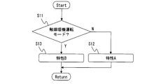
- step 11 it is determined whether or not the operating condition of the internal combustion engine 1 is the catalyst warm-up operation mode, and the characteristics of the overlap voltage supply time are selected based on this determination.
- the catalyst warm-up operation mode is an operation mode in which the ignition timing is forcibly retarded for early activation of the catalyst after the cold start.
- a relatively short characteristic A as illustrated in FIG. 5 is selected. If it is the catalyst warm-up operation mode, the process proceeds to step 13, and a relatively long characteristic B as illustrated in FIG. 5 is selected as the overlap voltage supply time from the start of discharge. In this embodiment, the overlap voltage supply time is switched regardless of the actual ignition timing ⁇ .
- step 21 the ignition timing ⁇ set according to the operating conditions of the internal combustion engine 1 is read.
- step 22 it is determined whether or not the set ignition timing ⁇ is retarded from a predetermined ignition timing threshold ⁇ a.
- step 22 that is, if the ignition timing ⁇ is on the more advanced side than the threshold value ⁇ a, the process proceeds to step 23, and the basic voltage exemplified as characteristic A in FIGS. Select the overlap voltage supply time.
- step 22 If YES in step 22, that is, if the ignition timing ⁇ is retarded from the threshold ⁇ a, the process proceeds to step 24 to estimate or calculate the gas flow velocity in the vicinity of the electrode of the spark plug 9 at the ignition timing ⁇ .
- the ignition timing ⁇ and the rotation speed at that time are obtained as parameters.
- the gas flow velocity in the vicinity of the electrode with respect to the ignition timing ⁇ has characteristics as shown in FIG. 10, and therefore the gas flow velocity can be obtained from a three-dimensional map including the rotation speed as a parameter.
- other parameters such as the intake air amount and the intake air temperature can be additionally used.
- the threshold value ⁇ a is set as shown in FIG. 10, for example, but in the present embodiment, the threshold value ⁇ a may be further set on the advance side.
- the overlap voltage supply time is set based on the gas flow rate obtained in step 24. For example, based on the characteristics shown in FIG. 11, the overlap voltage supply time is switched to two stages so that the overlap voltage supply time is long in the region where the gas flow rate is low. It should be noted that the gas flow rate that becomes the boundary at which the superposed voltage supply time is switched substantially corresponds to the gas flow rate when the ignition timing ⁇ is at the threshold ⁇ a under the engine rotation speed during steady operation. Further, the length of the overlap voltage supply time set relatively short in the region where the gas flow rate is high is substantially equal to the length of the basic overlap voltage supply time set in step 23.
- FIG. 12 shows a modification of the characteristics of the overlap voltage supply time with respect to the gas flow rate.
- the overlapping voltage supply time continuously changes according to the gas flow rate. That is, the lower the gas flow rate, the longer the overlap voltage supply time is given.
- the discharge time can be more appropriately given to the decrease in the gas flow accompanying the retard of the ignition timing.
- step 31 the ignition timing ⁇ set according to the operating condition of the internal combustion engine 1 is read.
- step 32 it is determined whether or not the set ignition timing ⁇ is retarded from a predetermined ignition timing threshold value ⁇ a. judge. If the ignition timing ⁇ is on the more advanced side than the threshold ⁇ a, the process proceeds to step 33, and the characteristic A shown in FIGS. 5 to 6 is selected as the overlap voltage supply time from the start of discharge.
- the routine proceeds to step 34, and the characteristic B shown in FIGS. 5 to 6 is selected as the overlap voltage supply time.
- step 34 the process further proceeds from step 34 to step 35, and the voltage value of the superposed voltage to be supplied is lowered.
- (3) in FIG. 7 shows a waveform of a secondary current and the like when the voltage value of the overlap voltage is lowered in this way.
- the current value of the secondary current decreases due to the decrease in the overlap voltage, and the discharge time is longer than the characteristic of the secondary current when supplying the overlap voltage of the characteristic A shown in (1) of FIG.
- the secondary current during the discharge period is low.
- the supply of the superposed voltage is used in order to lengthen the discharge time while maintaining the discharge current peak value at the same value.
- the present invention is not limited to the supply of such superposed voltage.
- the discharge time may be increased while maintaining the discharge current peak value equal by other means.
Landscapes
- Engineering & Computer Science (AREA)
- Chemical & Material Sciences (AREA)
- Combustion & Propulsion (AREA)
- Mechanical Engineering (AREA)
- General Engineering & Computer Science (AREA)
- Physics & Mathematics (AREA)
- Plasma & Fusion (AREA)
- Theoretical Computer Science (AREA)
- Signal Processing (AREA)
- Ignition Installations For Internal Combustion Engines (AREA)
Abstract
点火ユニット(11)は、点火コイル(15)に加えて、点火プラグ(9)の電極間に放電電圧と同方向の重ね電圧を重畳する重ね電圧生成回路(17)を有する。触媒暖機などのために点火時期(θ)が遅角されると、電極近傍のガス流速が低下し、火炎核が成長しないので、設定された点火時期(θ)が閾値(θa)よりも遅角側のときには、進角時に比較して、重ね電圧供給時間を長く設定する。これにより、容量放電に伴う放電電流ピーク値を同等に維持したまま放電時間を長くすることができ、効果的に着火性が改善する。
Description
この発明は、一次コイルおよび二次コイルを含む点火コイルを用いた内燃機関の点火装置および点火方法に関する。
点火コイルを用いた点火装置にあっては、一次コイルに一次電流を通電した後、所定の点火時期に一次電流を遮断することで、二次コイルに高い放電電圧を生成し、二次コイルに接続された点火プラグの電極間に放電を生じさせる。二次コイルに生じる放電電圧ならびに放電エネルギは、基本的には一次コイルへの通電時間に応じたものとなる。
特許文献1には、内燃機関の始動時や暖機完了前に、一次コイルへの通電時間を長めに設定し、大きな点火エネルギを得るようにすることが開示されている。
また、特許文献2には、放電期間を長くして確実な着火を得るために、点火時期後の放電期間に重ねて、別の昇圧回路による重ね電圧を点火プラグに与える技術が開示されている。このものでは、点火コイルによる二次電圧によって電極間の放電が開始した後、重ね電圧によって放電電流が継続される。
内燃機関の冷間始動後、触媒暖機のために点火時期を遅角制御する技術が知られているが、スワールやタンブルとして筒内に生成されたガス流動は、ピストンが上死点に近付くに従って崩壊するため、点火時期が遅角側となるほど、点火プラグの電極近傍におけるガス流速が低くなる。ガス流動の存在下では、放電時に電極間に生じた放電路がガス流動によって略U字形をなすように下流側へ拡がっていくため、初期火炎核が大きく得られ、着火性が高く得られる。これに対し、点火時期が遅角してガス流動が弱くなると、放電路が拡張せずに電極ギャップ内に留まるため、初期火炎核が小さくなってしまい、着火性が悪化する。
特許文献1では、内燃機関の暖機運転中に、点火エネルギ増大のために一次コイルへの通電時間を長く設定する構成となっているが、このように一次コイルへの通電時間を長くすると、放電時間の拡大と同時に、容量放電の際の放電電流ピーク値が高くなる。しかし、この放電電流ピーク値の増加は、点火時期遅角時(つまりガス流動の喪失時)における着火性改善には寄与しない。従って、無駄な放電エネルギの消費となり、また点火プラグの耐久性低下を招く懸念があり、好ましくない。
なお、特許文献2には、点火時期と放電時間との関係について何ら開示がない。
本発明に係る内燃機関の点火装置および点火方法は、点火コイルの一次コイルに一次電流を通電しかつ遮断することで、二次コイルに接続された点火プラグの電極間に放電電圧を発生させる内燃機関の点火装置ないし点火方法において、
点火時期を遅角側とするときに、放電電流ピーク値を同等に維持したまま放電時間を長く制御する。
点火時期を遅角側とするときに、放電電流ピーク値を同等に維持したまま放電時間を長く制御する。
点火時期の遅角に伴い、点火プラグの電極近傍のガス流動が弱くなり、ガス流動による放電路の拡張作用が失われる。つまり、放電路が電極間のギャップ内に留まるようになるが、本発明では、放電時間を長くすることで、放電期間中の放電路におけるガス交換量が増えるため、結果として、放電期間中に形成される初期火炎核の総量が増え、着火性が向上する。
特に、本発明では、非遅角時つまり点火時期がMBT点付近にあるときに比較して、放電電流ピーク値を同等に維持したまま放電時間のみを長くすることで、無駄な放電エネルギの消費や点火プラグの耐久性低下を回避しつつ、点火時期遅角時の着火性の改善が可能となる。
以下、この発明の一実施例を図面に基づいて詳細に説明する。
図1は、この発明に係る点火装置を備えた内燃機関1のシステム構成を示す構成説明図であって、内燃機関1の複数のシリンダ2の各々には、ピストン3が配置されているとともに、吸気弁4によって開閉される吸気ポート5および排気弁6によって開閉される排気ポート7がそれぞれ接続されている。また、筒内に燃料を噴射供給する燃料噴射弁8が配置されている。この燃料噴射弁8の燃料噴射時期および燃料噴射量は、エンジンコントロールユニット(ECU)10によって制御される。そして、上記燃料噴射弁8によって筒内に生成された混合気の点火を行うために、例えば天井面中央に点火プラグ9が配置されている。なお、図示例は、筒内直接噴射式内燃機関として構成されているが、吸気ポート5に燃料噴射弁を配置したポート噴射型の構成であってもよい。上記エンジンコントロールユニット10には、吸入空気量を検出するエアフロメータ21、機関回転速度を検出するクランク角センサ22、冷却水温を検出する温度センサ23、などの多数のセンサ類からの検出信号が入力されている。
上記点火プラグ9には、エンジンコントロールユニット10からの点火信号に応答して点火プラグ9に放電電圧を出力する点火ユニット11が接続されている。また、エンジンコントロールユニット10からの重ね電圧要求信号に応答して点火ユニット11による重ね電圧を制御する重ね電圧制御ユニット12が設けられている。これらのエンジンコントロールユニット10、点火ユニット11、および重ね電圧制御ユニット12は、車載の14ボルトのバッテリ13に接続されている。
上記点火ユニット11は、図2に詳細を示すように、一次コイルおよび二次コイル(図示せず)を含む点火コイル15と、この点火コイル15の一次コイルに対する一次電流の通電・遮断を制御するイグナイタ16と、昇圧回路を含む重ね電圧生成回路17と、を含んでおり、上記点火コイル15の二次コイルに点火プラグ9が接続されている。重ね電圧生成回路17は、バッテリ13の電圧を所定の重ね電圧の電圧まで昇圧した上で、重ね電圧制御ユニット12の制御信号に基づいて、点火プラグ9の放電開始後に該点火プラグ9に対し重ね電圧を出力する。重ね電圧生成回路17は、一次コイルへの一次電流遮断時に点火プラグ9の電極間に生じる本来の放電電圧と同じ電位の方向に重ね電圧を生成する。なお、図示例では、点火ユニット11の内部に点火コイル15とともに重ね電圧生成回路17が内蔵されているが、点火ユニット11とは別に重ね電圧生成回路17を備えた構成であってもよい。
図3は、重ね電圧の有無による二次電流(放電電流)の変化を説明するものであり、重ね電圧の非供給時と供給時について、一次電流(一次コイル通電信号)、重ね電圧、二次電圧、二次電流、のそれぞれの波形をまとめて図示している。
重ね電圧の非供給時には、一般的な点火装置と同様の作用となる。すなわち、点火コイル15の一次コイルに、イグナイタ16を介して所定の通電時間の間、一次電流が通電される。この一次電流の遮断に伴って、二次コイルには高い放電電圧が発生し、混合気の絶縁破壊を伴って点火プラグ9の電極間で放電が生じる。詳しくは、極めて高い電圧の容量放電が瞬間的に生じ、これに続いて誘導放電が生じる。そして、誘導放電の間、電極間に流れる二次電流は、放電開始から時間経過に伴って三角波状に比較的急激に減少していく。
これに対し、重ね電圧の供給時には、一次電流の遮断とほぼ同時に重ね電圧の供給が開始され、かつ所定の期間、一定の重ね電圧が重畳される。これにより、図示するように、放電開始から比較的長い期間、二次電流が高いレベルで継続する。
本実施例は、このような重ね電圧を利用して、点火時期遅角時の着火性改善を行う。
図4のフローチャートは、エンジンコントロールユニット10によって実行される点火制御の第1実施例を示している。ステップ1では、内燃機関1の運転条件に応じて設定された点火時期θを読み込む。点火時期θは、例えば、内燃機関1の負荷および回転速度をパラメータとしたマップに基づいて基本点火時期を求めた上で、排気系の触媒暖機のための遅角制御やノッキング回避のための遅角制御などの補正を加えて、最終的に決定される。
ステップ2では、設定された点火時期θが所定の点火時期閾値θaよりも遅角側であるか否かを判定する。点火時期閾値θaは、点火プラグ9の電極近傍のガス流動が着火性に悪影響を与える程度に弱くなる時期に対応しており、例えば、上死点付近のあるクランク角に固定的に設定してもよく、あるいは、基本点火時期などを考慮して可変的に設定してもよい。
ステップ2でNOつまり点火時期θが閾値θaよりも進角側にある場合は、ステップ3へ進み、放電開始からの重ね電圧供給時間として、図5に示す特性Aを選択する。ステップ2でYESつまり点火時期θが閾値θaよりも遅角側にある場合は、ステップ4へ進み、重ね電圧供給時間として、図5に示す特性Bを選択する。
図5は、重ね電圧供給時間と点火時期θとの関係を図示したものであり、この図5の例では、特性Aおよび特性Bは、それぞれ一定値となっているが、特性Bの重ね電圧供給時間は、特性Aの重ね電圧供給時間よりも相対的に長い時間となっている。つまり、設定された点火時期θに応じて、重ね電圧供給時間が2段階に変化する。
図7の(1)は、特性Aに沿って重ね電圧供給時間が比較的短く制御された場合の二次電圧等の波形を示しており、図7の(2)は、特性Bに沿って重ね電圧供給時間が比較的長く制御された場合の波形を示している。これらの比較から明らかなように、重ね電圧供給時間を長くすることで、二次電流として高電流の持続時間が長くなり、ガス流動が弱い条件下での着火性改善が図れる。特に、図7から明らかなように、重ね電圧の供給時間の変更によって、容量放電の際の放電電流ピーク値を同等に維持したまま放電時間のみを長くすることができ、無駄な放電エネルギの消費や点火プラグの耐久性低下を回避しつつ、点火時期遅角時の着火性の改善が可能である。
図6は、点火時期θが閾値θaよりも遅角側にあるときの特性Bの変形例を示している。この図6の例では、重ね電圧供給時間が点火時期θに応じて与えられ、点火時期θが遅角側であるほど重ね電圧供給時間が長く与えられる。このように点火時期θに応じて重ね電圧供給時間を設定すれば、点火時期の遅角に伴うガス流動の低下に対し、より適切に放電時間を与えることができる。
次に、図8のフローチャートは、点火制御の第2実施例を示している。この実施例では、ステップ11において、内燃機関1の運転条件が触媒暖機運転モードであるか否かを判定し、この判定に基づいて重ね電圧供給時間の特性を選択する。触媒暖機運転モードは、冷間始動後に触媒の早期活性化のために点火時期を強制的に遅角する運転モードであり、触媒暖機運転モードでなければステップ12へ進み、放電開始からの重ね電圧供給時間として、図5に例示するような相対的に短い特性Aを選択する。触媒暖機運転モードであれば、ステップ13へ進み、放電開始からの重ね電圧供給時間として、図5に例示するような相対的に長い特性Bを選択する。この実施例では、実際の点火時期θに拘わらず、重ね電圧供給時間の切換が行われる。
次に、図9のフローチャートは、点火制御の第3実施例を示している。ステップ21では、内燃機関1の運転条件に応じて設定された点火時期θを読み込む。ステップ22では、設定された点火時期θが所定の点火時期閾値θaよりも遅角側であるか否かを判定する。
ステップ22でNOつまり点火時期θが閾値θaよりも進角側にある場合は、ステップ23へ進み、放電開始からの重ね電圧供給時間として、図5ないし図6に特性Aとして例示した基本的な重ね電圧供給時間を選択する。
ステップ22でYESつまり点火時期θが閾値θaよりも遅角側にある場合は、ステップ24へ進み、点火時期θにおける点火プラグ9の電極近傍のガス流速を推定ないし演算する。これは、そのときの点火時期θと回転速度とをパラメータとして求める。例えば、点火時期θに対して電極近傍のガス流速は、図10に示すような特性を有するので、回転速度をパラメータとして含む三次元マップからガス流速を求めることができる。ガス流速の推定精度を高めるために、吸入空気量や吸気温などの他のパラメータを付加的に用いることも可能である。なお、閾値θaは、例えば図10に示すように設定されるが、本実施例では、さらに進角側に閾値θaを設定するようにしてもよい。
ステップ25では、ステップ24で求めたガス流速に基づいて、重ね電圧供給時間を設定する。例えば、図11に示す特性に基づき、ガス流速が低い領域では重ね電圧供給時間が長いものとなるように、重ね電圧供給時間を2段階に切り換える。なお、重ね電圧供給時間が切り換えられる境界となるガス流速は、定常運転時の機関回転速度の下で点火時期θが閾値θaにあるときのガス流速にほぼ対応している。また、ガス流速が高い領域で相対的に短く設定される重ね電圧供給時間の長さは、ステップ23で設定される基本的な重ね電圧供給時間の長さと実質的に等しい。
図12は、ガス流速に対する重ね電圧供給時間の特性の変形例を示している。この図12の例では、ガス流速が比較的小さい領域において、重ね電圧供給時間がガス流速に応じて連続的に変化する特性となっている。つまり、ガス流速が低いほど重ね電圧供給時間が長く与えられる。このようにガス流速に応じて重ね電圧供給時間を設定すれば、点火時期の遅角に伴うガス流動の低下に対し、より適切に放電時間を与えることができる。
次に、図13のフローチャートは、点火制御の第4実施例を示している。図のステップ31~34は、図4の第1実施例のステップ1~4と実質的に変わりがない。ステップ31で、内燃機関1の運転条件に応じて設定された点火時期θを読み込み、ステップ32で、設定された点火時期θが所定の点火時期閾値θaよりも遅角側であるか否かを判定する。点火時期θが閾値θaよりも進角側にある場合は、ステップ33へ進み、放電開始からの重ね電圧供給時間として、図5ないし図6に示す特性Aを選択する。点火時期θが閾値θaよりも遅角側にある場合は、ステップ34へ進み、重ね電圧供給時間として、図5ないし図6に示す特性Bを選択する。
ここで、本実施例では、さらにステップ34からステップ35へ進み、供給する重ね電圧の電圧値を低下させる。図7の(3)は、このように重ね電圧の電圧値を低下させたときの二次電流等の波形を示している。図示するように、重ね電圧の低下により二次電流の電流値が低くなり、図7の(1)に示す特性Aの重ね電圧供給時における二次電流の特性に比較して、放電時間が長く、かつ放電期間中の二次電流が低い特性となる。
点火時期遅角に伴うガス流動の弱い条件下では、電流値の増大は着火性に寄与しない。従って、本実施例では、放電期間中の電流値を低下させつつ放電時間を長くすることで、無駄に放電エネルギを消費することなく点火時期遅角時の着火性を効果的に改善することができる。
以上、この発明の一実施例を詳細に説明したが、この発明は上記の実施例に限定されるものではなく、種々の変更が可能である。上記実施例では、放電電流ピーク値を同等に維持したまま放電時間を長くするために重ね電圧の供給を利用しているが、本発明は、このような重ね電圧の供給を行うものに限らず、他の手段により放電電流ピーク値を同等に維持したまま放電時間を長くする構成であってもよい。
Claims (8)
- 点火コイルの一次コイルに一次電流を通電しかつ遮断することで、二次コイルに接続された点火プラグの電極間に放電電圧を発生させる内燃機関の点火装置において、
点火時期を遅角側とするときに、放電電流ピーク値を同等に維持したまま放電時間を長く制御する内燃機関の点火装置。 - 内燃機関の触媒暖機のための点火時期遅角制御のときに上記の放電時間の延長を行う、請求項1に記載の内燃機関の点火装置。
- 点火時期が所定クランク角よりも遅角側であるときに上記の放電時間の延長を行う、請求項1または2に記載の内燃機関の点火装置。
- 上記二次コイルによる放電開始後に上記点火プラグの電極間に上記放電電圧と同方向の重ね電圧を加えて放電電流を継続させる重ね電圧生成回路を有し、
この重ね電圧生成回路による重ね電圧供給時間を、点火時期の遅角制御のときに長く設定する、請求項1~3のいずれかに記載の内燃機関の点火装置。 - 点火時期が遅角側にあるほど重ね電圧供給時間を長く設定する、請求項4に記載の内燃機関の点火装置。
- 点火時期における点火プラグの電極近傍のガス流速を求め、このガス流速が低いほど重ね電圧供給時間を長く設定する、請求項4に記載の内燃機関の点火装置。
- 重ね電圧供給時間を長くするときに、重ね電圧の電圧値を低くする、請求項4~6のいずれかに記載の内燃機関の点火装置。
- 点火コイルの一次コイルに一次電流を通電しかつ遮断することで、二次コイルに接続された点火プラグの電極間に放電電圧を発生させる内燃機関の点火方法において、
点火時期を遅角側とするときに、放電電流ピーク値を同等に維持したまま放電時間を長く制御する内燃機関の点火方法。
Priority Applications (1)
| Application Number | Priority Date | Filing Date | Title |
|---|---|---|---|
| PCT/JP2014/053600 WO2015122003A1 (ja) | 2014-02-17 | 2014-02-17 | 内燃機関の点火装置および点火方法 |
Applications Claiming Priority (1)
| Application Number | Priority Date | Filing Date | Title |
|---|---|---|---|
| PCT/JP2014/053600 WO2015122003A1 (ja) | 2014-02-17 | 2014-02-17 | 内燃機関の点火装置および点火方法 |
Publications (1)
| Publication Number | Publication Date |
|---|---|
| WO2015122003A1 true WO2015122003A1 (ja) | 2015-08-20 |
Family
ID=53799766
Family Applications (1)
| Application Number | Title | Priority Date | Filing Date |
|---|---|---|---|
| PCT/JP2014/053600 Ceased WO2015122003A1 (ja) | 2014-02-17 | 2014-02-17 | 内燃機関の点火装置および点火方法 |
Country Status (1)
| Country | Link |
|---|---|
| WO (1) | WO2015122003A1 (ja) |
Cited By (3)
| Publication number | Priority date | Publication date | Assignee | Title |
|---|---|---|---|---|
| JP2015200265A (ja) * | 2014-04-10 | 2015-11-12 | 株式会社日本自動車部品総合研究所 | 内燃機関の点火制御装置 |
| JP2017106371A (ja) * | 2015-12-09 | 2017-06-15 | 株式会社Soken | 内燃機関の制御装置 |
| US10563602B2 (en) | 2017-12-06 | 2020-02-18 | Toyota Jidosha Kabushiki Kaisha | Controller and control method for internal combustion engine |
Citations (5)
| Publication number | Priority date | Publication date | Assignee | Title |
|---|---|---|---|---|
| JPS59103968A (ja) * | 1982-12-06 | 1984-06-15 | Nissan Motor Co Ltd | 内燃機関用点火装置 |
| JPS60169675A (ja) * | 1984-02-13 | 1985-09-03 | Nissan Motor Co Ltd | 内燃機関用点火装置 |
| JP2009299574A (ja) * | 2008-06-12 | 2009-12-24 | Nippon Soken Inc | エンジンの制御装置 |
| JP2010025073A (ja) * | 2008-07-24 | 2010-02-04 | Denso Corp | 内燃機関の制御装置及び制御システム |
| JP2011117356A (ja) * | 2009-12-03 | 2011-06-16 | Denso Corp | 筒内噴射式内燃機関 |
-
2014
- 2014-02-17 WO PCT/JP2014/053600 patent/WO2015122003A1/ja not_active Ceased
Patent Citations (5)
| Publication number | Priority date | Publication date | Assignee | Title |
|---|---|---|---|---|
| JPS59103968A (ja) * | 1982-12-06 | 1984-06-15 | Nissan Motor Co Ltd | 内燃機関用点火装置 |
| JPS60169675A (ja) * | 1984-02-13 | 1985-09-03 | Nissan Motor Co Ltd | 内燃機関用点火装置 |
| JP2009299574A (ja) * | 2008-06-12 | 2009-12-24 | Nippon Soken Inc | エンジンの制御装置 |
| JP2010025073A (ja) * | 2008-07-24 | 2010-02-04 | Denso Corp | 内燃機関の制御装置及び制御システム |
| JP2011117356A (ja) * | 2009-12-03 | 2011-06-16 | Denso Corp | 筒内噴射式内燃機関 |
Cited By (3)
| Publication number | Priority date | Publication date | Assignee | Title |
|---|---|---|---|---|
| JP2015200265A (ja) * | 2014-04-10 | 2015-11-12 | 株式会社日本自動車部品総合研究所 | 内燃機関の点火制御装置 |
| JP2017106371A (ja) * | 2015-12-09 | 2017-06-15 | 株式会社Soken | 内燃機関の制御装置 |
| US10563602B2 (en) | 2017-12-06 | 2020-02-18 | Toyota Jidosha Kabushiki Kaisha | Controller and control method for internal combustion engine |
Similar Documents
| Publication | Publication Date | Title |
|---|---|---|
| JP5765493B2 (ja) | 内燃機関の点火装置および点火方法 | |
| JP4873250B2 (ja) | 車両用エンジンのプリイグニッション検出装置 | |
| CN113825900A (zh) | 内燃机用控制装置 | |
| JP6081248B2 (ja) | 内燃機関の点火制御装置 | |
| JP4938404B2 (ja) | エンジン制御装置 | |
| JP5843047B2 (ja) | 内燃機関の点火制御装置および点火制御方法 | |
| WO2015151482A1 (ja) | 筒内噴射式内燃機関の噴射制御装置 | |
| JP6392535B2 (ja) | 内燃機関の制御装置 | |
| JP4980807B2 (ja) | 内燃機関の制御装置 | |
| WO2014147795A1 (ja) | 内燃機関の制御装置 | |
| WO2015146126A1 (ja) | エンジンの点火制御装置 | |
| JP6022594B2 (ja) | エンジン制御システム | |
| JP2010025039A (ja) | 燃焼異常状態判別装置 | |
| US11754033B2 (en) | Ignition control device | |
| JP6248980B2 (ja) | 内燃機関の気流の流速算出装置 | |
| JP6622513B2 (ja) | 点火装置 | |
| JP2014206058A (ja) | 内燃機関の点火装置および点火方法 | |
| JP2022131765A (ja) | 点火制御装置 | |
| JP6411951B2 (ja) | 内燃機関の制御装置 | |
| JP6426365B2 (ja) | 内燃機関の点火制御装置 | |
| WO2014103555A1 (ja) | 内燃機関の点火装置および点火方法 | |
| JP2006152836A (ja) | 内燃機関 | |
| JP5998949B2 (ja) | 内燃機関の点火制御装置 | |
| JP4884516B2 (ja) | 内燃機関の点火制御装置 | |
| JP2016056684A (ja) | エンジン制御装置 |
Legal Events
| Date | Code | Title | Description |
|---|---|---|---|
| 121 | Ep: the epo has been informed by wipo that ep was designated in this application |
Ref document number: 14882705 Country of ref document: EP Kind code of ref document: A1 |
|
| NENP | Non-entry into the national phase |
Ref country code: DE |
|
| 122 | Ep: pct application non-entry in european phase |
Ref document number: 14882705 Country of ref document: EP Kind code of ref document: A1 |
|
| NENP | Non-entry into the national phase |
Ref country code: JP |