WO2015118735A1 - パンツ型の吸収性物品 - Google Patents
パンツ型の吸収性物品 Download PDFInfo
- Publication number
- WO2015118735A1 WO2015118735A1 PCT/JP2014/078772 JP2014078772W WO2015118735A1 WO 2015118735 A1 WO2015118735 A1 WO 2015118735A1 JP 2014078772 W JP2014078772 W JP 2014078772W WO 2015118735 A1 WO2015118735 A1 WO 2015118735A1
- Authority
- WO
- WIPO (PCT)
- Prior art keywords
- absorbent article
- opening
- bonding strength
- joint
- type absorbent
- Prior art date
- Legal status (The legal status is an assumption and is not a legal conclusion. Google has not performed a legal analysis and makes no representation as to the accuracy of the status listed.)
- Ceased
Links
Images




Classifications
-
- A—HUMAN NECESSITIES
- A61—MEDICAL OR VETERINARY SCIENCE; HYGIENE
- A61F—FILTERS IMPLANTABLE INTO BLOOD VESSELS; PROSTHESES; DEVICES PROVIDING PATENCY TO, OR PREVENTING COLLAPSING OF, TUBULAR STRUCTURES OF THE BODY, e.g. STENTS; ORTHOPAEDIC, NURSING OR CONTRACEPTIVE DEVICES; FOMENTATION; TREATMENT OR PROTECTION OF EYES OR EARS; BANDAGES, DRESSINGS OR ABSORBENT PADS; FIRST-AID KITS
- A61F13/00—Bandages or dressings; Absorbent pads
- A61F13/15—Absorbent pads, e.g. sanitary towels, swabs or tampons for external or internal application to the body; Supporting or fastening means therefor; Tampon applicators
- A61F13/45—Absorbent pads, e.g. sanitary towels, swabs or tampons for external or internal application to the body; Supporting or fastening means therefor; Tampon applicators characterised by the shape
- A61F13/49—Absorbent pads, e.g. sanitary towels, swabs or tampons for external or internal application to the body; Supporting or fastening means therefor; Tampon applicators characterised by the shape specially adapted to be worn around the waist, e.g. diapers or nappies
- A61F13/496—Absorbent pads, e.g. sanitary towels, swabs or tampons for external or internal application to the body; Supporting or fastening means therefor; Tampon applicators characterised by the shape specially adapted to be worn around the waist, e.g. diapers or nappies in the form of pants or briefs
- A61F13/4963—Absorbent pads, e.g. sanitary towels, swabs or tampons for external or internal application to the body; Supporting or fastening means therefor; Tampon applicators characterised by the shape specially adapted to be worn around the waist, e.g. diapers or nappies in the form of pants or briefs characterized by the seam
Definitions
- the abdomen side portion 11a and the back side portion 11b can be easily peeled off from the welded portion jm ′ located in the leg opening 1HL.
- the vicinity of the welded portion jm ′ in the diaper 1 ′ will be broken. Is easier to break when the basis weight (g / m 2 ) in the vicinity is smaller.
- the vicinity portion to be broken a portion 11HB forming the waist opening 1HB and a portion 11HL forming the leg opening 1HL.
- the bonding strength of the first portion closest to the leg opening is made smaller than the bonding strength of the predetermined portion. Therefore, while maintaining the joint strength of the joint portion as a whole to withstand the wearing of the absorbent article, the first portion located on the leg opening side of the joint portion as a starting point, The back side portion can be easily peeled off. That is, the abdominal side and the back side can be easily peeled off from the leg opening.
- each of the joints formed at the respective lateral ends is located on the leg opening side of the joint. It is possible to easily peel off the abdominal part and the dorsal part starting from the first part. Therefore, even if the worker who peels off selects either of the two leg opening parts, the worker can easily peel off the ventral part and the dorsal part, Thereby, the said operator can take off an absorbent article rapidly.
- the skin side surface of the absorbent core 3c is provided with a liquid-permeable top sheet 4 such as a nonwoven fabric so as to cover the entire surface, and similarly, on the non-skin side surface of the absorbent core 3c.
- a liquid-impermeable leak-proof sheet 5 such as a film so as to cover the entire surface.
- both the sheets 4 and 5 are formed in a substantially rectangular shape in plan view, and both the sheets 4 and 5 are outside the outer contour of the absorbent core 3c over the entire circumference. Is jumping out.
- the part which protruded in the top sheet 4 and the part which protruded in the leak-proof sheet 5 are mutually joined by adhesion
- the absorptive main body 3 of planar view substantially rectangular shape is formed. .
- a nonwoven fabric including a thermoplastic resin fiber, a thermoplastic resin film, or the like is used as the material of the other sheets 13a and 13b.
- a basis weight of 17 (g / m 2 ) including a thermoplastic resin fiber is used as the material of the other sheets 13a and 13b.
- An amount of spunbond nonwoven is used, but not limited to this.
- the above-described absorbent main body 3 is in a state in which the longitudinal directions thereof are aligned. It is fixed.
- the length in the longitudinal direction and the length in the width direction of the absorbent main body 3 are set such that the absorbent main body 3 can be generally accommodated inside the exterior sheet 11.
- a direction parallel to the width direction of the exterior sheet 11 is referred to as a “lateral direction”.
- a direction parallel to the longitudinal direction of the exterior sheet 11 is referred to as a “longitudinal direction”.
- the horizontal direction and the vertical direction are orthogonal to each other.
- a direction perpendicular to both the horizontal direction and the vertical direction is referred to as a “front-rear direction”.
- the front in the front-rear direction is the abdomen side that is the front side of the wearer, and the rear side in the front-rear direction is the back side that is the rear side of the wearer.
- junction part j is each formed along the vertical direction in each edge part of the abdominal side part 11a of the exterior sheet
- a junction j is also formed along the vertical direction at each end in the horizontal direction of 11b (FIG. 2). It should be noted that the joint j of the abdomen 11a and the joint j of the back 11b are integrated and are the same so-called so-called front and back positional relationships at the end. Therefore, no distinction is made in the following description.
- FIG. 6A is a schematic enlarged view of the joint j
- FIG. 6B is a schematic view taken along the line BB in FIG. 6A.
- the joint j extends from the waistline opening 1HB toward the leghole opening 1HL in the longitudinal direction.
- the joint j has a plurality of welded portions jm, jm... Formed in a longitudinal direction indented in the front-rear direction (direction passing through the paper surface in FIG. 6A), and the plurality of welded portions jm, jm.
- a welding pattern having a predetermined regularity For example, in this example, each welded portion jm is formed in a substantially rectangular shape that is long in the lateral direction with a space between each welded portion jm adjacent in the vertical direction.
- the welding part jm located in the lowest part of the vertical direction among the junction parts j, ie, the welding part jm (corresponding to the first part) closest to the leg opening 1HL among the junction parts j.
- the “joining strength” referred to here is a magnitude (N) of an external force required to peel off the abdominal portion 11a and the dorsal portion 11b along the vertical direction.
- the joint strength of the joint portion j as a whole can withstand the wearing of the diaper 1 based on the large joint strength of each of the plurality of welded portions jmc, jmc. While maintaining the size, the joint between the ventral portion 11a and the dorsal portion 11b can be released with a relatively small external force starting from the weld portion jmb positioned at the lowest position in the vertical direction. As a result, the abdomen portion 11a and the dorsal portion 11b can be quickly and easily peeled from the leg opening 1HL side.
- the welded portion jmb are made smaller than the bonding strength of each of the plurality of welded portions jmc, jmc. Therefore, regardless of which opening 1HL of the left and right leg opening 1HL, 1HL in FIG. 2 is selected by a diaper changing operator, the abdomen 11a and the back 11b are easily pulled. The worker can remove the diaper 1 promptly.
- the present invention is not limited to this. That is, only the joint portion j at one of the left and right end portions in the lateral direction may have the above specifications.
- the number of the plurality of welded portions jmc positioned at the central portion in the longitudinal direction where the lowermost welded portion jmb and the bonding strength (N) should be compared may be, for example, 2 to 20 pieces, Alternatively, it may be 5 to 15 pieces.
- the bonding strength (N) of the lowermost welded portion jmb is made smaller than the bonding strength (N) of each of the welded portions jmc, jmc.
- the joint strength (N) of jmb may be reduced.
- the longitudinal distribution of the bonding strength (N) at the bonded portion j can be measured, for example, as follows. First, while taking care not to cut the joint portion j, the lateral end of the exterior sheet 11 is separated from the diaper 1 into a strip shape that is long in the vertical direction, thereby forming a strip shape that is long in the vertical direction as shown in FIG. A measurement sample S is prepared. And when the part Njm in which the welding part jm is not formed exists in the longitudinal direction lower end part of the measurement sample S, the part Njm in which the welding part jm is not formed is taken as the ventral part 11a and the back side. These are used as a pair of knobs divided into parts 11b.
- one of the pair of knobs is chucked to one head of a tensile tester (not shown) (for example, AUTOGRAPH (model AG-1kNI) manufactured by Shimadzu Corporation) and the other knob is the same.
- Chuck to the other head of the testing machine.
- one head is a fixed head fixed to the tester so as not to move
- the other head is a moving head that is provided coaxially below the fixed head and is movable in the vertical direction.
- N tensile load value
- the abdomen portion 11a and the dorsal portion 11b of the measurement sample S are sequentially peeled off, that is, the position at which the measurement sample S is peeled off is the vertical direction from the lower end portion to the upper end portion of the measurement sample S.
- the measurement sample S is completely separated by the ventral part 11a and the dorsal part 11b, and that is the case. If so, the measurement ends.
- a pair of knobs may be formed on the upper end portion while sacrificing some welded portions jm, jm at the upper end portion in the vertical direction of S, and this may be peeled off from the upper end portion to the lower end portion.
- the joint strength (N) of the welded portion jmt) is also made smaller than the joint strength (N) of each of the welded portions jmc, jmc. good.
- the magnitude relationship between the bonding strength (N) of the welded portion jmb closest to the leg opening 1HL and the bonding strength (N) of the welded portion jmt closest to the trunk opening 1HB is mutually related.
- the same value may be used, or the former may be made smaller. Incidentally, if the former is made smaller, it can be easily peeled off from the leg opening 1HL.
- the area (m 2 ) of the welding portion jmb (jmt) to be reduced whose bonding strength (N) should be reduced is smaller than the area (m 2 ) of the welding portion jmc that is not the reduction target.
- the bonding force (N / m 2 ) per unit area of the welding portion jmb (jmt) to be reduced is determined as the bonding force (N / m 2 ) per unit area of the welding portion jmc not to be reduced.
- the joint strength (N) of the welded portion jmb (jmt) to be reduced is made smaller than the joint strength (N) of the welded portion jmc not to be reduced. Not exclusively.
- the ventral side portion 11a and the back side portion 11b may not be peeled off smoothly even at the waist opening 1HB. In that case, the operator of diaper replacement takes off the diaper 1 by breaking the exterior sheet 11 itself.
- the basis weight (g / m) of the portion 11HL that forms the leg opening 1HL in the exterior sheet 11 due to the folding of the ventral outer sheet 13a and the back outer sheet 13b at the trunk opening 1HB. 2 ) is smaller than the basis weight (g / m 2 ) of the portion 11HB forming the trunk periphery opening 1HB in the exterior sheet 11. Therefore, the operator of diaper replacement can tear the exterior sheet 11 itself relatively easily from the leg opening 1HL, and as a result, the diaper 1 replacement operation can be prevented from being stagnant.
- the welding strength (N) of one welded portion jmb closest to the leg opening 1HL is reduced, but the welded portion jm to be reduced in this joint strength is reduced.
- the number is not limited to one and may be plural.
- the weld portion jmb closest to the leg opening 1HL is the first weld jmb (corresponding to the first portion)
- the waist opening 1HL of the first weld jmb is the same as that of the first welded portion jmb. It may be smaller than the welded parts jmc, jmc.
- the bonding strength (N) of the first welded portion jmb and the second welded portion jmb2 may be aligned with each other, but may not be aligned.
- the joint strength of the second welded part jmb2 may be set to a magnitude between the joint strength of the first welded part jmb and the joint strength of each of the welded parts jmc located at the longitudinal center. And if it does in this way, about at least 2 welding part jmb and jmb2 located in the vicinity of the leg periphery opening part 1HL, joining strength becomes small as the welding part jm in the position near the leg periphery opening part 1HL. Yes. Therefore, the abdominal side portion 11a and the back side portion 11b can be peeled off smoothly from the leg opening 1HL.
- the bonding strength of one welded portion jmt closest to the waistline opening 1HB may be reduced, but the number of welded portions jm to be reduced in this bonding strength. Is not limited to one, but may be plural.
- the welded part jmt closest to the waistline opening 1HB is the third welded part jmt (corresponding to the third part)
- the welded part jm adjacent to the leg-holed opening 1HL side of the third welded part jmt when the welded part jmt closest to the waistline opening 1HB is the third welded part jmt (corresponding to the third part), the welded part jm adjacent to the leg-holed opening 1HL side of the third welded part jmt.
- the joint strength of (corresponding to the fourth portion, hereinafter also referred to as the fourth welded portion jmt4) may be reduced in the same manner as the third welded portion jmt.
- the joint strength (N) of the third welded portion jmt and the fourth welded portion jmt4 may be aligned with each other, but may not be aligned.
- the joint strength of the fourth welded portion jmt4 may be set to a magnitude between the joint strength of the third welded portion jmt and the joint strength of each of the welded portions jmc located at the longitudinal center. And if it does in this way, about at least 2 welding part jmt and jmt4 located in the vicinity of the trunk periphery opening part 1HB, the joint strength jm of the position close
- the formation of the joint j having such welds jm, jm... Is realized by an appropriate ultrasonic welding device (not shown).
- the ultrasonic welding apparatus welds the welding target portion by frictional heat generation by supplying ultrasonic energy to the welding target portion. And the welded part remains on the exterior sheet 11 as welded parts jm, jm.
- Such an ultrasonic welding apparatus has, for example, a rail-shaped horn extending in a direction corresponding to the vertical direction (hereinafter also referred to as a CD direction).
- the horn has an oscillation surface that performs ultrasonic vibration.
- the oscillation surface has a belt-like plane extending in the CD direction, and ultrasonically vibrates at a predetermined frequency such as 20 to 35 kHz in the normal direction.
- the apparatus also has a roller-shaped anvil (hereinafter referred to as an anvil roller) that can roll the belt-like plane of the horn in the CD direction.
- anvil roller On the outer peripheral surface of the anvil roller, a plurality of protrusions are provided in correspondence with the formation pattern of the welded portions jm, jm.
- the exterior sheet 11 is placed on a belt-like plane that is the oscillation surface of the horn so that the longitudinal direction of the exterior sheet 11 folded in two to form a pants shape is aligned with the CD direction, and the horn is subjected to ultrasonic vibration. While the anvil roller is traversing the exterior sheet 11 along the CD direction, a plurality of welded parts jm, jm... Are formed on the exterior sheet 11 as joints j. At the time of crossing, the ultrasonic energy (J / m) input per unit length in the CD direction is adjusted so as to be small at the portion of the exterior sheet 11 that is closest to the leg opening 1HL.
- a substantially rectangular welded portion jm that is long in the horizontal direction is illustrated as shown in FIG.
- the shape of is not limited to this.
- it may be oval or circular.
- the welding pattern formed as a whole by the plurality of welded portions jm, jm... Is not limited to a simple vertically arranged pattern in which the welded portions jm, jm.
Landscapes
- Health & Medical Sciences (AREA)
- Epidemiology (AREA)
- Engineering & Computer Science (AREA)
- Biomedical Technology (AREA)
- Heart & Thoracic Surgery (AREA)
- Vascular Medicine (AREA)
- Life Sciences & Earth Sciences (AREA)
- Animal Behavior & Ethology (AREA)
- General Health & Medical Sciences (AREA)
- Public Health (AREA)
- Veterinary Medicine (AREA)
- Absorbent Articles And Supports Therefor (AREA)
Abstract
装着時に着用者の腹側に配される腹側部と、前記着用者の背側に配される背側部と、前記着用者の股間に配される股下部とを有した吸収性物品を、前記股下部にて二つ折りして前記腹側部と前記背側部とを重ね合わせた状態で、前記腹側部と前記背側部とを横方向の各端部でそれぞれ接合することにより、胴回り開口部と一対の脚回り開口部とが形成されたパンツ型の吸収性物品である。前記腹側部と前記背側部とを接合するために前記横方向の前記各端部に形成された各接合部は、それぞれ、前記胴回り開口部の方から前記脚回り開口部の方へと延在している。前記各接合部のうちの少なくとも一方の接合部のうちで前記脚回り開口部に最も近い第1部分の接合強度は、前記接合部のうちで前記第1部分と前記胴回り開口部との間に位置する所定部分の接合強度よりも小さい。
Description
本発明は、尿等の排泄液を吸収するパンツ型の吸収性物品に関する。
従来、尿等の排泄液を吸収する吸収性物品として、パンツ型の使い捨ておむつが使用されている。このおむつは、装着時に着用者の腹側に配される腹側部と、同着用者の背側に配される背側部と、同着用者の股間に配される股下部とを有する。そして、かかるおむつを股下部にて二つ折りして腹側部と背側部とを重ね合わせた状態で、腹側部と背側部とを横方向の各端部でそれぞれ接合することにより、胴回り開口部と一対の脚回り開口部とが形成されたパンツ型のおむつの形にして、ユーザーに提供している。
特許文献1には、このパンツ型のおむつの一例が開示されている。図1Aは、同おむつ1’の横方向の端部の概略拡大図であり、また、図1Bは、図1A中のB-B矢視の概略図である。図1Aに示すように、このおむつ1’にあっては、上述の腹側部11aと背側部11bとの接合に伴って、当該腹側部11a及び背側部11bの横方向の各端部には、それぞれ接合部jが形成されている。そして、接合部jは、胴回り開口部1HBの方から脚回り開口部1HLの方へと延在している。また、排泄したおむつ1’を着用者から脱がす際には、上記の接合部j’において腹側部11aと背側部11bとを引き剥がして、着用者からおむつ1’を取り外すことがなされる。
ここで、同特許文献1には、かかる接合部j’の一例として、横方向に長い横長矩形形状の溶着部jm’,jm’…が胴回り開口部1HBから脚回り開口部1HLまでに亘って複数並んでなる接合部j’が開示されており、また、胴回り開口部1HBの近傍位置では、溶着部jm’の横方向の長さを短くすることが図示されている。
そして、かかるおむつ1’によれば、胴回り開口部1HBの近傍の溶着部jm’については、横方向の長さが短くされている。そのため、当該位置での接合強度(N)は小さいと考えられて、故に、胴回り開口部1HBに位置する溶着部jm’を起点として腹側部11aと背側部11bとを比較的容易に引き剥がすことが可能と考えられる。
しかしながら、場合によっては、脚回り開口部1HLに位置する溶着部jm’を起点として腹側部11aと背側部11bとを容易に引き剥がせる方が好ましいケースも存在すると考えられる。
例えば、仮に溶着部jm’において腹側部11aと背側部11bとを引き剥がすことが困難な場合には、おむつ1’における溶着部jm’の近傍部分を破ることになるが、その場合には、かかる近傍部分の坪量(g/m2)が小さい方が破り易い。そして、破るべき近傍部分の候補としては、胴回り開口部1HBをなす部分11HBと脚回り開口部1HLをなす部分11HLとの二つが挙げられるが、ここで、図1Bに示すように、胴回り開口部1HBをなす部分11HBは、一般にシートの折り返しなどに起因して、脚回り開口部1HLをなす部分11HLよりも坪量(g/m2)が大きくなっている。そのため、脚回り開口部1HLをなす部分11HLの方が破り易いことが多く、このようなことから、かかる場合には、脚回り開口部1HLを起点として腹側部11aと背側部11bとを容易に引き剥がせると便利なものと考えられるのである。
例えば、仮に溶着部jm’において腹側部11aと背側部11bとを引き剥がすことが困難な場合には、おむつ1’における溶着部jm’の近傍部分を破ることになるが、その場合には、かかる近傍部分の坪量(g/m2)が小さい方が破り易い。そして、破るべき近傍部分の候補としては、胴回り開口部1HBをなす部分11HBと脚回り開口部1HLをなす部分11HLとの二つが挙げられるが、ここで、図1Bに示すように、胴回り開口部1HBをなす部分11HBは、一般にシートの折り返しなどに起因して、脚回り開口部1HLをなす部分11HLよりも坪量(g/m2)が大きくなっている。そのため、脚回り開口部1HLをなす部分11HLの方が破り易いことが多く、このようなことから、かかる場合には、脚回り開口部1HLを起点として腹側部11aと背側部11bとを容易に引き剥がせると便利なものと考えられるのである。
本発明は、上記のような従来の問題に鑑みてなされたものであって、その目的は、脚回り開口部を起点として腹側部と背側部とを容易に引き剥がし可能にすることにある。
上記目的を達成するための主たる発明は、
装着時に着用者の腹側に配される腹側部と、前記着用者の背側に配される背側部と、前記着用者の股間に配される股下部とを有した吸収性物品を、前記股下部にて二つ折りして前記腹側部と前記背側部とを重ね合わせた状態で、前記腹側部と前記背側部とを横方向の各端部でそれぞれ接合することにより、胴回り開口部と一対の脚回り開口部とが形成されたパンツ型の吸収性物品であって、
前記腹側部と前記背側部とを接合するために前記横方向の前記各端部に形成された各接合部は、それぞれ、前記胴回り開口部の方から前記脚回り開口部の方へと延在しており、
前記各接合部のうちの少なくとも一方の接合部のうちで前記脚回り開口部に最も近い第1部分の接合強度は、前記接合部のうちで前記第1部分と前記胴回り開口部との間に位置する所定部分の接合強度よりも小さいことを特徴とするパンツ型の吸収性物品である。
本発明の他の特徴については、本明細書及び添付図面の記載により明らかにする。
本発明によれば、脚回り開口部を起点として腹側部と背側部とを容易に引き剥がし可能となる。
本明細書及び添付図面の記載により、少なくとも以下の事項が明らかとなる。
装着時に着用者の腹側に配される腹側部と、前記着用者の背側に配される背側部と、前記着用者の股間に配される股下部とを有した吸収性物品を、前記股下部にて二つ折りして前記腹側部と前記背側部とを重ね合わせた状態で、前記腹側部と前記背側部とを横方向の各端部でそれぞれ接合することにより、胴回り開口部と一対の脚回り開口部とが形成されたパンツ型の吸収性物品であって、
前記腹側部と前記背側部とを接合するために前記横方向の前記各端部に形成された各接合部は、それぞれ、前記胴回り開口部の方から前記脚回り開口部の方へと延在しており、
前記各接合部のうちの少なくとも一方の接合部のうちで前記脚回り開口部に最も近い第1部分の接合強度は、前記接合部のうちで前記第1部分と前記胴回り開口部との間に位置する所定部分の接合強度よりも小さいことを特徴とするパンツ型の吸収性物品である。
このようなパンツ型の吸収性物品によれば、接合部のうちで脚回り開口部に最も近い第1部分の接合強度を、上記の所定部分の接合強度よりも小さくしている。よって、接合部の接合強度を全体として吸収性物品の装着に耐え得る大きさに保ちながらも、接合部のうちで脚回り開口部側に位置する上記第1部分を起点として、腹側部と背側部とを容易に引き剥がすことが可能とになる。すなわち、脚回り開口部を起点として腹側部と背側部とを容易に引き剥がすことができる。
かかるパンツ型の吸収性物品であって、
前記接合部は、前記第1部分の前記胴回り開口部側に隣り合う第2部分を有し、
前記第2部分の接合強度は、前記第1部分の接合強度と前記所定部分の接合強度との間の大きさであるのが望ましい。
前記接合部は、前記第1部分の前記胴回り開口部側に隣り合う第2部分を有し、
前記第2部分の接合強度は、前記第1部分の接合強度と前記所定部分の接合強度との間の大きさであるのが望ましい。
このようなパンツ型の吸収性物品によれば、第2部分の接合強度は、第1部分の接合強度と所定部分の接合強度との間の大きさとされている。そのため、接合部のうちで脚回り開口部の近傍に位置する部分の接合強度は、脚回り開口部に近づくに従って小さくなっている。よって、接合部のうちで脚回り開口部側に位置する上記第1部分を起点として腹側部と背側部とを円滑に引き剥がすことができる。
かかるパンツ型の吸収性物品であって、
前記接合部のうちで前記胴回り開口部に最も近い第3部分の接合強度は、前記所定部分の接合強度よりも小さいのが望ましい。
前記接合部のうちで前記胴回り開口部に最も近い第3部分の接合強度は、前記所定部分の接合強度よりも小さいのが望ましい。
このようなパンツ型の吸収性物品によれば、胴回り開口部に最も近い第3部分の接合強度を、上記の所定部分の接合強度よりも小さくしている。よって、何らかの原因に基づいて、接合部のうちで脚回り開口部に最も近い上記第1部分を起点として腹側部と背側部とを引き剥がし難い場合には、即座に、胴回り開口部に最も近い上記第3部分を起点とする引き剥がしに切り替えることができて、これにより、吸収性物品を速やかに脱がすことができる。
かかるパンツ型の吸収性物品であって、
前記接合部は、前記第3部分の前記脚回り開口部側に隣り合う第4部分を有し、
前記第4部分の接合強度は、前記第3部分の接合強度と前記所定部分の接合強度との間の大きさであるのが望ましい。
前記接合部は、前記第3部分の前記脚回り開口部側に隣り合う第4部分を有し、
前記第4部分の接合強度は、前記第3部分の接合強度と前記所定部分の接合強度との間の大きさであるのが望ましい。
このようなパンツ型の吸収性物品によれば、第4部分の接合強度は、第3部分の接合強度と所定部分の接合強度との間の大きさとされている。そのため、接合部のうちで胴回り開口部の近傍に位置する部分の接合強度は、胴回り開口部に近づくに従って小さくなっている。よって、接合部のうちで胴回り開口部側に位置する上記第3部分を起点として腹側部と背側部とを円滑に引き剥がすことができる。
かかるパンツ型の吸収性物品であって、
前記第1部分の接合強度は、前記第3部分の接合強度よりも小さいのが望ましい。
前記第1部分の接合強度は、前記第3部分の接合強度よりも小さいのが望ましい。
このようなパンツ型の吸収性物品によれば、脚回り開口部に最も近い上記第1部分の接合強度は、胴回り開口部に最も近い上記第3部分の接合強度よりも小さくされている。よって、脚回り開口部を起点として腹側部と背側部とを速やかに引き剥がすことができる。
かかるパンツ型の吸収性物品であって、
前記腹側部及び前記背側部において前記脚回り開口部をなす部分の坪量(g/m2)は、前記腹側部及び前記背側部において前記胴回り開口部をなす部分の坪量(g/m2)よりも小さいのが望ましい。
前記腹側部及び前記背側部において前記脚回り開口部をなす部分の坪量(g/m2)は、前記腹側部及び前記背側部において前記胴回り開口部をなす部分の坪量(g/m2)よりも小さいのが望ましい。
このようなパンツ型の吸収性物品によれば、脚回り開口部を起点として容易に吸収性物品を腹側部と背側部とに分断して、速やかに吸収性物品を脱がすことができる。
すなわち、仮に、何らかの原因に基づいて、接合部にのうちで脚回り開口部に最も近い上記第1部分を起点として腹側部と背側部とを引き剥がすことが困難な場合には、腹側部及び背側部において脚回り開口部をなす部分の坪量(g/m2)が小さいことに基づいて、当該部分又はその近傍部分を比較的容易に破ることができる。そして、これにより、脚回り開口部を起点として速やかに吸収性物品を腹側部と背側部とに分断することができる。
すなわち、仮に、何らかの原因に基づいて、接合部にのうちで脚回り開口部に最も近い上記第1部分を起点として腹側部と背側部とを引き剥がすことが困難な場合には、腹側部及び背側部において脚回り開口部をなす部分の坪量(g/m2)が小さいことに基づいて、当該部分又はその近傍部分を比較的容易に破ることができる。そして、これにより、脚回り開口部を起点として速やかに吸収性物品を腹側部と背側部とに分断することができる。
かかるパンツ型の吸収性物品であって、
前記各接合部のうちのどちらの接合部も、それぞれ、前記第1部分と前記所定部分とを有しているのが望ましい。
前記各接合部のうちのどちらの接合部も、それぞれ、前記第1部分と前記所定部分とを有しているのが望ましい。
このようなパンツ型の吸収性物品によれば、横方向の各端部に形成された各接合部のうちのどちらの接合部についても、それぞれ、接合部のうちで脚回り開口部側に位置する第1部分を起点として、腹側部と背側部とを容易に引き剥がすことが可能となる。よって、引き剥がす作業者が、二つの脚回り開口部のうちのどちらの開口部を選んだ場合でも、同作業者は、腹側部と背側部とを容易に引き剥がすことができて、これにより、当該作業者は、速やかに吸収性物品を脱がすことができる。
===本実施形態===
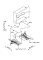
図2は、本実施形態のパンツ型の吸収性物品の一例としてのパンツ型の使い捨ておむつ1の概略斜視図である。図3Aは、展開状態のおむつ1を肌側から見た概略平面図であり、図3Bは、図3A中のB-B矢視の概略図である。図4は、展開状態のおむつ1を分解して示す概略斜視図である。図5は、展開状態の外装シート11を非肌側から見た概略平面図である。
図2は、本実施形態のパンツ型の吸収性物品の一例としてのパンツ型の使い捨ておむつ1の概略斜視図である。図3Aは、展開状態のおむつ1を肌側から見た概略平面図であり、図3Bは、図3A中のB-B矢視の概略図である。図4は、展開状態のおむつ1を分解して示す概略斜視図である。図5は、展開状態の外装シート11を非肌側から見た概略平面図である。
なお、以下の説明では、おむつ1が着用者に装着された際に、当該着用者の肌側に位置すべき側のことを単に「肌側」と言い、他方、着用者の非肌側に位置すべき側のことを単に「非肌側」と言う。
図3Aに示すように、このおむつ1は、例えば2ピースタイプのおむつ1である。すなわち、同おむつ1は、尿などの排泄液を吸収する例えば平面視略長方形形状の吸収性本体3を第1部品として有し、そして、上記吸収性本体3の非肌側面を覆って設けられておむつ1の外装をなす平面視略砂時計形状の外装シート11を第2部品として有している。
図3A、図3B、及び図4に示すように、吸収性本体3は、排泄液を吸収する吸収性コア3cを有する。吸収性コア3cは、パルプ繊維等の液体吸収性繊維や高吸収性ポリマー等の液体吸収性粒状物を、所定形状の一例としての平面視略砂時計形状に成形したものである。なお、かかる吸収性コア3cは、必要に応じてティッシュペーパー等の液透過性の被覆シートで被覆されていても良い。
かかる吸収性コア3cの肌側面には、当該面を全面に亘って覆うように不織布等の液透過性のトップシート4が設けられており、同様に、同吸収性コア3cの非肌側面には、当該面を全面に亘って覆うようにフィルム等の液不透過性の防漏シート5が設けられている。ここで、この例では、どちらのシート4,5も、平面視略長方形形状に形成されており、また、どちらのシート4,5も、吸収性コア3cの外形輪郭から全周に亘って外方に飛び出している。そして、トップシート4において飛び出した部分と防漏シート5において飛び出した部分とが、互いに接着や溶着等によって接合されており、その結果、平面視略長方形形状の吸収性本体3が形成されている。
なお、不図示であるが、かかる吸収性本体3の幅方向の両端部に対して、それぞれ、同本体3の長手方向に沿って弾性部材としての糸ゴムを設けても良い。かかる糸ゴムは、吸収性本体3及び外装シート11における脚回り開口部1HLの近傍部分に伸縮性を付与するものである。よって、かかる糸ゴムは、トップシート4と防漏シート5との間に介挿されつつ、自然長から2~4倍等の所定倍率まで伸長された状態でホットメルト接着剤等の接着剤により両シート4,5に固定される。
また、場合によっては、尿の横漏れを防止する目的で防漏壁部(不図示)を吸収性本体3に設けても良い。かかる防漏壁部は、立体ギャザーとも呼ばれるものであり、不織布等の柔軟なシートを材料として、吸収性本体3の肌側面等の両端部にそれぞれ起立するように設けられる。但し、かかる防漏壁部は、周知構成である。そのため、これ以上の説明については省略する。
外装シート11は、図5の展開状態においては、平面視略砂時計形状の柔軟なシートであり、同シート11は、互いに直交する三方向として、厚さ方向と長手方向と幅方向とを有している。また、当該外装シート11は、長手方向に関して三つの部分11a,11b,11cに区分される。すなわち、外装シート11は、着用者の腹側に配される腹側部11aと、着用者の背側に配される背側部11bと、着用者の股間に配される股下部11cとに区分される。なお、当然ながら、股下部11cは、腹側部11aと背側部11bとの間に位置しており、これにより、当該股下部11cは、平面視略砂時計形状において幅方向に括れた形状の部分11cとなっている。
図4に示すように、かかる外装シート11は、一枚のシート12を本体とするか、或いは複数枚のシートを積層一体化した積層シートを本体とし、この例では、一枚のシート12を本体としている。なお、この本体となるシート12の材料には、熱可塑性樹脂繊維を含む不織布や熱可塑性樹脂フィルム等が使用され、この例では、15(g/m2)の坪量のSMS不織布(スパンボンド/メルトブローン/スパンボンド不織布)が使用されているが、何等これに限らない。
また、図4及び図5に示すように、この例では、同シート12における腹側部12a及び背側部12bに対しては、それぞれ、当該シート12の非肌側面に別のシート13a,13bが接着又は溶着等によって接合されているが、股下部12cについては、別のシートが接合されていない。但し、何等これに限らず、股下部12cにも別のシートが接合されていても良く、更には、股下部12cの別のシートが、腹側部12aの別のシート13a及び背側部12bの別のシート13bと一体であっても良い。また、当該別のシート13a,13bの材料には、熱可塑性樹脂繊維を含む不織布や熱可塑性樹脂フィルム等が使用され、この例では、熱可塑性樹脂繊維を含む17(g/m2)の坪量のスパンボンド不織布が使用されているが、何等これに限らない。
なお、以下では、外装シート11の本体となる上記シート12のことを「本体シート12」と言い、本体シート12における腹側部12aに接合される上記別のシート13aのことを「腹側部外面シート13a」と言い、本体シート12における背側部12bに接合される上記別シート13bのことを「背側部外面シート13b」という。
ここで、図4及び図5に示すように、本体シート12と腹側部外面シート13aとの間、及び本体シート12と背側部外面シート13bとの間には、それぞれ、弾性部材の一例としての糸ゴム15,15…が介挿されている。かかる糸ゴム15,15…は、外装シート11の腹側部11a及び背側部11bに対して幅方向の伸縮性を付与するものである。そのため、当該糸ゴム15,15…は、自然長から2~4倍等の所定倍率まで伸長された状態で幅方向に沿って配置されつつ、ホットメルト接着剤等の接着剤により展開状態の各シート12,13a,13bに固定されている。かかる糸ゴム15,15…は、本体シート12の長手方向に並んで互いの間に間隔をあけながら複数本配置されており、これにより、腹側部11a及び背側部11bのそれぞれについて上記長手方向の広範囲に亘って伸縮性が付与されている。
また、図4に示すように、腹側部外面シート13a及び背側部外面シート13bは、それぞれ本体シート12における長手方向の端縁部12eLa,12eLbよりも外方に飛び出すように設けられており、そして、各シート13a,13bにおいて本体シート12から外方に飛び出した部分13ap,13bpについては、長手方向の内方に折り返されていて、これにより、図3Bに示すように、当該飛び出した部分13ap,13bpは、本体シート12の肌側面に重ね合わせられている。そして、これにより、胴回り開口部1HBとなる端縁部11HBa,11HBbは、腹側部外面シート13aの折り返し部13ak及び背側部外面シート13bの折り返し部13bkによって形成されていて、つまり、当該折り返し部13ak,13bkによって、本体シート12の端縁部12eLa,12eLbは覆われている。よって、本体シート12の端縁部12eLa,12eLbによって着用者の肌が傷つけられることは防止されている。なお、この例では、図3A及び図3Bを参照して明らかなように、本体シート12の肌側面に重ね合わせられた上記の飛び出した部分13ap,13bpは、更に吸収性本体3の長手方向の各端部3ea,3ebも肌側から覆っているが、何等これに限るものではない。すなわち、覆わなくても良い。
図3A及び図4に示すように、かかる外装シート11の肌側面、すなわち本体シート12の肌側面における幅方向の中央位置には、前述の吸収性本体3が互いの長手方向を揃えた状態で固定されている。また、吸収性本体3の長手方向の長さ及び幅方向の長さは、それぞれ、当該吸収性本体3が外装シート11の内側に概ね収まるような長さとされている。
そして、図3Aの如く吸収性本体3が固定された外装シート11は、股下部11cにて二つ折りされて腹側部11aと背側部11bとが重ね合わせられる。そして、この重ね合わせられた状態において、腹側部11aと背側部11bとが幅方向の各端部でそれぞれ接合されることにより、図2に示すような胴回り開口部1HBと一対の脚回り開口部1HL,1HLとが形成されたパンツ型のおむつ1の形態にされる。
なお、以下では、同図2の如くパンツ型にされたおむつ1の三次元形状の方向について、以下のように定義する。先ず、外装シート11の幅方向と平行な方向のことを「横方向」と言う。また、外装シート11の長手方向と平行な方向のことを「縦方向」と言う。横方向と縦方向とは直交している。また、横方向と縦方向との両者と直交する方向のことを「前後方向」と言う。なお、前後方向の前方が、着用者の前側たる腹側であり、同前後方向の後方が、着用者の後側たる背側である。また、おむつ1を装着した際には、上記の縦方向は上下方向を向くことから、縦方向のことを「上下方向」とも言う。ちなみに、上下方向で言えば、脚回り開口部1HLは、胴回り開口部1HBよりも下方に位置している。更に、横方向のことを「左右方向」とも言う。
上述の接合は、超音波溶着処理やヒートシール処理などで行われ、この例では、超音波溶着処理でなされている。そして、かかる接合に伴って、外装シート11の腹側部11aにおける横方向の各端部には、それぞれ接合部jが縦方向に沿って形成されており、同様に外装シート11の背側部11bにおける横方向の各端部にも、それぞれ接合部jが縦方向に沿って形成されている(図2)。なお、これら腹側部11aの接合部jと背側部11bの接合部jとは一体となっていて、上記の端部において表裏の位置関係にある謂わば同じものである。そのため、以下の説明では、区別しない。
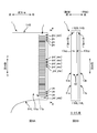
図6Aは、接合部jの概略拡大図であり、図6Bは、図6A中のB―B矢視の概略図である。上述のように、接合部jは、縦方向に関しては、胴回り開口部1HBの方から脚回り開口部1HLの方へと延在している。詳しくは、接合部jは、前後方向(図6Aでは紙面を貫通する方向)にへこんで形成された複数の溶着部jm,jm…を縦方向に並んで有し、複数の溶着部jm,jm…は、所定の規則性を有した溶着パターンで形成されている。例えば、この例では、各溶着部jmは、それぞれ縦方向に隣り合う溶着部jmとの間に間隔をあけながら、横方向に長い略長方形に形成されている。
そして、本実施形態では、接合部jのうちで縦方向の最下方に位置する溶着部jm、すなわち、接合部jのうちで脚回り開口部1HLに最も近い溶着部jm(第1部分に相当し、以下では、溶着部jmbとも言う)の接合強度(N)を、縦方向の中央部に位置する複数の各溶着部jm(所定部分に相当し、以下では、溶着部jmcとも言う)の接合強度(N)よりも小さくしている。また、ここで言う「接合強度」とは、縦方向に沿って腹側部11aと背側部11bとを引き剥がす際に必要な外力の大きさ(N)のことである。
よって、かかるおむつ1によれば、縦方向の中央部に位置する複数の各溶着部jmc,jmc…の大きな接合強度に基づいて、接合部jの接合強度を全体としておむつ1の装着に耐え得る大きさに保ちながらも、縦方向の最下方に位置する溶着部jmbを起点として、比較的小さな外力でもって、腹側部11aと背側部11bとの接合を解くことができる。そして、その結果、脚回り開口部1HL側から腹側部11aと背側部11bとを速やか且つ容易に引き剥がすことができる。
よって、かかるおむつ1によれば、縦方向の中央部に位置する複数の各溶着部jmc,jmc…の大きな接合強度に基づいて、接合部jの接合強度を全体としておむつ1の装着に耐え得る大きさに保ちながらも、縦方向の最下方に位置する溶着部jmbを起点として、比較的小さな外力でもって、腹側部11aと背側部11bとの接合を解くことができる。そして、その結果、脚回り開口部1HL側から腹側部11aと背側部11bとを速やか且つ容易に引き剥がすことができる。
また、この例では、横方向たる左右の各端部にそれぞれ形成されたどちらの接合部j,j(図2)についても、図6Aに示すように縦方向の最下方に位置する溶着部jmbの接合強度が、縦方向の中央部に位置する複数の各溶着部jmc,jmc…の接合強度よりも小さくされている。よって、おむつ交換の作業者が、図2の左右二つの脚回り開口部1HL,1HLのうちのどちらの開口部1HLを選んだ場合でも、腹側部11aと背側部11bとを容易に引き剥がすことができて、これにより、当該作業者は、速やかにおむつ1を脱がすことができる。但し、何等これに限るものではない。すなわち、横方向たる左右の各端部のうちのどちらか一方の端部の接合部jだけが、上述のような仕様とされていても良い。
なお、溶着部jmbの接合強度(N)は、例えば溶着部jmcの接合強度(N)の5%~70%の値から選択され、望ましくは、同接合強度(N)の10%~50%の値から選択されると良く、より望ましくは、同接合強度(N)の20%~40%の値から選択されると良い。
また、最下方の溶着部jmbと接合強度(N)を対比すべき縦方向の中央部に位置する複数の各溶着部jmcの個数としては、例えば2ヶ~20ヶであっても良いし、或いは、5ヶ~15ヶであっても良い。更に言えば、上述では、最下方の溶着部jmbの接合強度(N)を、縦方向の中央部に位置する複数の各溶着部jmc,jmc…の接合強度(N)よりも小さくしていたが、何等これに限らない。例えば、場合によっては、接合部jが有する溶着部jm,jm…のうちで最下方の溶着部jmbを除く全て溶着部jm,jm…の接合強度(N)よりも、当該最下方の溶着部jmbの接合強度(N)を小さくしても良い。
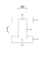
かかる接合部jにおける接合強度(N)の縦方向の分布は、例えば次のようにして測定することができる。先ず、接合部jを切断しないように注意しながら、おむつ1から外装シート11の横方向の端部を縦方向に長い帯状に切り離し、これにより、図7に示すような縦方向に長い帯状の測定用サンプルSを作成する。そして、同測定用サンプルSの縦方向の下端部に溶着部jmが形成されていない部分Njmが存在する場合には、当該溶着部jmが形成されていない部分Njmを腹側部11aと背側部11bとに分けて、これらを一対の摘みとして使用する。すなわち、一対の摘みのうちの一方の摘みを、不図示の引っ張り試験機(例えば、株式会社島津製作所製AUTOGRAPH(型式AG-1kNI))が具備する一方のヘッドにチャックし、他方の摘みを同試験機の他方のヘッドにチャックする。ここで、一方のヘッドは、試験機に移動不能に固定された固定ヘッドであり、他方のヘッドは、固定ヘッドの下方に同軸に設けられて上下方向に移動可能な移動ヘッドである。そして、固定ヘッドに設けられたロードセルによって同ヘッドに作用する引っ張り荷重値(N)を計測しながら、300(mm/分)の一定の移動速度値で移動ヘッドを固定ヘッドから下方に離間させていく。すると、これにより、測定用サンプルSの腹側部11aと背側部11bとが順次引き剥がされていき、つまり、引き剥がされる位置が、測定用サンプルSにおける下端部から上端部へと縦方向に順次移動していくが、当該位置が最終的に上端部に至ると、測定用サンプルSは腹側部11aと背側部11bとに完全に引き剥がされた分離状態となって、そうなれば、測定は終了する。
ちなみに、測定用サンプルSの縦方向の下端部の端まで溶着部jmが形成されている場合には、当該下端部に一対の摘みを形成し難いが、そのような場合には、測定用サンプルSの縦方向の上端部の幾つかの溶着部jm,jmを犠牲にしつつ同上端部に一対の摘みを形成し、これにより、当該上端部から下端部へと引き剥がすようにしても良い。
ところで、望ましくは、図6Aの接合部jのうちで縦方向の最上方に位置する溶着部jm、すなわち、接合部jのうちで胴回り開口部1HBに最も近い溶着部jm(第3部分に相当し、以下では、溶着部jmtとも言う)の接合強度(N)についても、縦方向の中央部に位置する複数の各溶着部jmc,jmc…の接合強度(N)よりも小さくしていると良い。
そして、このようにしていれば、何らかの事情で脚回り開口部1HLからの引き剥がしが困難な場合には、即座に胴回り開口部1HBからの引き剥がしに切り替えることができて、これにより、おむつ1を速やかに脱がすことができる。
なお、その場合に、脚回り開口部1HLに最も近い溶着部jmbの接合強度(N)と、胴周り開口部1HBに最も近い溶着部jmtの接合強度(N)との大小関係については、互いに同値にしても良いし、前者の方を小さくしても良い。ちなみに、前者の方を小さくすれば、脚回り開口部1HLから引き剥がし易くなる。
ところで、図6Aの例では、接合強度(N)を小さくすべき縮小対象の溶着部jmb(jmt)の面積(m2)を、縮小対象ではない溶着部jmcの面積(m2)よりも小さくすること、並びに、同縮小対象の溶着部jmb(jmt)の単位面積当たりの接合力(N/m2)を、縮小対象ではない溶着部jmcの単位面積当たりの接合力(N/m2)よりも小さくすることの両方によって、縮小対象の溶着部jmb(jmt)の接合強度(N)を、縮小対象ではない溶着部jmcの接合強度(N)よりも小さくしているが、何等これに限らない。すなわち、縮小対象の溶着部jmb(jmt)の接合強度(N)が、縮小対象ではない溶着部jmcの接合強度(N)よりも小さくなっていれば、何等上述に限らない。
例えば、縮小対象の溶着部jmb(jmt)の面積と、縮小対象ではない溶着部jmcの面積とを互いに同値にした場合には、縮小対象の溶着部jmb(jmt)の単位面積当たりの接合力(N/m2)を、縮小対象ではない溶着部jmcの単位面積当たりの接合力(N/m2)よりも小さくすることよって、縮小対象の溶着部jmb(jmt)の接合強度(N)を、縮小対象ではない溶着部jmcの接合強度(N)よりも小さくしても良い。或いは、縮小対象の溶着部jmb(jmt)の単位面積当たりの接合力(N/m2)と、縮小対象ではない溶着部jmcの単位面積当たりの接合力(N/m2)とを互いに同値にした場合には、縮小対象の溶着部jmb(jmt)の面積(m2)を、縮小対象ではない溶着部jmcの面積(m2)よりも小さくすることよって、縮小対象の溶着部jmb(jmt)の接合強度(N)を、縮小対象ではない溶着部jmcの接合強度(N)よりも小さくしても良い。
但し、この例のように、縮小対象の溶着部jmb(jmt)の面積(m2)を小さくするとともに、その単位面積当たりの接合力(N/m2)も小さくした方が、当該縮小対象の溶着部jmb(jmt)の接合強度(N)を確実に小さくすることができるため、好ましい。
また、場合によっては、胴周り開口部1HBでも腹側部11aと背側部11bとを円滑に引き剥がせないこともあり得る。そして、その場合には、おむつ交換の作業者は、外装シート11自体を破ることによっておむつ1を脱がすことになるが、この点につき、この例では、図6Bに示すように、前述の外装シート11に係る腹側部外面シート13a及び背側部外面シート13bの胴周り開口部1HBでの折り返しに起因して、外装シート11において脚回り開口部1HLをなす部分11HLの坪量(g/m2)の方が、同外装シート11において胴周り開口部1HBをなす部分11HBの坪量(g/m2)よりも小さくなっている。よって、おむつ交換の作業者は、脚回り開口部1HLから外装シート11自体を比較的容易に破ることができて、その結果、おむつ1の交換作業の停滞を防ぐことができる。
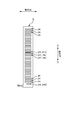
更に、この例では、図6Aのように脚回り開口部1HLに最も近い一つの溶着部jmbの接合強度(N)だけを小さくしていたが、この接合強度を小さくする対象の溶着部jmの数は、何等一つに限らず、複数にしても良い。例えば、図8に示すように、この脚回り開口部1HLに最も近い溶着部jmbを第1溶着部jmb(第1部分に相当)とした場合に、この第1溶着部jmbの胴回り開口部1HL側に隣り合う溶着部jm(第2部分に相当し、以下では、第2溶着部jmb2とも言う)の接合強度を、第1溶着部jmbと同じように、縦方向の中央部の複数の各溶着部jmc,jmc…よりも小さくしても良い。
更には、これら第1溶着部jmb及び第2溶着部jmb2の接合強度(N)を互いに同じ大きさに揃えても良いが、揃えなくても良い。例えば、第2溶着部jmb2の接合強度を、第1溶着部jmbの接合強度と、縦方向の中央部に位置する複数の各溶着部jmcの接合強度との間の大きさにしても良い。そして、このようにしていれば、脚回り開口部1HLの近傍に位置する少なくとも二つの溶着部jmb,jmb2については、接合強度が、脚回り開口部1HLに近い位置の溶着部jmほど小さくなっている。よって、腹側部11aと背側部11bとの引き剥がしを脚回り開口部1HLから円滑に行うことができる。
なお、脚回り開口部1HLの近傍の溶着部jmb,jmb2について述べた上記の内容は、胴回り開口部1HBの近傍に位置する溶着部jmについても同様である。すなわち、以前に図6Aを参照しながら、胴回り開口部1HBに最も近い一つの溶着部jmtの接合強度を小さくしても良いと述べたが、この接合強度を小さくする対象の溶着部jmの数は、何等一つに限らず、複数にしても良い。例えば、この胴回り開口部1HBに最も近い溶着部jmtを第3溶着部jmt(第3部分に相当)とした場合に、この第3溶着部jmtの脚回り開口部1HL側に隣り合う溶着部jm(第4部分に相当し、以下では、第4溶着部jmt4とも言う)の接合強度を、第3溶着部jmtと同じように小さくしても良い。
更には、これら第3溶着部jmt及び第4溶着部jmt4の接合強度(N)を互いに同じ大きさに揃えても良いが、揃えなくても良い。例えば、第4溶着部jmt4の接合強度を、第3溶着部jmtの接合強度と、縦方向の中央部に位置する複数の各溶着部jmcの接合強度との間の大きさにしても良い。そして、このようにしていれば、胴回り開口部1HBの近傍に位置する少なくとも二つの溶着部jmt,jmt4については、接合強度が、胴回り開口部1HBに近い位置の溶着部jmほど小さくなっている。よって、腹側部11aと背側部11bとの引き剥がしを胴回り開口部1HBから円滑に行うことができる。
このような溶着部jm,jm…を有した接合部jの形成は、適宜な不図示の超音波溶着装置によって実現される。超音波溶着装置は、超音波エネルギーを溶着対象部分に投入することによって、溶着対象部分を摩擦発熱して溶着する。そして、溶着した部分が溶着部jm,jm…として外装シート11上に残存する。
かかる超音波溶着装置は、例えば、上記の縦方向に対応する方向(以下、CD方向とも言う)に延びたレール状のホーンを有する。ホーンは、超音波振動を行う発振面を有する。発振面は、CD方向に延びた帯状平面をなしており、その法線方向に20~35kHz等の所定周波数で超音波振動する。また、同装置は、ホーンの上記帯状平面をCD方向に転がり可能なローラー状のアンビル(以下、アンビルローラーと言う)を有している。アンビルローラーの外周面には、前述の溶着部jm,jm…の形成パターンに対応させて複数の突部が設けられている。そして、パンツ型にすべく二つ折り状態された外装シート11の縦方向がCD方向に揃うように、外装シート11がホーンの発振面たる帯状平面上に載置されるとともに、ホーンが超音波振動をしている間に、アンビルローラーがCD方向に沿って外装シート11を横断することによって、接合部jとして複数の溶着部jm,jm…が外装シート11に形成されるが、ここで、この横断時には、CD方向に単位長さ当たりに投入される超音波エネルギー(J/m)が、外装シート11のうちで脚回り開口部1HLに最も近い部分で小さくなるように調整される。そして、これにより、脚回り開口部1HLに最も近い溶着部jmbの接合強度(N)が選択的に小さくされる。なお、超音波エネルギー(J/m)の大きさを変更する方法としては、超音波振動の振幅を変更すること、ホーンへのアンビルローラーの押し付け力を変更すること、ホーンとアンビルローラーとの間の間隔を変更すること等を例示することができる。
かかる超音波溶着装置は、例えば、上記の縦方向に対応する方向(以下、CD方向とも言う)に延びたレール状のホーンを有する。ホーンは、超音波振動を行う発振面を有する。発振面は、CD方向に延びた帯状平面をなしており、その法線方向に20~35kHz等の所定周波数で超音波振動する。また、同装置は、ホーンの上記帯状平面をCD方向に転がり可能なローラー状のアンビル(以下、アンビルローラーと言う)を有している。アンビルローラーの外周面には、前述の溶着部jm,jm…の形成パターンに対応させて複数の突部が設けられている。そして、パンツ型にすべく二つ折り状態された外装シート11の縦方向がCD方向に揃うように、外装シート11がホーンの発振面たる帯状平面上に載置されるとともに、ホーンが超音波振動をしている間に、アンビルローラーがCD方向に沿って外装シート11を横断することによって、接合部jとして複数の溶着部jm,jm…が外装シート11に形成されるが、ここで、この横断時には、CD方向に単位長さ当たりに投入される超音波エネルギー(J/m)が、外装シート11のうちで脚回り開口部1HLに最も近い部分で小さくなるように調整される。そして、これにより、脚回り開口部1HLに最も近い溶着部jmbの接合強度(N)が選択的に小さくされる。なお、超音波エネルギー(J/m)の大きさを変更する方法としては、超音波振動の振幅を変更すること、ホーンへのアンビルローラーの押し付け力を変更すること、ホーンとアンビルローラーとの間の間隔を変更すること等を例示することができる。
===その他の実施の形態===
以上、本発明の実施形態について説明したが、上記の実施形態は、本発明の理解を容易にするためのものであり、本発明を限定して解釈するためのものではない。また、本発明は、その趣旨を逸脱することなく、変更や改良され得るとともに、本発明にはその等価物が含まれるのはいうまでもない。例えば、以下に示すような変形が可能である。
以上、本発明の実施形態について説明したが、上記の実施形態は、本発明の理解を容易にするためのものであり、本発明を限定して解釈するためのものではない。また、本発明は、その趣旨を逸脱することなく、変更や改良され得るとともに、本発明にはその等価物が含まれるのはいうまでもない。例えば、以下に示すような変形が可能である。
上述の実施形態では、図2の接合部jが有する複数の溶着部jm,jm…の一例として、図6Aに示すように横方向に長い略長方形の溶着部jmを例示したが、溶着部jmの形状は何等これに限らない。例えば、楕円形でも良いし円形でも良い。また、複数の溶着部jm,jm…が全体として形作る溶着パターンについても、何等上述したような溶着部jm,jm…が縦方向に並んでなる単純な縦並びパターンに限らない。例えば、円形の溶着部が格子状に並んでなる格子状パターンであっても良いし、或いは、溶着部が接合部jにおける縦方向の略全長に亘って帯状に連続してなるベタ状パターンであっても良いし、これら以外のパターンでも良い。
上述の実施形態では、第1部品としての吸収性本体3を非肌側から第2部品としての平面視略砂時計形状の外装シート11で覆ってなる2ピースタイプのおむつ1を例示したが、何等これに限らない。例えば、本発明に係る前述の接合部jを、所謂3ピースタイプのおむつに対して形成しても良い。詳しくは次の通りである。
先ず、図9に示すように、同おむつは、第1部品として着用者の股間に配される吸収性本体3を有し、第2部品として同着用者の腹側に配される腹側帯部材21aを有し、第3部品として同着用者の背側に配される背側帯部材21bを有している。また、図9の展開状態では、腹側帯部材21aと背側帯部材21bとが互いの間に間隔をあけて平行に並んだ状態で、これらの間に吸収性本体3が掛け渡されつつ、同吸収性本体3の長手方向の各端部3ea,3ebがそれぞれ最寄りの帯部材21a,21bに接合固定されており、その外観形状は平面視略H形状をなしている。そして、この展開状態から、吸収性本体3が長手方向の略中央部で二つ折りされるとともに、この二つ折りの状態において互いに重ね合わせられる帯部材21a,21b同士が、上記長手方向と直交する幅方向(横方向に相当)の各端部にて接合されると、これら帯部材21a,21b同士が環状に繋がって、これにより、胴周り開口部及び一対の脚周り開口部が形成されたおむつとなる。そして、かかる接合に対しても、前述の接合部jを適用可能である。なお、各帯部材21a,21bは、熱可塑性樹脂繊維を含む不織布等の柔軟なシートを材料として形成される。また、吸収性本体3の構成は、前述したものと概ね同じであるので、その説明については省略する。
先ず、図9に示すように、同おむつは、第1部品として着用者の股間に配される吸収性本体3を有し、第2部品として同着用者の腹側に配される腹側帯部材21aを有し、第3部品として同着用者の背側に配される背側帯部材21bを有している。また、図9の展開状態では、腹側帯部材21aと背側帯部材21bとが互いの間に間隔をあけて平行に並んだ状態で、これらの間に吸収性本体3が掛け渡されつつ、同吸収性本体3の長手方向の各端部3ea,3ebがそれぞれ最寄りの帯部材21a,21bに接合固定されており、その外観形状は平面視略H形状をなしている。そして、この展開状態から、吸収性本体3が長手方向の略中央部で二つ折りされるとともに、この二つ折りの状態において互いに重ね合わせられる帯部材21a,21b同士が、上記長手方向と直交する幅方向(横方向に相当)の各端部にて接合されると、これら帯部材21a,21b同士が環状に繋がって、これにより、胴周り開口部及び一対の脚周り開口部が形成されたおむつとなる。そして、かかる接合に対しても、前述の接合部jを適用可能である。なお、各帯部材21a,21bは、熱可塑性樹脂繊維を含む不織布等の柔軟なシートを材料として形成される。また、吸収性本体3の構成は、前述したものと概ね同じであるので、その説明については省略する。
1 おむつ(吸収性物品)、1HB 胴回り開口部、1HL 脚回り開口部、
3 吸収性本体、3ea 端部、3eb 端部、
3c 吸収性コア、4 トップシート、5 防漏シート、
11 外装シート、11HB 胴回り開口部をなす部分、
11HBa 胴回り開口部となる端縁部、11HBb 胴回り開口部となる端縁部、
11HL 脚回り開口部をなす部分、
11a 腹側部、11b 背側部、11c 股下部、
12 本体シート、12a 腹側部、12b 背側部、12c 股下部、
12eLa 端縁部、12eLb 端縁部、
13a 腹側部外面シート、13ak 折り返し部、13ap 飛び出した部分、
13b 背側部外面シート、13bk 折り返し部、13bp 飛び出した部分、
15 糸ゴム(弾性部材)、
21a 腹側帯部材、21b 背側帯部材、
j 接合部、jm 溶着部、
jmb 第1溶着部(第1部分)、jmb2 第2溶着部(第2部分)、
jmc 溶着部(所定部分)、
jmt 第3溶着部(第3部分)、jmt4 第4溶着部(第4部分)、
Njm 部分、
S 測定用サンプル、
Claims (7)
- 装着時に着用者の腹側に配される腹側部と、前記着用者の背側に配される背側部と、前記着用者の股間に配される股下部とを有した吸収性物品を、前記股下部にて二つ折りして前記腹側部と前記背側部とを重ね合わせた状態で、前記腹側部と前記背側部とを横方向の各端部でそれぞれ接合することにより、胴回り開口部と一対の脚回り開口部とが形成されたパンツ型の吸収性物品であって、
前記腹側部と前記背側部とを接合するために前記横方向の前記各端部に形成された各接合部は、それぞれ、前記胴回り開口部の方から前記脚回り開口部の方へと延在しており、
前記各接合部のうちの少なくとも一方の接合部のうちで前記脚回り開口部に最も近い第1部分の接合強度は、前記接合部のうちで前記第1部分と前記胴回り開口部との間に位置する所定部分の接合強度よりも小さいことを特徴とするパンツ型の吸収性物品。 - 請求項1に記載のパンツ型の吸収性物品であって、
前記接合部は、前記第1部分の前記胴回り開口部側に隣り合う第2部分を有し、
前記第2部分の接合強度は、前記第1部分の接合強度と前記所定部分の接合強度との間の大きさであることを特徴とするパンツ型の吸収性物品。 - 請求項1又は2に記載のパンツ型の吸収性物品であって、
前記接合部のうちで前記胴回り開口部に最も近い第3部分の接合強度は、前記所定部分の接合強度よりも小さいことを特徴とするパンツ型の吸収性物品。 - 請求項3に記載のパンツ型の吸収性物品であって、
前記接合部は、前記第3部分の前記脚回り開口部側に隣り合う第4部分を有し、
前記第4部分の接合強度は、前記第3部分の接合強度と前記所定部分の接合強度との間の大きさであることを特徴とするパンツ型の吸収性物品。 - 請求項1乃至4の何れかに記載のパンツ型の吸収性物品であって、
前記第1部分の接合強度は、前記第3部分の接合強度よりも小さいことを特徴とするパンツ型の吸収性物品。 - 請求項1乃至5の何れかに記載のパンツ型の吸収性物品であって、
前記腹側部及び前記背側部において前記脚回り開口部をなす部分の坪量(g/m2)は、前記腹側部及び前記背側部において前記胴回り開口部をなす部分の坪量(g/m2)よりも小さいことを特徴とするパンツ型の吸収性物品。 - 請求項1乃至6の何れかに記載のパンツ型の吸収性物品であって、
前記各接合部のうちのどちらの接合部も、それぞれ、前記第1部分と前記所定部分とを有していることを特徴とするパンツ型の吸収性物品。
Applications Claiming Priority (2)
| Application Number | Priority Date | Filing Date | Title |
|---|---|---|---|
| JP2014021103A JP6255266B2 (ja) | 2014-02-06 | 2014-02-06 | パンツ型の吸収性物品 |
| JP2014-021103 | 2014-09-24 |
Publications (1)
| Publication Number | Publication Date |
|---|---|
| WO2015118735A1 true WO2015118735A1 (ja) | 2015-08-13 |
Family
ID=53777554
Family Applications (1)
| Application Number | Title | Priority Date | Filing Date |
|---|---|---|---|
| PCT/JP2014/078772 Ceased WO2015118735A1 (ja) | 2014-02-06 | 2014-10-29 | パンツ型の吸収性物品 |
Country Status (2)
| Country | Link |
|---|---|
| JP (1) | JP6255266B2 (ja) |
| WO (1) | WO2015118735A1 (ja) |
Cited By (1)
| Publication number | Priority date | Publication date | Assignee | Title |
|---|---|---|---|---|
| CN110730650A (zh) * | 2017-06-05 | 2020-01-24 | 尤妮佳股份有限公司 | 吸收性物品 |
Families Citing this family (6)
| Publication number | Priority date | Publication date | Assignee | Title |
|---|---|---|---|---|
| JP6745844B2 (ja) * | 2018-06-29 | 2020-08-26 | ユニ・チャーム株式会社 | 吸収性物品 |
| JP7321974B2 (ja) * | 2020-05-28 | 2023-08-07 | ユニ・チャーム株式会社 | パンツ型吸収性物品 |
| JP7641830B2 (ja) * | 2021-06-17 | 2025-03-07 | 大王製紙株式会社 | パンツタイプ使い捨て着用物品 |
| JP7350946B2 (ja) * | 2021-08-19 | 2023-09-26 | 花王株式会社 | パンツ型吸収性物品 |
| JP7338026B2 (ja) * | 2021-12-27 | 2023-09-04 | 花王株式会社 | パンツ型吸収性物品 |
| WO2023127768A1 (ja) * | 2021-12-27 | 2023-07-06 | 花王株式会社 | パンツ型吸収性物品 |
Citations (6)
| Publication number | Priority date | Publication date | Assignee | Title |
|---|---|---|---|---|
| JPH0631721U (ja) * | 1992-10-08 | 1994-04-26 | トーヨー衛材株式会社 | パンツ型使い捨ておむつ |
| JPH10137288A (ja) * | 1996-11-15 | 1998-05-26 | Kao Corp | パンツ型使い捨ておむつ |
| JP2003038573A (ja) * | 2001-08-03 | 2003-02-12 | Oji Paper Co Ltd | パンツ型使い捨ておむつ |
| JP2009131539A (ja) * | 2007-11-30 | 2009-06-18 | Daio Paper Corp | パンツ型使い捨ておむつ |
| JP2011072577A (ja) * | 2009-09-30 | 2011-04-14 | Daio Paper Corp | 吸収性物品 |
| JP2013169312A (ja) * | 2012-02-21 | 2013-09-02 | Oji Nepia Co Ltd | パンツ型使い捨ておむつ |
-
2014
- 2014-02-06 JP JP2014021103A patent/JP6255266B2/ja active Active
- 2014-10-29 WO PCT/JP2014/078772 patent/WO2015118735A1/ja not_active Ceased
Patent Citations (6)
| Publication number | Priority date | Publication date | Assignee | Title |
|---|---|---|---|---|
| JPH0631721U (ja) * | 1992-10-08 | 1994-04-26 | トーヨー衛材株式会社 | パンツ型使い捨ておむつ |
| JPH10137288A (ja) * | 1996-11-15 | 1998-05-26 | Kao Corp | パンツ型使い捨ておむつ |
| JP2003038573A (ja) * | 2001-08-03 | 2003-02-12 | Oji Paper Co Ltd | パンツ型使い捨ておむつ |
| JP2009131539A (ja) * | 2007-11-30 | 2009-06-18 | Daio Paper Corp | パンツ型使い捨ておむつ |
| JP2011072577A (ja) * | 2009-09-30 | 2011-04-14 | Daio Paper Corp | 吸収性物品 |
| JP2013169312A (ja) * | 2012-02-21 | 2013-09-02 | Oji Nepia Co Ltd | パンツ型使い捨ておむつ |
Cited By (3)
| Publication number | Priority date | Publication date | Assignee | Title |
|---|---|---|---|---|
| CN110730650A (zh) * | 2017-06-05 | 2020-01-24 | 尤妮佳股份有限公司 | 吸收性物品 |
| EP3622928A4 (en) * | 2017-06-05 | 2020-05-27 | Unicharm Corporation | ABSORBENT ARTICLE |
| CN110730650B (zh) * | 2017-06-05 | 2021-11-26 | 尤妮佳股份有限公司 | 吸收性物品 |
Also Published As
| Publication number | Publication date |
|---|---|
| JP6255266B2 (ja) | 2017-12-27 |
| JP2015146887A (ja) | 2015-08-20 |
Similar Documents
| Publication | Publication Date | Title |
|---|---|---|
| JP6255266B2 (ja) | パンツ型の吸収性物品 | |
| JP6171120B1 (ja) | 吸収性物品に係るシート状部材の製造方法、及び製造装置 | |
| JP4261420B2 (ja) | 使い捨ておむつ | |
| JP5238567B2 (ja) | パンツ型吸収性物品 | |
| JP2011234847A (ja) | パンツ型吸収性物品 | |
| JP2013208358A (ja) | 使い捨て着用物品 | |
| WO2015166671A1 (ja) | パンツ型の吸収性物品 | |
| JP2017104197A (ja) | パンツ型吸収性物品 | |
| KR102208903B1 (ko) | 풀온 착용 물품 | |
| JP2010213924A (ja) | 使い捨ておむつ | |
| JP2017060788A (ja) | 使い捨て着用物品 | |
| JP2011139857A5 (ja) | ||
| JPWO2019123549A1 (ja) | パンツ型着用物品 | |
| JP5836329B2 (ja) | 吸収性物品 | |
| JP2018088945A (ja) | パンツ型着用物品 | |
| JP6296761B2 (ja) | 使い捨て着用物品 | |
| JP5530196B2 (ja) | 使い捨てのパンツ型着用物品 | |
| JP4249097B2 (ja) | パンツ型使い捨ておむつ | |
| JP2018082865A (ja) | 使い捨ておむつ | |
| JP2013031535A (ja) | 使い捨て着用物品 | |
| JP2008161207A (ja) | 使い捨てのパンツ型着用物品 | |
| JP6255270B2 (ja) | パンツ型の吸収性物品 | |
| JP2014004493A (ja) | 使い捨ておむつ | |
| JP5550470B2 (ja) | 着用物品 | |
| JP2016002391A (ja) | パンツ型吸収性物品 |
Legal Events
| Date | Code | Title | Description |
|---|---|---|---|
| 121 | Ep: the epo has been informed by wipo that ep was designated in this application |
Ref document number: 14882080 Country of ref document: EP Kind code of ref document: A1 |
|
| NENP | Non-entry into the national phase |
Ref country code: DE |
|
| 122 | Ep: pct application non-entry in european phase |
Ref document number: 14882080 Country of ref document: EP Kind code of ref document: A1 |