WO2015115447A1 - タッチパネル装置及びタッチパネル制御方法 - Google Patents
タッチパネル装置及びタッチパネル制御方法 Download PDFInfo
- Publication number
- WO2015115447A1 WO2015115447A1 PCT/JP2015/052249 JP2015052249W WO2015115447A1 WO 2015115447 A1 WO2015115447 A1 WO 2015115447A1 JP 2015052249 W JP2015052249 W JP 2015052249W WO 2015115447 A1 WO2015115447 A1 WO 2015115447A1
- Authority
- WO
- WIPO (PCT)
- Prior art keywords
- parameter
- touch panel
- tactile sensation
- piezoelectric elements
- value
- Prior art date
- Legal status (The legal status is an assumption and is not a legal conclusion. Google has not performed a legal analysis and makes no representation as to the accuracy of the status listed.)
- Ceased
Links
Images





Classifications
-
- G—PHYSICS
- G06—COMPUTING OR CALCULATING; COUNTING
- G06F—ELECTRIC DIGITAL DATA PROCESSING
- G06F3/00—Input arrangements for transferring data to be processed into a form capable of being handled by the computer; Output arrangements for transferring data from processing unit to output unit, e.g. interface arrangements
- G06F3/01—Input arrangements or combined input and output arrangements for interaction between user and computer
- G06F3/03—Arrangements for converting the position or the displacement of a member into a coded form
- G06F3/041—Digitisers, e.g. for touch screens or touch pads, characterised by the transducing means
- G06F3/0414—Digitisers, e.g. for touch screens or touch pads, characterised by the transducing means using force sensing means to determine a position
-
- G—PHYSICS
- G06—COMPUTING OR CALCULATING; COUNTING
- G06F—ELECTRIC DIGITAL DATA PROCESSING
- G06F3/00—Input arrangements for transferring data to be processed into a form capable of being handled by the computer; Output arrangements for transferring data from processing unit to output unit, e.g. interface arrangements
- G06F3/01—Input arrangements or combined input and output arrangements for interaction between user and computer
- G06F3/016—Input arrangements with force or tactile feedback as computer generated output to the user
-
- G—PHYSICS
- G06—COMPUTING OR CALCULATING; COUNTING
- G06F—ELECTRIC DIGITAL DATA PROCESSING
- G06F3/00—Input arrangements for transferring data to be processed into a form capable of being handled by the computer; Output arrangements for transferring data from processing unit to output unit, e.g. interface arrangements
- G06F3/01—Input arrangements or combined input and output arrangements for interaction between user and computer
- G06F3/03—Arrangements for converting the position or the displacement of a member into a coded form
- G06F3/041—Digitisers, e.g. for touch screens or touch pads, characterised by the transducing means
- G06F3/0416—Control or interface arrangements specially adapted for digitisers
-
- G—PHYSICS
- G06—COMPUTING OR CALCULATING; COUNTING
- G06F—ELECTRIC DIGITAL DATA PROCESSING
- G06F3/00—Input arrangements for transferring data to be processed into a form capable of being handled by the computer; Output arrangements for transferring data from processing unit to output unit, e.g. interface arrangements
- G06F3/01—Input arrangements or combined input and output arrangements for interaction between user and computer
- G06F3/048—Interaction techniques based on graphical user interfaces [GUI]
- G06F3/0487—Interaction techniques based on graphical user interfaces [GUI] using specific features provided by the input device, e.g. functions controlled by the rotation of a mouse with dual sensing arrangements, or of the nature of the input device, e.g. tap gestures based on pressure sensed by a digitiser
- G06F3/0488—Interaction techniques based on graphical user interfaces [GUI] using specific features provided by the input device, e.g. functions controlled by the rotation of a mouse with dual sensing arrangements, or of the nature of the input device, e.g. tap gestures based on pressure sensed by a digitiser using a touch-screen or digitiser, e.g. input of commands through traced gestures
-
- H—ELECTRICITY
- H04—ELECTRIC COMMUNICATION TECHNIQUE
- H04N—PICTORIAL COMMUNICATION, e.g. TELEVISION
- H04N1/00—Scanning, transmission or reproduction of documents or the like, e.g. facsimile transmission; Details thereof
- H04N1/0035—User-machine interface; Control console
- H04N1/00352—Input means
- H04N1/00392—Other manual input means, e.g. digitisers or writing tablets
-
- G—PHYSICS
- G06—COMPUTING OR CALCULATING; COUNTING
- G06F—ELECTRIC DIGITAL DATA PROCESSING
- G06F2203/00—Indexing scheme relating to G06F3/00 - G06F3/048
- G06F2203/01—Indexing scheme relating to G06F3/01
- G06F2203/014—Force feedback applied to GUI
Definitions
- the present invention relates to a touch panel device having a touch panel installed on a display unit and a touch panel control method, and more particularly to a touch panel device and a touch panel control method having a function of vibrating the touch panel and feeding back a tactile sensation to a user.
- touch panel devices in which a touch panel is installed on a display unit have become widespread.
- the touch panel device when it is detected that an operation key displayed on the display unit is touched via the touch panel, processing according to the touched operation key is performed.
- a piezoelectric element is provided on the touch panel, and when the user touches the operation surface of the touch panel, the touch panel is vibrated by applying a drive signal to the piezoelectric element. Feedback of tactile sensation is performed (see, for example, Patent Documents 1 to 3).
- This invention is made
- the touch panel device of the present invention is a touch panel device that includes a touch panel that is disposed on the display surface of the display unit and receives an operation, and a plurality of piezoelectric elements that vibrate the touch panel, a parameter value of a set first parameter, and a first parameter value.
- a vibration control unit that drives the plurality of piezoelectric elements, a first parameter table that stores a plurality of parameter values of the first parameter, A second parameter table storing a plurality of parameter values of two parameters, a third parameter table storing a plurality of parameter values of the third parameter, the plurality of parameter values of the first parameter, and the second parameter A plurality of parameter values and previous A tactile sensation pattern table storing a plurality of tactile sensation pattern values in combination with the plurality of parameter values of a third parameter, and a parameter value of the first parameter based on a plurality of tactile sensation pattern values stored in the tactile sensation pattern table.
- the touch panel control method of the present invention is a touch panel control method executed by a touch panel device that is arranged on a display surface of a display unit and receives an operation, and a plurality of piezoelectric elements that vibrate the touch panel.
- the plurality of piezoelectric elements are driven based on the parameter value of the first parameter, the parameter value of the second parameter, and the parameter value of the third parameter, and a plurality of parameter values of the first parameter are stored.
- the second parameter Based on a plurality of tactile sensation pattern values stored in the tactile sensation pattern table, and a plurality of tactile sensation pattern values stored by combining a plurality of parameter values and the plurality of parameter values of the third parameter.
- the parameter value of the first parameter, the parameter value of the second parameter, and the parameter value of the third parameter are set.
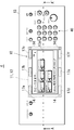
- FIG. 1 is a schematic cross-sectional view of an image forming apparatus according to the present invention. It is a top view which shows the structural example of the touchscreen apparatus shown in FIG.
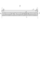
- FIG. 3 is a cross-sectional view taken along line A-A ′ shown in FIG. 2.
- FIG. 2 is a block diagram illustrating a schematic configuration of the image forming apparatus illustrated in FIG. 1. It is a figure which shows the setting reference
- the image forming apparatus 100 on which the touch panel device 10 according to the present embodiment is mounted is a copying machine, and includes a document reading unit 120, a document feeding unit 130, and a recording unit 140, as shown in FIG. .
- the document reading unit 120 is disposed above the recording unit 140
- the document feeding unit 130 is disposed above the document reading unit 120.
- the image forming apparatus 100 of the present embodiment has been described with reference to a copying machine, it is needless to say that a scanner, a multifunction peripheral, and the like are included.
- an operation unit 4 for setting and operating instructions of the image forming apparatus 100 is disposed on the front side of the image forming apparatus 100.
- the operation unit 4 is provided with a touch panel device 10 and operation buttons 40.
- the touch panel device 10 using the touch panel 12 will be described as an example of the operation panel.
- the operation panel device is not limited to the touch panel, and may be an operation panel device having an operation panel that does not have a substantial pushing stroke.
- the touch panel device 10 is provided on a display unit 11 that displays various operation keys that accept operation inputs, and a display surface of the display unit 11, and is touched by pressing an operator's fingertip, stylus, or the like.
- a touch panel 12 that receives an operation on an operation key displayed on the display unit 11 by detecting an input and outputting a signal corresponding to the position where the touch input is detected is provided.
- the display unit 11 and the touch panel 12 have substantially the same shape, and are rectangles with short sides arranged in the vertical direction and long sides arranged in the horizontal direction.
- a liquid crystal display panel can be used.
- a resistance film method or a capacitance method can be used as the touch panel 12.
- the display unit 11 is housed and held in the housing 13, and the housing 13 is provided with an upper cover 13 a that covers the display 11 and the peripheral area of the touch panel 12.
- the touch panel 12 is held via a plurality of elastic members 14 provided at locations covered with the upper cover 13 a.
- the elastic member 14 is made of a resin such as rubber, and the upper surface of the elastic member 14 is a fixing surface for fixing the touch panel 12.
- the touch panel 12 is fixed by the adhesive material applied to the upper surface of the elastic member 14.
- piezoelectric elements 17a to 17f are attached to the back surface of the touch panel 12 where it is covered with the upper cover 13a.
- the piezoelectric elements 17a to 17f function as a vibration unit that vibrates the touch panel 12.
- the piezoelectric elements 17a to 17c and the piezoelectric elements 17d to 17f are arranged at locations where they face each other in the short side direction and are covered with the upper cover 13a.
- Opposing piezoelectric elements 17a and 17d, piezoelectric element 17b and piezoelectric element 17e, and piezoelectric element 17c and piezoelectric element 17f are arranged in pairs.
- a set of the piezoelectric elements 17a and 17d is referred to as a first set
- a set of the piezoelectric elements 17b and 17e is referred to as a second set
- a set of the piezoelectric elements 17c and 17f is referred to as a third set.
- the operation button 40 includes a numeric keypad for inputting a numerical value such as the number of prints, a reset key for inputting an instruction for initializing setting information, a copying operation being stopped, and an inputted numerical value being deleted. Operation keys such as a stop key for starting and a start key for inputting an output instruction for starting a printing operation are provided.
- the document reading unit 120 includes a scanner 121, a platen glass 122, and a document reading slit 123.
- the scanner 121 includes an LED, a CCD (Charge Coupled Device) sensor, and the like, and is configured to be movable in the conveyance direction of the document MS by the document feeding unit 130.
- the platen glass 122 is an original table made of a transparent member such as glass.
- the document reading slit 123 has a slit formed in a direction orthogonal to the direction in which the document MS is conveyed by the document feeding unit 130.
- the scanner 121 When reading the document MS placed on the platen glass 122, the scanner 121 is moved to a position facing the platen glass 122 and reads the document MS while scanning the document MS placed on the platen glass 122. Image data is acquired, and the acquired image data is output to the recording unit 140.
- the scanner 121 When reading the document MS conveyed by the document feeding unit 130, the scanner 121 is moved to a position facing the document reading slit 123, and the document MS by the document feeding unit 130 is moved through the document reading slit 123.
- the document MS is read in synchronism with the conveying operation to acquire image data, and the acquired image data is output to the recording unit 140.
- the document feeding unit 130 includes a document placing unit 131, a document discharge unit 132, and a document transport mechanism 133.
- the documents MS placed on the document placement unit 131 are sequentially fed out one by one by the document conveyance mechanism 133 and conveyed to a position facing the document reading slit 123 of the document reading unit 120, and then the document discharge unit. It is discharged to 132.
- the document feeding unit 130 is configured to be retractable, and the upper surface of the platen glass 122 can be opened by lifting the document feeding unit 130 upward.
- the recording unit 140 includes an image forming unit 150, and includes a paper feeding unit 160, a conveyance path 170, a conveyance roller 181, a discharge roller 182, and a discharge tray 190.
- the paper feeding unit 160 includes a plurality of paper feeding cassettes 161a to 161d that store the recording paper P, and a paper feeding roller 162 that feeds the recording paper P from the paper feeding cassettes 161a to 161d one by one to the transport path 170. .
- the paper feed roller 162, the transport roller 181 and the discharge roller 182 function as a transport unit, and the recording paper P is transported.
- the recording paper P fed to the transport path 170 by the paper feed roller 162 is transported to the image forming unit 150 by the transport roller 181.
- the recording paper P on which recording has been performed by the image forming unit 150 is output to the outside by the discharge roller 182.
- the recording sheet P on which recording has been performed is guided to the discharge roller 182 and output to the discharge tray 190.
- the image forming unit 150 includes a photosensitive drum 151, a charging unit 152, an exposure unit 153, a developing unit 154, a transfer unit 155, a cleaning unit 156, and a fixing unit 157.
- the exposure unit 153 is an optical unit including a laser device, a mirror, and the like.
- the exposure unit 153 outputs laser light based on image data, exposes the photosensitive drum 151 charged by the charging unit 152, and An electrostatic latent image is formed on the surface.
- the developing unit 154 is a developing unit that develops the electrostatic latent image formed on the photosensitive drum 151 using toner, and forms a toner image based on the electrostatic latent image on the photosensitive drum 151.
- the transfer unit 155 transfers the toner image formed on the photosensitive drum 151 by the developing unit 154 to the recording paper P.
- the cleaning unit 156 removes the toner remaining on the photosensitive drum 151 after the transfer.
- the fixing unit 157 heats the recording paper P on which the toner image is transferred by the transfer unit 155 to fix the toner image on the recording paper P.
- the touch panel device 10 the document reading unit 120, the document feeding unit 130, the image forming unit 150, and the transport unit (paper feed roller 162, transport roller 181, discharge roller 182) of the image forming apparatus 100 are connected to the control unit 1.
- the operation is controlled by the control unit 1.
- an image processing unit 2 and a storage unit 3 are connected to the control unit 1.
- the control unit 1 is an information processing unit such as a microcomputer including a ROM (Read Only Memory), a RAM (Random Access Memory), and the like.
- the ROM stores a control program for performing operation control of the image forming apparatus 100.
- the control unit 1 reads the control program stored in the ROM and develops the control program in the RAM, thereby controlling the entire apparatus according to predetermined instruction information input from the touch panel device 10.
- the image processing unit 2 is a control calculation unit that performs predetermined image processing on image data, and performs, for example, enlargement / reduction processing, image improvement processing such as density adjustment, gradation adjustment, and the like.
- the storage unit 3 is a storage medium such as a semiconductor memory or an HDD (Hard Disk Drive), and stores image data acquired by reading a document by the document reading unit 120.
- a storage medium such as a semiconductor memory or an HDD (Hard Disk Drive)
- the touch panel device 10 includes a parameter setting unit 15 that sets parameters of the piezoelectric elements 17a to 17f and a vibration drive control unit 18 that drives the piezoelectric elements 17a to 17f based on instructions from the control unit 1. Yes.
- the vibration drive control unit 18 applies drive signals to the piezoelectric elements 17a to 17f based on the parameter values set by the parameter setting unit 15, thereby vibrating the piezoelectric elements 17a to 17f to vibrate the touch panel 12. .
- Driving signals are applied to the piezoelectric elements 17a to 17f for each of the first to third groups.
- the vibration drive control unit 18 changes the applied voltage, frequency, and phase of the drive signal for each of the first to third groups based on the parameter values set by the parameter setting unit 15 for the piezoelectric elements 17a to 17f.
- the touch panel 12 is vibrated with nine types of tactile patterns.
- the parameter setting unit 15 is provided with a tactile sensation pattern table 51, a voltage table 52, a frequency table 53, and a phase difference table 54.
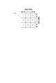
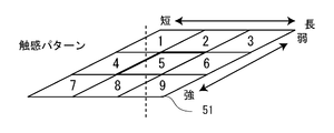
- FIG. 6 is an example of a tactile sensation pattern table 51 in which 1 to 9 indicating tactile sensation patterns are arranged.
- 1 to 9 indicating tactile sensation patterns are arranged in a matrix.
- Each of the tactile sensation patterns 1 to 9 is a combination of the parameter values of the voltage table 52, the frequency table 53, and the phase difference table 54, and the user feels the length of time (vibration length) and the tactile sensation. It represents the strength (vibration strength).
- the tactile sensation pattern table 51 shown in FIG. 6 is arranged such that the horizontal axis represents the length of the tactile sensation and the vertical axis represents the strength of the tactile sensation. Note that the arrangement of the tactile sensation pattern does not have to be a matrix. For example, as the process proceeds from 1 to 9, the length of time that the user feels vibration increases and the strength that the user feels vibration increases. It may be.
- a voltage table 52, a frequency table 53, and a phase difference table 54 are provided for the first set of piezoelectric elements.
- a voltage table 52, a frequency table 53, and a phase difference table 54 are provided for the second set of piezoelectric elements.
- a voltage table 52, a frequency table 53, and a phase difference table 54 are provided for the set of piezoelectric elements.
- the voltage table 52 is a table in which the voltage of the drive signal is changed
- the frequency table 53 is a table in which the frequency of the drive signal is changed.
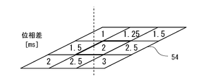
- the phase difference table 54 is a table in which the timing (delay time) of applying the drive signal is changed so that the vibration waves of the piezoelectric elements 17a to 17f have a phase difference.
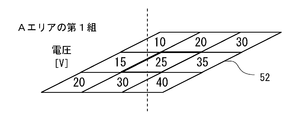
- FIG. 7 shows a voltage table 52, a frequency table 53, and a phase difference table 54 of the first set of piezoelectric elements in the A area.
- 7A shows a tactile sensation pattern table 51
- FIG. 7B shows a voltage table 52
- FIG. 7C shows a frequency table 53
- FIG. 7D shows a phase difference table 54.
- the voltage table 52, the frequency table 53, and the phase difference table 54 nine parameter values are arranged in a matrix corresponding to the tactile sensation pattern table 51, respectively.
- a voltage table 52, a frequency table 53, and a phase difference table 54 in the A area are prepared corresponding to the tactile sensation pattern table 51.
- a voltage table 52, a frequency table 53, and a phase difference table 54 are prepared corresponding to the tactile sensation pattern table 51 for each of the first to third sets of piezoelectric elements.
- FIG. 8A, FIG. 8B, and FIG. 8C are examples of parameter values of the first to third sets of piezoelectric elements in the A area, B area, and C area in the case of the tactile sensation pattern “5”.
- the vibration drive control unit 18 adds a drive signal having a voltage of 25 V and a frequency of 400 Hz to the first set of piezoelectric elements and a phase difference of 2 ms with respect to the drive signals for the third set of piezoelectric elements.
- a drive signal having a voltage of 30 V and a frequency of 400 Hz is applied to the second set of piezoelectric elements with a phase difference of 1 ms with respect to the drive signal for the third set of piezoelectric elements, and the voltage is applied to the third set of piezoelectric elements.
- a drive signal at 40 V and a frequency of 400 Hz is applied without a phase difference to the drive signals for the third set of piezoelectric elements.
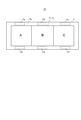
- the vibration wave generated by the first set of piezoelectric elements, the vibration wave generated by the second set of piezoelectric elements, and the vibration wave generated by the third set of piezoelectric elements are combined in area A on the touch panel 12.
- the tactile sensation of the synthetic vibration wave is stronger as the voltage applied to the piezoelectric elements 17a to 17f is higher, and is weaker as the voltage is lower.
- the touch panel device 10 may be provided with a setting unit.
- tactile sensation patterns are set in advance in the setting reference areas A to C, respectively.
- the tactile sensation patterns set in the setting reference areas A to C may be stored in the storage unit 3, for example.
- step s11 When the control unit 1 shifts to the tactile pattern setting mode by the user's operation (step s11), the control unit 1 waits until the touch panel 12 is touched (step s12), and if not touched (No in step s12), the step The process returns to s12.
- the control unit 1 controls the vibration drive control unit 18 to acquire the tactile sensation pattern set in the touched area (step s13), and corresponds to the touched area.
- the parameter values corresponding to the acquired tactile sensation patterns are acquired with reference to the voltage table 52, the frequency table 53, and the phase difference table 54 of each of the first to third sets of piezoelectric elements (step s14).
- the control unit 1 controls the vibration drive control unit 18 to vibrate the piezoelectric elements 17a to 17f for a predetermined time based on the acquired parameter value (step s15).
- the control unit 1 determines whether or not the touch is continued on the touch panel 12 (step s16).
- the control unit 1 controls the vibration drive control unit 18 to feel the touch.
- a tactile pattern next to the current tactile pattern is acquired (step s17)
- a parameter value corresponding to the acquired tactile pattern is acquired (step s14)
- the piezoelectric element 17a is obtained using the parameter value.
- ... F are vibrated for a predetermined time (step s15).
- the control unit 1 repeats the processing from step s14 to step s17 while the touch is continued (Yes in step s16).
- the tactile sensation pattern changes in the order of 1 ⁇ 2 ⁇ 3 ⁇ ... ⁇ 8 ⁇ 9 ⁇ 1 ⁇ 2 ⁇ .
- the user can check the tactile sensation pattern at the touch point in order while experiencing the touch by continuing to touch.
- the control unit 1 determines that the touch is not continued (No in step s16), and causes the display unit 11 to display a message for confirming whether to set the current tactile pattern ( Step s18).
- an operation indicating OK is performed such as touching the touch panel 12 (Yes in step s19)
- the control unit 1 sets the tactile pattern of the touched area as the current tactile pattern (step s20), and this processing Exit.
- the control unit 1 ends this process without changing the setting of the tactile sensation pattern.
- the vibration drive control unit 18 corresponds to the tactile sensation pattern set in the touched area, and the first to third sets corresponding to the touched area.
- Parameter values are acquired from the voltage table 52, the frequency table 53, and the phase difference table 54 of each piezoelectric element, and the piezoelectric elements 17a to 17f are vibrated based on the acquired parameter values.
- the touch panel device 10 includes the tactile sensation pattern table 51 that stores nine types of tactile sensation patterns in advance by combinations of the parameter values of the voltage table 52, the frequency table 53, and the phase difference table 54.
- the piezoelectric elements 17a to 17f are vibrated based on a tactile pattern selected by the user from tactile patterns in the tactile pattern table 51. Therefore, it is not necessary for the user to set each parameter value in detail, and the vibration when touching the touch panel 12 can be easily set to a desired tactile sensation. Further, by changing the tactile sensation pattern, it is possible to suppress the influence of variations in device performance, device mounting variations, ambient environment, and the like.
- each of the above parameter values is an example, and may be changed as appropriate.
- the parameter values of the phase difference table 54 may be set so that the phases of the piezoelectric elements 17a to 17f are aligned.
- the tactile sensation pattern setting may be stored for each user who has logged into the image forming apparatus 100.
Landscapes
- Engineering & Computer Science (AREA)
- General Engineering & Computer Science (AREA)
- Theoretical Computer Science (AREA)
- Human Computer Interaction (AREA)
- Physics & Mathematics (AREA)
- General Physics & Mathematics (AREA)
- Multimedia (AREA)
- Signal Processing (AREA)
- User Interface Of Digital Computer (AREA)
- Position Input By Displaying (AREA)
Abstract
Description
本発明のタッチパネル制御方法は、表示部の表示面に配置され、操作を受け付けるタッチパネルと、前記タッチパネルを振動させる複数の圧電素子とを備えたタッチパネル装置により実行されるタッチパネル制御方法であって、設定された第1パラメーターのパラメーター値と第2パラメーターのパラメーター値と第3パラメーターのパラメーター値とに基づいて、前記複数の圧電素子を駆動し、前記第1パラメーターの複数のパラメーター値を記憶した第1パラメーターテーブルと、前記第2パラメーターの複数のパラメーター値を記憶した第2パラメーターテーブルと、前記第3パラメーターの複数のパラメーター値を記憶した第3パラメーターテーブルと、前記第1パラメーターの前記複数のパラメーター値と前記第2パラメーターの前記複数のパラメーター値と前記第3パラメーターの前記複数のパラメーター値との組み合わせによる複数の触感パターン値を記憶した触感パターンテーブルと、前記触感パターンテーブルに記憶された複数の触感パターン値に基づいて、前記第1パラメーターのパラメーター値と前記第2パラメーターのパラメーター値と前記第3パラメーターのパラメーター値とを設定することを特徴とする。
本実施の形態のタッチパネル装置10が搭載された画像形成装置100は、複写機であり、図1を参照すると、原稿読取部120と、原稿給送部130と、記録部140とを備えている。原稿読取部120は、記録部140の上部に配設され、原稿給送部130は、原稿読取部120の上部に配設されている。なお、本件の画像形成装置100は、複写機で説明したが、スキャナー、複合機等が含まれるのは、言うまでもない。
方向に移動可能に構成されている。プラテンガラス122は、ガラス等の透明部材により構成された原稿台である。原稿読取スリット123は、原稿給送部130による原稿MSの搬送方向と直交方向に形成されたスリットを有する。
画像形成装置100のタッチパネル装置10、原稿読取部120、原稿給送部130、画像形成部150及び搬送部(給紙ローラー162、搬送ローラー181、排出ローラー182)は、制御部1に接続され、制御部1によって動作制御される。また、制御部1には、画像処理部2と、記憶部3とが接続されている。
Claims (7)
- 表示部の表示面に配置され、操作を受け付けるタッチパネルを有するタッチパネル装置であって、
前記タッチパネルを振動させる複数の圧電素子と、
設定された第1パラメーターのパラメーター値と第2パラメーターのパラメーター値と第3パラメーターのパラメーター値とに基づいて、前記複数の圧電素子を駆動する振動制御部と、
前記第1パラメーターの複数のパラメーター値を記憶した第1パラメーターテーブルと、
前記第2パラメーターの複数のパラメーター値を記憶した第2パラメーターテーブルと、
前記第3パラメーターの複数のパラメーター値を記憶した第3パラメーターテーブルと、
前記第1パラメーターの前記複数のパラメーター値と前記第2パラメーターの前記複数のパラメーター値と前記第3パラメーターの前記複数のパラメーター値との組み合わせによる複数の触感パターン値を記憶した触感パターンテーブルと、
前記触感パターンテーブルに記憶された複数の触感パターン値に基づいて、前記第1パラメーターのパラメーター値と前記第2パラメーターのパラメーター値と前記第3パラメーターのパラメーター値とを設定する設定部と
を備えたことを特徴とするタッチパネル装置。 - 前記触感パターンテーブルに記憶された複数の触感パターン値は、触感を感じる時間の長さと触感の強さを表す
ことを特徴とする請求項1に記載のタッチパネル装置。 - 前記第1パラメーターは、前記複数の圧電素子に印加する駆動信号の電圧であり、
前記第2パラメーターは、前記複数の圧電素子に印加する駆動信号の周波数であり、
前記第3パラメーターは、前記複数の圧電素子に印加する駆動信号の位相差である
ことを特徴とする請求項1に記載のタッチパネル装置。 - 前記複数の圧電素子は、対向するように前記タッチパネルの両辺に配置され、
前記第1パラメーターテーブルと前記第2パラメーターテーブルと前記第3パラメーターテーブルとは、前記両辺に配置された対向する1対の圧電素子毎に設けられており、
前記振動制御部は、前記1対の圧電素子毎に前記触感パターン値に基づいて駆動する ことを特徴とする請求項1に記載のタッチパネル装置。 - 前記タッチパネルには、複数の設定基準エリアが設けられ、
前記振動制御部は、
前記設定基準エリア毎に設定された前記触感パターン値で前記複数の圧電素子を駆動する
ことを特徴とする請求項1に記載のタッチパネル装置。 - 前記設定部は、
前記タッチパネルがタッチされている間、前記触感パターン値を所定時間毎に変えて、前記触感パターン値に対応する前記第1パラメーターのパラメーター値と前記第2パラメーターのパラメーター値と前記第3パラメーターのパラメーター値で前記複数の圧電素子を振動させ、前記タッチが解除された場合に、前記タッチが解除されたときの前記触感パターン値に対応する前記第1パラメーターのパラメーター値と前記第2パラメーターのパラメーター値と前記第3パラメーターのパラメーター値を前記複数の圧電素子を振動させる設定値として設定する
ことを特徴とする請求項1に記載のタッチパネル装置。 - 表示部の表示面に配置され、操作を受け付けるタッチパネルと、前記タッチパネルを振動させる複数の圧電素子とを備えたタッチパネル装置により実行されるタッチパネル制御方法であって、
設定された第1パラメーターのパラメーター値と第2パラメーターのパラメーター値と第3パラメーターのパラメーター値とに基づいて、前記複数の圧電素子を駆動し、
前記第1パラメーターの複数のパラメーター値を記憶した第1パラメーターテーブルと、
前記第2パラメーターの複数のパラメーター値を記憶した第2パラメーターテーブルと、
前記第3パラメーターの複数のパラメーター値を記憶した第3パラメーターテーブルと、
前記第1パラメーターの前記複数のパラメーター値と前記第2パラメーターの前記複数のパラメーター値と前記第3パラメーターの前記複数のパラメーター値との組み合わせによる複数の触感パターン値を記憶した触感パターンテーブルと、
前記触感パターンテーブルに記憶された複数の触感パターン値に基づいて、前記第1パラメーターのパラメーター値と前記第2パラメーターのパラメーター値と前記第3パラメーターのパラメーター値とを設定する
ことを特徴とするタッチパネル制御方法。
Priority Applications (3)
| Application Number | Priority Date | Filing Date | Title |
|---|---|---|---|
| US14/888,421 US9690422B2 (en) | 2014-01-30 | 2015-01-28 | Touch panel apparatus and touch panel control method |
| CN201580000656.6A CN105164622B (zh) | 2014-01-30 | 2015-01-28 | 触摸面板装置及触摸面板控制方法 |
| JP2015559956A JP6062573B2 (ja) | 2014-01-30 | 2015-01-28 | タッチパネル装置及びタッチパネル制御方法 |
Applications Claiming Priority (2)
| Application Number | Priority Date | Filing Date | Title |
|---|---|---|---|
| JP2014015764 | 2014-01-30 | ||
| JP2014-015764 | 2014-01-30 |
Publications (1)
| Publication Number | Publication Date |
|---|---|
| WO2015115447A1 true WO2015115447A1 (ja) | 2015-08-06 |
Family
ID=53757020
Family Applications (1)
| Application Number | Title | Priority Date | Filing Date |
|---|---|---|---|
| PCT/JP2015/052249 Ceased WO2015115447A1 (ja) | 2014-01-30 | 2015-01-28 | タッチパネル装置及びタッチパネル制御方法 |
Country Status (4)
| Country | Link |
|---|---|
| US (1) | US9690422B2 (ja) |
| JP (1) | JP6062573B2 (ja) |
| CN (1) | CN105164622B (ja) |
| WO (1) | WO2015115447A1 (ja) |
Cited By (4)
| Publication number | Priority date | Publication date | Assignee | Title |
|---|---|---|---|---|
| JP2017037523A (ja) * | 2015-08-11 | 2017-02-16 | コニカミノルタ株式会社 | 操作パネル、およびそれを備えた画像形成装置 |
| JP2017109345A (ja) * | 2015-12-15 | 2017-06-22 | コニカミノルタ株式会社 | 振動で応答する操作パネルを備えた画像処理装置 |
| JP2021157513A (ja) * | 2020-03-27 | 2021-10-07 | 日本電産コパル株式会社 | 振動アクチュエータおよびその駆動方法 |
| JP2022172796A (ja) * | 2021-05-07 | 2022-11-17 | コニカミノルタ株式会社 | 操作入力装置および画像形成装置 |
Families Citing this family (5)
| Publication number | Priority date | Publication date | Assignee | Title |
|---|---|---|---|---|
| JP6062573B2 (ja) * | 2014-01-30 | 2017-01-18 | 京セラドキュメントソリューションズ株式会社 | タッチパネル装置及びタッチパネル制御方法 |
| CN111538408A (zh) * | 2020-04-07 | 2020-08-14 | 瑞声科技(新加坡)有限公司 | 基于振动的指示方法、触控组件、终端和可读存储介质 |
| WO2023159362A1 (zh) * | 2022-02-22 | 2023-08-31 | 京东方科技集团股份有限公司 | 触觉反馈面板、其驱动方法及触觉反馈装置 |
| CN114708898B (zh) * | 2022-04-07 | 2025-06-10 | 合肥兆芯电子有限公司 | 表格管理方法、存储器存储装置及存储器控制电路单元 |
| JP2025073844A (ja) * | 2023-10-27 | 2025-05-13 | 太陽誘電株式会社 | 操作装置、ステアリングホイール、電子機器及び操作パネルの制御方法 |
Citations (4)
| Publication number | Priority date | Publication date | Assignee | Title |
|---|---|---|---|---|
| JP2006163579A (ja) * | 2004-12-03 | 2006-06-22 | Sony Corp | 情報処理システム、情報処理装置及び情報処理方法 |
| JP2012520520A (ja) * | 2009-03-12 | 2012-09-06 | イマージョン コーポレイション | テクスチャを実現するために複数のアクチュエータを用いるシステム及び方法 |
| JP2013511108A (ja) * | 2009-11-17 | 2013-03-28 | イマージョン コーポレイション | 電子デバイスにおける触覚帯域を増加するためのシステム及び方法 |
| WO2013186847A1 (ja) * | 2012-06-11 | 2013-12-19 | 富士通株式会社 | 駆動装置、電子機器、及び駆動制御プログラム |
Family Cites Families (25)
| Publication number | Priority date | Publication date | Assignee | Title |
|---|---|---|---|---|
| US4103252A (en) * | 1976-11-26 | 1978-07-25 | Xerox Corporation | Capacitive touch-activated transducer system including a plurality of oscillators |
| US5880411A (en) * | 1992-06-08 | 1999-03-09 | Synaptics, Incorporated | Object position detector with edge motion feature and gesture recognition |
| JP4230318B2 (ja) | 2003-09-11 | 2009-02-25 | 株式会社イシダ | 商品情報処理装置 |
| JP4518780B2 (ja) | 2003-11-19 | 2010-08-04 | 株式会社リコー | 機器操作装置、機器操作方法、プログラム及びコンピュータ読み取り可能な記録媒体 |
| JP2007011785A (ja) | 2005-06-30 | 2007-01-18 | Toshiba Corp | 情報処理装置、およびタッチパネルの振動制御方法 |
| US20090091479A1 (en) * | 2007-10-04 | 2009-04-09 | Motorola, Inc. | Keypad haptic communication |
| EP2202623A1 (en) | 2008-12-23 | 2010-06-30 | Research In Motion Limited | Portable electronic device and method of control |
| EP2202619A1 (en) | 2008-12-23 | 2010-06-30 | Research In Motion Limited | Portable electronic device including tactile touch-sensitive input device and method of controlling same |
| US9746923B2 (en) | 2009-03-12 | 2017-08-29 | Immersion Corporation | Systems and methods for providing features in a friction display wherein a haptic effect is configured to vary the coefficient of friction |
| WO2011024434A1 (ja) * | 2009-08-27 | 2011-03-03 | 京セラ株式会社 | 触感呈示装置及び触感呈示装置の制御方法 |
| US8698766B2 (en) | 2010-04-22 | 2014-04-15 | Maxim Integrated Products, Inc. | System integration of tactile feedback and touchscreen controller for near-zero latency haptics playout |
| JP5912235B2 (ja) * | 2010-07-27 | 2016-04-27 | 京セラ株式会社 | 触感呈示装置及び触感呈示装置の制御方法 |
| JP5841714B2 (ja) * | 2010-07-27 | 2016-01-13 | 京セラ株式会社 | 触感呈示装置及び触感呈示装置の制御方法 |
| JP2012027855A (ja) * | 2010-07-27 | 2012-02-09 | Kyocera Corp | 触感呈示装置及び触感呈示装置の制御方法 |
| JP5841713B2 (ja) * | 2010-07-27 | 2016-01-13 | 京セラ株式会社 | 触感呈示装置及び触感呈示装置の制御方法 |
| US8677238B2 (en) * | 2010-10-21 | 2014-03-18 | Sony Computer Entertainment Inc. | Navigation of electronic device menu without requiring visual contact |
| DE102011017250B4 (de) * | 2011-01-07 | 2022-12-01 | Maxim Integrated Products, Inc. | Berührungs-Feedbacksystem, haptisches Feedbacksystem und Verfahren zum Bereitstellen eines haptischen Feedbacks |
| KR101328054B1 (ko) * | 2011-08-09 | 2013-11-08 | 엘지전자 주식회사 | 실감 진동을 발생시키는 영상표시장치 및 실감 진동 구현방법 |
| US9335822B2 (en) * | 2012-12-12 | 2016-05-10 | Immersion Corporation | Method and system for providing haptic effects based on haptic context information |
| US9939900B2 (en) * | 2013-04-26 | 2018-04-10 | Immersion Corporation | System and method for a haptically-enabled deformable surface |
| CN105556423B (zh) * | 2013-06-11 | 2019-01-15 | 意美森公司 | 用于基于压力的触觉效果的系统和方法 |
| JP6086350B2 (ja) * | 2013-08-09 | 2017-03-01 | 株式会社デンソー | タッチパネル式入力装置、およびタッチパネル式入力方法 |
| US9652097B2 (en) * | 2013-11-29 | 2017-05-16 | Hideep Inc. | Feedback method according to touch level and touch input device performing the same |
| JP6062573B2 (ja) * | 2014-01-30 | 2017-01-18 | 京セラドキュメントソリューションズ株式会社 | タッチパネル装置及びタッチパネル制御方法 |
| US20150241970A1 (en) * | 2014-02-27 | 2015-08-27 | Samsung Electronics Co., Ltd. | Method and apparatus for providing haptic effect |
-
2015
- 2015-01-28 JP JP2015559956A patent/JP6062573B2/ja not_active Expired - Fee Related
- 2015-01-28 CN CN201580000656.6A patent/CN105164622B/zh not_active Expired - Fee Related
- 2015-01-28 US US14/888,421 patent/US9690422B2/en not_active Expired - Fee Related
- 2015-01-28 WO PCT/JP2015/052249 patent/WO2015115447A1/ja not_active Ceased
Patent Citations (4)
| Publication number | Priority date | Publication date | Assignee | Title |
|---|---|---|---|---|
| JP2006163579A (ja) * | 2004-12-03 | 2006-06-22 | Sony Corp | 情報処理システム、情報処理装置及び情報処理方法 |
| JP2012520520A (ja) * | 2009-03-12 | 2012-09-06 | イマージョン コーポレイション | テクスチャを実現するために複数のアクチュエータを用いるシステム及び方法 |
| JP2013511108A (ja) * | 2009-11-17 | 2013-03-28 | イマージョン コーポレイション | 電子デバイスにおける触覚帯域を増加するためのシステム及び方法 |
| WO2013186847A1 (ja) * | 2012-06-11 | 2013-12-19 | 富士通株式会社 | 駆動装置、電子機器、及び駆動制御プログラム |
Cited By (7)
| Publication number | Priority date | Publication date | Assignee | Title |
|---|---|---|---|---|
| JP2017037523A (ja) * | 2015-08-11 | 2017-02-16 | コニカミノルタ株式会社 | 操作パネル、およびそれを備えた画像形成装置 |
| JP2017109345A (ja) * | 2015-12-15 | 2017-06-22 | コニカミノルタ株式会社 | 振動で応答する操作パネルを備えた画像処理装置 |
| US10069987B2 (en) | 2015-12-15 | 2018-09-04 | Konica Minolta, Inc. | Image processing device with operation panel responding by vibration |
| JP2021157513A (ja) * | 2020-03-27 | 2021-10-07 | 日本電産コパル株式会社 | 振動アクチュエータおよびその駆動方法 |
| JP7373445B2 (ja) | 2020-03-27 | 2023-11-02 | ニデックプレシジョン株式会社 | 振動アクチュエータおよびその駆動方法 |
| JP2022172796A (ja) * | 2021-05-07 | 2022-11-17 | コニカミノルタ株式会社 | 操作入力装置および画像形成装置 |
| JP7835536B2 (ja) | 2021-05-07 | 2026-03-25 | コニカミノルタ株式会社 | 操作入力装置および画像形成装置 |
Also Published As
| Publication number | Publication date |
|---|---|
| CN105164622A (zh) | 2015-12-16 |
| CN105164622B (zh) | 2018-06-15 |
| US9690422B2 (en) | 2017-06-27 |
| JP6062573B2 (ja) | 2017-01-18 |
| JPWO2015115447A1 (ja) | 2017-03-23 |
| US20160110014A1 (en) | 2016-04-21 |
Similar Documents
| Publication | Publication Date | Title |
|---|---|---|
| JP6062573B2 (ja) | タッチパネル装置及びタッチパネル制御方法 | |
| JP5410555B2 (ja) | タッチパネル装置 | |
| US9342150B2 (en) | Display input device, image forming apparatus including the display input device, and method of controlling the display input device | |
| CN103685807B (zh) | 显示输入装置和图像形成装置 | |
| JP5781495B2 (ja) | タッチパネル装置 | |
| JP2014131133A (ja) | 操作入力装置、情報処理装置 | |
| JP2015162152A (ja) | タッチパネル装置及び画像形成装置 | |
| JP2015162153A (ja) | タッチパネル装置及び画像形成装置 | |
| JP5868903B2 (ja) | タッチパネル装置、画像形成装置 | |
| JP5976212B2 (ja) | 表示入力装置、情報処理装置、タッチパネル装置 | |
| JP5802234B2 (ja) | 入力装置、入力方法及び電子機器 | |
| US20170171406A1 (en) | Image processing device with operation panel responding by vibration | |
| JP5996515B2 (ja) | 操作パネル装置及び画像形成装置 | |
| JP2015106231A (ja) | 操作パネル装置及び画像形成装置 | |
| JP2015031982A (ja) | タッチパネル装置及び画像形成装置 | |
| JP2015104835A (ja) | 操作パネル装置及び画像形成装置 | |
| JP2015011516A (ja) | 操作表示装置及び画像形成装置 | |
| JP2016033727A (ja) | タッチパネル装置及びタッチパネル装置を備える画像形成装置 |
Legal Events
| Date | Code | Title | Description |
|---|---|---|---|
| WWE | Wipo information: entry into national phase |
Ref document number: 201580000656.6 Country of ref document: CN |
|
| 121 | Ep: the epo has been informed by wipo that ep was designated in this application |
Ref document number: 15742602 Country of ref document: EP Kind code of ref document: A1 |
|
| ENP | Entry into the national phase |
Ref document number: 2015559956 Country of ref document: JP Kind code of ref document: A |
|
| WWE | Wipo information: entry into national phase |
Ref document number: 14888421 Country of ref document: US |
|
| NENP | Non-entry into the national phase |
Ref country code: DE |
|
| 122 | Ep: pct application non-entry in european phase |
Ref document number: 15742602 Country of ref document: EP Kind code of ref document: A1 |